JP2016007751A - Film deposition device and film deposition method - Google Patents
Film deposition device and film deposition method Download PDFInfo
- Publication number
- JP2016007751A JP2016007751A JP2014129239A JP2014129239A JP2016007751A JP 2016007751 A JP2016007751 A JP 2016007751A JP 2014129239 A JP2014129239 A JP 2014129239A JP 2014129239 A JP2014129239 A JP 2014129239A JP 2016007751 A JP2016007751 A JP 2016007751A
- Authority
- JP
- Japan
- Prior art keywords
- film
- welding
- welded
- welding head
- container
- Prior art date
- Legal status (The legal status is an assumption and is not a legal conclusion. Google has not performed a legal analysis and makes no representation as to the accuracy of the status listed.)
- Pending
Links
Images
Landscapes
- Lining Or Joining Of Plastics Or The Like (AREA)
Abstract
【課題】フィルムを被溶着物に適確に溶着することができるフィルム溶着装置およびフィルム溶着方法を提供すること。【解決手段】容器11のフランジ部13に熱溶着されるフィルム12の表面に熱溶着ヘッド24が当接する前に、フランジ部13の表面に沿って回転ローラ26を矢印31方向に移動させて、フィルム12の表面の位置を規制する。【選択図】図3A film welding apparatus and a film welding method capable of accurately welding a film to an object to be welded are provided. Before a thermal welding head 24 comes into contact with the surface of a film 12 to be thermally welded to a flange portion 13 of a container 11, a rotating roller 26 is moved in the direction of an arrow 31 along the surface of the flange portion 13; The position of the surface of the film 12 is regulated. [Selection] Figure 3
Description
本発明は、フィルムを被溶着物に溶着するためのフィルム溶着装置およびフィルム溶着方法に関するものである。 The present invention relates to a film welding apparatus and a film welding method for welding a film to an object to be welded.
フィルムを被溶着物に溶着する方法としては、帯状のフィルムを被溶着物に熱溶着等によって溶着した後に、そのフィルムを所定寸法に切断する方法と、予め所定寸法に切断したフィルムを被溶着物に熱溶着等によって溶着する方法がある。前者の方法としては、例えば、特許文献1に、内容物が充填された容器の開口部に、連続的に繰り出される帯状のフィルムを熱溶着し、その後、フィルムを所定寸法に切断する方法が記載されている。
As a method of welding the film to the object to be welded, after the belt-like film is welded to the object to be welded by heat welding or the like, the film is cut into a predetermined dimension, and the film cut into a predetermined dimension in advance is welded. There is a method of welding by heat welding or the like. As the former method, for example,
しかしながら、特許文献1に記載の方法によって、フィルムの熱溶着と切断を連続的に行った場合には、フィルムの熱溶着後からフィルムの切断までの時間が短くなりやすい。そのため、容器とフィルムの熱溶着部が充分に冷却される前にフィルムが切断されるおそれがあり、その場合には、フィルムの切断時にフィルムを剥がす方向の力が作用して、容器内の内容物のリークあるいはフィルムの剥がれが生じるおそれがある。また、容器のロットの違いにより溶着状態に差が生じて、切断後のフィルム寸法に差が生じるおそれもある。
However, when the thermal welding and cutting of the film are continuously performed by the method described in
一方、フィルムを所定寸法に切断した後に熱溶着する方法においては、このようなおそれは生じない。しかし、容器の開封時に把持されるフィルムの狭い領域のみが容器の開口部からはみ出る場合には、熱溶着時にフィルムを保持する箇所は、その狭い領域のみに制限される。熱溶着時に、そのような狭い領域のフィルムのみを保持した場合には、フィルムの他の領域の部分がカールするおそれがある。さらに、フィルムが複合層構造の場合には、初期のカール、溶着時の熱による反り、および自重によるカールの影響を受けやすい。これらのフィルムのカールの影響により、容器とフィルムの熱溶着部に対するフィルムの角部の挟み込み、およびフィルムのカール部が周辺部に接触することによる溶着位置のずれなどが生じるおそれがある。 On the other hand, such a fear does not occur in the method of thermally welding after cutting the film to a predetermined size. However, in the case where only a narrow region of the film held when the container is opened protrudes from the opening of the container, the place where the film is held at the time of heat welding is limited to only the narrow region. If only such a narrow area film is held at the time of heat welding, there is a possibility that the other area portion of the film curls. Further, when the film has a composite layer structure, it is easily affected by initial curling, warping due to heat during welding, and curling due to its own weight. Under the influence of the curl of these films, there is a possibility that the corners of the film are sandwiched between the heat-welded portions of the container and the film, and the welding position is displaced due to the curled portions of the film coming into contact with the peripheral portions.
本発明の目的は、フィルムを被溶着物に適確に溶着することができるフィルム溶着装置およびフィルム溶着方法を提供することにある。 An object of the present invention is to provide a film welding apparatus and a film welding method capable of accurately welding a film to an object to be welded.
本発明のフィルム溶着装置は、被溶着物の被溶着面上に位置するフィルムの表面に溶着ヘッドを当接させることによって、前記フィルムを前記被溶着面に溶着させるフィルム溶着装置であって、前記被溶着面上における前記フィルムの前記表面の位置を規制するように、前記被溶着面に沿って移動可能な規制体と、前記溶着ヘッドが前記フィルムの前記表面に当接する前に、前記規制体を前記被溶着面に沿って移動させる移動手段と、を備える。 The film welding apparatus of the present invention is a film welding apparatus for welding the film to the welding surface by bringing a welding head into contact with the surface of the film located on the welding surface of the object to be welded, A regulating body movable along the welding surface so as to regulate the position of the surface of the film on the welding surface, and the regulating body before the welding head contacts the surface of the film. Moving means for moving along the welding surface.
本発明によれば、被溶着物の被溶着面に溶着されるフィルムの表面に溶着ヘッドが当接する前に、被溶着面に沿って規制体を移動させることにより、被溶着面上におけるフィルムの表面の位置を規制することができる。この結果、フィルムが非溶着面に対応する形状に予め切断されている場合であっても、そのフィルムのカールを規制体によって矯正してから、そのフィルムを被溶着物に適確に溶着することができる。つまり、予め所定寸法に切断されたフィルムに生じやすいカールの影響を受けることなく、そのフィルムを適確に溶着することができる。より具体的には、フィルムの角部分の溶着部分への挟み込み、およびフィルムの溶着位置のずれなどの溶着不良の発生を抑制することができる。 According to the present invention, before the welding head comes into contact with the surface of the film to be welded to the welding surface of the object to be welded, the regulating body is moved along the surface to be welded. The position of the surface can be regulated. As a result, even if the film is cut in advance to a shape corresponding to the non-welded surface, the curl of the film is corrected by the regulating body, and then the film is welded accurately to the object to be welded. Can do. That is, the film can be accurately welded without being affected by the curl that is likely to occur in the film that has been cut to a predetermined size in advance. More specifically, it is possible to suppress the occurrence of poor welding such as sandwiching of the corner portion of the film into the welded portion and displacement of the welding position of the film.
以下、本発明の実施形態について図面を参照して説明する。 Embodiments of the present invention will be described below with reference to the drawings.
(第1の実施形態)
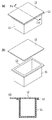
図1は、所定寸法に切断されたフィルム12、およびフィルム12が溶着される被溶着物としての容器11の説明図である。図1(a)は、フィルム12が溶着された容器11の斜視図、図1(b)は、フィルム12と容器11の分解斜視図、図1(c)は、図1(a)のIc−Ic線に沿う断面図である。
(First embodiment)
FIG. 1 is an explanatory view of a
本例において、容器11の材質はポリプロピレン(以下、「PP」ともいう)であり、そのPPの厚みは1[mm]とした。フィルム12は、溶着層/ガスバリア層/外層等からなる多層のフィルムであり、容器11とフィルム12の両方が互いに溶け合って熱溶着されるように、溶着層は容器11と同様のPPとし、フィルム12のトータルの厚みは0.12[mm]とした。このような容器11とフィルム12の材質、およびフィルム12の層構造は単なる一例であり、容器11内に収容される内容物の保護、外観、容器11とフィルム12の溶着強度などに応じて、種々選定することができる。例えば、容器11の本体を紙とし、フィルム12が溶着される容器11のフランジ部13のみにPPのコート層を形成してもよい。
In this example, the material of the
(溶着装置の構成)
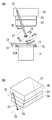
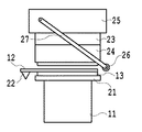
図2は、容器11にフィルム12を熱溶着するためのフィルム溶着装置の要部の概略構成図である。
(Configuration of welding equipment)
FIG. 2 is a schematic configuration diagram of a main part of a film welding apparatus for thermally welding the
本例の溶着装置は、容器11を固定するための容器固定治具21を備えており、その容器固定治具21の孔21Aに容器11を嵌め込み、孔21Aの上側開口部によって容器11のフランジ部13の位置を規制する。フランジ部13は、フィルム12が熱溶着される被溶着面を形成する。溶着装置は、被溶着面に対応するように所定寸法に切断されたフィルム12を保持して搬送するために、その一部分を吸着保持する吸着パッド22を備えている。本例の場合、吸着パッド22が吸着保持するフィルム12の部分は、熱溶着後に、フランジ部13から外方に延出する延出部であって、かつ容器11の開封時に使用者によって把持される狭い領域の部分である。また溶着装置は、容器11にフィルム12を熱溶着するために、断熱部材23を介して熱溶着ヘッド24を保持する溶着ヘッド本体25を備えている。
The welding apparatus of this example includes a
溶着ヘッド本体25において互いに反対側に位置する部分には、2つの支持体27の上端部が水平方向の軸線O1を中心として矢印A1,A2方向に回動自在に軸支されている。それらの支持体27の下端部の相互間には、熱溶着ヘッド24の下方に位置する回転ローラ(規制体)26が軸線O1と同方向の軸線O2を中心として回転自在に軸支されている。フィルム12が吸着パッド22によって容器11のフランジ部13上に搬送されてから、溶着ヘッド本体25の下降したときには、熱溶着ヘッド24よりも先に、回転ローラ26がフィルム12に当接して移動する。これにより、後述するように、回転ローラ26によってフィルム12の表面の位置が規制されて、フィルム12のカール部が矯正されてから、そのフィルム12が熱溶着ヘッド24によってフランジ部13に熱溶着される。フィルム12を保持して搬送するための構成は、吸着パッド22を用いる構成のみに限定されず、フィルム12を所定位置に搬送することができる構成であればよい。例えば、フィルム12の端部をチャックにより把持して搬送する構成であってもよい。
The upper end portions of the two
後述するように、フランジ部13上にフィルム12が位置する容器11と、熱溶着ヘッド24と、を不図示の移動機構によって相対的に近接移動させたときに、フランジ部13上において、回転ローラ26と共に支持体27の下端部が矢印31方向に水平移動する。支持体27の支点(軸線O1)は、矢印31方向に沿う熱溶着ヘッド24の幅方向における中央部(図2中の左右方向の中央部)から、吸着パッド22側にずれた位置に設定されている。支持体27の矢印A2方向の回動位置は、鉛直方向から矢印31方向に所定の傾き32をもつ位置に制限されており、支持体27の下端部の矢印31方向の移動に伴って、支持体27の傾きが大きくなる。
As will be described later, when the
(溶着装置の基本動作)
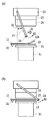
図3は、溶着装置の基本動作を説明するための図であり、図3(a)は、熱溶着前の待機状態における溶着装置の動作の説明図、図3(b)は、熱溶着時における溶着装置の動作の説明図である。熱溶着時には、フランジ部13上にフィルム12が位置する容器11と、熱溶着ヘッド24と、を不図示の移動機構によって相対的に近接移動させる。これにより、回転ローラ26が容器11上のフィルム12に接して、回転ローラ26が支持体27の下端部と共に矢印A1方向に回動する。この結果、回転ローラ26が支持体27の下端部と共に、フランジ部13に沿って矢印31方向に水平移動し、回転ローラ26がフィルム12のカール部12Aを矯正する。図3(b)のように、熱溶着ヘッド24が容器11上のフィルム12に接して、フィルム12を容器11のフランジ部13に熱溶着するときには、回転ローラ26がフィルム12から外れた位置に移動する。回転ローラ26が図3(b)のような位置に移動することにより、回転ローラ26によるフィルム12のカール矯正が解除される。
(Basic operation of welding equipment)
3A and 3B are diagrams for explaining the basic operation of the welding apparatus. FIG. 3A is an explanatory diagram of the operation of the welding apparatus in a standby state before thermal welding, and FIG. It is explanatory drawing of operation | movement of the welding apparatus in. At the time of heat welding, the
回転ローラ26の移動方向は、矢印31のように、吸着パッド22がフィルム12を保持する図3(a)中の左側から、それとは反対の同図中の右側に向かう方向が望ましい。その理由は、回転ローラ26によるカール矯正の解除の直前まで、つまりフィルム12の熱溶着の直前まで、フィルム12のカール部12Aを効率よく矯正することができるからである。つまり、吸着パッド22がフィルム12を保持する位置を固定側として、フィルム12を図3(b)中の右側に引き伸ばすようにして、回転ローラ26がフィルム12のカール部12Aを効率よく矯正することができる。したがって、カール部12Aが矯正されたフィルム12を容器11のフランジ部13に適確に溶着することができる。
The moving direction of the
本実施形態においては、容器11と熱溶着ヘッド24との相対的な近接移動により、支持体27の矢印A1方向の回動を伴って、回転ローラ26がフィルム12を介してフランジ部13に接しつつ転動して、フランジ部13に沿って水平の矢印31方向に移動する。このように、本例における回転ローラ26の移動機構は、容器11と熱溶着ヘッド24との相対的な近接移動に基づいて、支持体27の回動を伴って回転ローラ26を自動的に移動させる構成となっている。このような移動機構においては、フィルム12との間の摩擦を低減するために回転ローラ26を備えることが望ましい。その回転ローラ26は、本例のような長尺な円柱状のローラのみに限定されず、例えば、フランジ部13のみと対向する短いローラであってもよい。また、フィルム12に対する支持体27の下端部の滑り性が良ければ、回転ローラ26を備えずに、支持体27の下端部を直接、フランジ部13上のフィルム12に接触させて矢印31方向に移動させるようにしてもよい。
In the present embodiment, the
回転ローラ26を移動させる移動機構は本例の構成のみに限定されず任意であり、例えば、容器11と熱溶着ヘッド24との相対的な近接移動に同期して、種々のアクチュエータによって回転ローラ26を移動させる構成であってもよい。要は、容器11と熱溶着ヘッド24との相対的な近接移動および離間移動に応じて、回転ローラ26を容器11のフランジ部13に沿って移動できる構成であればよい。支持体27の支点(軸線O1)の位置、および待機状態における回転ローラ26の位置は、待機状態における熱溶着ヘッド24とフィルム12との間のクリアランス、および回転ローラ26とフィルム12の表面の滑り性などに基づいて適宜設定する。
The moving mechanism for moving the rotating
(溶着動作)
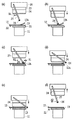
図4(a)から図4(e)は、一連の溶着動作をより具体的に説明するための図である。
(Welding operation)
FIG. 4A to FIG. 4E are diagrams for more specifically explaining a series of welding operations.
まず、図4(a)のように、内容物を収容した容器11のフランジ部13上に、所定寸法に切断されたフィルム12を吸着パッド22によって搬送する。このとき、容器11は容器固定治具21に保持されている。次に、図4(b)のように、容器11と熱溶着ヘッド24とを相対的に近接移動させて、回転ローラ26をフィルム12に接触させる。本例の場合は、容器11に対して熱溶着ヘッド24を下降させる。さらに、熱溶着ヘッド24を下降させることにより、図4(c)のように、支持体27の矢印A1方向の回動と回転ローラ26の回転を伴って、支持体27の下端部が回転ローラ26と共に矢印31方向に移動する。このように、回転ローラ26をフィルム12に押し付けつつ移動させることにより、フィルム12におけるカール部12Aが徐々に矯正される。このとき、フィルム12の位置がずれないように、吸着パッド22が充分な吸着力によってフィルム12を保持している。
First, as shown in FIG. 4A, the
さらに熱溶着ヘッド24が下降することにより、図4(d)のように、回転ローラ26がフィルム12上から離れて、カール矯正の解除状態となる。その直後、つまり回転ローラ26がフィルム12上から離れた直後においては、熱溶着ヘッド24と容器11の上面との間の距離が回転ローラ26の直径よりも大きく、かつ熱溶着ヘッド24がカール部12Aの変形を抑制する状態となる。好ましくは、熱溶着ヘッド24は、フィルム12の表面から回転ローラ26の直径の1.5倍以上、上方に離れて位置する。その後、さらに熱溶着ヘッド24が下降することにより、図4(e)のように、熱溶着ヘッド24がフィルム12に当接し、所定荷重を掛けてフィルム12を容器11のフランジ部13に熱溶着する。その後、図4(f)のように、不図示の移動機構によって熱溶着ヘッド24を上昇させると共に、容器固定治具21によるフィルム12の吸着保持を解除して溶着を終了する。これにより、フィルム12を溶着した容器11が製品として完成する。支持体27は、その自重により矢印A2方向に回動復帰する。
When the
このような熱溶着方法により、フィルム12のカール部12Aの影響を小さく抑えて、熱溶着部に対するフィルム12の角部の挟み込み、およびフィルム12の溶着位置のずれなどの溶着不良の発生を抑制して、信頼性の高い熱溶着を実現することができる。また、予め、フィルム12が所定の寸法に切断されているため、溶着後にフィルム12を切断する必要ながない。
By such a heat welding method, the influence of the curled
(第2の実施形態)
本実施形態では、予め回転ローラ26を加熱させておいてから、溶着動作を実行する。回転ローラ26の加熱温度は、容器11とフィルム12の溶着層に使用しているPPの融点(170[℃]程度)とした。回転ローラ26を加熱する以外は、前述した実施形態と同様である。
(Second Embodiment)
In the present embodiment, the welding operation is performed after the
前述した実施形態と同様に、まずは、図4(a)のように、所定寸法に切断されたフィルム12を内容物が充填された容器11のフランジ部13上に搬送する。このとき、容器11は容器固定治具21に保持されている。次に、図4(b)のように、熱溶着ヘッド24が下降することにより回転ローラ26がフィルム12に当接してから、図4(c)のように、支持体27の先端部と共に回転ローラ26が矢印31方向に移動して、フィルム12のカール部12Aを矯正する。このとき、吸着パッド22は、フィルム12の位置がずれないように、充分な吸着力によってフィルム12を保持している。次に、図5のように、回転ローラ26がフィルム12上から離れてカール矯正の解除状態となる。
As in the above-described embodiment, first, as shown in FIG. 4A, the
本実施形態においては、回転ローラ26が加熱されているため、フィルム12上における回転ローラ26の矢印31方向の移動に伴って、フィルム12が容器11のフランジ部13に徐々に仮溶着される。したがって、図5のようなカール矯正の解除状態となったときは、フィルム12は、カール部12Aが矯正された状態のまま、容器11のフランジ部13に仮溶着されることになる。
In this embodiment, since the rotating
その後、図4(e)のように、熱溶着ヘッド24がフィルム12に当接し、所定荷重を掛けてフィルム12と容器11のフランジ部13とを熱溶着(本溶着)する。その後、図4(f)のように、熱溶着ヘッド24を上昇させると共に、容器固定治具21によるフィルム12の吸着保持を解除して溶着を終了する。
Thereafter, as shown in FIG. 4E, the
このような溶着方法により、フィルム12のカール矯正時に、そのフィルム12を容器11に仮溶着することができる。したがって、熱溶着ヘッド24による溶着の直前に、カール部12Aの影響によってフィルム12の端部が熱溶着ヘッド24に当接することを防止し、その当接により生じるフィルム12の熱変形、および、それに起因する溶着不良の発生を防止することができる。また、フィルム12と容器11の熱溶着部に充分な強度を確保しつつ、過溶着を防ぐためには、荷重制御によって所定荷重を掛けながら熱溶着を行う必要がある。本例においては、回転ローラ26による荷重制御が難しいことから、回転ローラ26による仮溶着と、熱溶着ヘッド24による本溶着と、を組み合わせた。回転ローラ26による荷重制御が可能な場合には、回転ローラ26だけで本溶着をすることもできる。
With such a welding method, the
また、本実施形態においては、加熱した回転ローラ26によってフィルム12を容器11に仮溶着した。フィルム12のフィルム層構造によっては、それらの層の熱収縮の差によってカールを抑制することができるため、回転ローラ26の加熱温度を下げて、回転ローラ26によっては仮溶着せずに、その熱によってフィルム12のカール部12Aを矯正してもよい。
In the present embodiment, the
(他の実施形態)
上述した実施形態においては、フィルム12を介して、回転ローラ26を容器11の被溶着面に接触させつつ、その被溶着面に沿って移動させることにより、フィルム12の表面の位置を規制して、カール部12Aを矯正した。しかし、このようにフィルム12の表面の位置を規制する規制体は、回転ローラ26のみに限定されず、フィルム12との間の摩擦抵抗が小さくてフィルム12と摺接する部材であってもよい。例えば、支持体27の一部によって規制体を構成してもよい。また規制体は、フィルムの溶着前に、溶着後のフィルムの表面の若干上方の位置を被溶着面に沿って移動可能であってもよく、要は、溶着前のフィルム12の表面の位置を規制することができればよい。
(Other embodiments)
In the above-described embodiment, the position of the surface of the
また、このような規制体を移動させるための移動機構は、前述した実施形態のように支持体27を用いる構成のみに特定されない。例えば、容器11と熱溶着ヘッド24との相対的な近接および離間移動に同期して、種々のアクチュエータによって規制体を移動させる構成であってもよい。要は、熱溶着ヘッド24が被溶着面上のフィルム12の表面に当接する前に、被溶着面に沿って規制体を移動させることができればよい。また、移動体の代わりに、空気や不活性ガスなどの気体を被溶着面上のフィルム12の表面に吹き掛けて、そのフィルム12を被溶着面に沿わせるように、フィルム12の表面の位置を規制してもよい。その場合、フィルム12の表面の位置を規制するときの規制体の移動方向に沿うように、気体を吹き掛ける方向を設定することが望ましい。気体の吹き付け速度および吹き付け量の吹き付け条件は、フィルム12の剛性などに応じて最適に調整することができる。
Moreover, the moving mechanism for moving such a regulating body is not specified only in the structure using the
また、容器11と熱溶着ヘッド24の相対移動の方向は、上下方向のみに特定されず、被溶着面上にフィルム12を位置決め可能であればよい。また、必要に応じて、熱溶着後のフィルム12の少なくとも一部を切断してもよい。本発明において採用する溶着方式は、熱溶着のみに限定されず、超音波溶着および高周波溶着などの種々の方式を採用することができる。いずれの方式においても、溶着ヘッドがフィルムを溶着する前に、被溶着面に沿って規制体を移動させることができればよい。
Further, the direction of relative movement between the
以下、本発明の実施例1として、前述した第1の実施形態に適用可能な溶着装置の具体的な構成例、および具体的な溶着方法について説明する。なお、本発明は以下の実施例に限定されない。 Hereinafter, as Example 1 of the present invention, a specific configuration example and a specific welding method of the welding apparatus applicable to the above-described first embodiment will be described. The present invention is not limited to the following examples.
本実施例において使用した容器11のサイズは、縦40[mm]×横70[mm]×高さ40[mm]であり、図1のように、容器11の開口部の全周に渡って、幅5[mm]のフランジ部13が形成されている。また、フランジ部13の中央には、全周に渡って幅1.2[mm]×高さ0.2[mm]の溶着リブ(図示せず)が形成されている。フィルム12のサイズは、縦65[mm]×横80[mm]であり、図1のように、フィルム12の一辺のみがフランジ部13からはみ出る形状となっている。
The size of the
熱溶着ヘッド24の先端面(フィルム12と当接する面)の形状は、容器11の溶着リブの形状に対応し、容器11とフィルム12の溶着部に対応する溶着面の幅は3[mm]である。支持体27は、図2のように、鉛直方向に対して矢印31方向に所定の傾き32をもつように溶着ヘッド本体25に軸支される。支持体27の支点(軸線O1)の位置は、容器固定治具21によって保持されるフィルム12の保持部側(図2中の左側)におけるフランジ部13の鉛直方向の上方とした。支持体27の下端部には、直径4[mm]の円柱状の回転ローラ26が回転自在に取り付けられ、その回転ローラ26は、フィルム12上における移動に伴って回転する。図3(a)のような待機状態における回転ローラ26の位置は、同図のように、容器固定治具21に固定された容器11のほぼ中央の位置とした。回転ローラ26は、熱溶着ヘッド24の下降に伴って、フィルム12に接触しつつ矢印31方向に水平移動し、熱溶着ヘッド24がフィルム12に当接する際には、回転ローラ26はフィルム12上から離脱して、図3(b)のようなカール矯正の解除状態となる。
The shape of the front end surface of the thermal welding head 24 (the surface in contact with the film 12) corresponds to the shape of the welding rib of the
11 容器(被溶着物)
12 フィルム
13 フランジ部
22 吸着パッド(保持部)
24 熱溶着ヘッド(溶着ヘッド)
26 回転ローラ(規制体)
27 支持体
11 Container (to be welded)
12
24 Thermal welding head (welding head)
26 Rotating roller (regulator)
27 Support
Claims (12)
前記被溶着面上における前記フィルムの前記表面の位置を規制するように、前記被溶着面に沿って移動可能な規制体と、
前記溶着ヘッドが前記フィルムの前記表面に当接する前に、前記規制体を前記被溶着面に沿って移動させる移動手段と、
を備えることを特徴とするフィルム溶着装置。 A film welding apparatus for welding the film to the surface to be welded by bringing a welding head into contact with the surface of the film located on the surface to be welded.
A regulating body movable along the welding surface so as to regulate the position of the surface of the film on the welding surface;
Moving means for moving the regulating body along the welding surface before the welding head abuts on the surface of the film;
A film welding apparatus comprising:
前記移動手段は、前記フィルムの前記一部分から前記フィルムの他の部分に向かう方向に、前記規制体を移動させる請求項1に記載のフィルム溶着装置。 Holding means for holding a part of the film so as to position the film on the welding surface;
The film welding apparatus according to claim 1, wherein the moving unit moves the regulating body in a direction from the part of the film toward another part of the film.
前記保持手段は、前記フィルムの前記延出部を保持する請求項2に記載のフィルム溶着装置。 The film is cut into a shape corresponding to the surface to be welded, and an extending portion located outside the surface to be welded is formed.
The film welding apparatus according to claim 2, wherein the holding unit holds the extension portion of the film.
前記移動手段は、前記相対移動手段による前記溶着ヘッドと前記被溶着物との相対的な近接および離間移動に応じて、前記規制体を前記被溶着面に沿って移動させる請求項1から3のいずれか1項に記載のフィルム溶着装置。 Relative movement means for moving the welding head and the object to be welded relatively close to and away from each other,
The said moving means moves the said regulation body along the said to-be-welded surface according to the relative approach and separation | spacing movement of the said welding head and the said to-be-welded object by the said relative moving means. The film welding apparatus of any one of Claims.
前記溶着ヘッドは、前記治具に保持された前記被溶着物における前記被溶着面の上方に位置し、
前記相対移動手段は、前記溶着ヘッドと前記被溶着物とを上下方向に相対的に近接および離間移動させ、
前記移動手段は、前記相対移動手段によって前記溶着ヘッドと前記被溶着物とが上下方向に相対的に近接移動されたときに、前記支持体の回動を伴って、前記フィルムを介して前記規制体を前記被溶着面に接触させつつ前記規制体を前記被溶着面に沿って水平方向に移動させる請求項5に記載のフィルム溶着装置。 A jig for holding the object to be welded so that the surface to be welded is horizontal;
The welding head is located above the welding surface of the welding object held by the jig,
The relative movement means moves the welding head and the object to be welded relatively close and apart in the vertical direction,
When the welding head and the object to be welded are moved relatively close to each other in the vertical direction by the relative moving means, the moving means moves the support through the film with the rotation of the support. The film welding apparatus according to claim 5, wherein the regulating body is moved in a horizontal direction along the welding surface while a body is in contact with the welding surface.
前記規制体は、前記溶着ヘッドと前記被溶着物とが上下方向において相対的に離間移動している待機状態において、前記上端部よりも前記規制体の移動方向にずれて位置する請求項6に記載のフィルム溶着装置。 The support body has an upper end portion pivotally supported by the welding head, and a lower end portion supporting the regulation body,
The restricting body is located in a standby state in which the welding head and the welded object are relatively moved apart in the vertical direction and are shifted from the upper end portion in the moving direction of the restricting body. The film welding apparatus as described.
前記加熱手段は、前記規制体を前記熱溶着ヘッドの温度よりも低い温度に加熱する請求項10に記載のフィルム溶着装置。 The welding head is a thermal welding head for thermally welding the film to the welding surface,
The film welding apparatus according to claim 10, wherein the heating unit heats the regulating body to a temperature lower than a temperature of the thermal welding head.
前記溶着ヘッドが前記フィルムの前記表面に当接する前に、前記被溶着面上における前記フィルムの前記表面の位置を規制する規制体を前記被溶着面に沿って移動させることを特徴とするフィルム溶着方法。 A film welding method for welding the film to the surface to be welded by bringing a welding head into contact with the surface of the film located on the surface to be welded,
Before the welding head comes into contact with the surface of the film, a regulator for regulating the position of the surface of the film on the surface to be welded is moved along the surface to be welded. Method.
Priority Applications (1)
| Application Number | Priority Date | Filing Date | Title |
|---|---|---|---|
| JP2014129239A JP2016007751A (en) | 2014-06-24 | 2014-06-24 | Film deposition device and film deposition method |
Applications Claiming Priority (1)
| Application Number | Priority Date | Filing Date | Title |
|---|---|---|---|
| JP2014129239A JP2016007751A (en) | 2014-06-24 | 2014-06-24 | Film deposition device and film deposition method |
Publications (1)
| Publication Number | Publication Date |
|---|---|
| JP2016007751A true JP2016007751A (en) | 2016-01-18 |
Family
ID=55225681
Family Applications (1)
| Application Number | Title | Priority Date | Filing Date |
|---|---|---|---|
| JP2014129239A Pending JP2016007751A (en) | 2014-06-24 | 2014-06-24 | Film deposition device and film deposition method |
Country Status (1)
| Country | Link |
|---|---|
| JP (1) | JP2016007751A (en) |
Cited By (1)
| Publication number | Priority date | Publication date | Assignee | Title |
|---|---|---|---|---|
| CN119058106A (en) * | 2023-05-31 | 2024-12-03 | 宁德时代新能源科技股份有限公司 | Hot melt mechanism and production equipment |
-
2014
- 2014-06-24 JP JP2014129239A patent/JP2016007751A/en active Pending
Cited By (1)
| Publication number | Priority date | Publication date | Assignee | Title |
|---|---|---|---|---|
| CN119058106A (en) * | 2023-05-31 | 2024-12-03 | 宁德时代新能源科技股份有限公司 | Hot melt mechanism and production equipment |
Similar Documents
| Publication | Publication Date | Title |
|---|---|---|
| JP5837967B2 (en) | Sheet-shaped package material holder and lift truck | |
| WO2010087218A1 (en) | Position controller for flexible substrate | |
| TW201242771A (en) | A method for thermally welding and jointing films and joint apparatus and a method for manufacturing an optical film | |
| JP7251832B2 (en) | Sheet welding equipment | |
| JP2016007751A (en) | Film deposition device and film deposition method | |
| WO2001078973A1 (en) | Device and method for top seal packaging | |
| JP2011246277A (en) | Splicer | |
| JP4783877B2 (en) | Packaging equipment | |
| JP2014058149A (en) | Joining device for packing paper and joining method therefor | |
| KR20130037149A (en) | Natural leather laminating method for leather seats | |
| JP5587077B2 (en) | Paper container forming machine | |
| JP6831465B2 (en) | Butt joining method and equipment | |
| US11613113B2 (en) | Thermal lamination apparatus for manufacturing film-laminated metal plate | |
| JP2000326328A (en) | Carrying method for heat softened resin sheet | |
| KR101883994B1 (en) | Apparatus for providing packaging films with preheating means | |
| JP7553212B2 (en) | Tape supply device and tape supply method | |
| JP2016041592A (en) | Vertical seal device in forming, filling and closing machine | |
| KR102076715B1 (en) | Plastic bag manufacturing apparatus | |
| KR102003082B1 (en) | window frame packaging device | |
| JP7757019B2 (en) | Tape application edge surface processing device and tape application edge surface processing method | |
| KR102414303B1 (en) | Apparatus for connecting of material | |
| JP5537874B2 (en) | Sheet material winding device, sheet material winding method, and method for manufacturing fireproof two-layer pipe joint | |
| EP2319772A1 (en) | Top plate for metal can, method and apparatus for repairing assembling damages | |
| JP2019156463A (en) | Packaging method | |
| JP4139273B2 (en) | Adhesive tape pasting device and pasting method |