JP2016007085A - Video decoder, video decoding method and program - Google Patents
Video decoder, video decoding method and program Download PDFInfo
- Publication number
- JP2016007085A JP2016007085A JP2015204722A JP2015204722A JP2016007085A JP 2016007085 A JP2016007085 A JP 2016007085A JP 2015204722 A JP2015204722 A JP 2015204722A JP 2015204722 A JP2015204722 A JP 2015204722A JP 2016007085 A JP2016007085 A JP 2016007085A
- Authority
- JP
- Japan
- Prior art keywords
- bit length
- pcm
- pixel bit
- decoding
- pixel
- Prior art date
- Legal status (The legal status is an assumption and is not a legal conclusion. Google has not performed a legal analysis and makes no representation as to the accuracy of the status listed.)
- Granted
Links
Images


Classifications
-
- H—ELECTRICITY
- H04—ELECTRIC COMMUNICATION TECHNIQUE
- H04N—PICTORIAL COMMUNICATION, e.g. TELEVISION
- H04N19/00—Methods or arrangements for coding, decoding, compressing or decompressing digital video signals
- H04N19/10—Methods or arrangements for coding, decoding, compressing or decompressing digital video signals using adaptive coding
- H04N19/169—Methods or arrangements for coding, decoding, compressing or decompressing digital video signals using adaptive coding characterised by the coding unit, i.e. the structural portion or semantic portion of the video signal being the object or the subject of the adaptive coding
- H04N19/17—Methods or arrangements for coding, decoding, compressing or decompressing digital video signals using adaptive coding characterised by the coding unit, i.e. the structural portion or semantic portion of the video signal being the object or the subject of the adaptive coding the unit being an image region, e.g. an object
- H04N19/176—Methods or arrangements for coding, decoding, compressing or decompressing digital video signals using adaptive coding characterised by the coding unit, i.e. the structural portion or semantic portion of the video signal being the object or the subject of the adaptive coding the unit being an image region, e.g. an object the region being a block, e.g. a macroblock
-
- H—ELECTRICITY
- H04—ELECTRIC COMMUNICATION TECHNIQUE
- H04N—PICTORIAL COMMUNICATION, e.g. TELEVISION
- H04N19/00—Methods or arrangements for coding, decoding, compressing or decompressing digital video signals
- H04N19/10—Methods or arrangements for coding, decoding, compressing or decompressing digital video signals using adaptive coding
- H04N19/102—Methods or arrangements for coding, decoding, compressing or decompressing digital video signals using adaptive coding characterised by the element, parameter or selection affected or controlled by the adaptive coding
- H04N19/13—Adaptive entropy coding, e.g. adaptive variable length coding [AVLC] or context adaptive binary arithmetic coding [CABAC]
-
- H—ELECTRICITY
- H04—ELECTRIC COMMUNICATION TECHNIQUE
- H04N—PICTORIAL COMMUNICATION, e.g. TELEVISION
- H04N19/00—Methods or arrangements for coding, decoding, compressing or decompressing digital video signals
- H04N19/10—Methods or arrangements for coding, decoding, compressing or decompressing digital video signals using adaptive coding
- H04N19/102—Methods or arrangements for coding, decoding, compressing or decompressing digital video signals using adaptive coding characterised by the element, parameter or selection affected or controlled by the adaptive coding
- H04N19/12—Selection from among a plurality of transforms or standards, e.g. selection between discrete cosine transform [DCT] and sub-band transform or selection between H.263 and H.264
-
- H—ELECTRICITY
- H04—ELECTRIC COMMUNICATION TECHNIQUE
- H04N—PICTORIAL COMMUNICATION, e.g. TELEVISION
- H04N19/00—Methods or arrangements for coding, decoding, compressing or decompressing digital video signals
- H04N19/10—Methods or arrangements for coding, decoding, compressing or decompressing digital video signals using adaptive coding
- H04N19/134—Methods or arrangements for coding, decoding, compressing or decompressing digital video signals using adaptive coding characterised by the element, parameter or criterion affecting or controlling the adaptive coding
- H04N19/156—Availability of hardware or computational resources, e.g. encoding based on power-saving criteria
-
- H—ELECTRICITY
- H04—ELECTRIC COMMUNICATION TECHNIQUE
- H04N—PICTORIAL COMMUNICATION, e.g. TELEVISION
- H04N19/00—Methods or arrangements for coding, decoding, compressing or decompressing digital video signals
- H04N19/10—Methods or arrangements for coding, decoding, compressing or decompressing digital video signals using adaptive coding
- H04N19/169—Methods or arrangements for coding, decoding, compressing or decompressing digital video signals using adaptive coding characterised by the coding unit, i.e. the structural portion or semantic portion of the video signal being the object or the subject of the adaptive coding
- H04N19/17—Methods or arrangements for coding, decoding, compressing or decompressing digital video signals using adaptive coding characterised by the coding unit, i.e. the structural portion or semantic portion of the video signal being the object or the subject of the adaptive coding the unit being an image region, e.g. an object
- H04N19/172—Methods or arrangements for coding, decoding, compressing or decompressing digital video signals using adaptive coding characterised by the coding unit, i.e. the structural portion or semantic portion of the video signal being the object or the subject of the adaptive coding the unit being an image region, e.g. an object the region being a picture, frame or field
-
- H—ELECTRICITY
- H04—ELECTRIC COMMUNICATION TECHNIQUE
- H04N—PICTORIAL COMMUNICATION, e.g. TELEVISION
- H04N19/00—Methods or arrangements for coding, decoding, compressing or decompressing digital video signals
- H04N19/10—Methods or arrangements for coding, decoding, compressing or decompressing digital video signals using adaptive coding
- H04N19/169—Methods or arrangements for coding, decoding, compressing or decompressing digital video signals using adaptive coding characterised by the coding unit, i.e. the structural portion or semantic portion of the video signal being the object or the subject of the adaptive coding
- H04N19/182—Methods or arrangements for coding, decoding, compressing or decompressing digital video signals using adaptive coding characterised by the coding unit, i.e. the structural portion or semantic portion of the video signal being the object or the subject of the adaptive coding the unit being a pixel
-
- H—ELECTRICITY
- H04—ELECTRIC COMMUNICATION TECHNIQUE
- H04N—PICTORIAL COMMUNICATION, e.g. TELEVISION
- H04N19/00—Methods or arrangements for coding, decoding, compressing or decompressing digital video signals
- H04N19/10—Methods or arrangements for coding, decoding, compressing or decompressing digital video signals using adaptive coding
- H04N19/169—Methods or arrangements for coding, decoding, compressing or decompressing digital video signals using adaptive coding characterised by the coding unit, i.e. the structural portion or semantic portion of the video signal being the object or the subject of the adaptive coding
- H04N19/186—Methods or arrangements for coding, decoding, compressing or decompressing digital video signals using adaptive coding characterised by the coding unit, i.e. the structural portion or semantic portion of the video signal being the object or the subject of the adaptive coding the unit being a colour or a chrominance component
-
- H—ELECTRICITY
- H04—ELECTRIC COMMUNICATION TECHNIQUE
- H04N—PICTORIAL COMMUNICATION, e.g. TELEVISION
- H04N19/00—Methods or arrangements for coding, decoding, compressing or decompressing digital video signals
- H04N19/44—Decoders specially adapted therefor, e.g. video decoders which are asymmetric with respect to the encoder
-
- H—ELECTRICITY
- H04—ELECTRIC COMMUNICATION TECHNIQUE
- H04N—PICTORIAL COMMUNICATION, e.g. TELEVISION
- H04N19/00—Methods or arrangements for coding, decoding, compressing or decompressing digital video signals
- H04N19/46—Embedding additional information in the video signal during the compression process
-
- H—ELECTRICITY
- H04—ELECTRIC COMMUNICATION TECHNIQUE
- H04N—PICTORIAL COMMUNICATION, e.g. TELEVISION
- H04N19/00—Methods or arrangements for coding, decoding, compressing or decompressing digital video signals
- H04N19/60—Methods or arrangements for coding, decoding, compressing or decompressing digital video signals using transform coding
- H04N19/61—Methods or arrangements for coding, decoding, compressing or decompressing digital video signals using transform coding in combination with predictive coding
-
- H—ELECTRICITY
- H04—ELECTRIC COMMUNICATION TECHNIQUE
- H04N—PICTORIAL COMMUNICATION, e.g. TELEVISION
- H04N19/00—Methods or arrangements for coding, decoding, compressing or decompressing digital video signals
- H04N19/90—Methods or arrangements for coding, decoding, compressing or decompressing digital video signals using coding techniques not provided for in groups H04N19/10-H04N19/85, e.g. fractals
- H04N19/91—Entropy coding, e.g. variable length coding [VLC] or arithmetic coding
Landscapes
- Engineering & Computer Science (AREA)
- Multimedia (AREA)
- Signal Processing (AREA)
- Computing Systems (AREA)
- Theoretical Computer Science (AREA)
- Physics & Mathematics (AREA)
- Discrete Mathematics (AREA)
- General Physics & Mathematics (AREA)
- Compression Or Coding Systems Of Tv Signals (AREA)
- Compression, Expansion, Code Conversion, And Decoders (AREA)
- Compression Of Band Width Or Redundancy In Fax (AREA)
Abstract
Description
本発明は、画素ビット長増加と非圧縮符号化を用いる映像復号装置に関する。 The present invention relates to a video decoding apparatus using pixel bit length increase and non-compression encoding.
映像情報を高い効率で伝送したり蓄積することを目的とした映像符号化方式として非特許文献2に記載されたISO/IEC 14496−10 Advanced Video Coding(AVC)規格の符号化方式がある。また、非特許文献1では、映像符号化に際して、入力画像の画素ビット長を拡張させる(増加させる)ことによって、画面内予測(イントラ予測)や動き補償予測(フレーム間予測)の演算精度を高めて映像符号化の圧縮効率を向上させることが提案されている。
There is an ISO / IEC 14496-10 Advanced Video Coding (AVC) standard encoding method described in Non-Patent
また、特許文献1では、所定の符号化単位で、エントロピー符号化と非圧縮符号化(PCM符号化)とを切り替えることによって、映像符号化装置や映像復号装置にある一定の処理時間を保証させることが提案されている。
Further, in
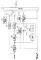
図16は、非特許文献1に記載された技術と特許文献1に記載された技術とを単純に組み合わせて得られる映像符号化装置を示すブロック図である。以下、図16に示す映像符号化装置を一般的な映像符号化装置と呼ぶ。
FIG. 16 is a block diagram showing a video encoding device obtained by simply combining the technique described in
図16を参照して、ディジタル化された映像の各フレームを入力としてビットストリームを出力する一般的な映像符号化装置の構成と動作を説明する。 With reference to FIG. 16, the configuration and operation of a general video encoding apparatus that outputs a bit stream by inputting each frame of a digitized video will be described.
図16に示す映像符号化装置は、画素ビット長増加器101、変換/量子化器102、エントロピー符号化器103、逆変換/逆量子化器104、バッファ105、予測器106、PCM符号化器107、PCM復号器108、多重化データ選択器109、多重化器110、スイッチ121、およびスイッチ122を備える。
16 includes a pixel bit length increaser 101, a transform /
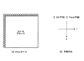
図16に示す映像符号化装置は、フレームをMB(Macro Block :マクロブロック)と呼ばれる16×16画素サイズのブロックに分割し、フレームの左上から順に各MBを符号化する。非特許文献2に記載されているAVCにおいては、MBをさらに4×4画素サイズのブロックにブロック分割し、各4×4ブロックを符号化する。
The video encoding apparatus shown in FIG. 16 divides a frame into blocks of 16 × 16 pixel size called MB (Macro Block), and encodes each MB in order from the upper left of the frame. In AVC described in
図17は、フレームの空間解像度がQCIF(Quarter Common Intermediate Format)の場合のブロック分割の例を示す説明図である。以下、説明の簡略化のために、輝度の画素値のみに着目して各構成要素の動作を説明する。 FIG. 17 is an explanatory diagram showing an example of block division when the spatial resolution of a frame is QCIF (Quarter Common Intermediate Format). Hereinafter, for simplification of description, the operation of each component will be described by focusing on only the luminance pixel value.
画素ビット長増加器101は、外部から設定される画素ビット長増加情報に基づいて、ブロック分割された入力映像の画素ビット長を増加させる。入力映像の画素ビット長をbit_depth_luma、画素ビット長増加情報(増加する画素ビット長)をincreased_bit_depth_lumaとすると、画素ビット長増加器101は、入力映像の各画素値を左にincreased_bit_depth_lumaビットシフトする。よって、画素ビット長増加器101の出力データの画素ビット長は、bit_depth_luma+increased_bit_depth_lumaビットとなる。
The pixel bit length increaser 101 increases the pixel bit length of the input video divided into blocks based on pixel bit length increase information set from the outside. If the pixel bit length of the input video is bit_depth_luma and the pixel bit length increase information (increasing pixel bit length) is incremented_bit_depth_luma, the pixel bit length increaser 101 shifts each pixel value of the input video left by incremented_bit_depth_luma bits. Therefore, the pixel bit length of the output data of the pixel
画素ビット長増加器101から出力される画素ビット長増加済み画像は、予測器106から供給される予測信号が減じられた後、変換/量子化器102に入力される。予測信号には、イントラ予測信号とフレーム間予測信号の2種類がある。それぞれの予測信号を説明する。
The pixel bit length increased image output from the pixel
イントラ予測信号は、バッファ105に格納された現在のピクチャと表示時刻が同一である再構築ピクチャの画像に基づいて生成される予測信号である。非特許文献2の8.3.1 Intra_4×4 prediction process for luma sample、8.3.2 Intra_8×8 prediction process for luma samples 、及び8.3.3 Intra_16×16 prediction process for luma samplesを引用すると、イントラ予測については、3種類のブロックサイズのイントラ予測モードIntra_4×4、Intra_8×8、Intra_16×16がある。
The intra prediction signal is a prediction signal generated based on an image of a reconstructed picture having the same display time as the current picture stored in the
図18(a),(c)を参照すると、Intra_4×4とIntra_8×8は、それぞれ4×4ブロックサイズと8×8ブロックサイズのイントラ予測であることが分かる。ただし、図中の丸(○)はイントラ予測に用いる参照画素、つまり、前記現在のピクチャと表示時刻が同一である再構築ピクチャの画素を示す。 18A and 18C, it can be seen that Intra_4 × 4 and Intra_8 × 8 are intra predictions of 4 × 4 block size and 8 × 8 block size, respectively. However, circles (◯) in the figure indicate reference pixels used for intra prediction, that is, pixels of a reconstructed picture having the same display time as the current picture.
Intra_4×4のイントラ予測では、再構築した周辺画素をそのまま参照画素とし、図18(b)に示す9種類の方向に参照画素をパディング(外挿)して予測信号が形成される。Intra_8×8のイントラ予測では、図18(c)における右矢印の下に記載のローパスフィルタ(1/2、1/4、1/2)によって再構築ピクチャの画像の周辺画素を平滑化した画素を参照画素として、図18(b)に示す9種類の方向に参照画素を外挿して予測信号が形成される。 In Intra_4 × 4 intra prediction, the reconstructed peripheral pixel is used as a reference pixel as it is, and the prediction pixel is padded (extrapolated) in nine types of directions shown in FIG. 18B. In Intra_8 × 8 intra prediction, pixels obtained by smoothing the peripheral pixels of the reconstructed picture using the low-pass filters (1/2, 1/4, 1/2) described below the right arrow in FIG. Is used as a reference pixel, and a prediction signal is formed by extrapolating the reference pixel in nine types of directions shown in FIG.
図19(a)を参照すると、Intra_16×16は、16×16ブロックサイズのイントラ予測であることが分かる。図18に示された例と同様に、図19において、図中の丸(○)はイントラ予測に用いる参照画素、つまり、前記現在のピクチャと表示時刻が同一である再構築ピクチャの画素である。Intra_16×16のイントラ予測では、再構築画像の周辺画素をそのまま参照画素として、図19(b)に示す4種類の方向に参照画素を外挿して予測信号が形成される。 Referring to FIG. 19A, it can be seen that Intra — 16 × 16 is an intra prediction with a 16 × 16 block size. Similarly to the example shown in FIG. 18, in FIG. 19, the circle (◯) in the figure is a reference pixel used for intra prediction, that is, a pixel of a reconstructed picture having the same display time as the current picture. . In Intra_16 × 16 intra prediction, the surrounding pixels of the reconstructed image are directly used as reference pixels, and the prediction pixels are extrapolated in four types of directions shown in FIG. 19B.
以下、イントラ予測信号を用いて符号化されるMBをイントラMBと呼ぶ。イントラ予測のブロックサイズをイントラ予測モードと呼ぶ。また、外挿の方向をイントラ予測方向と呼ぶ。 Hereinafter, an MB encoded using an intra prediction signal is referred to as an intra MB. The block size of intra prediction is called an intra prediction mode. Further, the extrapolation direction is referred to as an intra prediction direction.
フレーム間予測信号は、バッファ105に格納された現在のピクチャと表示時刻が異なる再構築ピクチャの画像から生成される予測信号である。以下、フレーム間予測信号を用いて符号化されるMBをインターMBと呼ぶ。インターMBのブロックサイズとして、例えば、16×16、16×8、 8×16、 8×8、8×4、4×8、4×4を選択することができる。
The inter-frame prediction signal is a prediction signal generated from an image of a reconstructed picture having a display time different from that of the current picture stored in the
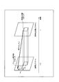
図20は、16×16のブロックサイズを例にしたフレーム間予測の例を示す説明図である。図20に示す動きベクトルMV=(mvx,mvy)は、符号化対象ブロックに対する参照ピクチャのフレーム間予測ブロック(フレーム間予測信号)の平行移動量を示す、フレーム間予測の予測パラメータの一つである。AVCにおいては、符号化対象ブロックの符号化対象ピクチャに対するフレーム間予測信号の参照ピクチャの方向を表すフレーム間予測の方向に加えて、符号化対象ブロックのフレーム間予測に用いる参照ピクチャを同定するための参照ピクチャインデックスもフレーム間予測の予測パラメータである。AVCにおいて、バッファ105に格納された複数枚の参照ピクチャをフレーム間予測に利用できるからである。
FIG. 20 is an explanatory diagram illustrating an example of inter-frame prediction using a 16 × 16 block size as an example. A motion vector MV = (mv x , mv y ) illustrated in FIG. 20 is one of prediction parameters for inter-frame prediction indicating the amount of translation of the inter-frame prediction block (inter-frame prediction signal) of the reference picture with respect to the encoding target block. One. In AVC, in order to identify the reference picture used for the inter-frame prediction of the encoding target block in addition to the inter-frame prediction direction indicating the direction of the reference picture of the inter-frame prediction signal with respect to the encoding target picture of the encoding target block. The reference picture index is also a prediction parameter for inter-frame prediction. This is because in AVC, a plurality of reference pictures stored in the
なお、フレーム間予測のより詳細な説明が、非特許文献2の8.4 Inter prediction processに記載されている。
A more detailed explanation of inter-frame prediction is described in 8.4 Inter prediction process of
以下、フレーム間予測信号を用いて符号化されるMBをインターMBと呼ぶ。フレーム間予測のブロックサイズをインター予測モードという。また、フレーム間予測の方向をインター予測方向と呼ぶ。 Hereinafter, an MB encoded using an inter-frame prediction signal is referred to as an inter MB. The block size for inter-frame prediction is called inter prediction mode. Also, the direction of inter-frame prediction is referred to as an inter prediction direction.
なお、イントラMBのみで符号化されたピクチャはIピクチャと呼ばれる。イントラMBだけでなくインターMBも含めて符号化されたピクチャはPピクチャと呼ばれる。フレーム間予測に1枚の参照ピクチャだけでなく、さらに同時に2枚の参照ピクチャを用いるインターMBを含めて符号化されたピクチャはBピクチャと呼ばれる。また、Bピクチャにおいて、符号化対象ブロックの符号化対象ピクチャに対するフレーム間予測信号の参照ピクチャの方向が過去のフレーム間予測を前方向予測、符号化対象ブロックの符号化対象ピクチャに対するフレーム間予測信号の参照ピクチャの方向が未来のフレーム間予測を後方向予測、過去と未来を含むフレーム間予測を双方向予測と呼ぶ。 Note that a picture encoded only with an intra MB is called an I picture. A picture coded including not only an intra MB but also an inter MB is called a P picture. A picture that is encoded including inter MBs that use not only one reference picture but also two reference pictures at the same time for inter-frame prediction is called a B picture. Further, in the B picture, the reference picture direction of the inter-frame prediction signal with respect to the encoding target picture of the encoding target block is the forward prediction with respect to the past inter-frame prediction, and the inter-frame prediction signal with respect to the encoding target picture of the encoding target block. Inter-frame prediction in which the direction of the reference picture is the future is referred to as backward prediction, and inter-frame prediction including the past and future is referred to as bidirectional prediction.
変換/量子化器102は、予測信号が減じられた画素ビット長増加済み画像(予測誤差画像)を周波数変換する。
The transformer /
さらに、変換/量子化器102は、画素ビット長増加器101が増加させた画素ビット長increased_bit_depth_lumaに応じた量子化ステップ幅Qs で、周波数変換した予測誤差画像(周波数変換係数)を量子化する。通常の量子化ステップ幅をQsluma とすると、例えば、Qs =Qsluma *2increased_bit_depth_lumaとする。以下、量子化された周波数変換係数を変換量子化値と呼ぶ。
Further, the transform /
エントロピー符号化器103は、予測パラメータと変換量子化値をエントロピー符号化する。予測パラメータとは、上述したイントラMB/インターMB、イントラ予測モード、イントラ予測方向、インターMBブロックサイズ、および動きベクトルなど、MBの予測に関連した情報である。
The
逆変換/逆量子化器104は、画素ビット長増加器101が増加させた画素ビット長increased_bit_depth_lumaに応じた量子化ステップ幅で、変換量子化値を逆量子化する。さらに、逆変換/逆量子化器104は、逆量子化した周波数変換係数を逆周波数変換する。逆周波数変換された再構築予測誤差画像は、予測信号が加えられて、スイッチ122に供給される。
The inverse transform /
多重化データ選択器109は、エントロピー符号化器103に対する所定の符号化単位(例えば、マクロブロック)の入力データ量を監視する。所定の符号化単位に対応する処理時間内でエントロピー符号化器103がその入力データをエントロピー符号化可能な場合には、多重化データ選択器109は、エントロピー符号化器103の出力データを選択するようにスイッチ121を制御する。その結果、エントロピー符号化器103の出力データが、スイッチ121を介して多重化器110に供給される。さらに、多重化データ選択器109は、逆変換/量子化器104の出力データを選択するようにスイッチ122を制御する。その結果、逆変換/量子化器104の出力データが、スイッチ122を介してバッファ105に供給される。
The multiplexed
処理時間内でエントロピー符号化可能でない場合には、多重化データ選択器109は、画素ビット長増加器101の出力データをPCM符号化したPCM符号化器107の出力データを選択するようにスイッチ121を制御する。その結果、PCM符号化器107の出力データが、スイッチ121を介して多重化器110に供給される。さらに、多重化データ選択器109は、PCM符号化器107の出力データをPCM復号したPCM復号器108の出力データを選択するようにスイッチ122を制御する。その結果、PCM復号器108の出力データが、スイッチ122を介してバッファ105に供給される。
When entropy encoding is not possible within the processing time, the multiplexed
バッファ105は、スイッチ122を介して供給される再構築画像を格納する。1フレーム分の再構築画像を再構築ピクチャと呼ぶ。
The
多重化器110は、画素ビット長増加情報、およびエントロピー符号化器103の出力データとPCM符号化器107の出力データを多重化して出力する。
The
上述した動作に基づいて、一般的な映像符号化装置はビットストリームを生成する。 Based on the above-described operation, a general video encoding device generates a bit stream.
上述した、一般的な技術を用いた場合に、イントラ予測やフレーム間予測の演算精度を画素ビット長拡張によって高めることと、映像符号化装置や映像復号装置がある一定の処理時間を保証することとを両立できる。 When using the general techniques described above, the calculation accuracy of intra prediction and inter-frame prediction is improved by extending the pixel bit length, and a certain processing time is ensured for the video encoding device and the video decoding device. And both.
しかし、上述した一般的な技術においては、画素ビット長増加させた画像をPCM符号化する。すると、PSNR(Peak Signal to Noise Ratio )改善が得られないにも関わらず、画素ビット長増加分だけPCM符号化の出力データが増加するという課題がある。例えば、bit_depth_lumaが8ビット、increased_bit_depth_lumaが8ビットである場合、PCM符号化の出力データ量は入力画像8ビットの2倍の16ビットになる。 However, in the general technique described above, an image with an increased pixel bit length is PCM encoded. Then, although PSNR (Peak Signal to Noise Ratio) improvement cannot be obtained, there is a problem that the output data of PCM coding increases by the increase of the pixel bit length. For example, when bit_depth_luma is 8 bits and increased_bit_depth_luma is 8 bits, the output data amount of PCM encoding is 16 bits, which is twice the 8-bit input image.
そこで、本発明は、画素ビット長増加と非圧縮符号化に基づいた映像符号化において、非圧縮符号化の出力データの増加を抑制することを目的とする。 Accordingly, an object of the present invention is to suppress an increase in output data of uncompressed encoding in video encoding based on an increase in pixel bit length and uncompressed encoding.
本発明による映像復号装置は、ビットストリームに含まれる画像の変換データをエントロピー復号するエントロピー復号手段と、ビットストリームに含まれる画像の非圧縮符号化データを非圧縮復号する非圧縮復号手段と、非圧縮復号したデータの画素ビット長を増加させる画素ビット長増加手段と、エントロピー復号手段および非圧縮復号手段を制御する復号制御手段とを備え、画素ビット長増加手段は、非圧縮復号手段の入力データに対応する画像の画素ビット長を、エントロピー復号手段の入力データに対応する画像の画素ビット長に揃えることを特徴とする。 An image decoding apparatus according to the present invention includes an entropy decoding unit that entropy decodes converted data of an image included in a bitstream, an uncompressed decoding unit that performs uncompressed decoding of uncompressed encoded data of an image included in the bitstream, A pixel bit length increasing means for increasing the pixel bit length of the compressed and decoded data; and a decoding control means for controlling the entropy decoding means and the uncompressed decoding means. The pixel bit length increasing means comprises input data of the uncompressed decoding means. The pixel bit length of the image corresponding to is matched with the pixel bit length of the image corresponding to the input data of the entropy decoding means.
本発明による映像復号方法は、ビットストリームに含まれる画像の変換データをエントロピー復号し、ビットストリームに含まれる画像の非圧縮符号化データを非圧縮復号し、エントロピー復号と非圧縮復号とを制御し、非圧縮復号の入力データに対応する画像の画素ビット長が、エントロピー復号の入力データに対応する画像の画素ビット長と揃うように、非圧縮復号の入力データに対応する画像の画素ビット長を増加させることを特徴とする。 The video decoding method according to the present invention controls the entropy decoding and the uncompressed decoding by entropy decoding the converted data of the image included in the bit stream, uncompressed the uncompressed encoded data of the image included in the bit stream. The pixel bit length of the image corresponding to the uncompressed decoding input data is set so that the pixel bit length of the image corresponding to the uncompressed decoding input data is aligned with the pixel bit length of the image corresponding to the entropy decoding input data. It is characterized by increasing.
本発明による映像復号プログラムは、コンピュータに、ビットストリームに含まれる画像の変換データをエントロピー復号する処理と、ビットストリームに含まれる画像の非圧縮符号化データを非圧縮復号する処理と、エントロピー復号と非圧縮復号とを制御する処理と、非圧縮復号の入力データに対応する画像の画素ビット長が、エントロピー復号の入力データに対応する画像の画素ビット長と揃うように、非圧縮復号の入力データに対応する画像の画素ビット長を増加させる処理とを実行させることを特徴とする。 A video decoding program according to the present invention includes a computer that performs entropy decoding on image conversion data included in a bitstream, non-compression decoding on uncompressed encoded data included in the bitstream, and entropy decoding. Input data for uncompressed decoding so that the pixel bit length of the image corresponding to the input data for uncompressed decoding matches the pixel bit length of the image corresponding to the input data for entropy decoding. And a process of increasing the pixel bit length of the image corresponding to.
本発明によれば、画素ビット長増加と非圧縮符号化に基づいた映像符号化において、非圧縮符号化の出力データの増加を抑制することができる。 According to the present invention, it is possible to suppress an increase in output data of uncompressed encoding in video encoding based on an increase in pixel bit length and uncompressed encoding.
実施形態1.
本実施形態の映像符号化装置は、エントロピー符号化の出力データとPCM符号化の出力データのそれぞれに対応する画像の画素ビット長を互いに異ならせる手段、画素ビット長増加情報に基づいてPCM復号の復号画像の画素ビット長を増加させる手段、および画素ビット長増加情報をビットストリームに多重化する手段を備える。
The video encoding apparatus of the present embodiment is a means for differentiating pixel bit lengths of images corresponding to output data of entropy encoding and output data of PCM encoding, and PCM decoding based on pixel bit length increase information. Means for increasing the pixel bit length of the decoded image, and means for multiplexing the pixel bit length increase information into the bit stream.
図1に示すように、本実施の形態の映像符号化装置は、図16に示された一般的な映像符号化装置が備えていた画素ビット長増加器101、変換/量子化器102、エントロピー符号化器103、逆変換/逆量子化器104、バッファ105、予測器106、PCM符号化器107、PCM復号器108、多重化データ選択器109、多重化器110、スイッチ121、およびスイッチ122に加えて、画素ビット長増加情報に基づいてPCM復号器108の復号画像の画素ビット長を増加させるための画素ビット長増加器111を備える。
As shown in FIG. 1, the video encoding apparatus according to the present embodiment includes a pixel
また、図1と図16とを比較すると、本実施形態の映像符号化装置は、エントロピー符号化の出力データとPCM符号化の出力データのそれぞれに対応する画像の画素ビット長を互いに異ならせるために、画素ビット長を増加させる前の入力画像をPCM符号化器107に供給することが分かる。なお、前記エントロピー符号化の出力データに対応する画像とは、変換/量子化器102に供給される画素ビット長増加された入力映像の画像、および、逆変換/逆量子化器104から供給される前記画素ビット長増加された入力映像の画像の再構築画像である。また、前記PCM符号化の出力データに対応する画像とは、PCM符号化器107に供給される画素ビット長増加されていない入力映像の画像、および、PCM復号器108から供給される前記画素ビット長増加されていない入力映像のPCM復号画像である。
Also, comparing FIG. 1 with FIG. 16, the video encoding apparatus according to the present embodiment is different in that the pixel bit lengths of the images corresponding to the entropy-encoded output data and the PCM-encoded output data are different from each other. In addition, it can be seen that the input image before the pixel bit length is increased is supplied to the
画素ビット長増加器101は、外部から設定される画素ビット長増加情報に基づいて、ブロック分割された入力映像の画素ビット長を増加させる。
The pixel
入力映像の輝度の画素ビット長をbit_depth_luma、輝度の画素ビット長増加情報(増加する画素ビット長)をincreased_bit_depth_lumaとすると、画素ビット長増加器101は、入力映像の輝度の各画素値を左にincreased_bit_depth_lumaビットシフトする。よって、画素ビット長増加器101の出力データの画素ビット長は、bit_depth_luma+increased_bit_depth_lumaビットとなる。同様に、色差(CbとCrの成分)については、入力映像の色差の画素ビット長をbit_depth_chroma、色差の画素ビット長増加情報をincreased_bit_depth_chromaとすると、画素ビット長増加器101は、入力映像の色差の各画素値を左にincreased_bit_depth_lumaビットシフトする。
If the pixel bit length of the luminance of the input video is bit_depth_luma and the increase information of the pixel bit length of the luminance (increased pixel bit length) is incremented_bit_depth_luma, the pixel
画素ビット長増加器101から出力される画素ビット長増加済み画像は、予測器106から供給される予測信号が減じられて、変換/量子化器102に入力される。変換/量子化器102は、予測信号が減じられた画素ビット長増加済み画像(予測誤差画像)を周波数変換する。
The pixel bit length increased image output from the pixel
さらに、変換/量子化器102は、画素ビット長増加器101が増加させた画素ビット長increased_bit_depth_lumaおよびincreased_bit_depth_chromaに応じた量子化ステップ幅Qs で、周波数変換した予測誤差画像(周波数変換係数)を量子化する。通常の輝度の量子化ステップ幅をQsluma とすると、例えば、Qs =Qsluma *2increased_bit_depth_lumaとする。以後、量子化された周波数変換係数を変換量子化値と呼ぶ。
Further, the transform /
エントロピー符号化器103は、予測器106から供給される予測パラメータと変換/量子化器102から供給される変換量子化値をエントロピー符号化する。予測パラメータとは、イントラMB/インターMB、イントラ予測モード、イントラ予測方向、インターMBブロックサイズ、および、動きベクトルなど、マクロブロックの予測に関連した情報である。
The
逆変換/逆量子化器104は、画素ビット長増加器101が増加させた画素ビット長increased_bit_depth_lumaおよびincreased_bit_depth_chromaに応じた量子化ステップ幅で、変換量子化値を逆量子化する。さらに、逆変換/逆量子化器104は、逆量子化した周波数変換係数を逆周波数変換する。逆周波数変換された再構築予測誤差画像は、予測信号が加えられて、スイッチ122に供給される。
The inverse transform /
PCM符号化器107は、画素ビット長を増加させる前の入力画像をPCM符号化する。PCM符号化器107の輝度の出力データpcm_sample_luma[i]は、入力映像の輝度の画素ビット長bit_depth_lumaとなる。ただし、i(0≦i≦255)は該マクロブロック内のラスタスキャン順でのインデックスである。同様に、PCM符号化器107の色差の出力データpcm_sample_chroma[i] (i:0≦i≦127)は、入力映像の色差の画素ビット長bit_depth_chromaとなる。
The
PCM復号器108は、pcm_sample_luma[i]およびpcm_sample_croma[i] をPCM復号する。以下、PCM復号を、PCMデータ読み込みと呼ぶことがある。
The
画素ビット長増加器111は、PCMデータ読み込みしたpcm_sample_luma[i]を左にincreased_bit_depth_lumaビットシフトする。よって、PCM復号器108を介して得られた再構築画像は、bit_depth_luma+increased_bit_depth_lumaビットとなって、スイッチ122に供給される。同様に、PCMデータ読み込みしたpcm_sample_chroma[i]は左にincreased_bit_depth_chromaビットシフトされて、スイッチ122に供給される。
The pixel
多重化データ選択器109は、エントロピー符号化器103に対する所定の符号化単位(例えば、マクロブロック)の入力データ量を監視する。所定の符号化単位に対応する処理時間内でエントロピー符号化器103がその入力データをエントロピー符号化可能な場合には、多重化データ選択器109は、エントロピー符号化器103の出力データを選択するようにスイッチ121を制御する。その結果、エントロピー符号化器103の出力データが、スイッチ121を介して多重化器110に供給される。さらに、多重化データ選択器109は、逆変換/量子化器104の出力データを選択するようにスイッチ122を制御する。その結果、逆変換/量子化器104の出力データが、スイッチ122を介してバッファ105に供給される。
The multiplexed
処理時間内でエントロピー符号化可能でない場合には、多重化データ選択器109は、まず、該マクブロックがPCMのイントラMBであることを示す情報をエントロピー符号化器103に符号化出力させる。具体的には、非特許文献2の7.3.5 Macroblock layer syntax に従うと、mb_type をI_PCM としてエントロピー符号化出力させる。
If entropy encoding is not possible within the processing time, the multiplexed
続いて、エントロピー符号化器103の出力ビットをバイトアラインする。具体的には、非特許文献2の7.3.5 Macroblock layer syntax に従うと、エントロピー符号化器103が、所定量のpcm_alignment_zero_bitを多重化器110に供給する。また、以後の符号化のために、エントロピー符号化器103が符号化エンジンを初期化する。
Subsequently, the output bits of the
なお、符号化エンジン初期化の一例が、非特許文献2の9.3.4.1 Initialization process for the arithmetic encoding engine (informative )に記載されている。
An example of encoding engine initialization is described in 9.3.4.1 Initialization process for the arithmetic encoding engine (informative) of
さらに、多重化データ選択器109は、PCM符号化器107の出力データを選択するようにスイッチ121を制御する。その結果、PCM符号化器107の出力データが、スイッチ121を介して多重化器110に供給される。
Further, the multiplexed
最後に、多重化データ選択器109は、画素ビット長増加器111の出力データを選択するようにスイッチ122を制御する。その結果、画素ビット長増加器111の出力データが、スイッチ122を介してバッファ105に供給される。なお、画素ビット長増加器111は、PCM符号化器107の出力データpcm_sample_luma[i]を読み込んだPCM復号器108の出力データpcm_sample_luma[i]を左にincreased_bit_depth_lumaビットシフトしてビット数を増やしている。同様に、画素ビット長増加器111は、PCM符号化器107の出力データpcm_sample_chroma[i]を読み込んだPCM復号器108の出力データpcm_sample_ chroma [i]を左にincreased_bit_depth_chromaビットシフトしてビット数を増やしている。
Finally, the multiplexed
多重化器110は、画素ビット長増加情報、およびエントロピー符号化器103の出力データとPCM符号化器107の出力データを多重化して出力する。非特許文献2のSpecification of syntax functions, categories, and descriptorsに従うと、図2に示すリストに記載されているように、シーケンスパラメータのbit_depth_luma_minus8 とbit_depth_chroma_minus8 に後続させて、画素ビット長増加情報(increased_bit_depth_lumaおよびincreased_bit_depth_chroma)を多重化することが考えられる。ただし、bit_depth_luma_minus8 は入力映像の輝度の画素ビット長bit_depth_lumaから8を減じた値、bit_depth_chroma_minus8 は入力映像の色差の画素ビット長bit_depth_chromaから8を減じた値、increased_bit_depth_lumaは輝度の増加画素ビット長、そして、increased_bit_depth_chromaは色差の増加画素ビット長である。
The
なお、図2に示すリストにおける表記(”C”や”Descriptor”)については、例えば、非特許文献2の7.2 Specification of syntax functions, categories, and descriptorsに従うとする。
Note that the notation (“C” and “Descriptor”) in the list shown in FIG. 2 conforms to 7.2 Specification of syntax functions, categories, and descriptors of
上述した動作に基づいて、本実施形態の映像符号化装置はビットストリームを生成する。 Based on the above-described operation, the video encoding apparatus according to the present embodiment generates a bit stream.
次に、本発明の特徴である処理時間内でエントロピー符号化することが可能でない場合のエントロピー符号化器103、PCM符号化器107、PCM復号器108および画素ビット長増加器111の動作を図3のフローチャートを参照して説明する。
Next, operations of the
図3に示すように、ステップS101では、映像符号化装置や映像復号装置にある一定の処理時間を保証させるために、エントロピー符号化器103が、mb_typeをI_PCMとしてエントロピー符号化し多重化器110に供給する。
As shown in FIG. 3, in step S101, the
ステップS102では、エントロピー符号化器103が、出力ビットをバイトアラインさせるために、pcm_alignment_zero_bitを多重化器110に供給する。
In step S102, the
ステップS103では、以降のエントロピー符号化のために、エントロピー符号化器103が符号化エンジンを初期化する。
In step S103, the
ステップS104では、PCM符号化の出力データを増加させないように、画素ビット長を増加させる前の入力画像をPCM符号化器107がPCM符号化し多重化器110に供給する。
In step S <b> 104, the
ステップS105では、PCM復号器108が、PCM符号化の結果pcm_sample_luma[i]およびpcm_sample_chroma[i]をPCM復号(PCMデータ読み込み)する。
In step S105, the
ステップS106では、以降のイントラ予測やフレーム間予測の演算精度を高めるために、画素ビット長増加器111が、PCM復号器108がPCMデータ読み込みしたpcm_sample_luma[i]とpcm_sample_chroma[i]を左にそれぞれincreased_bit_depth_lumaとincreased_bit_depth_chromaでビットシフトする。
In step S106, in order to improve the calculation accuracy of the subsequent intra prediction and inter-frame prediction, the pixel
以上のように、所定の符号化単位に対応する処理時間内でエントロピー符号化を行うことが可能でない場合において、エントロピー符号化器103およびPCM符号化器107の動作が実行される。
As described above, when entropy coding cannot be performed within the processing time corresponding to a predetermined coding unit, the operations of the
本実施形態の映像符号化装置では、エントロピー符号化の出力データとPCM符号化の出力データのそれぞれに対応する画像の画素ビット長を互いに異ならせるために、画素ビット長を増加させる前の入力画像がPCM符号化器107に供給される。そのような構成に基づいて、画素ビット長増加と非圧縮符号化とに基づいた映像符号化において、PCM符号化の出力データの増加を抑制できる。
In the video encoding device of the present embodiment, the input image before the pixel bit length is increased in order to make the pixel bit lengths of the images corresponding to the output data of entropy encoding and the output data of PCM encoding differ from each other. Is supplied to the
また、本実施形態の映像符号化装置は、画素ビット長増加情報に基づいて、PCM復号の復号画像の画素ビット長を増加させる画素ビット長増加器111を備える。画素ビット長増加器111によって、画素ビット長を異ならせることに起因する、イントラ予測やフレーム間予測の演算精度低下を抑制できる。
The video encoding apparatus according to the present embodiment further includes a pixel
さらに、本実施形態の映像符号化装置では、多重化器110は、映像復号でも同様にPCM復号の復号画像の画素ビット長を増加させるために、画素ビット長増加情報をビットストリームに多重化する。そのような構成に基づいて、映像符号化装置と映像復号装置の相互運用性を高めることができる。すなわち、映像符号化装置と映像復号装置とが共動して、システムにおけるPCM符号化の増加を抑制できるとともに、イントラ予測やフレーム間予測の演算精度低下を抑制できる。
Further, in the video encoding device of the present embodiment, the
実施形態2.
本実施形態の映像復号装置では、エントロピー復号手段とPCM復号手段のそれぞれの入力データに対応する画像の画素ビット長が互いに異なるビットストリームを復号する。なお、前記エントロピー復号手段の入力データに対応する画像とは、後述する逆変換/逆量子化器206から供給される画素ビット長増加された入力映像の画像の再構築画像である。また、前記PCM復号手段の入力データに対応する画像とは、後述するPCM復号器203から供給される画素ビット長増加されていない入力映像のPCM復号画像である。
In the video decoding apparatus according to the present embodiment, bit streams having different pixel bit lengths of images corresponding to input data of the entropy decoding unit and the PCM decoding unit are decoded. The image corresponding to the input data of the entropy decoding means is a reconstructed image of an input video image with an increased pixel bit length supplied from an inverse transform /
図4に示すように、本実施の形態の映像復号装置は、多重化解除器201、復号制御器202、PCM復号器203、エントロピー復号器204、画素ビット長増加器205、逆変換/逆量子化器206、予測器207、バッファ208、画素ビット長減少器209、スイッチ221、およびスイッチ222を備える。
As shown in FIG. 4, the video decoding apparatus according to the present embodiment includes a
多重化解除器201は、入力されるビットストリームを多重化解除して、画素ビット長増加情報、およびエントロピー符号化もしくはPCM符号化された映像ビットストリームを抽出する。非特許文献2のSpecification of syntax functions, categories, and descriptorsに従うと、図2に示すリストに記載されているようにシーケンスパラメータのbit_depth_luma_minus8 とbit_depth_chroma_minus8 に後続する、画素ビット長増加情報(increased_bit_depth_lumaおよびincreased_bit_depth_chroma)を抽出する。
The
エントロピー復号器204は、映像ビットストリームをエントロピー復号する。マクロブロックのmb_type がI_PCM (PCM符号化)ではない場合には、エントロピー復号器204は、該マクロブロックの予測パラメータおよび変換量子化値をエントロピー復号して、逆変換/逆量子化器206および予測器207に供給する。
The
逆変換/逆量子化器206は、多重化解除によって抽出した画素ビット長増加情報increased_bit_depth_lumaおよびincreased_bit_depth_chromaに応じた量子化ステップ幅で、輝度および色差の変換量子化値を逆量子化する。さらに、逆変換/逆量子化器206は、逆量子化した周波数変換係数を逆周波数変換する。
The inverse transform /
予測器207は、エントロピー復号した予測パラメータに基づいて、バッファ208に格納された再構築ピクチャの画像を用いて予測信号を生成する。
The
逆変換/逆量子化器206で逆周波数変換された再構築予測誤差画像は、予測器207から供給される予測信号が加えられた後、スイッチ222に供給される。
The reconstructed prediction error image subjected to inverse frequency conversion by the inverse transformer /
復号制御器202は、予測信号が加えられた再構築予測誤差画像が再構築画像としてバッファ208に供給されるようにスイッチ222を切り替える。
The
マクロブロックのmb_type がPCM符号化の場合、復号制御器202は、多重化解除器201に、エントロピー復号途中の映像ビットストリームをバイトアラインさせる。非特許文献2の7.3.5 Macroblock layer syntaxに従うと、多重化解除器201に、映像ビットストリームがバイトアラインするまでpcm_alignment_zero_bitを読み出させる。
When the mb_type of the macroblock is PCM encoding, the
次に、復号制御器202は、エントロピー復号器204の復号エンジンを初期化させる。なお、復号エンジン初期化の一例が、非特許文献2の9.3.1.2 Initialization process for the arithmetic decoding engineに記載されている。
Next, the
続いて、復号制御器202は、バイトアラインした映像ビットストリームがPCM復号器203に供給されるようにスイッチ221を切り替える。
Subsequently, the
PCM復号器203は、バイトアラインした映像ビットストリームからPCM符号化された輝度データpcm_sample_luma[i]および色差データpcm_sample_chroma[i]をPCM復号(PCMデータ読み込み)する。
The
画素ビット長増加器205は、多重化解除によって抽出された画素ビット長増加情報increased_bit_depth_lumaとincreased_bit_depth_chromaに従って、PCMデータ読み込みしたpcm_sample_luma[i]とpcm_sample_chroma[i]をそれぞれ左にビットシフトする。非特許文献2の8.3.5 Sample construction process for I_PCM macroblocks の記述に従うと、PCM復号輝度画像S'LおよびPCM復号色差画像S'CbとS'Crは、以下の式(8-154’)および式(8-155’)によって計算される。
The pixel
for(i = 0; i < 256; i++ )
S'L[ xP + ( i % 16), yP + dy * ( i / 16)) ] = (pcm_sample_luma[ i ]<<increased_bit_depth_luma) (8-154')
for (i = 0; i <256; i ++)
S'L [xP + (i% 16), yP + dy * (i / 16))] = (pcm_sample_luma [i] << increased_bit_depth_luma) (8-154 ')
for( i = 0; i < MbWidthC * MbHeightC; i++ ) {
S'Cb[ ( xP / SubWidthC ) + ( i % MbWidthC ), ( ( yP + SubHeightC − 1) / SubHeightC ) + dy * ( i / MbWidthC ) ] =
(pcm_sample_chroma[ i ]<< increased_bit_depth_chroma)
S'Cr[ ( xP / SubWidthC ) + ( i % MbWidthC ),( ( yP + SubHeightC − 1 ) / SubHeightC ) + dy * ( i / MbWidthC ) ] =
(pcm_sample_chroma[ i + MbWidthC * MbHeightC ]<< increased_bit_depth_chroma)
} (8-155’)
for (i = 0; i <MbWidthC * MbHeightC; i ++) {
S'Cb [(xP / SubWidthC) + (i% MbWidthC), ((yP + SubHeightC − 1) / SubHeightC) + dy * (i / MbWidthC)] =
(pcm_sample_chroma [i] << increased_bit_depth_chroma)
S'Cr [(xP / SubWidthC) + (i% MbWidthC), ((yP + SubHeightC − 1) / SubHeightC) + dy * (i / MbWidthC)] =
(pcm_sample_chroma [i + MbWidthC * MbHeightC] << increased_bit_depth_chroma)
} (8-155 ')
復号制御器202は、画素ビット長を増加させたPCM復号画像が再構築画像としてバッファ208に供給されるようにスイッチ222を切り替える。次マクロブロックの復号のために、復号制御器202は、多重化解除器201の出力データがエントロピー復号器204に供給されるようにスイッチ221を切り替える。
The
画素ビット長減少器209は、多重化解除によって抽出された画素ビット長増加情報increased_bit_depth_lumaおよびincreased_bit_depth_chromaに従って、バッファ208に格納された再構築ピクチャの画素ビット長を減少させて出力する。
The pixel
上述した動作に基づいて、本実施形態の映像復号装置はデコード画像を生成する。 Based on the above-described operation, the video decoding apparatus according to the present embodiment generates a decoded image.
次に、発明の特徴であるマクロブロックのmb_type がPCM符号化の場合での復号制御器202、エントロピー復号器204、PCM復号器203および画素ビット長増加器205の動作を図5のフローチャートを参照して説明する。
Next, the operations of the
ステップS201では、多重化解除器201は、エントロピー復号途中の映像ビットストリームをバイトアラインさせるため、pcm_alignment_zero_bitを読み取る。
In step S201, the
ステップS202では、以降のエントロピー復号のために、エントロピー復号器204が復号エンジンを初期化する。
In step S202, the
ステップS203では、PCM復号器203が、PCM符号化の結果pcm_sample_luma[i]およびpcm_sample_chroma[i]をPCM復号(PCMデータ読み込み)する。
In step S203, the
ステップS204では、以降のイントラ予測やフレーム間予測の演算精度を高めるために、画素ビット長増加器205が、PCMデータ読み込みしたpcm_sample_luma[i]とpcm_sample_chroma[i]を左にそれぞれincreased_bit_depth_lumaとincreased_bit_depth_chromaでビットシフトする。
In step S204, in order to improve the calculation accuracy of the subsequent intra prediction and inter-frame prediction, the pixel
以上のように、マクロブロックのmb_type がPCM符号化の場合において、復号制御器202、エントロピー復号器204、PCM復号器203および画素ビット長増加器205の動作が実行される。
As described above, when the mb_type of the macroblock is PCM encoding, the operations of the
本実施形態の映像復号装置は、多重化解除によって抽出された画素ビット長増加情報に基づいて、PCM復号の復号画像の画素ビット長を増加させる画素ビット長増加器205を備える。画素ビット長増加器205を備えることによって、エントロピー復号手段とPCM復号手段のそれぞれの入力に対応する画像の画素ビット長を異ならせることに起因する、イントラ予測やフレーム間予測の演算精度低下を抑制できる。また、映像復号と同一の再構築画像が得られるので、映像符号化装置と映像復号装置の相互運用性を高めることができる。すなわち、映像符号化装置と映像復号装置とが共動して、システムにおけるPCM符号化の増加を抑制できるとともに、イントラ予測やフレーム間予測の演算精度低下を抑制できる。
The video decoding apparatus of this embodiment includes a pixel
図1に示された第1実施形態の映像符号化装置は、エントロピー符号化の出力データとPCM符号化の出力データのそれぞれに対応する画像の画素ビット長を互いに異ならせるために、画素ビット長を増加させる前の入力画像をPCM符号化器107に供給する映像符号化装置であった。
The video encoding apparatus according to the first embodiment shown in FIG. 1 uses a pixel bit length in order to make the pixel bit lengths of images corresponding to output data of entropy encoding and output data of PCM encoding different from each other. This is a video encoding device that supplies the input image before the increase to the
図6は、図1に示された映像符号化装置と同等の効果を奏する他の構成の映像符号化装置を示すブロック図である。 FIG. 6 is a block diagram showing a video encoding device having another configuration that achieves the same effect as the video encoding device shown in FIG.
図1に示された映像符号化装置と比較すると、図6に示す映像符号化装置には、画素ビット長減少器112が追加されている。すなわち、図6に示す映像符号化装置では、画素ビット長増加した画像を入力する画素ビット長減少器112が、画素ビット長増加情報に基づいて画素ビット長減少させた画像をPCM符号化器107に供給する構成となっている。第1の実施形態と同様に、図6に示す映像符号化装置は、PCM符号化の出力データの増加を抑制でき、かつ、画素ビット長を異ならせることに起因するイントラ予測やフレーム間予測の演算精度低下を抑制できる。
Compared with the video encoding device shown in FIG. 1, a pixel
また、上記の各実施形態では、再構築ピクチャの画素は画素ビット長増加された画素である。しかし、再構築ピクチャを格納するバッファサイズを削減するために、バッファの入出力に上記の画素ビット長増加器および画素ビット長減少器を利用する実施形態も考えられる。そのような実施形態においても、本発明によれば、PCM符号化の出力データの増加抑制、及び、前記画素ビット長を互いに異ならせることに起因する、イントラ予測の演算精度低下抑制を両立できる。 In each of the above embodiments, the pixel of the reconstructed picture is a pixel with an increased pixel bit length. However, in order to reduce the size of the buffer for storing the reconstructed picture, an embodiment using the above-described pixel bit length increaser and pixel bit length decreaser for input / output of the buffer is also conceivable. Even in such an embodiment, according to the present invention, it is possible to achieve both suppression of increase in output data of PCM encoding and suppression of reduction in calculation accuracy of intra prediction caused by making the pixel bit lengths different from each other.
また、上記の各実施形態では、PCM復号器と画素ビット長増加器とは独立した機能ブロックであった。しかし、式(8-154’)および式(8-155’)から容易に類推できるように、PCM復号器と画素ビット長増加器とを統合して一つの機能ブロックとすることも可能である。 In the above embodiments, the PCM decoder and the pixel bit length increaser are independent functional blocks. However, it is also possible to integrate the PCM decoder and the pixel bit length increaser into one functional block so that it can be easily inferred from the equations (8-154 ′) and (8-155 ′). .
また、上記の各実施形態では、映像符号化装置は、明示的に画素ビット長増加情報を映像復号装置にシグナリングするために、bit_depth_luma_minus8 とbit_depth_chroma_minus8 に後続して、increased_bit_depth_lumaおよびincreased_bit_depth_chromaをビットストリームに多重化した(図2参照)。しかし、映像符号化装置は、暗黙的に画素ビット長増加情報を映像復号装置にシグナリングするために、画素ビット長増加情報として画素ビット長増加後の画素ビット長情報をそのままビットストリームに多重化することも可能である(ただし、映像符号化装置と映像復号装置において、入力映像の元の画素ビット長を例えば8ビットと想定する。)。 In each of the above embodiments, the video encoding apparatus multiplexes incremented_bit_depth_luma and increased_bit_depth_chroma into a bitstream following bit_depth_luma_minus8 and bit_depth_chroma_minus8 in order to explicitly signal the pixel bit length increase information to the video decoding apparatus. (See FIG. 2). However, in order to implicitly signal the pixel bit length increase information to the video decoding device, the video encoding device multiplexes the pixel bit length information after the pixel bit length increase as it is into the bit stream as the pixel bit length increase information. (However, in the video encoding device and the video decoding device, the original pixel bit length of the input video is assumed to be, for example, 8 bits).
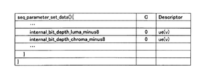
この場合、映像符号化装置は、シーケンスパラメータのbit_depth_luma_minus8 とbit_depth_chroma_minus8 の代わりに、図7に示す画素ビット長増加情報(internal_bit_depth_luma_minus8およびinternal_bit_depth_chroma_minus8)をシーケンスパラメータに多重化する。ただし、internal_bit_depth_luma_minus8 はincreased_bit_depth_lumaの値、internal_bit_depth_chroma_minus8 はincreased_bit_depth_chromaの値である。 In this case, the video encoding apparatus multiplexes the pixel bit length increase information (internal_bit_depth_luma_minus8 and internal_bit_depth_chroma_minus8) illustrated in FIG. 7 into the sequence parameters instead of the sequence parameters bit_depth_luma_minus8 and bit_depth_chroma_minus8. However, internal_bit_depth_luma_minus8 is the value of increased_bit_depth_luma, and internal_bit_depth_chroma_minus8 is the value of increased_bit_depth_chroma.
図7に示す画素ビット長増加情報をシーケンスパラメータに多重化する場合、PCM符号化器107は、画素ビット長を増加させる前の入力画像をPCM符号化する。すなわち、PCM符号化器107は、8ビットのpcm_sample_luma[i]およびpcm_sample_croma[i] をPCM符号化する。PCM復号器108は、8ビットのpcm_sample_luma[i]およびpcm_sample_croma[i] をPCM復号する。画素ビット長増加器111は、PCM復号したpcm_sample_luma[i]とpcm_sample_chroma[i]をそれぞれincreased_bit_depth_lumaとincreased_bit_depth_chromaだけ左にビットシフトする。
When the pixel bit length increase information shown in FIG. 7 is multiplexed with the sequence parameter, the
図7に示す画素ビット長増加情報をシーケンスパラメータに多重化する場合に対応する映像復号装置は、画素ビット長増加情報(internal_bit_depth_luma_minus8およびinternal_bit_depth_chroma_minus8)をシーケンスパラメータから多重化解除し、increased_bit_depth_lumaおよびincreased_bit_depth_chromaを以下のように計算する。 The video decoding apparatus corresponding to the case where the pixel bit length increase information shown in FIG. 7 is multiplexed with the sequence parameter demultiplexes the pixel bit length increase information (internal_bit_depth_luma_minus8 and internal_bit_depth_chroma_minus8) from the sequence parameter, and sets increased_bit_depth_luma and increased_bit_depth_chroma as Calculate as follows.
increased_bit_depth_luma = internal_bit_depth_luma_minus8
increased_bit_depth_chroma = internal_bit_depth_chroma_minus8
increased_bit_depth_luma = internal_bit_depth_luma_minus8
increased_bit_depth_chroma = internal_bit_depth_chroma_minus8
上記の計算によって、映像復号装置は、映像符号化装置が暗黙的にシグナリングした画素ビット長増加情報を多重化解除できる。 Through the above calculation, the video decoding apparatus can demultiplex the pixel bit length increase information implicitly signaled by the video encoding apparatus.
なお、上述した映像符号化装置が暗黙的に画素ビット長増加情報を映像復号装置にシグナリングする場合において、入力映像の元の画素ビット長が8ビットよりも長い場合に無歪みでPCM符号化できなくなる問題がある。例えば、入力映像の元の画素ビット長が10ビットである場合に8ビットのpcm_sample_luma[i]およびpcm_sample_croma[i] では量子化歪みが発生する。 In addition, when the video encoding device described above implicitly signals pixel bit length increase information to the video decoding device, if the original pixel bit length of the input video is longer than 8 bits, PCM encoding can be performed without distortion. There is a problem that disappears. For example, when the original pixel bit length of the input video is 10 bits, quantization distortion occurs in 8-bit pcm_sample_luma [i] and pcm_sample_croma [i].
入力映像の元の画素ビット長がNビット(N>8)である場合に量子化歪みなしのPCM符号化をサポートするために、図8に示すように、PCMのビット長が画素ビット長増加後の画素ビット長であるか否かを示すフラグpcm_sample_bit_depth_is_internal_bit_depth_flag をシーケンスパラメータに追加してもよい。 In order to support PCM coding without quantization distortion when the original pixel bit length of the input video is N bits (N> 8), as shown in FIG. 8, the PCM bit length is increased by the pixel bit length. A flag pcm_sample_bit_depth_is_internal_bit_depth_flag indicating whether or not the pixel bit length is later may be added to the sequence parameter.
pcm_sample_bit_depth_is_internal_bit_depth_flag が0の場合、PCM符号化器107は、画素ビット長を増加させる前の入力画像をPCM符号化する。すなわち、PCM符号化器107は、8ビットのpcm_sample_luma[i]およびpcm_sample_croma[i] をPCM符号化する。PCM復号器108は、8ビットのpcm_sample_luma[i]およびpcm_sample_croma[i] をPCM復号する。また、画素ビット長増加器111は、PCM復号したpcm_sample_luma[i]とpcm_sample_chroma[i]をそれぞれincreased_bit_depth_luma(=internal_bit_depth_luma_minus8)とincreased_bit_depth_chroma(=internal_bit_depth_chroma_minus8 )だけ左にビットシフトする。
When pcm_sample_bit_depth_is_internal_bit_depth_flag is 0, the
pcm_sample_bit_depth_is_internal_bit_depth_flag が1の場合、PCM符号化器107は、画素ビット長を増加した画像をPCM符号化する。すなわち、PCM符号化器107は、Nビット(internal_bit_depth_luma_minus8+8ビット)のpcm_sample_luma[i]およびNビット(internal_bit_depth_chroma_minus8+8ビット)のpcm_sample_croma[i] をPCM符号化する。PCM復号器108は、Nビットのpcm_sample_luma[i]およびNビットのpcm_sample_croma[i]をPCM復号する。また、画素ビット長増加器111は、PCM復号したpcm_sample_luma[i]とpcm_sample_chroma[i] を0ビットだけ左にビットシフトする(すなわち、左にビットシフトをしない)。
When pcm_sample_bit_depth_is_internal_bit_depth_flag is 1, the
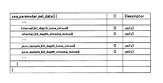
また、入力映像の元の画素ビット長がNビット(N>8)である場合に量子化歪みなしのPCM符号化をサポートするために、pcm_sample_bit_depth_is_internal_bit_depth_flag の代わりに、図9に示すように、輝度および色差それぞれのPCMのビット長pcm_sample_bit_depth_luma_minus8およびpcm_sample_bit_depth_chroma_minus8をシーケンスパラメータに追加してもよい。 In addition, in order to support PCM coding without quantization distortion when the original pixel bit length of the input video is N bits (N> 8), instead of pcm_sample_bit_depth_is_internal_bit_depth_flag, as shown in FIG. The PCM bit lengths pcm_sample_bit_depth_luma_minus8 and pcm_sample_bit_depth_chroma_minus8 for each color difference may be added to the sequence parameter.
pcm_sample_bit_depth_luma_minus8およびpcm_sample_bit_depth_chroma_minus8をシーケンスパラメータに追加する場合、PCM符号化器107は、pcm_sample_bit_depth_luma_minus8+8 ビットのpcm_sample_luma[i]およびpcm_sample_bit_depth_chroma_minus8+8 ビットのpcm_sample_croma[i] をPCM符号化する。pcm_sample_bit_depth_luma_minus8およびpcm_sample_bit_depth_chroma_minus8をシーケンスパラメータに追加する場合に対応するPCM復号器108は、pcm_sample_bit_depth_luma_minus8+8ビットのpcm_sample_luma[i]およびpcm_sample_bit_depth_chroma_minus8+8ビットのpcm_sample_croma[i] をPCM復号する。また、画素ビット長増加器111は、PCM復号したpcm_sample_luma[i]とpcm_sample_chroma[i]をそれぞれincreased_bit_depth_lumaとincreased_bit_depth_chromaビットだけ左にビットシフトする。ただし、increased_bit_depth_lumaおよびincreased_bit_depth_chromaを以下のように計算する。
When pcm_sample_bit_depth_luma_minus8 and pcm_sample_bit_depth_chroma_minus8 are added to the sequence parameters, the
increased_bit_depth_luma = internal_bit_depth_luma_minus8 - pcm_sample_bit_depth_luma_minus8
increased_bit_depth_chroma = internal_bit_depth_chroma_minus8 - pcm_sample_bit_depth_chroma_minus8
increased_bit_depth_luma = internal_bit_depth_luma_minus8-pcm_sample_bit_depth_luma_minus8
increased_bit_depth_chroma = internal_bit_depth_chroma_minus8-pcm_sample_bit_depth_chroma_minus8
上記の計算から明らかなように、increased_bit_depth_lumaが0よりも大きく、かつ、internal_bit_depth_luma_minus8+8がN未満である場合、映像符号化装置が暗黙的に画素ビット長増加情報を映像復号装置にシグナリングしたことを意味する。同様に、internal_bit_depth_chroma_minus8+8がN未満である場合、映像符号化装置が暗黙的に画素ビット長増加情報を映像復号装置にシグナリングしたことを意味する。 As is apparent from the above calculation, if increased_bit_depth_luma is greater than 0 and internal_bit_depth_luma_minus8 + 8 is less than N, it means that the video encoding device has implicitly signaled the pixel bit length increase information to the video decoding device. . Similarly, when internal_bit_depth_chroma_minus8 + 8 is less than N, it means that the video encoding device has implicitly signaled the pixel bit length increase information to the video decoding device.
また、上記の各実施形態を、ハードウェアで構成することも可能であるが、コンピュータプログラムにより実現することも可能である。 Moreover, although each said embodiment can also be comprised with a hardware, it is also possible to implement | achieve by a computer program.
図10に示す情報処理システムは、プロセッサ1001、プログラムメモリ1002、映像データを格納するための記憶媒体1003およびビットストリームを格納するための記憶媒体1004を備える。記憶媒体1003と記憶媒体1004とは、別個の記憶媒体であってもよいし、同一の記憶媒体からなる記憶領域であってもよい。記憶媒体として、ハードディスク等の磁気記憶媒体を用いることができる。
The information processing system illustrated in FIG. 10 includes a
図10に示された情報処理システムにおいて、プログラムメモリ1002には、図1,図4,図6のそれぞれに示された各ブロック(バッファのブロックを除く)の機能を実現するためのプログラムが格納される。そして、プロセッサ1001は、プログラムメモリ1002に格納されているプログラムに従って処理を実行することによって、図1,図4,図6のそれぞれに示された映像符号化装置または映像復号装置の機能を実現する。
In the information processing system shown in FIG. 10, the
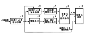
図11は、本発明による映像符号化装置の主要部を示すブロック図である。図11に示すように、本発明による映像符号化装置は、画素ビット長増加情報に基づいて入力画像の画素ビット長を増加させる画素ビット長増加手段1(一例として、図1に示す画素ビット長増加器101)と、画素ビット長増加手段1の出力データを変換する変換手段2(一例として、図1に示す変換/量子化器102)と、変換手段2の出力データをエントロピー符号化するエントロピー符号化手段3(一例として、図1に示すエントロピー符号化器103)と、入力データを非圧縮符号化する非圧縮符号化手段7(一例として、PCM符号化器107)と、エントロピー符号化手段3と非圧縮符号化手段7のいずれかの出力データを選択する多重化データ選択手段8(一例として、スイッチ121)と、画素ビット長増加情報をビットストリームに多重化する多重化手段10(一例として、多重化器110)とを備え、エントロピー符号化手段3と非圧縮符号化手段7のそれぞれの出力データに対応する画像の画素ビット長は、異なっている。
FIG. 11 is a block diagram showing a main part of a video encoding apparatus according to the present invention. As shown in FIG. 11, the video encoding apparatus according to the present invention includes a pixel bit
画素ビット長を互いに異ならせるために、一例として、画素ビット長を増加させる前の入力画像を非圧縮符号化手段7に供給させる手段を備える。そのように構成されている場合には、画素ビット長増加されていない入力画像をそのまま非圧縮符号化(例えば、PCM符号化)する。 In order to make the pixel bit lengths different from each other, for example, there is provided means for supplying the uncompressed encoding means 7 with the input image before increasing the pixel bit length. In such a configuration, an input image that has not been increased in pixel bit length is directly uncompressed (for example, PCM encoded).
図12は、本発明による他の映像符号化装置の主要部を示すブロック図である。図12に示すように、本発明による他の映像符号化装置は、図11に示す構成に加えて、画素ビット長増加情報に基づいて、画素ビット長を減少させる画素ビット長減少手段9(一例として、図6に示す画素ビット長減少器112)を備え、非圧縮符号化手段7の入力データは画素ビット長減少手段9の出力データである。
FIG. 12 is a block diagram showing a main part of another video encoding apparatus according to the present invention. As shown in FIG. 12, in addition to the configuration shown in FIG. 11, another video encoding apparatus according to the present invention includes a pixel bit length reducing means 9 (one example) for reducing the pixel bit length based on the pixel bit length increase information. 6 is provided, and the input data of the uncompressed encoding means 7 is the output data of the pixel bit
図13は、本発明による別の映像符号化装置の主要部を示すブロック図である。図13に示すように、本発明による別の映像符号化装置は、図11に示す構成に加えて、画像を予測する予測手段10(一例として、図1に示す予測器106)と、変換手段2の出力データを逆変換する逆変換手段12(一例として、図1に示す逆変換/逆量子化器104)と、非圧縮符号化手段7の出力データを復号する非圧縮復号手段13(一例として、図1に示すPCM復号器108)とを備え、非圧縮復号手段13は、少なくとも画素ビット長増加情報に基づいて、非圧縮復号した復号画像を画素ビット長増加させる。
FIG. 13 is a block diagram showing a main part of another video encoding apparatus according to the present invention. As shown in FIG. 13, in addition to the configuration shown in FIG. 11, another video encoding device according to the present invention includes a prediction unit 10 (for example, a
図14は、本発明による映像復号装置の主要部を示すブロック図である。図14に示すように、本発明による映像復号装置は、少なくとも画素ビット長増加情報を含むビットストリームを多重化解除する多重化解除手段21(一例として、図4に示す多重化解除器201)と、ビットストリームに含まれる画像の変換データをエントロピー復号するエントロピー復号手段24(一例として、図4に示すエントロピー復号器204)と、エントロピー復号した画像の変換データを逆変換する逆変換手段26(一例として、図4に示す逆変換/逆量子化器206)と、ビットストリームに含まれる画像の非圧縮符号化データを非圧縮復号する非圧縮復号手段23(一例として、図4に示すPCM復号器203)と、エントロピー復号手段24および非圧縮復号手段23を制御する復号制御手段22(一例として、図4に示す復号制御部202)とを備え、エントロピー復号手段24と非圧縮復号手段23のそれぞれの入力データに対応する画像の画素ビット長が互いに異なっている。
FIG. 14 is a block diagram showing the main part of the video decoding apparatus according to the present invention. As shown in FIG. 14, the video decoding apparatus according to the present invention includes demultiplexing means 21 (for example,
図15は、本発明による他の映像復号装置の主要部を示すブロック図である。図15に示すように、本発明による他の映像復号装置は、図14に示す構成に加えて、画像を予測する予測手段27(一例として、図4に示す予測器207)を備えている。
FIG. 15 is a block diagram showing a main part of another video decoding apparatus according to the present invention. As shown in FIG. 15, another video decoding apparatus according to the present invention includes a prediction unit 27 (an
以上に説明したように、本発明は、画素ビット長増加と非圧縮符号化に基づいた映像符号化において、エントロピー符号化と非圧縮符号化のそれぞれ出力データに対応する画像の画素ビット長を互いに異ならせる手段を提供する。そして、本発明は、イントラ予測やフレーム間予測の演算精度を画素ビット長拡張によって高めることと、ある一定の処理時間を映像符号化装置や映像復号装置に保証することとを両立しながら、画素ビット長増加分だけPCM符号化の出力データが増加する課題を解決できる。 As described above, according to the present invention, in video coding based on increase in pixel bit length and non-compression coding, pixel bit lengths of images corresponding to output data of entropy coding and non-compression coding are mutually set. Providing a different means. Then, the present invention achieves both the improvement of the calculation accuracy of intra prediction and inter-frame prediction by extending the pixel bit length and guaranteeing a certain processing time to the video encoding device and the video decoding device, The problem that the output data of PCM encoding increases by the bit length increase can be solved.
上記の実施形態の一部または全部は以下の付記のようにも記載されうるが、本発明の構成は以下の構成に限定されない。 Although part or all of the above embodiments can be described as the following supplementary notes, the configuration of the present invention is not limited to the following configurations.
(付記1)画素ビット長増加情報に基づいて入力画像の画素ビット長を増加させたデータを変換し、変換したデータをエントロピー符号化し、入力データを非圧縮符号化し、エントロピー符号化したデータと非圧縮符号化したデータのいずれかを選択し、画素ビット長増加情報をビットストリームに多重化する映像符号化方法であって、エントロピー符号化したデータと非圧縮符号化したデータのそれぞれに対応する画像の画素ビット長が互いに異なり、非圧縮符号化の入力データとして画素ビット長を増加させる前の入力画像を用いる映像符号化方法。 (Supplementary note 1) Data in which the pixel bit length of the input image is increased based on the pixel bit length increase information is converted, the converted data is entropy encoded, the input data is uncompressed, and the entropy encoded data A video encoding method that selects any one of compression-encoded data and multiplexes pixel bit length increase information into a bitstream, and is an image corresponding to each of entropy-encoded data and uncompressed-encoded data. Encoding method using an input image before the pixel bit length is increased as input data for non-compression encoding.
(付記2)画素ビット長増加情報に基づいて入力画像の画素ビット長を増加させたデータを変換し、変換したデータをエントロピー符号化し、入力データを非圧縮符号化し、エントロピー符号化したデータと非圧縮符号化したデータのいずれかを選択し、画素ビット長増加情報をビットストリームに多重化する映像符号化方法であって、エントロピー符号化したデータと非圧縮符号化したデータのそれぞれに対応する画像の画素ビット長が互いに異なり、さらに、画素ビット長を増加させたデータを対象として画素ビット長増加情報に基づいて画素ビット長を減少させ、非圧縮符号化の入力データとして、画素ビット長を減少させたデータを用いる映像符号化方法。 (Supplementary Note 2) Data obtained by increasing the pixel bit length of the input image is converted based on the pixel bit length increase information, the converted data is entropy encoded, the input data is non-compressed, and the entropy encoded data A video encoding method that selects any one of compression-encoded data and multiplexes pixel bit length increase information into a bitstream, and is an image corresponding to each of entropy-encoded data and uncompressed-encoded data. The pixel bit lengths are different from each other, and the pixel bit length is decreased based on the pixel bit length increase information for the data in which the pixel bit length is increased, and the pixel bit length is decreased as uncompressed encoded input data. Video encoding method using the processed data.
(付記3)画素ビット長増加情報に基づいて入力画像の画素ビット長を増加させたデータを変換し、変換したデータをエントロピー符号化し、入力データを非圧縮符号化し、エントロピー符号化したデータと非圧縮符号化したデータのいずれかを選択し、画素ビット長増加情報をビットストリームに多重化する映像符号化方法であって、エントロピー符号化したデータと非圧縮符号化したデータのそれぞれに対応する画像の画素ビット長が互いに異なり、さらに、変換したデータを逆変換し、非圧縮符号化したデータを復号し、復号するときに少なくとも画素ビット長増加情報に基づいて非圧縮復号した復号画像を画素ビット長増加させる映像符号化方法。 (Supplementary note 3) Data obtained by increasing the pixel bit length of the input image is converted based on the pixel bit length increase information, the converted data is entropy encoded, the input data is uncompressed encoded, and the entropy encoded data A video encoding method that selects any one of compression-encoded data and multiplexes pixel bit length increase information into a bitstream, and is an image corresponding to each of entropy-encoded data and uncompressed-encoded data. The pixel bit lengths are different from each other, the converted data is inversely transformed, the uncompressed encoded data is decoded, and the decoded image that has been uncompressed based on at least the pixel bit length increase information is decoded. Video coding method that increases the length.
(付記4)少なくとも画素ビット長増加情報を含むビットストリームを多重化解除し、ビットストリームに含まれる画像の変換データをエントロピー復号し、エントロピー復号した画像の変換データを逆変換し、ビットストリームに含まれる画像の非圧縮符号化データを非圧縮復号する映像復号方法であって、ビットストリームに含まれる画像の変換データとビットストリームに含まれる画像の非圧縮符号化データのそれぞれに対応する画像の画素ビット長が互いに異なり、非圧縮復号するときに少なくとも画素ビット長増加情報に基づいて非圧縮復号した復号画像を画素ビット長増加させる映像復号方法。 (Supplementary Note 4) Demultiplexing a bitstream including at least pixel bit length increase information, entropy decoding the conversion data of the image included in the bitstream, inversely converting the conversion data of the entropy decoded image, and including it in the bitstream Image decoding method that uncompresses and decodes uncompressed encoded data of an image to be processed, and each of image pixels corresponding to each of converted image data included in the bitstream and uncompressed encoded data of the image included in the bitstream A video decoding method in which bit lengths are different from each other, and a decoded image that has been subjected to non-compression decoding based on at least pixel bit length increase information when performing non-compression decoding increases the pixel bit length.
(付記5)少なくとも画素ビット長増加情報を含むビットストリームを多重化解除し、ビットストリームに含まれる画像の変換データをエントロピー復号し、エントロピー復号した画像の変換データを逆変換し、ビットストリームに含まれる画像の非圧縮符号化データを非圧縮復号する映像復号方法であって、ビットストリームに含まれる画像の変換データとビットストリームに含まれる画像の非圧縮符号化データのそれぞれに対応する画像の画素ビット長が互いに異なり、画像を予測する予測処理を実行する映像復号方法。 (Supplementary Note 5) Demultiplexing a bitstream including at least pixel bit length increase information, entropy decoding the image conversion data included in the bitstream, inversely converting the conversion data of the entropy decoded image, and including the bitstream in the bitstream A video decoding method for non-compressing and decoding uncompressed encoded data of an image to be processed, wherein image pixels corresponding to each of converted image data included in the bitstream and uncompressed encoded data of the image included in the bitstream A video decoding method for executing a prediction process for predicting an image with different bit lengths.
(付記6)コンピュータに、画素ビット長増加情報に基づいて入力画像の画素ビット長を増加させたデータを変換する処理と、変換したデータをエントロピー符号化する処理と、入力データを非圧縮符号化する処理と、エントロピー符号化したデータと非圧縮符号化したデータのいずれかを選択する処理と、画素ビット長増加情報をビットストリームに多重化する処理とを実行させ、エントロピー符号化したデータと非圧縮符号化したデータのそれぞれに対応する画像の画素ビット長が互いに異なり、非圧縮符号化の入力データとして画素ビット長を増加させる前の入力画像を用いる映像符号化プログラム。
(Additional remark 6) The process which converts the data which increased the pixel bit length of the input image to a computer based on pixel bit length increase information, the process which entropy-encodes the converted data, and uncompressedly encodes input data Processing, selecting either entropy encoded data or uncompressed encoded data, and processing for multiplexing pixel bit length increase information into the bitstream, and A video encoding program that uses an input image before the pixel bit length is increased as input data for non-compression encoding in which the pixel bit lengths of images corresponding to the respective compression encoded data are different from each other.
(付記7)コンピュータに、画素ビット長増加情報に基づいて入力画像の画素ビット長を増加させたデータを変換する処理と、変換したデータをエントロピー符号化する処理と、入力データを非圧縮符号化する処理と、エントロピー符号化したデータと非圧縮符号化したデータのいずれかを選択する処理と、画素ビット長増加情報をビットストリームに多重化する処理とを実行させ、エントロピー符号化したデータと非圧縮符号化したデータのそれぞれに対応する画像の画素ビット長が互いに異なり、さらに、画素ビット長を増加させたデータを対象として画素ビット長増加情報に基づいて画素ビット長を減少させる処理をコンピュータに実行させ、非圧縮符号化の入力データとして、画素ビット長を減少させたデータを用いる映像符号化プログラム。 (Supplementary note 7) Processing for converting data in which the pixel bit length of the input image is increased based on the pixel bit length increase information to the computer, processing for entropy encoding the converted data, and uncompressed encoding of the input data Processing, selecting either entropy encoded data or uncompressed encoded data, and processing for multiplexing pixel bit length increase information into the bitstream, and The processing of reducing the pixel bit length based on the pixel bit length increase information for the data with the pixel bit lengths of the images corresponding to each of the compression encoded data being different from each other and further increasing the pixel bit length is performed on the computer. Video coding program that uses data with reduced pixel bit length as input data for uncompressed coding Grams.
(付記8)コンピュータに、画素ビット長増加情報に基づいて入力画像の画素ビット長を増加させたデータを変換する処理と、変換したデータをエントロピー符号化する処理と、入力データを非圧縮符号化する処理と、エントロピー符号化したデータと非圧縮符号化したデータのいずれかを選択する処理と、画素ビット長増加情報をビットストリームに多重化する処理とを実行させ、エントロピー符号化したデータと非圧縮符号化したデータのそれぞれに対応する画像の画素ビット長が互いに異なり、さらに、コンピュータに、変換したデータを逆変換する処理と、非圧縮符号化したデータを復号する処理とを実行させ、復号するときに少なくとも画素ビット長増加情報に基づいて非圧縮復号した復号画像を画素ビット長増加させる処理をコンピュータに実行させる映像符号化プログラム。 (Supplementary Note 8) Processing for converting data in which the pixel bit length of the input image is increased based on the pixel bit length increase information to the computer, processing for entropy encoding the converted data, and uncompressed encoding of the input data Processing, selecting either entropy encoded data or uncompressed encoded data, and processing for multiplexing pixel bit length increase information into the bitstream, and The pixel bit length of the image corresponding to each of the compression encoded data is different from each other, and further, the computer executes a process of inversely converting the converted data and a process of decoding the non-compressed encoded data, and decoding A process of increasing the pixel bit length of a decoded image that has been uncompressed based on at least the pixel bit length increase information. Video encoding program to be executed by the computer.
(付記9)コンピュータに、少なくとも画素ビット長増加情報を含むビットストリームを多重化解除する処理と、ビットストリームに含まれる画像の変換データをエントロピー復号する処理と、エントロピー復号した画像の変換データを逆変換する処理と、ビットストリームに含まれる画像の非圧縮符号化データを非圧縮復号するする処理とを実行させ、ビットストリームに含まれる画像の変換データとビットストリームに含まれる画像の非圧縮符号化データのそれぞれに対応する画像の画素ビット長が互いに異なり、非圧縮復号するときに少なくとも画素ビット長増加情報に基づいて非圧縮復号した復号画像を画素ビット長増加させる処理をコンピュータに実行させる映像復号プログラム。 (Supplementary note 9) A computer demultiplexes a bitstream including at least pixel bit length increase information, entropy decodes image conversion data included in the bitstream, and reverses the entropy decoded image conversion data. A process of converting and a process of uncompressing and decoding uncompressed encoded data of the image included in the bitstream are executed, and the converted data of the image included in the bitstream and the uncompressed encoding of the image included in the bitstream are performed. Video decoding that causes the computer to execute a process for increasing the pixel bit length of a decoded image that has been uncompressed based on at least the pixel bit length increase information when performing uncompressed decoding, since the pixel bit lengths of the images corresponding to each of the data are different from each other program.
(付記10)コンピュータに、少なくとも画素ビット長増加情報を含むビットストリームを多重化解除する処理と、ビットストリームに含まれる画像の変換データをエントロピー復号する処理と、エントロピー復号した画像の変換データを逆変換する処理と、ビットストリームに含まれる画像の非圧縮符号化データを非圧縮復号するする処理とを実行させ、ビットストリームに含まれる画像の変換データとビットストリームに含まれる画像の非圧縮符号化データのそれぞれに対応する画像の画素ビット長が互いに異なり、画像を予測する予測処理をコンピュータに実行させる映像復号プログラム。 (Supplementary Note 10) A computer de-multiplexes a bit stream including at least pixel bit length increase information, entropy-decodes image conversion data included in the bit stream, and reverses the entropy-decoded image conversion data. A process of converting and a process of uncompressing and decoding uncompressed encoded data of the image included in the bitstream are executed, and the converted data of the image included in the bitstream and the uncompressed encoding of the image included in the bitstream are performed. A video decoding program for causing a computer to execute a prediction process in which pixel bit lengths of images corresponding to each of data are different from each other and predict an image.
以上、実施形態および実施例を参照して本願発明を説明したが、本願発明は上記実施形態および実施例に限定されるものではない。本願発明の構成や詳細には、本願発明のスコープ内で当業者が理解し得る様々な変更をすることができる。 While the present invention has been described with reference to the embodiments and examples, the present invention is not limited to the above embodiments and examples. Various changes that can be understood by those skilled in the art can be made to the configuration and details of the present invention within the scope of the present invention.
この出願は、2010年7月13日に出願された日本特許出願2010−159059および2011年2月25日に出願された日本特許出願2011−040530を基礎とする優先権を主張し、その開示の全てをここに取り込む。 This application claims priority based on Japanese Patent Application No. 2010-159059 filed on July 13, 2010 and Japanese Patent Application No. 2011-040530 filed on February 25, 2011. Get everything here.
1 画素ビット長増加手段
2 変換手段
3 エントロピー符号化手段
7 非圧縮符号化手段
8 多重化データ選択手段
9 画素ビット長減少手段
10 多重化手段
11 予測手段
12 逆変換手段
13 非圧縮復号手段
21 多重化解除手段
22 復号制御手段
23 非圧縮復号手段
24 エントロピー復号手段
26 逆変換手段
27 予測手段
101 画素ビット長増加器
102 変換/量子化器
103 エントロピー符号化器
104 逆変換/逆量子化器
105 バッファ
106 予測器
107 PCM符号化器
108 PCM復号器
109 多重化データ選択器
110 多重化器
111 画素ビット長増加器
112 画素ビット長減少器
121 スイッチ
122 スイッチ
201 多重化解除器
202 復号制御部
203 PCM復号器
204 エントロピー復号器
205 画素ビット長増加器
206 逆変換/逆量子化器
207 予測器
208 バッファ
209 画素ビット長減少器
221 スイッチ
222 スイッチ
1001 プロセッサ
1002 プログラムメモリ
1003 記憶媒体
1004 記憶媒体
DESCRIPTION OF
Claims (3)
前記ビットストリームに含まれる画像の非圧縮符号化データを非圧縮復号する非圧縮復号手段と、
前記非圧縮復号したデータの画素ビット長を増加させる画素ビット長増加手段と、
前記エントロピー復号手段および前記非圧縮復号手段を制御する復号制御手段とを備え、
前記画素ビット長増加手段は、前記非圧縮復号手段の入力データに対応する画像の画素ビット長を、前記エントロピー復号手段の入力データに対応する画像の画素ビット長に揃える
ことを特徴とする映像復号装置。 Entropy decoding means for entropy decoding the conversion data of the image included in the bitstream;
Uncompressed decoding means for performing uncompressed decoding of uncompressed encoded data of an image included in the bitstream;
Pixel bit length increasing means for increasing the pixel bit length of the uncompressed decoded data;
Decoding control means for controlling the entropy decoding means and the uncompressed decoding means,
The video bit length increasing means aligns the pixel bit length of the image corresponding to the input data of the uncompressed decoding means with the pixel bit length of the image corresponding to the input data of the entropy decoding means. apparatus.
前記ビットストリームに含まれる画像の非圧縮符号化データを非圧縮復号し、
前記エントロピー復号と前記非圧縮復号とを制御し、
前記非圧縮復号の入力データに対応する画像の画素ビット長が、前記エントロピー復号の入力データに対応する画像の画素ビット長と揃うように、前記非圧縮復号の入力データに対応する画像の画素ビット長を増加させる
ことを特徴とする映像復号方法。 Entropy-decode the converted image data included in the bitstream,
Uncompressed and decoded uncompressed encoded data of an image included in the bitstream;
Controlling the entropy decoding and the uncompressed decoding;
The pixel bits of the image corresponding to the input data of the uncompressed decoding so that the pixel bit length of the image corresponding to the input data of the uncompressed decoding is aligned with the pixel bit length of the image corresponding to the input data of the entropy decoding A video decoding method characterized by increasing the length.
ビットストリームに含まれる画像の変換データをエントロピー復号する処理と、
前記ビットストリームに含まれる画像の非圧縮符号化データを非圧縮復号する処理と、
前記エントロピー復号と前記非圧縮復号とを制御する処理と、
前記非圧縮復号の入力データに対応する画像の画素ビット長が、前記エントロピー復号の入力データに対応する画像の画素ビット長と揃うように、前記非圧縮復号の入力データに対応する画像の画素ビット長を増加させる処理と
を実行させるための映像復号プログラム。 On the computer,
A process for entropy decoding the converted image data included in the bitstream;
A process of uncompressing and decoding uncompressed encoded data of an image included in the bitstream;
A process for controlling the entropy decoding and the uncompressed decoding;
The pixel bits of the image corresponding to the input data of the uncompressed decoding so that the pixel bit length of the image corresponding to the input data of the uncompressed decoding is aligned with the pixel bit length of the image corresponding to the input data of the entropy decoding Video decoding program for executing the process of increasing the length.
Priority Applications (1)
| Application Number | Priority Date | Filing Date | Title |
|---|---|---|---|
| JP2015204722A JP5861800B2 (en) | 2010-07-13 | 2015-10-16 | Video decoding apparatus, video decoding method, and program |
Applications Claiming Priority (5)
| Application Number | Priority Date | Filing Date | Title |
|---|---|---|---|
| JP2010159059 | 2010-07-13 | ||
| JP2010159059 | 2010-07-13 | ||
| JP2011040530 | 2011-02-25 | ||
| JP2011040530 | 2011-02-25 | ||
| JP2015204722A JP5861800B2 (en) | 2010-07-13 | 2015-10-16 | Video decoding apparatus, video decoding method, and program |
Related Parent Applications (1)
| Application Number | Title | Priority Date | Filing Date |
|---|---|---|---|
| JP2014167125A Division JP5861752B2 (en) | 2010-07-13 | 2014-08-20 | Video decoding apparatus, video decoding method, and program |
Related Child Applications (1)
| Application Number | Title | Priority Date | Filing Date |
|---|---|---|---|
| JP2015248433A Division JP6065095B2 (en) | 2010-07-13 | 2015-12-21 | Video encoding apparatus, video decoding apparatus, video encoding method, video decoding method, and program |
Publications (2)
| Publication Number | Publication Date |
|---|---|
| JP2016007085A true JP2016007085A (en) | 2016-01-14 |
| JP5861800B2 JP5861800B2 (en) | 2016-02-16 |
Family
ID=45469148
Family Applications (5)
| Application Number | Title | Priority Date | Filing Date |
|---|---|---|---|
| JP2012524445A Active JP5807638B2 (en) | 2010-07-13 | 2011-07-08 | Video encoding apparatus, video decoding apparatus, video encoding method, video decoding method, and program |
| JP2014167125A Active JP5861752B2 (en) | 2010-07-13 | 2014-08-20 | Video decoding apparatus, video decoding method, and program |
| JP2015204722A Active JP5861800B2 (en) | 2010-07-13 | 2015-10-16 | Video decoding apparatus, video decoding method, and program |
| JP2015248433A Active JP6065095B2 (en) | 2010-07-13 | 2015-12-21 | Video encoding apparatus, video decoding apparatus, video encoding method, video decoding method, and program |
| JP2016245080A Active JP6274299B2 (en) | 2010-07-13 | 2016-12-19 | Video decoding apparatus and video decoding method |
Family Applications Before (2)
| Application Number | Title | Priority Date | Filing Date |
|---|---|---|---|
| JP2012524445A Active JP5807638B2 (en) | 2010-07-13 | 2011-07-08 | Video encoding apparatus, video decoding apparatus, video encoding method, video decoding method, and program |
| JP2014167125A Active JP5861752B2 (en) | 2010-07-13 | 2014-08-20 | Video decoding apparatus, video decoding method, and program |
Family Applications After (2)
| Application Number | Title | Priority Date | Filing Date |
|---|---|---|---|
| JP2015248433A Active JP6065095B2 (en) | 2010-07-13 | 2015-12-21 | Video encoding apparatus, video decoding apparatus, video encoding method, video decoding method, and program |
| JP2016245080A Active JP6274299B2 (en) | 2010-07-13 | 2016-12-19 | Video decoding apparatus and video decoding method |
Country Status (9)
| Country | Link |
|---|---|
| US (5) | US9210427B2 (en) |
| EP (2) | EP2595379B1 (en) |
| JP (5) | JP5807638B2 (en) |
| KR (3) | KR101513507B1 (en) |
| CN (6) | CN105847812B (en) |
| BR (5) | BR122022001404B1 (en) |
| HK (4) | HK1182563A1 (en) |
| PL (1) | PL2595379T3 (en) |
| WO (1) | WO2012008130A1 (en) |
Families Citing this family (22)
| Publication number | Priority date | Publication date | Assignee | Title |
|---|---|---|---|---|
| EP2595379B1 (en) | 2010-07-13 | 2020-10-21 | Nec Corporation | Video decoder, video decoding method, and video decoding program |
| JP5850214B2 (en) | 2011-01-11 | 2016-02-03 | ソニー株式会社 | Image processing apparatus and method, program, and recording medium |
| WO2012114725A1 (en) | 2011-02-22 | 2012-08-30 | パナソニック株式会社 | Image encoding method, image decoding method, image encoding device, image decoding device, and image encoding/decoding device |
| CN102907097B (en) * | 2011-02-22 | 2016-01-20 | 太格文-Ii有限责任公司 | Filtering method, moving picture encoding device, dynamic image decoding device and moving picture encoding decoding device |
| UA109312C2 (en) | 2011-03-04 | 2015-08-10 | PULSE-CODE MODULATION WITH QUANTITATION FOR CODING VIDEO INFORMATION | |
| EP2736253B1 (en) | 2011-07-19 | 2020-03-11 | Tagivan Ii Llc | Filtering method, moving image decoding method, moving image encoding method, moving image decoding apparatus, moving image encoding apparatus, and moving image encoding/decoding apparatus |
| WO2013064548A2 (en) * | 2011-11-03 | 2013-05-10 | Panasonic Corporation | Quantization parameter for blocks coded in the pcm mode |
| CN107743231B (en) * | 2012-06-25 | 2020-10-16 | 日本电气株式会社 | Video decoding apparatus and video decoding method |
| US9978156B2 (en) * | 2012-10-03 | 2018-05-22 | Avago Technologies General Ip (Singapore) Pte. Ltd. | High-throughput image and video compression |
| US9501864B2 (en) * | 2013-12-27 | 2016-11-22 | Intel Corporation | Adaptive depth offset compression |
| US9571468B2 (en) * | 2014-01-05 | 2017-02-14 | Whovoo, Inc. | Encoding data using a variable number of pixels and bits based on entropy |
| JP5850272B2 (en) * | 2014-01-10 | 2016-02-03 | ソニー株式会社 | Image processing apparatus and method, program, and recording medium |
| JP6653860B2 (en) * | 2014-05-26 | 2020-02-26 | シャープ株式会社 | Image decoding device, image encoding device, image decoding method, image encoding method, and computer-readable recording medium |
| EP2958329B1 (en) | 2014-06-16 | 2018-12-05 | Thomson Licensing | Method for encoding and decoding an image block based on dynamic range extension, encoder and decoder |
| KR101638154B1 (en) | 2014-07-29 | 2016-07-12 | 주식회사 더즈텍 | Apparatus of receiving data with reference clock and method thereof |
| KR101654767B1 (en) | 2015-05-29 | 2016-09-07 | 주식회사 더즈텍 | Phase Locked Loop with reference clock, clock data recovery circuit, and apparatus of receiving data |
| JP6115620B2 (en) * | 2015-11-25 | 2017-04-19 | ソニー株式会社 | Image processing apparatus and method, program, and recording medium |
| JP6115619B2 (en) * | 2015-11-25 | 2017-04-19 | ソニー株式会社 | Image processing apparatus and method, program, and recording medium |
| CN110114803B (en) * | 2016-12-28 | 2023-06-27 | 松下电器(美国)知识产权公司 | Three-dimensional model distribution method, three-dimensional model reception method, three-dimensional model distribution device, and three-dimensional model reception device |
| JP6299901B2 (en) * | 2017-03-03 | 2018-03-28 | ソニー株式会社 | Image processing apparatus and method, program, and recording medium |
| JP6332502B2 (en) * | 2017-03-03 | 2018-05-30 | ソニー株式会社 | Image processing apparatus and method, program, and recording medium |
| DE102018122297A1 (en) * | 2018-09-12 | 2020-03-12 | Arnold & Richter Cine Technik Gmbh & Co. Betriebs Kg | Process for compression and decompression of image data |
Family Cites Families (23)
| Publication number | Priority date | Publication date | Assignee | Title |
|---|---|---|---|---|
| US4861335A (en) | 1985-07-26 | 1989-08-29 | Duoject Medical Systems Inc. | Syringe |
| JP4214440B2 (en) * | 2000-10-19 | 2009-01-28 | ソニー株式会社 | Data processing apparatus, data processing method, and recording medium |
| JP4240283B2 (en) | 2002-10-10 | 2009-03-18 | ソニー株式会社 | Decoding device and decoding method |
| US20060126744A1 (en) * | 2004-12-10 | 2006-06-15 | Liang Peng | Two pass architecture for H.264 CABAC decoding process |
| JP4440863B2 (en) * | 2005-09-13 | 2010-03-24 | パナソニック株式会社 | Encoding / decoding device, encoding / decoding method, encoding / decoding integrated circuit, and encoding / decoding program |
| CN100466741C (en) * | 2005-11-11 | 2009-03-04 | 北京微视讯通数字技术有限公司 | A method and device for carrying out coding using correlation between video signal frames in video code processing |
| US20070122045A1 (en) * | 2005-11-29 | 2007-05-31 | Jiun-Yuan Wu | System for scaling a picture unit from a first video resolution format to a second video resolution format |
| JP4384130B2 (en) | 2006-03-28 | 2009-12-16 | 株式会社東芝 | Video decoding method and apparatus |
| WO2007116551A1 (en) * | 2006-03-30 | 2007-10-18 | Kabushiki Kaisha Toshiba | Image coding apparatus and image coding method, and image decoding apparatus and image decoding method |
| JP2008022383A (en) | 2006-07-13 | 2008-01-31 | Matsushita Electric Ind Co Ltd | Image encoding apparatus |
| EP3484154A1 (en) * | 2006-10-25 | 2019-05-15 | GE Video Compression, LLC | Quality scalable coding |
| KR100837410B1 (en) * | 2006-11-30 | 2008-06-12 | 삼성전자주식회사 | Method and apparatus for visually lossless image data compression |
| US8107751B2 (en) * | 2007-03-16 | 2012-01-31 | Sharp Laboratories Of America, Inc. | DPCM with adaptive range and PCM escape mode |
| JP4829836B2 (en) | 2007-04-26 | 2011-12-07 | キヤノン株式会社 | Image encoding apparatus, control method for image encoding apparatus, computer program, decoding apparatus, and computer-readable storage medium |
| JP4983415B2 (en) * | 2007-06-11 | 2012-07-25 | ソニー株式会社 | Image signal processing apparatus, image signal processing method, and program |
| US9521433B2 (en) | 2007-09-06 | 2016-12-13 | Nec Corporation | Video encoding device, video decoding device, video encoding method, video decoding method, video encoding or decoding program |
| EP2051527A1 (en) * | 2007-10-15 | 2009-04-22 | Thomson Licensing | Enhancement layer residual prediction for bit depth scalability using hierarchical LUTs |
| JP5697301B2 (en) | 2008-10-01 | 2015-04-08 | 株式会社Nttドコモ | Moving picture encoding apparatus, moving picture decoding apparatus, moving picture encoding method, moving picture decoding method, moving picture encoding program, moving picture decoding program, and moving picture encoding / decoding system |
| JP2010159059A (en) | 2009-01-06 | 2010-07-22 | Asahi Kogyo Kk | Packaging container |
| JP5408655B2 (en) | 2009-08-10 | 2014-02-05 | 米沢ダイヤエレクトロニクス株式会社 | Printed wiring board and manufacturing method thereof |
| EP2595379B1 (en) * | 2010-07-13 | 2020-10-21 | Nec Corporation | Video decoder, video decoding method, and video decoding program |
| US20120087411A1 (en) | 2010-10-12 | 2012-04-12 | Apple Inc. | Internal bit depth increase in deblocking filters and ordered dither |
| US8923389B1 (en) * | 2011-01-13 | 2014-12-30 | Zenverge, Inc. | Unified scaling with differential coding for internal bit depth extension and reference frame compression |
-
2011
- 2011-07-08 EP EP11806465.8A patent/EP2595379B1/en active Active
- 2011-07-08 KR KR1020147008017A patent/KR101513507B1/en active IP Right Grant
- 2011-07-08 US US13/695,461 patent/US9210427B2/en active Active
- 2011-07-08 BR BR122022001404-6A patent/BR122022001404B1/en active IP Right Grant
- 2011-07-08 CN CN201610312083.7A patent/CN105847812B/en active Active
- 2011-07-08 PL PL11806465T patent/PL2595379T3/en unknown
- 2011-07-08 WO PCT/JP2011/003927 patent/WO2012008130A1/en active Application Filing
- 2011-07-08 CN CN201610031867.2A patent/CN105491382B/en active Active
- 2011-07-08 EP EP20194967.4A patent/EP3787286A1/en active Pending
- 2011-07-08 JP JP2012524445A patent/JP5807638B2/en active Active
- 2011-07-08 BR BR112013000579-3A patent/BR112013000579B1/en active IP Right Grant
- 2011-07-08 CN CN201610032630.6A patent/CN105430405B/en active Active
- 2011-07-08 BR BR122022001405-4A patent/BR122022001405B1/en active IP Right Grant
- 2011-07-08 KR KR1020127029824A patent/KR101435095B1/en active IP Right Grant
- 2011-07-08 CN CN201610311767.5A patent/CN105828078B/en active Active
- 2011-07-08 CN CN201610312361.9A patent/CN105847813B/en active Active
- 2011-07-08 BR BR122020015661-9A patent/BR122020015661B1/en active IP Right Grant
- 2011-07-08 CN CN201180034498.8A patent/CN103004191B/en active Active
- 2011-07-08 BR BR122020015660-0A patent/BR122020015660B1/en active IP Right Grant
- 2011-07-08 KR KR1020147024227A patent/KR101538362B1/en active IP Right Grant
-
2013
- 2013-08-19 HK HK13109649.1A patent/HK1182563A1/en unknown
- 2013-08-19 HK HK16112479.7A patent/HK1224471A1/en unknown
- 2013-08-19 HK HK16108790.7A patent/HK1220842A1/en unknown
- 2013-08-19 HK HK16108785.4A patent/HK1220841A1/en unknown
-
2014
- 2014-08-20 JP JP2014167125A patent/JP5861752B2/en active Active
-
2015
- 2015-10-16 JP JP2015204722A patent/JP5861800B2/en active Active
- 2015-11-03 US US14/931,271 patent/US9510011B2/en active Active
- 2015-11-03 US US14/931,305 patent/US9936212B2/en active Active
- 2015-11-03 US US14/931,181 patent/US9532073B2/en active Active
- 2015-12-21 JP JP2015248433A patent/JP6065095B2/en active Active
-
2016
- 2016-11-07 US US15/344,635 patent/US10097847B2/en active Active
- 2016-12-19 JP JP2016245080A patent/JP6274299B2/en active Active
Also Published As
Similar Documents
| Publication | Publication Date | Title |
|---|---|---|
| JP6274299B2 (en) | Video decoding apparatus and video decoding method | |
| JP7271683B2 (en) | Encoders, decoders and corresponding intra-prediction methods | |
| JP4991699B2 (en) | Scalable encoding and decoding methods for video signals | |
| WO2012070232A1 (en) | Image encoding device, image decoding device, image encoding method, image decoding method, and program | |
| JP7366149B2 (en) | An encoder, decoder, and corresponding method for harmonizing matrix-based intra-prediction and quadratic transform core selection | |
| KR20160070771A (en) | Features of base color index map mode for video and image coding and decoding | |
| JP2022513457A (en) | Methods and equipment for color conversion in VVC | |
| JP2022517081A (en) | Deblocking filter for subpartition boundaries caused by intra-subpartition coding tools | |
| JP7357736B2 (en) | Encoding device, decoding device, and program | |
| KR20140081681A (en) | Video encoding method and apparatus using the same | |
| JP7322178B2 (en) | Method, apparatus and computer program for indication of sublayer number in multi-layered video stream | |
| JP2023515189A (en) | Decoder and corresponding method for signaling picture partition information for slices | |
| JP7366216B2 (en) | Encoding device, decoding device, and program | |
| WO2022044267A1 (en) | Video encoding device, video decoding device, video encoding method, and video decoding method | |
| WO2021201222A1 (en) | Encoding device, decoding device, and program |
Legal Events
| Date | Code | Title | Description |
|---|---|---|---|
| A621 | Written request for application examination |
Free format text: JAPANESE INTERMEDIATE CODE: A621 Effective date: 20151016 |
|
| A871 | Explanation of circumstances concerning accelerated examination |
Free format text: JAPANESE INTERMEDIATE CODE: A871 Effective date: 20151016 |
|
| TRDD | Decision of grant or rejection written | ||
| A975 | Report on accelerated examination |
Free format text: JAPANESE INTERMEDIATE CODE: A971005 Effective date: 20151118 |
|
| A01 | Written decision to grant a patent or to grant a registration (utility model) |
Free format text: JAPANESE INTERMEDIATE CODE: A01 Effective date: 20151124 |
|
| A61 | First payment of annual fees (during grant procedure) |
Free format text: JAPANESE INTERMEDIATE CODE: A61 Effective date: 20151207 |
|
| R150 | Certificate of patent or registration of utility model |
Ref document number: 5861800 Country of ref document: JP Free format text: JAPANESE INTERMEDIATE CODE: R150 |