JP4983415B2 - Image signal processing apparatus, image signal processing method, and program - Google Patents
Image signal processing apparatus, image signal processing method, and program Download PDFInfo
- Publication number
- JP4983415B2 JP4983415B2 JP2007154191A JP2007154191A JP4983415B2 JP 4983415 B2 JP4983415 B2 JP 4983415B2 JP 2007154191 A JP2007154191 A JP 2007154191A JP 2007154191 A JP2007154191 A JP 2007154191A JP 4983415 B2 JP4983415 B2 JP 4983415B2
- Authority
- JP
- Japan
- Prior art keywords
- image signal
- diff
- signal
- gain
- amplitude
- Prior art date
- Legal status (The legal status is an assumption and is not a legal conclusion. Google has not performed a legal analysis and makes no representation as to the accuracy of the status listed.)
- Expired - Fee Related
Links
Images


Classifications
-
- H—ELECTRICITY
- H04—ELECTRIC COMMUNICATION TECHNIQUE
- H04N—PICTORIAL COMMUNICATION, e.g. TELEVISION
- H04N19/00—Methods or arrangements for coding, decoding, compressing or decompressing digital video signals
- H04N19/85—Methods or arrangements for coding, decoding, compressing or decompressing digital video signals using pre-processing or post-processing specially adapted for video compression
- H04N19/86—Methods or arrangements for coding, decoding, compressing or decompressing digital video signals using pre-processing or post-processing specially adapted for video compression involving reduction of coding artifacts, e.g. of blockiness
-
- H—ELECTRICITY
- H04—ELECTRIC COMMUNICATION TECHNIQUE
- H04N—PICTORIAL COMMUNICATION, e.g. TELEVISION
- H04N19/00—Methods or arrangements for coding, decoding, compressing or decompressing digital video signals
- H04N19/44—Decoders specially adapted therefor, e.g. video decoders which are asymmetric with respect to the encoder
-
- H—ELECTRICITY
- H04—ELECTRIC COMMUNICATION TECHNIQUE
- H04N—PICTORIAL COMMUNICATION, e.g. TELEVISION
- H04N19/00—Methods or arrangements for coding, decoding, compressing or decompressing digital video signals
- H04N19/80—Details of filtering operations specially adapted for video compression, e.g. for pixel interpolation
Landscapes
- Engineering & Computer Science (AREA)
- Multimedia (AREA)
- Signal Processing (AREA)
- Picture Signal Circuits (AREA)
- Image Processing (AREA)
Description
本発明は、例えば映像信号を記録する記録再生装置に適用して好適な画像信号処理装置、画像信号処理方法、並びにプログラムに関する。 The present invention relates to an image signal processing apparatus, an image signal processing method, and a program suitable for application to, for example, a recording / reproducing apparatus for recording a video signal.
従来、ベースバンドビデオ信号に対して行われるデジタル信号処理では、8ビットの量子化ビット数で量子化されたデジタル信号が用いられることが多い。このため、多くの映像コンテンツは8ビットで製作・記録されており、映像コンテンツを表示するディスプレイも、8ビットに対応したものが主流である。 Conventionally, digital signal processing performed on a baseband video signal often uses a digital signal quantized with an 8-bit quantization bit number. For this reason, many video contents are produced and recorded in 8 bits, and displays that display video contents are mainly compatible with 8 bits.
ところが、8ビットで量子化されたデジタル信号が映像としてディスプレイに表示される場合、輝度値が緩やかに変化すべき箇所において、疑似輪郭と呼ばれる等高線状の縞が発生してしまうという問題があった。輝度値が緩やかに変化する箇所では、8ビットでは量子化の幅が粗いケースがあり、このような場合には、緩やかな輝度変化が階段状に変化してしまうためである。 However, when a digital signal quantized with 8 bits is displayed on a display as a video image, there is a problem that contour stripes called pseudo contours are generated at locations where the luminance value should change slowly. . This is because, in a portion where the luminance value changes gradually, there are cases in which the width of quantization is coarse in 8 bits, and in such a case, a gradual change in luminance changes in a stepwise manner.
このような画像劣化を防ぐため、8ビットで量子化されたデジタル信号のビット数を、10ビットや12ビット等に増加させて、量子化精度以下の信号を再生する手法が知られている。 In order to prevent such image degradation, a technique is known in which the number of bits of a digital signal quantized with 8 bits is increased to 10 bits, 12 bits, etc., and a signal with a quantization accuracy or lower is reproduced.
特許文献1には、入力されたデジタル信号より多いビット数のデジタル信号を生成することについての開示がある。
ところで、入力されたデジタル信号より多いビット数のデジタル信号を生成する手法としては、ローパスフィルタ(以下、LPFとも称する)が知られている。ところが、量子化されたデジタルの画像信号をローパスフィルタにかけると、高域周波数成分が削除されてしまうため、ディスプレイ等に表示される画像がぼけてしまうという問題があった。 Incidentally, a low-pass filter (hereinafter also referred to as LPF) is known as a technique for generating a digital signal having a larger number of bits than the input digital signal. However, when a quantized digital image signal is applied to a low-pass filter, a high frequency component is deleted, and there is a problem that an image displayed on a display or the like is blurred.
本発明はかかる点に鑑みてなされたものであり、量子化ビット数の不足による擬似輪郭現象を、画像をぼけさせることなく改善することを目的とする。 The present invention has been made in view of the above point, and an object thereof is to improve a pseudo contour phenomenon caused by an insufficient number of quantization bits without blurring an image.
本発明は、入力されたデジタル画像信号を構成する各画素のうちの、注目画素と前記注目画素の周囲の画素で構成される領域における階調の変化度合いに応じて、擬似輪郭が目立つ画像か否かを判定する擬似輪郭判定部と、入力されたデジタル画像信号のビット数を伸張して高域周波数帯の画像信号を通過させる帯域通過フィルタと、帯域通過フィルタを通過した画像信号の振幅を所定のレベルに制限する振幅制限処理部と、振幅制限処理部で振幅制限された画像信号のゲインの値を、擬似輪郭判定部の判定結果に応じて切り替えるゲイン調整部と、入力されたデジタル画像信号から、ゲイン調整部から出力された画像信号を減算する加算器とを備えるようにしたものである。 The present invention is an image in which a pseudo contour is conspicuous according to the degree of change in gradation in a region composed of a pixel of interest and pixels around the pixel of interest among the pixels constituting the input digital image signal. A pseudo contour determination unit that determines whether or not, a band pass filter that extends the number of bits of the input digital image signal and passes the image signal in the high frequency band, and the amplitude of the image signal that has passed through the band pass filter digital gain value of the amplitude-limited image signal, and a gain adjuster Ru switched according to the pseudo contour determination of the determination result, which is input by the amplitude limit unit for limiting to a predetermined level, the amplitude limitation process section And an adder for subtracting the image signal output from the gain adjusting unit from the image signal.
このようにしたことで、加算器から出力される信号は、入力画像信号のうち、微小振幅信号にのみローパスフィルタ処理を行った場合と等価の周波数特性を有するようになる。 By doing so, the signal output from the adder has a frequency characteristic equivalent to the case where the low-pass filter processing is performed only on the minute amplitude signal of the input image signal.
本発明によると、微小振幅信号にのみローパスフィルタ処理が施されるようになるので、画像全体をボケさせることなく、擬似輪郭の改善を図ることができるようになる。 According to the present invention, since the low pass filter process is performed only on the minute amplitude signal, the pseudo contour can be improved without blurring the entire image.
以下、本発明の一実施の形態を、添付図面を参照して説明する。本実施の形態においては、画像信号処理装置として、入力端子やチューナ等から入力された映像信号を記録又は再生する記録再生装置に適用した場合を例に挙げて説明する。 Hereinafter, an embodiment of the present invention will be described with reference to the accompanying drawings. In the present embodiment, the case where the present invention is applied to a recording / reproducing apparatus that records or reproduces a video signal input from an input terminal, a tuner, or the like will be described as an example.
図2は、記録再生装置100の内部構成例を示すブロック図である。まず、記録系の構成から説明を行う。図2に示す記録再生装置100は、ライン入力端子1、アナログチューナ2、セレクタ3、ビデオデコーダ4、ビデオ・グラフィック・プロセッサ30、セレクタ5、MPEG(Moving Picture Experts Group)エンコーダ6、ストリームプロセッサ50、ディスクドライブ10、ハードディスクドライブ11、HDMI(High Definition Multimedia Interface)端子12、HDV(High-Definition Video)プロセッサ13、デジタルチューナ14とを備える。
FIG. 2 is a block diagram showing an example of the internal configuration of the recording / reproducing
セレクタ3は、ライン入力端子1から入力される映像信号と、アナログチューナ2から入力される映像信号のうちいずれかを、ユーザによる選択操作等に基づいて選択し、その後段に接続されたビデオデコーダ4に出力する。ビデオデコーダ4は、入力されたNTSC(National Television Standards Committee)方式等のアナログ映像信号を、8ビットのデジタル映像信号に変換して輝度信号とクロマ信号とに分離すると共に、デコード処理を施してベースバンド信号を得る。そして、得たベースバンド信号をセレクタ5及びビデオ・グラフィック・プロセッサ30に出力する。ビデオデコーダ4におけるサンプリングレートは、例えば4:4:4であるものとする。
The
ビデオ・グラフィック・プロセッサ30は、入力された映像信号に対してスケーリング処理や、画質調整処理・ノイズリダクション処理等の様々なビデオ信号処理を行う。そして、ビデオ信号処理された映像信号にグラフィックス信号等を合成し、セレクタ5に出力する。ビデオ・グラフィック・プロセッサ30では、擬似輪郭の改善処理も行うようにしてあり、詳細については後述する。
The video
セレクタ5は、ビデオデコーダ4から入力される映像信号と、ビデオ・グラフィック・プロセッサ30から入力される映像信号のうちいずれかを、ユーザによる選択操作等に基づいて選択し、その後段に接続されたMPEGエンコーダ6に出力する。MPEGエンコーダ6は、入力された映像信号を、MPEG1、MPEG2、MPEG4、MPEG4−AVC/H.264等の方式でエンコードし、エンコードされたストリームをストリームプロセッサ50に出力する。ストリームプロセッサ50は、記録媒体に所望のストリーム形態への変換や多重化の処理等を行い、処理されたストリームをディスクドライブ10やハードディスクドライブ11に出力する。
The selector 5 selects one of the video signal input from the
ストリームプロセッサ50には、HDVプロセッサ13とデジタルチューナ14も接続されており、HDVプロセッサ13には、IEEE1394端子12が接続されている。ストリームプロセッサ50は、IEEE1394端子12とHDVプロセッサ13を介して入力されたストリームと、デジタルチューナ14から入力されたストリームに対して、もユーザからの操作入力等により選択されたビデオストリームを、入力されたストリームから抜き出す処理や、パーズ処理等を行い、処理されたストリームをディスクドライブ10やハードディスクドライブ11に出力する。
An
ディスクドライブ10は、ディスクドライブ10に接続されたBD(Blu-Ray Disk:登録商標)やDVD(Digital Versatile Disc)等のメディアに対する、ストリームの書き込み又は読み出し処理を行う。ハードディスクドライブ11は、ハードディスクドライブ11に接続されたハードディスクに対する、ストリームの書き込み又は読み出し処理を行う。
The
上述のように構成される記録再生装置100において、ライン入力端子1から入力された映像信号又はアナログチューナ2から入力された映像信号が、ディスクドライブ10やハードディスクドライブ11に接続された媒体に記録される場合には、セレクタ3により選択されたいずれかの映像信号が、ビデオデコーダ4に出力される。ビデオデコーダ4に入力された映像信号は、スケーリング処理やビデオ信号処理が施され、ビデオ・グラフィック・プロセッサ30及びセレクタ5に出力される。そして、ビデオデコーダ4からの出力映像信号とビデオ・グラフィック・プロセッサ30のいずれかが、セレクタ5によって選択され、MPEGエンコーダ6に出力される。
In the recording / reproducing
MPEGエンコーダ6に入力された映像信号は、所定のMPEG方式でエンコードされて、ストリームとしてストリームプロセッサ50に出力される。ストリームプロセッサ50に入力されたストリームは、多重化等の処理が施された上で、ディスクドライブ10やハードディスクドライブ11に接続された媒体に出力され、記録される。
The video signal input to the
IEEE1394端子12から入力されたストリームは、HDVプロセッサ13を経てストリームプロセッサ50に入力され、デジタルチューナ12から入力されたストリームも、ストリームプロセッサ50に入力される。ストリームプロセッサ50に入力されたストリームは、ユーザからの操作入力等に基づいて取捨選択され、パーズ処理等が行われた上で、ディスクドライブ10やハードディスクドライブ11に接続された媒体に出力され、記録される。また、ストリームプロセッサ50に入力されたストリームは、ユーザからの操作入力等に基づく取捨選択や、パーズ処理等が行われた後で、MPEGデコーダ15aと15bに出力される。
The stream input from the IEEE 1394
MPEGデコーダ15aと15bに入力されたストリームは、MPEGデコーダ15aと15bデコードされた後、ビデオ・グラフィック・プロセッサ30及びセレクタ5を経由して、MPEGエンコーダ6に出力される。MPEGエンコーダ6に入力されたストリームは、所望のMPEG方式にエンコードされ、再びストリームプロセッサ50に出力される。そして、ストリームプロセッサ50に入力されたストリームは、ディスクドライブ10やハードディスクドライブ11に接続された媒体に出力され、記録される。
The streams input to the
次に、同じく図2を参照して、再生系及び表示系の構成について説明する。図2に示した記録再生装置100は、上述した構成に加えて、MPEGデコーダ15a及び15b、HDMIトランスミッタ16(以下、HDMI Tx16と称する)、HDMIコネクタ17、デジタル・アナログコンバータ18(以下、DAC18と称する)、コンポーネント端子19、コンポジットビデオ端子20とを備える。
Next, the configuration of the reproduction system and the display system will be described with reference to FIG. In addition to the configuration described above, the recording / reproducing
MPEGデコーダ15a及び15bは、ストリームプロセッサ50から出力されたストリームにデコード処理を施してベースバンド信号を得て、得られたベースバンド信号をビデオ・グラフィック・プロセッサ30に出力する。HDMI Tx16は、入力されたベースバンド信号をTMDS(Transition Minimized Differential Signaling)信号に変換して、HDMIコネクタ17に出力する。
The
DAC18は、ビデオ・グラフィック・プロセッサ30から出力されたデジタルのベースバンド信号を、アナログのベースバンド信号に変換する。また、ビデオ・グラフィック・プロセッサ30からNTSC等に変換して出力されたデジタルのビデオエンコード信号を、アナログのビデオ信号に変換する。DAC18には、信号の出力先としてコンポーネント端子19とコンポジットビデオ端子20が接続されている。なお、コンポジットビデオ端子20の代わりにS端子を用いる構成としてもよい。
The
上述のように構成される記録再生装置100において、ライン入力端子1から入力された映像信号又はアナログチューナ2から入力された映像信号が、HDMIコネクタ17やコンポーネント端子19、コンポジットビデオ端子20を介して接続された外部の表示機器に表示される場合には、入力された映像信号は、記録系の場合と同様の経路でビデオ・グラフィック・プロセッサ30に供給される。
In the recording / reproducing
ビデオ・グラフィック・プロセッサ30に供給されたベースバンド信号がHDMIコネクタ17を介して接続された表示機器に表示される場合には、ベースバンド信号はHDMI Tx16に供給され、TMDS信号に変換される。そして、TMDS信号は制御信号と共にHDMIコネクタ17に出力され、HDMIコネクタ17を介して接続された表示機器上で表示される。
When the baseband signal supplied to the video
ビデオ・グラフィック・プロセッサ30に供給されたベースバンド信号が、コンポーネント信号又はコンポジットビデオ信号として表示機器に表示される場合には、信号はDAC18に供給され、DAC18でアナログのコンポーネント信号又はコンポジットビデオ信号に変換される。DAC18でアナログ信号に変換されたコンポーネント信号は、コンポーネント端子19を介して接続された外部の表示機器上で表示され、コンポジットビデオ信号は、コンポジットビデオ端子20を介して接続された外部の表示機器上に表示される。なお、コンポジットビデオ端子20の代わりに、Y/Cセパレートビデオ信号を扱えるS端子を用いるようにしてもよい。再生系における信号及びデータの流れも、表示系で説明したものと同様となる。
When the baseband signal supplied to the
また、図2に記載の記録再生装置100は、上述した各部の制御を行う制御部としてのCPU(Central Processing Unit)60と、ボタンやつまみ等で構成される操作部70とを備える。CPU60には、操作部70からの操作入力信号が入力される構成としてあり、CPU60は、操作入力信号として与えられた設定値等に基づいて、記録再生装置100内の各部の制御を行う。
2 includes a CPU (Central Processing Unit) 60 as a control unit that controls each unit described above, and an
次に、図3を参照して、ビデオ・グラフィック・プロセッサ30の内部構成例について説明する。ビデオ・グラフィック・プロセッサ30は、フィルタ31、ノイズ低減部32、メモリ33、グラフィックス・エンジン34、JPEG(Joint Photographic Experts Group)エンジン35、ディスプレイプロセッサ40を備える。
Next, an example of the internal configuration of the
フィルタ31は、ビデオデコーダ4又はMPEGデコーダ15a、15bから入力されたデジタルの映像信号に対してビット伸張処理を施し、擬似輪郭を低減させる処理を行う。フィルタ31の詳細については後述する。ノイズ低減部32は、フィルタ31から出力された信号に含まれるランダム・ノイズやブロック・ノイズ、モスキート・ノイズ等を除去する処理を行う。そして処理後の映像信号を、メモリ33のビデオ・プレーンに書き込む。
The
グラフィックス・エンジン34は、グラフィックスの表示を高速に行うための処理を行い、処理されたグラフィックス・データを、メモリ33のグラフィック・プレーンに書き込む。JPEGエンジン35は、入力されたJPEGファイルに対してデコード処理を行い、デコードされたJPEGデータを、メモリ33のビデオ・プレーンに書き込む。メモリ33の後段には、ディスプレイプロセッサ40を接続してある。
The
ディスプレイプロセッサ40は、スケーラ41と、ブレンダ42と、ビデオエンコーダ43とで構成される。スケーラ41は、メモリ33の各プレーンに書き込まれたデータを読み出して、所定のサイズへのスケーリングを行う。そしてスケーリングされた画像データを、ブレンダ42に出力する。ブレンダ42は、メモリ33の各プレーンから読み出された画像データを合成し、合成した画像データをビデオエンコーダ43に出力する。
The
ビデオエンコーダ43は、入力された画像データを所定の出力仕様にするため、タイミング信号や同期信号を生成・付加して、タイミング信号や同期信号が付加された映像信号をHDMI Tx16やDAC18(共に図2参照)に出力する。
The
次に、フィルタ31の詳細について、図1のブロック図を参照して説明する。フィルタ31は、バンドパスフィルタ301(以下、BPF301と称する)と、振幅制限処理部としてのリミッタ部302と、ゲイン調整部303と、加算器304(減算器)とで構成される。
Next, details of the
BPF301は、入力された8ビットの映像信号(輝度信号)のビット数を10ビットに伸張し、高域の周波数帯のみ通過させる。BPF301の構成としては、例えば図4に示した構成を用いるものとする。図4(a)には、BPF301の構成例を示してあり、図4(b)には、BPF301の係数の例を示してある。図4(a)に示したBPF301においては、最新の画素信号が一番左の位置に入力され、1回処理がされるごとに1つ右の位置へ移動される。P2〜P18として示された各画素には、それぞれに用意された係数Kが掛け合わされ、係数Kが掛け合わされた画素を累計した値が、フィルタ出力として出力される。本例では、K0〜K16として示した係数として、例えば図4(b)に示した値を用いるものとする。
The
図4(b)に示した例では、画素P10を注目画素とした場合に、画素P10に対する係数K8には192/256を、注目画素P10の近傍の画素P8とP12に対する係数K6とK10には−64/256を、その近傍の画素P6とP14に対する係数K4とK12には−32/256を用いるようにしてある。なお、フィルタのタップ数や係数の大きさ、係数を掛ける位置は、自由に変更可能であるものとする。 In the example shown in FIG. 4B, when the pixel P10 is the target pixel, the coefficient K8 for the pixel P10 is 192/256, and the coefficients K6 and K10 for the pixels P8 and P12 near the target pixel P10 are -64/256 is used, and -32/256 is used as the coefficients K4 and K12 for the neighboring pixels P6 and P14. Note that the number of taps of the filter, the size of the coefficient, and the position where the coefficient is multiplied can be freely changed.
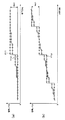
図5には、BPF301に入力される前後の信号の振幅イメージを示してある。図5(a)は入力前の映像信号の振幅を示しており、図5(b)は出力後の映像信号の振幅を示している。図5(a)に示した波形W1は、映像信号の8ビット量子化レベルにおける1ステップを示す波形イメージである。図5(a)に示した振幅レベルは、10ビット量子化時の映像信号における振幅レベルであり、8ビット量子化の1ステップが、10ビット量子化の4ステップにあたることが示されている。
FIG. 5 shows the amplitude images of the signals before and after being input to the
図5(b)には、図5(a)に示した波形W1を持つ映像信号が、BPF301を通過した後の波形イメージを示してある。図5(b)に示した映像信号は10ビットに伸張されており、図5(a)に示した波形W1の高域周波数成分が、振幅レベル±2の波形W2として抽出された様子を示してある。つまり、BPF301は、入力された映像信号のビット伸張を行い、振幅レベルが2までの小振幅の信号のみを通過させる。BPF301における入出力特性を、図6に実線A1として示してある。図6に示されるように、BPF301は、振幅レベルが±2までの入力信号については、入力された値に比例した値を出力し、±2以上の振幅レベルを持つ信号については、一律で2として出力する。
FIG. 5B shows a waveform image after the video signal having the waveform W1 shown in FIG. 5A passes through the
なお、図6には、±2以上の振幅レベルを持つ信号については、値がすべて±2として出力されるようなフィルタを用いた場合の特性を示してあるが、一定の振幅レベルを超える信号に対しては、出力をゼロとするようなフィルタに適用してもよい。例えば、入力信号の振幅レベルが所定レベル以上である場合には、振幅レベルの大きさに応じて出力を小さくし、所定の振幅レベルを超えた信号は、0として出力するようなフィルタを適用してもよい。 FIG. 6 shows the characteristics of a signal having an amplitude level of ± 2 or more when a filter that outputs all values as ± 2 is used, but the signal exceeds a certain amplitude level. May be applied to a filter whose output is zero. For example, when the amplitude level of the input signal is greater than or equal to a predetermined level, a filter is applied that reduces the output according to the magnitude of the amplitude level and outputs a signal that exceeds the predetermined amplitude level as 0. May be.
次に、同じく図6を参照して、リミッタ部302の処理について説明する。リミッタ部203は、BPF301から出力された10ビットの信号の振幅を制限して、階調を8ビット階調以下に制限する処理を行う。図6に、リミッタ部302における入出力信号の特性を、A2として一点鎖線で示してある。リミッタ部302は、A1として示したBPF301からの出力信号に対して、振幅レベルが±1までの信号に対してはリニアに出力し、振幅レベルが±1以上の信号は、一律に±1として出力する処理を行うことで、図6の中でA2として示された特性を持つ信号を出力する。
Next, processing of the
図7(a)に、リミッタ部302からの出力信号における振幅の波形イメージを示してある。図7(a)に破線W2として示してあるのは、BPF301からの出力信号における波形イメージであり、図5(b)に示したものと同じものである。この信号に対して、リミッタ部302で更に振幅制限処理をかけることにより、波形W3として示した±1の振幅を持つ信号が生成される。そして、図7(b)に波形W1として示した8ビットの本線信号から、加算器304で、リミッタ部302を通すことで得た波形W3の特性を持つ信号を減算することにより、図7(b)に波形W4として示した振幅を持つ信号を得ることができる。
FIG. 7A shows a waveform image of the amplitude in the output signal from the
このように構成することで得られたフィルタ31からの出力信号は、本線の映像信号のうち、微小振幅の信号に対してのみローパスフィルタが掛けられた信号と等価となる。擬似輪郭が発生するのは階調の変化が緩やかな部分であり、信号の振幅が少ない部分である。よって、映像信号の高域周波数成分にのみローパスフィルタを掛けることにより、画像全体をなまらせてしまうことなく、擬似輪郭のみを改善することができるようになる。
The output signal from the
本例では、リミッタ部302と加算器304との間にゲイン調整部303を設けてあり、ゲイン調整部303でゲインを設定することにより、本線の映像信号から減算する信号の大きさを調整することができるようにしてある。図8には、ゲイン調整部303におけるゲイン設定の例を示してある。ゲイン調整部303において、ゲインを1と設定した場合には、図8の中で線A3として示したように、入力値に比例した値が出力される。つまり、リミッタ部302から出力された信号の振幅が保たれたまま、加算器304によって、本線の映像信号から減算されるようになる。
In this example, a
ゲイン調整部303において、ゲインを0.5と設定した場合には、図8の中で線A4として示したように、入力値は1/2の値として出力されるようになる。この場合は、リミッタ部302からの出力信号のレベルが1/2に縮小されるため、加算器304で本線信号から減算される信号のレベルも小さくなる。
When the gain is set to 0.5 in the
また、ゲイン調整部303において、ゲインが0と設定された場合には、図8の中で線A5として示したように、リミッタ部302から出力された信号は、その大きさに係わらずすべて0として出力される。ゲイン調整部303の値は、操作部70(図2参照)等への操作入力に応じて、切り替わるようにしてある。よって、擬似輪郭補正の効果をオフにしたい場合などには、ゲイン調整部303でのゲインを0に設定すればよい。
Further, when the gain is set to 0 in the
なお、ゲイン調整部303におけるゲインの値は上述した3つの値に限定されるのではなく、任意の値を設定することができるものとする。また、本例ではリミッタ部302の後にゲイン調整部303を配置した構成を例に挙げたが、ゲイン調整部303の後にリミッタ部302を配置するようにしてもよい。また、リミッタ部302にゲイン調整の機能を持たせて、同時に処理を行ってもよい。
Note that the gain value in the
次に、本発明の第2の実施の形態を、図9〜図14を参照して説明する。本例の記録再生装置100は、注目画素とその周辺領域の画素とで構成される領域における、階調のなだらかさを判断することで、その領域で擬似輪郭が目立つか否かを判定し、その判定結果に応じてゲイン調整部303のゲイン値を変化させる構成としたものである。
Next, a second embodiment of the present invention will be described with reference to FIGS. The recording / reproducing
本例の構成を示す図9において、先に説明した図1に対応する部分には同一符号を付す。図9は、本例の記録再生装置におけるフィルタ部31の構成例を示した図である。本例の記録再生装置の基本的な構成については、上述した図1に示したフィルタ部31と同じ構成としてある。即ち、入力信号に対してビット伸張処理及び高域周波数成分の抽出を行うBPF301と、BPF301から出力された信号に対して振幅制限処理を施すリミッタ部302と、リミッタ部302からの出力値の出力レベルを調整するゲイン調整部303と、ゲイン調整部303からの出力信号を、本線信号から減算する加算器304を備える。
In FIG. 9 showing the configuration of this example, the same reference numerals are given to the portions corresponding to FIG. 1 described above. FIG. 9 is a diagram illustrating a configuration example of the
本例では、上述した構成に加えて、本線の映像信号を検出して擬似輪郭発生の有無を判定する擬似輪郭判定部305を備えたことを特徴とする。擬似輪郭判定部305の判定結果はゲイン調整部303に出力され、ゲイン調整部303では、擬似輪郭判定部305から入力される判定結果に応じて、ゲインの値が変更される構成としてある。
In this example, in addition to the configuration described above, a pseudo
擬似輪郭判定部305は、入力される画素の1つを注目画素と設定し、水平方向におけるその周辺画素との関係を判断することで、判断に用いた箇所が擬似輪郭として目立つか否かの判定を行う。擬似輪郭として目立つか否かの判定は、3つの判断基準を基に行うようにしてあり、その手順を図10にフローチャートで示してある。ステップS1では、まず、注目画素の周辺画素における信号レベルが、水平方向で単調増加もしくは単調減少しているか否かが判定される。注目画素の周辺における各画素の信号レベルが、単調増加もしくは単調減少していると判定された場合には“Yes”が選択され、ゲイン調整部303のゲインを1等の所定の値に設定する処理が行われる(ステップS4)。
The pseudo
ステップS1で“No”が選択された場合には、次に、注目画素と注目画素の左右隣接画素との信号レベル差が、その近傍の画素で構成される領域における信号レベルの変化量の大きさ(アクティビティ)に比べて、小さいか否かが判定される。注目画素と注目画素の左右隣接画素との信号レベル差が、その近傍の領域におけるアクティビティに比べて大きい場合と判定された場合には、ステップS4に進み、ゲイン調整部303のゲインが所定の値に設定される。
If “No” is selected in step S1, then the signal level difference between the target pixel and the adjacent pixels on the left and right of the target pixel is large in the amount of change in the signal level in the region composed of the neighboring pixels. It is determined whether it is smaller than (activity). If it is determined that the signal level difference between the target pixel and the left and right adjacent pixels of the target pixel is larger than the activity in the neighboring area, the process proceeds to step S4, and the gain of the
ステップS2で“No”が選択された場合には、次に、より広範囲の周辺画素で構成される領域におけるアクティビティが、閾値として設定された値以下であるかの判定が行われる。より広範囲の周辺画素におけるアクティビティが、閾値以下であると判定された場合には、ステップS4に進み、ゲイン調整部303のゲインが所定の値に設定される。
If “No” is selected in step S2, it is next determined whether or not the activity in the area composed of a wider range of peripheral pixels is less than or equal to the value set as the threshold value. When it is determined that the activity in a wider range of peripheral pixels is equal to or less than the threshold value, the process proceeds to step S4, and the gain of the
つまり擬似輪郭判定部305は、ステップS1、ステップS2、ステップS3で行われる判定のうち、どれか1つでも“Yes”が選択された場合には擬似輪郭が発生しているものとみなし、ゲイン調整部305のゲイン設定値を所定の値にする処理を行う。なお、図10では、それぞれの判定を順番に行うようにしてあるが、ここに示した順番に限定されるものではなく、また、3つの判定を並行して行うようにしてもよい。
In other words, the pseudo
次に、図10にステップS1、ステップS2、ステップS3として示したそれぞれの判定処理の詳細について、図11〜図14を参照して説明する。各ステップでの判定は、まず判断に用いる画素間の信号レベルの差を算出し、その値を所定の条件式にかけることにより行われる。図11には、注目画素P10とその周辺10画素との水平方向での位置関係を示してあり、各画素における隣接画素との差分を、diff_Ln又はdiff_Rn(いずれもnは整数)として示してある。注目画素P10の信号レベルと、右隣の画素P11の信号レベルとの差はdiff_R0として示してあり、注目画素P10の信号レベルと、左隣の画素P11の信号レベルとの差はdiff_L0として示してある。 Next, details of the determination processes shown as step S1, step S2, and step S3 in FIG. 10 will be described with reference to FIGS. The determination in each step is performed by first calculating a signal level difference between pixels used for the determination and applying the value to a predetermined conditional expression. FIG. 11 shows the positional relationship between the pixel of interest P10 and its surrounding 10 pixels in the horizontal direction, and the difference between adjacent pixels in each pixel is shown as diff_Ln or diff_Rn (both are integers). . The difference between the signal level of the target pixel P10 and the signal level of the right adjacent pixel P11 is shown as diff_R0, and the difference between the signal level of the target pixel P10 and the signal level of the left adjacent pixel P11 is shown as diff_L0. is there.
各画素における信号レベルをin、注目画素の水平方向における位置を[x]とした場合に、diff_Ln又はdiff_Rnの値は下記の計算式で求められる。
diff_L9 = in[x-10] - in[x-9]
diff_L8 = in[x-9] - in[x-8]
diff_L7 = in[x-8] - in[x-7]
diff_L6 = in[x-7] - in[x-6]
diff_L5 = in[x-6] - in[x-5]
diff_L4 = in[x-5] - in[x-4]
diff_L3 = in[x-4] - in[x-3]
diff_L2 = in[x-3] - in[x-2]
diff_L1 = in[x-2] - in[x-1]
diff_L0 = in[x-1] - in[x]
diff_R0 = in[x] - in[x+1]
diff_R1 = in[x+1] - in[x+2]
diff_R2 = in[x+2] - in[x+3]
diff_R3 = in[x+3] - in[x+4]
diff_R4 = in[x+4] - in[x+5]
diff_R5 = in[x+5] - in[x+6]
diff_R6 = in[x+6] - in[x+7]
diff_R7 = in[x+7] - in[x+8]
diff_R8 = in[x+8] - in[x+9]
diff_R9 = in[x+9] - in[x+10]
When the signal level in each pixel is in and the position in the horizontal direction of the target pixel is [x], the value of diff_Ln or diff_Rn can be obtained by the following calculation formula.
diff_L9 = in [x-10]-in [x-9]
diff_L8 = in [x-9]-in [x-8]
diff_L7 = in [x-8]-in [x-7]
diff_L6 = in [x-7]-in [x-6]
diff_L5 = in [x-6]-in [x-5]
diff_L4 = in [x-5]-in [x-4]
diff_L3 = in [x-4]-in [x-3]
diff_L2 = in [x-3]-in [x-2]
diff_L1 = in [x-2]-in [x-1]
diff_L0 = in [x-1]-in [x]
diff_R0 = in [x]-in [x + 1]
diff_R1 = in [x + 1]-in [x + 2]
diff_R2 = in [x + 2]-in [x + 3]
diff_R3 = in [x + 3]-in [x + 4]
diff_R4 = in [x + 4]-in [x + 5]
diff_R5 = in [x + 5]-in [x + 6]
diff_R6 = in [x + 6]-in [x + 7]
diff_R7 = in [x + 7]-in [x + 8]
diff_R8 = in [x + 8]-in [x + 9]
diff_R9 = in [x + 9]-in [x + 10]
図10のステップS1における、注目画素P10の周辺の各画素における信号レベルが、水平方向において単調増加或いは単調減少しているか否かの判断は、例えば注目画素P10及びその左右隣接3画素を対象として行う。まず注目画素P10及びその左右隣接3画素のそれぞれにおける、隣接画素との信号レベルの差分を求め、次に、求められた差分の各値がすべて0以上であるか、又はすべて0以下であるかの判断を行う。実際に用いられる式としては、例えば下記のようなものになる。条件式が満たされた場合にはdet_slope_hと定義された変数に1を代入し、条件式が満たされない場合には、det_slope_hに0を代入するようにしてある。
If (((diff_L2 >=0)&&(diff_L1 >=0)&&
(diff_L0 >=0)&&(diff_R0 >=0)&&
(diff_R1 >=0)&&(diff_R2 >=0)) ||
((diff_L2 <=0)&&(diff_L1 <=0)&&
(diff_L0 <=0)&&(diff_R0 <=0)&&
(diff_R1 <=0)&&(diff_R2 <=0))) {
det_slope_h= 1;
} else {
det_slope_h= 0;
}
In step S1 of FIG. 10, whether or not the signal level at each pixel around the pixel of interest P10 is monotonously increasing or monotonically decreasing in the horizontal direction is determined with respect to the pixel of interest P10 and its three adjacent pixels on the left and right sides, for example. Do. First, the difference in signal level between the target pixel P10 and the three adjacent pixels on the right and left sides with the adjacent pixel is obtained, and then whether the obtained difference values are all 0 or more or all 0 or less. Make a decision. For example, the following formula is actually used. When the conditional expression is satisfied, 1 is substituted into a variable defined as det_slope_h, and when the conditional expression is not satisfied, 0 is substituted into det_slope_h.
If (((diff_L2> = 0) &&(diff_L1> = 0) &&
(diff_L0> = 0) &&(diff_R0> = 0) &&
(diff_R1> = 0) &&(diff_R2> = 0)) ||
((diff_L2 <= 0) && (diff_L1 <= 0) &&
(diff_L0 <= 0) && (diff_R0 <= 0) &&
(diff_R1 <= 0) && (diff_R2 <= 0))) {
det_slope_h = 1;
} else {
det_slope_h = 0;
}
図12(a)〜(d)には、上記条件式が満たされる場合の具体的な例を示してある。図13においては、縦軸に信号レベルを、横軸に画素の水平方向をとってある。図13(a)に示した例では、注目画素P10の信号レベルと、その右隣の画素P11の信号レベルとの差を示すdiff_R0のみが−1を示し、diff_L2, diff_L1, diff_L0, diff_R1, diff_R2は0である。よって、差分の値のすべてが0以下となるため、上記条件式が満される。 12A to 12D show specific examples when the above conditional expression is satisfied. In FIG. 13, the vertical axis represents the signal level and the horizontal axis represents the horizontal direction of the pixel. In the example shown in FIG. 13A, only diff_R0 indicating the difference between the signal level of the pixel of interest P10 and the signal level of the pixel P11 on the right is −1, and diff_L2, diff_L1, diff_L0, diff_R1, diff_R2 Is 0. Therefore, since all the difference values are 0 or less, the above conditional expression is satisfied.
図12(b)に示した例では、diff_L2とdiff_R1が−1となり、diff_L1, diff_L0, diff_R0, diff_R2は0となる。よって、差分の値のすべてが0以下となり、上記条件式を満たす。図12(c)に示した例では、diff_L1とdiff_L0とdiff_R0とdiff_R2が1となり、diff_L2とdiff_R1は0となる。よって、差分の値のすべてが0以上となり、上記条件式を満たす。図12(d)に示した例では、diff_L2, diff_L1, diff_L0, diff_R0, diff_R1, diff_R2のすべての値が1となるため、上記条件式を満たす。 In the example shown in FIG. 12B, diff_L2 and diff_R1 are −1, and diff_L1, diff_L0, diff_R0, and diff_R2 are 0. Therefore, all the difference values are 0 or less, and the above conditional expression is satisfied. In the example shown in FIG. 12C, diff_L1, diff_L0, diff_R0, and diff_R2 are 1, and diff_L2 and diff_R1 are 0. Therefore, all the difference values are 0 or more, and the above conditional expression is satisfied. In the example shown in FIG. 12D, since all values of diff_L2, diff_L1, diff_L0, diff_R0, diff_R1, and diff_R2 are 1, the above conditional expression is satisfied.
次に、図10にステップS2として示した判断処理と、ステップS3として示した判断処理の詳細について説明する。これらの判定を行うにあたり、まず、注目画素及び注目画素に隣接する左右2画素で構成される領域におけるアクティビティと、注目画素の左右隣接3画素で構成される領域におけるアクティビティと、注目画素の左右10画素で構成される領域におけるアクティビティを求める。アクティビティとは、領域を構成する各画素における隣接画素との信号レベルの差を、絶対値和として示したものであり、下記計算式によって求めることが出来る。なお、下記式においては、注目画素を含む左右隣接2画素で構成される領域におけるアクティビティが代入される変数として act0_h、注目画素の左右3画素で構成される領域におけるアクティビティが代入される変数としてact1_2_h、注目画素の左右10画素で構成される領域におけるアクティビティが代入される変数としてact1_9_hを用いてある。また、下記式における“abs”とは、絶対値を求める関数である。 Next, the details of the determination process shown as step S2 in FIG. 10 and the determination process shown as step S3 will be described. In making these determinations, first, an activity in a region composed of a pixel of interest and two left and right pixels adjacent to the pixel of interest, an activity in a region composed of three pixels adjacent to the pixel of interest, and the left and right 10 The activity in the area composed of pixels is obtained. The activity indicates a difference in signal level between adjacent pixels in an area and adjacent pixels as an absolute value sum, and can be obtained by the following calculation formula. In the following equation, act0_h is a variable to which an activity in an area composed of two adjacent pixels including the target pixel is assigned, and act1_2_h is a variable to which an activity in an area composed of the three pixels on the right and left of the target pixel is substituted. In addition, act1_9_h is used as a variable to which the activity in the region composed of the left and right 10 pixels of the target pixel is substituted. Further, “abs” in the following equation is a function for obtaining an absolute value.
act0_h = abs(diff_L0) + abs(diff_R0)
act1_2_h = abs(diff_L2) + abs(diff_L1) + abs(diff_R1) + abs(diff_R2)
act1_9_h = abs(diff_L9) + abs(diff_L8) + abs(diff_L7) + abs(diff_L6) +
abs(diff_L5) + abs(diff_L4) + abs(diff_L3) + abs(diff_L2) +
abs(diff_L1) + abs(diff_R1) + abs(diff_R2) + abs(diff_R3) +
abs(diff_R4) + abs(diff_R5) + abs(diff_R6) + abs(diff_R7) +
abs(diff_R8) + abs(diff_R9)
なお、上記式においては、act1_2_hとact1_9_hの構成要素に、注目画素と隣接する左右の画素と注目画素との信号レベル差を示すdiff_L0及びdiff_R0を含めない構成としてあるが、これらも含めて計算するようにしてもよい。
act0_h = abs (diff_L0) + abs (diff_R0)
act1_2_h = abs (diff_L2) + abs (diff_L1) + abs (diff_R1) + abs (diff_R2)
act1_9_h = abs (diff_L9) + abs (diff_L8) + abs (diff_L7) + abs (diff_L6) +
abs (diff_L5) + abs (diff_L4) + abs (diff_L3) + abs (diff_L2) +
abs (diff_L1) + abs (diff_R1) + abs (diff_R2) + abs (diff_R3) +
abs (diff_R4) + abs (diff_R5) + abs (diff_R6) + abs (diff_R7) +
abs (diff_R8) + abs (diff_R9)
In the above formula, the components of act1_2_h and act1_9_h are configured not to include diff_L0 and diff_R0 indicating the signal level difference between the pixel of interest and the left and right pixels adjacent to the pixel of interest. You may do it.
図10にステップS2として示した判断処理、つまり、注目画素と注目画素の左右画素との信号レベル差が、その近傍の領域(この場合は左右3画素)におけるアクティビティに比べて小さいか否かの判断処理には、例えば下記のような条件式が用いられる。
If (act0_h > act1_2_h) {
det_act1_2_h = 1;
} else {
det_act1_2_h = 0;
}
上記式によると、注目画素と、注目画素に隣接する左右の画素との信号レベル差を示すact0_hの値が、注目画素の左右3画素で構成される領域におけるアクティビティを示すact1_2_hよりも大きい場合に、det_act1_2_hと定義された変数に1が代入され、act1_2_h以下である場合に、det_act1_2_hに0が代入される。つまり、注目画素及びその左右の画素で構成される領域での階調の変化より、注目画素の左右3画素で構成される領域での階調の変化がなだらかである場合に、det_act1_2_hは1となる。そして、det_act1_2_hの値は、擬似輪郭判定部305からゲイン調整部303に出力される。
Whether or not the determination process shown as step S2 in FIG. 10, that is, whether the signal level difference between the target pixel and the left and right pixels of the target pixel is smaller than the activity in the neighboring region (in this case, the three left and right pixels) For example, the following conditional expression is used for the determination process.
If (act0_h> act1_2_h) {
det_act1_2_h = 1;
} else {
det_act1_2_h = 0;
}
According to the above formula, when the value of act0_h indicating the signal level difference between the target pixel and the left and right pixels adjacent to the target pixel is larger than act1_2_h indicating the activity in the region composed of the left and right three pixels of the target pixel. , 1 is assigned to a variable defined as det_act1_2_h, and 0 or less is assigned to det_act1_2_h when it is less than or equal to act1_2_h. That is, det_act1_2_h is 1 when the change in gradation in the region composed of the left and right three pixels of the target pixel is gentler than the change in gradation in the region composed of the target pixel and its left and right pixels. Become. The value of det_act1_2_h is output from the pseudo
図13(a)〜(e)には、上記条件式が満たされる場合の具体的な例を示してある。図13においても、縦軸に信号レベルを、横軸に画素の水平方向をとってある。図13(a)に示した例では、diff_R0のみが−(マイナス)1であり、他の値は0となるため、diff_R0を含むact0_hの値は1、act1_2_hの値は0となる。よって、act0_h > act1_2_hの条件が満たされる。 FIGS. 13A to 13E show specific examples when the above conditional expression is satisfied. Also in FIG. 13, the vertical axis represents the signal level and the horizontal axis represents the horizontal direction of the pixel. In the example shown in FIG. 13A, only diff_R0 is − (minus) 1 and other values are 0. Therefore, the value of act0_h including diff_R0 is 1, and the value of act1_2_h is 0. Therefore, the condition of act0_h> act1_2_h is satisfied.
図13(b)に示した例では、
act0_h = 1(diff_L0の絶対値) + 1(diff_R0の絶対値) = 2
act1_2_h = 0(diff_L2の絶対値) + 1(diff_L1の絶対値)
+ 0(diff_R1の絶対値) + 0(diff_R2の絶対値) = 1
となるため、act0_h > act1_2_hの条件が満たされる。
In the example shown in FIG.
act0_h = 1 (absolute value of diff_L0) + 1 (absolute value of diff_R0) = 2
act1_2_h = 0 (absolute value of diff_L2) + 1 (absolute value of diff_L1)
+ 0 (absolute value of diff_R1) + 0 (absolute value of diff_R2) = 1
Therefore, the condition of act0_h> act1_2_h is satisfied.
図13(c)に示した例では、
act0_h = 1(diff_L0の絶対値) + 1(diff_R0の絶対値) = 2
act1_2_h = 0(diff_L2の絶対値) + 0(diff_L1の絶対値)
+ 1(diff_R1の絶対値) + 0(diff_R2の絶対値) = 1
となるため、act0_h > act1_2_hの条件が満たされる。
In the example shown in FIG.
act0_h = 1 (absolute value of diff_L0) + 1 (absolute value of diff_R0) = 2
act1_2_h = 0 (absolute value of diff_L2) + 0 (absolute value of diff_L1)
+ 1 (absolute value of diff_R1) + 0 (absolute value of diff_R2) = 1
Therefore, the condition of act0_h> act1_2_h is satisfied.
図13(d)に示した例では、
act0_h = 1(diff_L0の絶対値) + 1(diff_R0の絶対値) = 2
act1_2_h = 1(diff_L2の絶対値) + 0(diff_L1の絶対値)
+ 0(diff_R1の絶対値) + 0(diff_R2の絶対値) = 1
となるため、act0_h > act1_2_hの条件が満たされる。
In the example shown in FIG.
act0_h = 1 (absolute value of diff_L0) + 1 (absolute value of diff_R0) = 2
act1_2_h = 1 (absolute value of diff_L2) + 0 (absolute value of diff_L1)
+ 0 (absolute value of diff_R1) + 0 (absolute value of diff_R2) = 1
Therefore, the condition of act0_h> act1_2_h is satisfied.
図13(e)に示した例では、
act0_h = 1(diff_L0の絶対値) + 1(diff_R0の絶対値) = 2
act1_2_h = 0(diff_L2の絶対値) + 0(diff_L1の絶対値)
+ 0(diff_R1の絶対値) + 1(diff_R2の絶対値) = 1
となるため、act0_h > act1_2_hの条件が満たされる。
In the example shown in FIG.
act0_h = 1 (absolute value of diff_L0) + 1 (absolute value of diff_R0) = 2
act1_2_h = 0 (absolute value of diff_L2) + 0 (absolute value of diff_L1)
+ 0 (absolute value of diff_R1) + 1 (absolute value of diff_R2) = 1
Therefore, the condition of act0_h> act1_2_h is satisfied.
なお、act0_hとact1_2_hとでは、扱う領域の広さが異なるため、両方を等価に扱えるように、act0_hとact1_2_hのいずれか一方の値に対して重み付けを行うようにしてもよい。本例では、act0_hの要素が2、act1_2_hの要素が4であるため、act1_2_hに0.5等の係数をかけるようにしてもよい。 Since act0_h and act1_2_h have different area sizes, weighting may be applied to one of act0_h and act1_2_h so that both can be handled equally. In this example, the element of act0_h is 2, and the element of act1_2_h is 4. Therefore, a factor such as 0.5 may be applied to act1_2_h.
図10にステップS3として示した判断処理、つまり、注目画素の左右10画素で構成される領域におけるアクティビティが、閾値以下であるか判断処理には、例えば下記のような条件式が用いられる。閾値としては、DET_ACT1_9_THという変数を用いてあり、値としては、例えば「3」等を設定してあるものとする。
If (act1_9_h <= DET_ACT1_9_TH) {
det_act1_9_h = 1;
} else {
det_act1_9_h = 0;
}
この式においては、注目画素の左右10画素で構成される領域におけるアクティビティを示すact1_9_hが、閾値(この場合は3)以下である場合に、det_act1_9_hに1が代入される。つまり、注目画素の周辺の比較的広い範囲に注目した場合に、その領域で表現される階調の変化がなだらかである場合に、det_act1_9_hの値が1となる。
For example, the following conditional expression is used in the determination process shown as step S3 in FIG. 10, that is, the determination process of whether the activity in the area formed by the left and right 10 pixels of the target pixel is equal to or less than the threshold value. It is assumed that a variable DET_ACT1_9_TH is used as the threshold, and “3” or the like is set as the value.
If (act1_9_h <= DET_ACT1_9_TH) {
det_act1_9_h = 1;
} else {
det_act1_9_h = 0;
}
In this equation, 1 is substituted into det_act1_9_h when the act1_9_h indicating the activity in the area composed of the 10 pixels on the left and right of the target pixel is equal to or less than the threshold value (3 in this case). That is, when attention is paid to a relatively wide range around the pixel of interest, the value of det_act1_9_h is 1 when the change in gradation expressed in the region is gentle.
図14(a)〜(d)には、上記条件式が満たされる場合の具体的な例を示してある。図14においても、縦軸に信号レベルを、横軸に画素の水平方向をとってある。図14(a)に示した例では、diff_R0の値が1であるが、act1_9_hを求める式にはdiff_R0を含んでいないため、act1_9_h=0となる。よって、act1_9_h <= DET_ACT1_9_THの条件が満たされる。 FIGS. 14A to 14D show specific examples when the above conditional expression is satisfied. Also in FIG. 14, the vertical axis represents the signal level and the horizontal axis represents the horizontal direction of the pixel. In the example shown in FIG. 14A, the value of diff_R0 is 1, but since diff_R0 is not included in the expression for calculating act1_9_h, act1_9_h = 0. Therefore, the condition of act1_9_h <= DET_ACT1_9_TH is satisfied.
図14(b)に示した例では、
act1_9_h = 0(diff_L9の絶対値) + 0(diff_L8の絶対値) + 0(diff_L7の絶対値) +
0(diff_L6の絶対値) + 1(diff_L5の絶対値) + 0(diff_L4の絶対値) +
0(diff_L3の絶対値) + 0(diff_L2の絶対値) + 0(diff_L1の絶対値) +
0(diff_R1の絶対値) + 0(diff_R2の絶対値) + 0(diff_R3の絶対値) +
0(diff_R4の絶対値) + 1(diff_R5の絶対値) + 0(diff_R6の絶対値) +
0(diff_R7の絶対値) + 1(diff_R8の絶対値) + 0(diff_R9の絶対値) = 3
となるため、act1_9_h <= DET_ACT1_9_THの条件が満たされる。
In the example shown in FIG.
act1_9_h = 0 (absolute value of diff_L9) + 0 (absolute value of diff_L8) + 0 (absolute value of diff_L7) +
0 (absolute value of diff_L6) + 1 (absolute value of diff_L5) + 0 (absolute value of diff_L4) +
0 (absolute value of diff_L3) + 0 (absolute value of diff_L2) + 0 (absolute value of diff_L1) +
0 (absolute value of diff_R1) + 0 (absolute value of diff_R2) + 0 (absolute value of diff_R3) +
0 (absolute value of diff_R4) + 1 (absolute value of diff_R5) + 0 (absolute value of diff_R6) +
0 (absolute value of diff_R7) + 1 (absolute value of diff_R8) + 0 (absolute value of diff_R9) = 3
Therefore, the condition of act1_9_h <= DET_ACT1_9_TH is satisfied.
図14(c)に示した例では、
act1_9_h = 0(diff_L9の絶対値) + 0(diff_L8の絶対値) + 0(diff_L7の絶対値) +
0(diff_L6の絶対値) + 0(diff_L5の絶対値) + 0(diff_L4の絶対値) +
0(diff_L3の絶対値) + 0(diff_L2の絶対値) + 0(diff_L1の絶対値) +
1(diff_R1の絶対値) + 1(diff_R2の絶対値) + 0(diff_R3の絶対値) +
1(diff_R4の絶対値) + 0(diff_R5の絶対値) + 0(diff_R6の絶対値) +
0(diff_R7の絶対値) + 0(diff_R8の絶対値) + 0(diff_R9の絶対値) = 3
となるため、act1_9_h <= DET_ACT1_9_THの条件が満たされる。
In the example shown in FIG.
act1_9_h = 0 (absolute value of diff_L9) + 0 (absolute value of diff_L8) + 0 (absolute value of diff_L7) +
0 (absolute value of diff_L6) + 0 (absolute value of diff_L5) + 0 (absolute value of diff_L4) +
0 (absolute value of diff_L3) + 0 (absolute value of diff_L2) + 0 (absolute value of diff_L1) +
1 (absolute value of diff_R1) + 1 (absolute value of diff_R2) + 0 (absolute value of diff_R3) +
1 (absolute value of diff_R4) + 0 (absolute value of diff_R5) + 0 (absolute value of diff_R6) +
0 (absolute value of diff_R7) + 0 (absolute value of diff_R8) + 0 (absolute value of diff_R9) = 3
Therefore, the condition of act1_9_h <= DET_ACT1_9_TH is satisfied.
図14(d)に示した例では、
act1_9_h = 0(diff_L9の絶対値) + 0(diff_L8の絶対値) + 0(diff_L7の絶対値) +
0(diff_L6の絶対値) + 0(diff_L5の絶対値) + 0(diff_L4の絶対値) +
1(diff_L3の絶対値) + 0(diff_L2の絶対値) + 0(diff_L1の絶対値) +
1(diff_R1の絶対値) + 1(diff_R2の絶対値) + 0(diff_R3の絶対値) +
0(diff_R4の絶対値) + 0(diff_R5の絶対値) + 0(diff_R6の絶対値) +
0(diff_R7の絶対値) + 0(diff_R8の絶対値) + 0(diff_R9の絶対値) = 3
となるため、act1_9_h <= DET_ACT1_9_THの条件が満たされる。
In the example shown in FIG.
act1_9_h = 0 (absolute value of diff_L9) + 0 (absolute value of diff_L8) + 0 (absolute value of diff_L7) +
0 (absolute value of diff_L6) + 0 (absolute value of diff_L5) + 0 (absolute value of diff_L4) +
1 (absolute value of diff_L3) + 0 (absolute value of diff_L2) + 0 (absolute value of diff_L1) +
1 (absolute value of diff_R1) + 1 (absolute value of diff_R2) + 0 (absolute value of diff_R3) +
0 (absolute value of diff_R4) + 0 (absolute value of diff_R5) + 0 (absolute value of diff_R6) +
0 (absolute value of diff_R7) + 0 (absolute value of diff_R8) + 0 (absolute value of diff_R9) = 3
Therefore, the condition of act1_9_h <= DET_ACT1_9_TH is satisfied.
このようにして求められたdet_slope_h, det_act1_2_h,det_act1_9_hの値のうち、どれか1つでも1であった場合には、擬似輪郭判定部305は擬似輪郭が発生しているものとみなし、ゲイン調整部303に対してゲインの値を引数として渡す処理を行う。この処理を実現させる具体的なプログラムは、例えば下記のようなものとなる。
If ((det_slope_h == 1) ||
(det_act1_2_h == 1) ||
(det_act1_9_h == 1)) {
gain_h = GAIN_LPF_H;
} else {
gain_h = 0;
}
この式によれば、det_slope_hの値が1もしくはdet_act1_2_hの値が1、もしくはdet_act1_9_hの値が1であった場合に、gain_hとして定義された変数に、GAIN_LPF_Hとして定義された定数が代入される。GAIN_LPF_Hには、予め例えば0≦GAIN_LPF_H≦1の範囲の値が設定してあるものとする。そして、det_slope_h, det_act1_2_h,det_act1_9_hのいずれの値も0であった場合には、gain_hには0が代入される。
If any one of the values of det_slope_h, det_act1_2_h, and det_act1_9_h thus determined is 1, the pseudo
If ((det_slope_h == 1) ||
(det_act1_2_h == 1) ||
(det_act1_9_h == 1)) {
gain_h = GAIN_LPF_H;
} else {
gain_h = 0;
}
According to this expression, when the value of det_slope_h is 1, the value of det_act1_2_h is 1, or the value of det_act1_9_h is 1, a constant defined as GAIN_LPF_H is assigned to the variable defined as gain_h. For example, a value in a range of 0 ≦ GAIN_LPF_H ≦ 1 is set in GAIN_LPF_H in advance. When all of det_slope_h, det_act1_2_h, and det_act1_9_h are 0, 0 is assigned to gain_h.
なお、上述した条件式では、det_slope_h,det_act1_2_h,det_act1_9_hのいずれかの値が1であったときに、gain_hにGAIN_LPF_Hが代入されるようにしてあり、3つの条件をOR条件でつないであるが、この例に限定されるものではない。例えば、3つの条件のすべてをAND条件でつないだり、一部をAND条件でつなぐような式を適用してもよい。具体的には、下記のような式が考えられる。
If (((det_slope_h == 1) ||
(det_act1_2_h == 1)) &&
(det_act1_9_h == 1)) {
gain_h = GAIN_LPF_H;
} else {
gain_h= 0;
}
または、下記の式を適用してもよい。
If ((det_slope_h== 1) &&
(det_act1_2_h == 1) &&
(det_act1_9_h == 1)) {
gain_h = GAIN_LPF_H;
} else {
gain_h= 0;
}
In the above-described conditional expression, when any value of det_slope_h, det_act1_2_h, and det_act1_9_h is 1, GAIN_LPF_H is assigned to gain_h, and the three conditions are connected by the OR condition. It is not limited to this example. For example, an expression that connects all three conditions with an AND condition or connects some with an AND condition may be applied. Specifically, the following formula can be considered.
If (((det_slope_h == 1) ||
(det_act1_2_h == 1)) &&
(det_act1_9_h == 1)) {
gain_h = GAIN_LPF_H;
} else {
gain_h = 0;
}
Alternatively, the following formula may be applied.
If ((det_slope_h == 1) &&
(det_act1_2_h == 1) &&
(det_act1_9_h == 1)) {
gain_h = GAIN_LPF_H;
} else {
gain_h = 0;
}
また、gain_hが採り得る値が、0又はGAIN_LPF_Hの2種類である場合を例に上げたが、定数を複数種類用意し、擬似輪郭判定部305から入力される判定結果の内容に応じて、適応する定数を変えるようにしてもよい。
In addition, although the case where the value that gain_h can take is two types of 0 or GAIN_LPF_H has been taken as an example, a plurality of constants are prepared and adapted according to the content of the determination result input from the pseudo
このような構成とすることにより、注目画素の周辺の領域において、各画素の信号レベルが単調増加あるいは単調減少している場合や、注目画素及びその左右隣接画素で構成される領域での階調の変化の大きさより、注目画素の左右3画素で構成される領域での階調の変化が小さい場合や、注目画素の周辺の比較的広い範囲において、階調の変化がなだらかである場合に、擬似輪郭が発生していると判断される。そして、ゲイン調整部303のゲイン設定値が所定の値に設定される。
With such a configuration, when the signal level of each pixel monotonously increases or decreases monotonously in the area around the target pixel, or in the area composed of the target pixel and its left and right adjacent pixels. If the change in gradation in the region composed of the left and right three pixels of the target pixel is smaller than the magnitude of the change in the target pixel, or if the change in gradation is gentle in a relatively wide range around the target pixel, It is determined that a pseudo contour has occurred. Then, the gain setting value of the
ゲイン調整部303のゲインが所定の値に設定されることにより、BPF301とリミッタ部302を通して得られた、階調が8ビット階調以下に制限された10ビットの微小振幅信号が、加算器304に出力されるようになる。そして加算器304で、本線の8ビットの映像信号から10ビットの微小振幅信号が減算される。これにより、加算器304から出力される信号は、ビットが伸張されて微小振幅部分のみが平滑化された信号となり、図示せぬ表示部等に表示される再生映像において、擬似輪郭が低減されるようになる。
By setting the gain of the
なお、ここまで説明した実施の形態では、8ビットの入力信号をBPF301で10ビットに伸張する例を挙げたが、ビット伸張のビット数はこれに限定されるものではなく、12ビットや14ビット等に伸張するようにしてもよい。入力信号を12ビットに伸張する場合の、BPF301とリミッタ部302とゲイン調整部303での処理の例について、図15〜図18を参照して説明する。
In the embodiment described so far, an example in which an 8-bit input signal is expanded to 10 bits by the
図15には、BPF301に入力される前後の信号の振幅を示してある。図15(a)は入力前の映像信号の振幅を示しており、図15(b)は出力後の映像信号の振幅を示している。図5(a)に示した波形W1′は、映像信号を8ビットで量子化した場合の1ステップを示す波形イメージである。図5(a)に示した振幅レベルは、12ビット量子化時の映像信号における振幅レベルであり、8ビット量子化の1ステップが、12ビット量子化の16ステップにあたることが示されている。
FIG. 15 shows the amplitudes of the signals before and after being input to the
図15(b)には、図15(a)に示した波形W1′の特性を持つ映像信号が、BPF301を通過した後の信号波形イメージを示してある。図15(b)に示した映像信号は12ビットに伸張されており、図15(a)に示した波形W1′の高域周波数成分が、振幅レベル±4の波形W2′として出力された様子を示してある。つまり、BPF301は、入力された映像信号のビット伸張を行い、振幅レベルが4までの小振幅の信号のみを通過させる。BPF301における入出力特性を、図16に実線A1′として示してある。図16に示されるように、BPF301は、入力信号における±6までの振幅については、入力された値に比例した値を出力し、±6以上の振幅レベルを持つ信号については、一律で±6として出力する。
FIG. 15B shows a signal waveform image after the video signal having the
図16には、リミッタ部302における入出力特性を破線A2′として示してある。リミッタ部302は、BPF301から出力された12ビットの信号の振幅を制限し、その階調を8ビット階調以下に制限する処理を行う。リミッタ部302は、A1′として示したBPF301からの出力信号に対して、振幅レベルが±2までの信号に対してはリニアに出力し、振幅レベルが±2以上の信号は、一律に±2として出力する処理を行うことで、図16の中でA2′として示された特性を持つ信号を出力する。
In FIG. 16, the input / output characteristics of the
図17(a)に、リミッタ部302からの出力信号における振幅の波形イメージを示してある。図17(a)に破線W2′として示してあるのは、BPF301からの出力信号における波形イメージであり、図15(b)に示したものと同じものである。この信号に対して、リミッタ部302で更に振幅制限処理をかけることにより、波形W3′として示した±2の振幅を持つ信号が生成される。そして、図17(b)に波形W1′として示した8ビットの本線信号に対して、加算器304(図1参照)で、リミッタ部302を通すことで得た波形W3′の特性を持つ信号を減算することにより、図7(b)に波形W4′として示した振幅を持つ信号を得ることができる。
FIG. 17A shows a waveform image of the amplitude in the output signal from the
図18には、ゲイン調整部303におけるゲイン設定の例を示してある。ゲイン調整部303において、ゲインを1と設定した場合には、図18の中で線A3′として示したように、入力値に比例した値が出力される。つまり、リミッタ部302から出力された信号の振幅が保たれたまま、加算器304によって、本線の映像信号から減算されるようになる。ゲイン調整部303において、ゲインを0.5と設定した場合には、図18の中で線A4′として示したように、入力値は1/2の値として出力されるようになる。例えば入力信号レベルが16である場合には、8として出力される。
FIG. 18 shows an example of gain setting in the
また、上述した実施の形態では、BPF301が使用する係数を固定とした場合を例に挙げたが、注目画素の周辺領域における、階調の変化の無い領域の広さ(平坦度合い)に応じて、BPF301で用いる係数を切り換えるようにしてもよい。この場合のフィルタ部31の構成例を、図19に示してある。図19において、先に説明した図1、図9に対応する部分には同一符号を付す。本例のフィルタ部31の基本的な構成については、上述した図9に示したフィルタ部31と同じ構成である。即ち、入力信号に対してビット伸張処理及び高域周波数成分の抽出を行うBPF301′と、BPF301′から出力された信号に対して振幅制限処理を施すリミッタ部302と、リミッタ部302からの出力値の出力レベルを調整するゲイン調整部303と、ゲイン調整部303からの出力信号を本線の映像信号から減算する加算器304と、本線の映像信号を検出して擬似輪郭発生の有無を判定する擬似輪郭判定部305′とを備える。
Further, in the above-described embodiment, the case where the coefficient used by the
本例では、擬似輪郭判定部305′による判定の結果を、BPF301′及びゲイン調整部303に出力するようにしてあり、擬似輪郭判定部305′の判定結果により、BPF301′におけるフィルタの種類や、ゲイン調整部303でのゲイン値が変更される構成としてある。
In this example, the determination result by the pseudo
図20には、BPF301′におけるフィルタ係数の例を示してある。なお、K0〜K16として示した係数と、画素の水平方向の位置との対応は、図4(a)に示したものと同様であるものとする。図20にM0として示したフィルタでは、画素信号P10を注目画素とした場合に、注目画素P10に対する係数K8には192/256を、注目画素から水平方向の左右4番目に位置する画素に掛ける係数K4と係数K12には−64/256を、注目画素から水平方向の左右8番目に位置する画素に掛ける係数K0と係数K16には−32/256を用いるものである。M1として示したフィルタは、図4(b)に示した係数と同一の係数を使用するものであり、画素信号P10を注目画素とした場合に、注目画素P10に対する係数K8には192/256を、注目画素から水平方向の左右2番目に位置する画素に掛ける係数K6と係数K10には−64/256を、注目画素から水平方向の左右8番目に位置する画素に掛ける係数K4と係数K12には−32/256を用いるものである。このように、フィルタM0とフィルタM1とでは時定数が異なるようにしてあり、これらの時定数の異なるフィルタを、状況に応じて切り替えるようにしてある。
FIG. 20 shows an example of filter coefficients in the
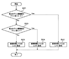
図21には、擬似輪郭判定部305におけるフィルタ切り換え判断の処理例を示す、フローチャートを示してある。擬似輪郭判定部305ではまず、注目画素における信号レベルと、注目画素に隣接する左右の画素における信号レベルとの差が、1であるか否かの判断が行われる(ステップS11)。図11に示した変数を用いて説明すると、diff_L0とdiff_R0のいずれかが1であるかの判断が行われる。diff_L0とdiff_R0のいずれの値も1ではない場合には“No”が選択され、ステップS12でゲイン調整部303のゲインの値が0に設定され、フィルタがオフにされる。
FIG. 21 is a flowchart illustrating a processing example of filter switching determination in the pseudo
diff_L0とdiff_R0のいずれかの値が1であった場合には“Yes”が選択され、次に注目画素の左右4画素のそれぞれにおける、隣接画素との信号レベルの差が0であるか否かの判断が行われる(ステップS13)。つまり、diff_L3,diff_L2,diff_L1,diff_R1,diff_R2,diff_R3のすべて値が、0であるか否かの判断が行われる。これらの値に、1つでも0以外の値があった場合は、“No”が選択されてステップS12に進み、フィルタがオフにされる。 If any value of diff_L0 and diff_R0 is 1, “Yes” is selected, and then whether or not the signal level difference between adjacent pixels in the left and right 4 pixels of the target pixel is 0 Is determined (step S13). That is, it is determined whether or not all the values of diff_L3, diff_L2, diff_L1, diff_R1, diff_R2, and diff_R3 are zero. If any of these values has a value other than 0, “No” is selected, the process proceeds to step S12, and the filter is turned off.
ステップS13で、diff_L3,diff_L2,diff_L1,diff_R1,diff_R2,diff_R3のすべて値が0であると判断された場合には、次に、注目画素の左右5画素目から8画素目の各画素における、隣接画素との信号レベルの差が0であるか否かの判断が行われる(ステップS14)。つまり、diff_L7,diff_L6,diff_L5,diff_L4,diff_R4,diff_R5,diff_R6,diff_R7のすべて値が、0であるか否かの判断が行われる。これらの値に、1つでも0以外の値があった場合は、“No”が選択されてステップS15に進み、BPF301で使用するフィルタとしてフィルタM1が選択される(ステップS15)。そして、ゲイン調整部303において、ゲインの値が所定の値に設定される(ステップS16)。
If it is determined in step S13 that all values of diff_L3, diff_L2, diff_L1, diff_R1, diff_R2, and diff_R3 are 0, next, the adjacent pixels in the fifth to eighth pixels of the pixel of interest are adjacent to each other. It is determined whether or not the difference in signal level from the pixel is 0 (step S14). That is, it is determined whether or not all the values of diff_L7, diff_L6, diff_L5, diff_L4, diff_R4, diff_R5, diff_R6, and diff_R7 are zero. If any of these values has a value other than 0, “No” is selected and the process proceeds to step S15, and the filter M1 is selected as a filter used in the BPF 301 (step S15). Then, the
ステップS14で、diff_L7,diff_L6,diff_L5,diff_L4,diff_R4,diff_R5,diff_R6,diff_R7のすべて値が、0であると判定された場合には、BPF301で使用するフィルタとしてフィルタM0が選択され(ステップS17)、ゲイン調整部303において、ゲインの値が所定の値に設定される(ステップS18)。
When it is determined in step S14 that all values of diff_L7, diff_L6, diff_L5, diff_L4, diff_R4, diff_R5, diff_R6, and diff_R7 are 0, the filter M0 is selected as a filter used in the BPF 301 (step S17). The
このように構成することにより、注目画素の周辺領域において、階調の変化の無い領域が広い場合には長時定数を持つフィルタM0が適用され、階調の変化が無い領域がそれほど広くない場合には、フィルタM1が適用されるようになる。フィルタM0が適用される場合とフィルタM1が適用される場合の具体的な例を、図22に示してある。図22において、8ビットの原信号における階調を破線で示してあり、ビット伸張後の信号における階調を実線で示してある。そして、8ビットの原信号における1LSB(Least Significant Bit)を、Wd1として示してある。図22に示した例においては、8ビットの入力信号を12ビットに伸張した場合を例に挙げてある。 With this configuration, when the region where the gradation does not change is wide in the peripheral region of the target pixel, the filter M0 having the long time constant is applied, and the region where the gradation does not change is not so wide. In this case, the filter M1 is applied. Specific examples of the case where the filter M0 is applied and the case where the filter M1 is applied are shown in FIG. In FIG. 22, the gradation in the 8-bit original signal is indicated by a broken line, and the gradation in the signal after bit expansion is indicated by a solid line. 1 LSB (Least Significant Bit) in the 8-bit original signal is indicated as Wd1. In the example shown in FIG. 22, the case where an 8-bit input signal is expanded to 12 bits is taken as an example.
図22(a)には、注目画素P10と右隣の画素P11との間に信号レベル1のレベル差があるのに対し、その周辺には階調の変化が無い場合の例を示してある。このような場合に時定数の長いフィルタM0が適用されることにより、注目画素P10と画素P11との間の段差とその周辺の平坦な領域とが、滑らかに繋がるようになる。図22(b)には、注目画素P10と右隣の画素P11との間に信号レベル1のレベル差があるのに対し、その周辺の画素間においても信号レベル1の差がある場合の例を示してある。このような場合には、時定数の短いフィルタM1が適用されることにより、注目画素P10と画素P11との間の段差と、段差及び平坦な領域とで構成される領域とが、滑らかに繋がるようになる。図21及び図22に示した例では2つのフィルタを切り替えて使用する例を挙げたが、注目画素周辺の領域の平坦度合いに応じて、複数種類のフィルタを切り替えて使用するようにしてもよい。
FIG. 22A shows an example in which there is a level difference of
また、上述した実施の形態では、サンプリングレートが4:4:4である場合を例に挙げて説明したが、4:2:2等、他のサンプリングレートを用いた場合に適用してもよい。サンプリングレートが4:2:2である場合には、輝度信号Yのデータはすべての画素が持つのに対し、クロマ信号Cbおよびクロマ信号Crのデータは奇数番目(又は偶数番目)の画素だけが持つようになるため、輝度信号とクロマ信号とで空間的な処理領域が異なることになる。本例においては、クロマ信号Cb及びクロマ信号Crにおける空間的な処理領域を、輝度信号Yと同一の処理領域にして処理を行うようにしてある。 In the above-described embodiment, the case where the sampling rate is 4: 4: 4 has been described as an example. However, the present invention may be applied to cases where other sampling rates such as 4: 2: 2 are used. . When the sampling rate is 4: 2: 2, the data of the luminance signal Y is held by all the pixels, whereas the data of the chroma signal Cb and the chroma signal Cr is only the odd-numbered (or even-numbered) pixels. Therefore, the spatial processing region differs between the luminance signal and the chroma signal. In this example, the spatial processing area in the chroma signal Cb and the chroma signal Cr is set to be the same processing area as that of the luminance signal Y for processing.
図23に、この場合のBPF301の構成例及び係数の例を示してある。図23(a)に示されるように、BPF301においては、画素P6の次には画素P8を入力し、画素P8の次には画素P10を入力するといったように、画素を1つおきに抽出するようにする。そして、入力された画素すべてに対して係数をかけるようにする。係数としては、例えば、注目画素P10に対する係数K2には192/256を、注目画素の左右隣に位置する画素に掛ける係数である係数K1と係数K3には−64/256を、注目画素から水平方向で左右2番目に位置する画素に掛ける係数である係数K0と係数K4には−32/256を用いる。
FIG. 23 shows a configuration example and coefficient examples of the
図24には、擬似輪郭判定処理部305での判定処理の基になる、diff_Ln又はdiff_Rnの値の設定例を示してある。上述したように、クロマ信号Cb又はクロマ信号Crのデータは、注目画素P10の右隣であれば画素P12、左隣であれば画素P8といったように、1つおきの画素に存在することになる。このため、注目画素P10の左側に隣接する画素との信号レベル差を示すdiff_L0は、画素P8と画素P10との差によって示され、diff_L4であれば、画素P0と画素P2との差によって示される。
FIG. 24 shows an example of setting the value of diff_Ln or diff_Rn, which is the basis of the determination process in the pseudo contour
各画素における信号レベルをin、注目画素の水平方向における位置を[x]とした場合、diff_Ln又はdiff_Rnは下記の式で示すことができる。なお下記式においては、クロマ信号Cbにおける隣接画素との信号レベルの差はCb_diff_Ln又はCb_diff_Rnで示し、クロマ信号Crにおける隣接画素との信号レベルの差はCr_diff_Ln又はCr_diff_Rnで示してある。
Cb_diff_L4 = Cb_in[x-10] - Cb_in[x-8]
Cb_diff_L3 = Cb_in[x-8] - Cb_in[x-6]
Cb_diff_L2 = Cb_in[x-6] - Cb_in[x-4]
Cb_diff_L1 = Cb_in[x-4] - Cb_in[x-2]
Cb_diff_L0 = Cb_in[x-2] - Cb_in[x]
Cb_diff_R0 = Cb_in[x] - Cb_in[x+2]
Cb_diff_R1 = Cb_in[x+2] - Cb_in[x+4]
Cb_diff_R2 = Cb_in[x+4] - Cb_in[x+6]
Cb_diff_R3 = Cb_in[x+6] - Cb_in[x+8]
Cb_diff_R4 = Cb_in[x+8] - Cb_in[x+10]
Cr_diff_L4 = Cr_in[x-10] - Cr_in[x-8]
Cr_diff_L3 = Cr_in[x-8] - Cr_in[x-6]
Cr_diff_L2 = Cr_in[x-6] - Cr_in[x-4]
Cr_diff_L1 = Cr_in[x-4] - Cr_in[x-2]
Cr_diff_L0 = Cr_in[x-2] - Cr_in[x]
Cr_diff_R0 = Cr_in[x] - Cr_in[x+2]
Cr_diff_R1 = Cr_in[x+2] - Cr_in[x+4]
Cr_diff_R2 = Cr_in[x+4] - Cr_in[x+6]
Cr_diff_R3 = Cr_in[x+6] - Cr_in[x+8]
Cr_diff_R4 = Cr_in[x+8] - Cr_in[x+10]
When the signal level in each pixel is in and the position in the horizontal direction of the target pixel is [x], diff_Ln or diff_Rn can be expressed by the following equation. In the following expression, the signal level difference between adjacent pixels in the chroma signal Cb is indicated by Cb_diff_Ln or Cb_diff_Rn, and the signal level difference between adjacent pixels in the chroma signal Cr is indicated by Cr_diff_Ln or Cr_diff_Rn.
Cb_diff_L4 = Cb_in [x-10]-Cb_in [x-8]
Cb_diff_L3 = Cb_in [x-8]-Cb_in [x-6]
Cb_diff_L2 = Cb_in [x-6]-Cb_in [x-4]
Cb_diff_L1 = Cb_in [x-4]-Cb_in [x-2]
Cb_diff_L0 = Cb_in [x-2]-Cb_in [x]
Cb_diff_R0 = Cb_in [x]-Cb_in [x + 2]
Cb_diff_R1 = Cb_in [x + 2]-Cb_in [x + 4]
Cb_diff_R2 = Cb_in [x + 4]-Cb_in [x + 6]
Cb_diff_R3 = Cb_in [x + 6]-Cb_in [x + 8]
Cb_diff_R4 = Cb_in [x + 8]-Cb_in [x + 10]
Cr_diff_L4 = Cr_in [x-10]-Cr_in [x-8]
Cr_diff_L3 = Cr_in [x-8]-Cr_in [x-6]
Cr_diff_L2 = Cr_in [x-6]-Cr_in [x-4]
Cr_diff_L1 = Cr_in [x-4]-Cr_in [x-2]
Cr_diff_L0 = Cr_in [x-2]-Cr_in [x]
Cr_diff_R0 = Cr_in [x]-Cr_in [x + 2]
Cr_diff_R1 = Cr_in [x + 2]-Cr_in [x + 4]
Cr_diff_R2 = Cr_in [x + 4]-Cr_in [x + 6]
Cr_diff_R3 = Cr_in [x + 6]-Cr_in [x + 8]
Cr_diff_R4 = Cr_in [x + 8]-Cr_in [x + 10]
擬似輪郭が発生しているか否かの判定は、図10のフローチャートに示した手順と同様の手順で行うようにする。図10のステップS1における、注目画素P10の周辺画素における信号レベルが、水平方向で単調増加或いは単調減少しているか否かの判断には、例えば下記の式を用いるようにする。条件式が満たされた場合にはC_det_slope_hと定義された変数には1が代入され、条件式が満たされない場合には、C_det_slope_hには0が代入される。
If (((Cb_diff_L2 >=0)&&(Cb_diff_L1 >=0)&&
(Cb_diff_L0 >=0)&&(Cb_diff_R0 >=0)&&
(Cb_diff_R1 >=0)&&(Cb_diff_R2 >=0)) ||
((Cb_diff_L2 <=0)&&(Cb_diff_L1 <=0)&&
(Cb_diff_L0 <=0)&&(Cb_diff_R0 <=0)&&
(Cb_diff_R1 <=0)&&(Cb_diff_R2 <=0)) ||
((Cr_diff_L2 >=0)&&(Cr_diff_L1 >=0)&&
(Cr_diff_L0 >=0)&&(Cr_diff_R0 >=0)&&
(Cr_diff_R1 >=0)&&(Cr_diff_R2 >=0)) ||
((Cr_diff_L2 <=0)&&(Cr_diff_L1 <=0)&&
(Cr_diff_L0 <=0)&&(Cr_diff_R0 <=0)&&
(Cr_diff_R1 <=0)&&(Cr_diff_R2 <=0))) {
C_det_slope_h = 1;
} else {
C_det_slope_h = 0;
}
Whether or not a pseudo contour has occurred is determined in the same procedure as that shown in the flowchart of FIG. For example, the following equation is used to determine whether or not the signal level in the peripheral pixels of the target pixel P10 in the step S1 in FIG. 10 is monotonously increasing or monotonically decreasing in the horizontal direction. When the conditional expression is satisfied, 1 is assigned to a variable defined as C_det_slope_h, and when the conditional expression is not satisfied, 0 is assigned to C_det_slope_h.
If (((Cb_diff_L2> = 0) &&(Cb_diff_L1> = 0) &&
(Cb_diff_L0> = 0) &&(Cb_diff_R0> = 0) &&
(Cb_diff_R1> = 0) &&(Cb_diff_R2> = 0)) ||
((Cb_diff_L2 <= 0) && (Cb_diff_L1 <= 0) &&
(Cb_diff_L0 <= 0) && (Cb_diff_R0 <= 0) &&
(Cb_diff_R1 <= 0) && (Cb_diff_R2 <= 0)) ||
((Cr_diff_L2> = 0) &&(Cr_diff_L1> = 0) &&
(Cr_diff_L0> = 0) &&(Cr_diff_R0> = 0) &&
(Cr_diff_R1> = 0) &&(Cr_diff_R2> = 0)) ||
((Cr_diff_L2 <= 0) && (Cr_diff_L1 <= 0) &&
(Cr_diff_L0 <= 0) && (Cr_diff_R0 <= 0) &&
(Cr_diff_R1 <= 0) && (Cr_diff_R2 <= 0))) {
C_det_slope_h = 1;
} else {
C_det_slope_h = 0;
}
つまりクロマ信号Cb又はクロマ信号Crのいずれかにおいて、diff_L2,diff_L1,diff_L0,diff_L0,diff_L1,diff_R2のすべての値が0以上、又は0以下であった場合に、C_det_slope_hに1が代入される。 That is, in any of the chroma signal Cb and the chroma signal Cr, 1 is assigned to C_det_slope_h when all the values of diff_L2, diff_L1, diff_L0, diff_L0, diff_L1, and diff_R2 are 0 or more or 0 or less.
図10のステップS2、ステップS3の判断に用いられる、act0_h,act1_2h,act1_9hで表現される各アクティビティは、下記式で求めるようにする。各領域におけるアクティビティは、クロマ信号Cbとクロマ信号Crの両方を用いて表現するようにしてあり、act0_hはC_act0_h、act1_2hはC_act1_2h、act1_9hはC_act1_9hと表現してある。
C_act0_h = abs(Cb_diff_L0) + abs(Cb_diff_R0) +
abs(Cr_diff_L0) + abs(Cr_diff_R0);
C_act1_2_h = abs(Cb_diff_L2) + abs(Cb_diff_L1) +
abs(Cb_diff_R1) + abs(Cb_diff_R2) +
abs(Cr_diff_L2) + abs(Cr_diff_L1) +
abs(Cr_diff_R1) + abs(Cr_diff_R2);
C_act1_9_h = abs(Cb_diff_L4) + abs(Cb_diff_L3) +
abs(Cb_diff_L2) + abs(Cb_diff_L1) +
abs(Cb_diff_R1) + abs(Cb_diff_R2) +
abs(Cb_diff_R3) + abs(Cb_diff_R4) +
abs(Cr_diff_L4) + abs(Cr_diff_L3) +
abs(Cr_diff_L2) + abs(Cr_diff_L1) +
abs(Cr_diff_R1) + abs(Cr_diff_R2) +
abs(Cr_diff_R3) + abs(Cr_diff_R4);
Each activity represented by act0_h, act1_2h, and act1_9h, which is used in the determinations in steps S2 and S3 in FIG. The activity in each area is expressed using both the chroma signal Cb and the chroma signal Cr. Act0_h is expressed as C_act0_h, act1_2h is expressed as C_act1_2h, and act1_9h is expressed as C_act1_9h.
C_act0_h = abs (Cb_diff_L0) + abs (Cb_diff_R0) +
abs (Cr_diff_L0) + abs (Cr_diff_R0);
C_act1_2_h = abs (Cb_diff_L2) + abs (Cb_diff_L1) +
abs (Cb_diff_R1) + abs (Cb_diff_R2) +
abs (Cr_diff_L2) + abs (Cr_diff_L1) +
abs (Cr_diff_R1) + abs (Cr_diff_R2);
C_act1_9_h = abs (Cb_diff_L4) + abs (Cb_diff_L3) +
abs (Cb_diff_L2) + abs (Cb_diff_L1) +
abs (Cb_diff_R1) + abs (Cb_diff_R2) +
abs (Cb_diff_R3) + abs (Cb_diff_R4) +
abs (Cr_diff_L4) + abs (Cr_diff_L3) +
abs (Cr_diff_L2) + abs (Cr_diff_L1) +
abs (Cr_diff_R1) + abs (Cr_diff_R2) +
abs (Cr_diff_R3) + abs (Cr_diff_R4);
そして、図10のステップS2における、注目画素と注目画素の左右画素との信号レベル差が、その近傍の所定の広さの領域におけるアクティビティの大きさに比べて小さいか否かの判定には、例えば下記の式を用いるものとする。
If (C_act0_h > C_act1_2_h) {
C_det_act1_2_h = 1;
} else {
C_det_act1_2_h = 0;
}
この場合も、C_act0_h又はC_act1_2hのいずれかの値に重み付けを行うようにしてもよい。
Then, in step S2 of FIG. 10, in determining whether the signal level difference between the target pixel and the left and right pixels of the target pixel is smaller than the magnitude of the activity in a predetermined area in the vicinity thereof, For example, the following formula is used.
If (C_act0_h> C_act1_2_h) {
C_det_act1_2_h = 1;
} else {
C_det_act1_2_h = 0;
}
In this case as well, weighting may be performed on either value of C_act0_h or C_act1_2h.
また、図10のステップS3における、注目画素の左右10画素で構成される領域におけるアクティビティが、閾値以下であるかの判断処理には、下記の条件式を用いるものとする。
If (C_act1_9_h <= DET_C_ACT1_9_TH) {
C_det_act1_9_h = 1;
} else {
C_det_act1_9_h = 0;
}
In addition, the following conditional expression is used for the determination process of whether or not the activity in the region composed of the left and right 10 pixels of the target pixel in step S3 in FIG.
If (C_act1_9_h <= DET_C_ACT1_9_TH) {
C_det_act1_9_h = 1;
} else {
C_det_act1_9_h = 0;
}
そして擬似輪郭判定部305は、このようにして求められたC_det_slope_h, C_det_act1_2_h,C_det_act1_9_hの値のうち、どれか1つでも1であった場合には、擬似輪郭が発生しているものとみなし、ゲイン調整部303に対してゲインの値を引数として渡す処理を行う。この処理を実現させる具体的なプログラムは、例えば下記のようなものとなる。
If ((C_det_slope_h== 1) ||
(C_det_act1_2_h == 1) ||
(C_det_act1_9_h == 1) {
C_gain_h = C_GAIN_LPF_H;
} else {
C_gain_h = 0;
}
Then, if any one of the values of C_det_slope_h, C_det_act1_2_h, and C_det_act1_9_h obtained in this way is 1, the pseudo
If ((C_det_slope_h == 1) ||
(C_det_act1_2_h == 1) ||
(C_det_act1_9_h == 1) {
C_gain_h = C_GAIN_LPF_H;
} else {
C_gain_h = 0;
}
C_GAIN_LPF_Hの採り得る値は、GAIN_LPF_Hの場合と同様に0以上1以下等とする。なお、C_gain_hにC_GAIN_LPF_Hが代入された場合には、クロマ信号Cbとクロマ信号Crのいずれか一方に対してフィルタ処理を行うのではなく、ペアとなるクロマ信号Cbとクロマ信号Crの両方に対して、同様の処理を施すようにする。 The value that C_GAIN_LPF_H can take is set to 0 or more and 1 or less as in the case of GAIN_LPF_H. When C_GAIN_LPF_H is assigned to C_gain_h, filter processing is not performed on one of the chroma signal Cb and the chroma signal Cr, but on both the chroma signal Cb and the chroma signal Cr that form a pair. The same processing is performed.
また、輝度信号を基に判定を行う場合と同様に、C_det_slope_h = 1,C_det_act1_2_h = 1,C_det_act1_9_h = 1の3つの条件の、すべてをAND条件でつないだり、一部をAND条件でつなぐような式を適用してもよい。もしくは、輝度信号とクロマ信号のいずれかの信号において、上記条件式が満たされた場合に、擬似輪郭が発生しているものとみなし、C_gain_hにC_GAIN_LPF_Hを代入させるようにしてもよい。この場合の式の例を以下に示してある。
If ((det_slope_h== 1) ||
(det_act1_2_h == 1) ||
(det_act1_9_h == 1) ||
(C_det_slope_h == 1) ||
(C_det_act1_2_h == 1) ||
(C_det_act1_9_h == 1)) {
gain_h= GAIN_LPF_H;
C_gain_h= C_GAIN_LPF_H;
} else {
gain_h= 0;
C_gain_h= 0;
}
Similarly to the case where the determination is performed based on the luminance signal, an expression in which all of the three conditions of C_det_slope_h = 1, C_det_act1_2_h = 1, and C_det_act1_9_h = 1 are connected by an AND condition or a part of them is connected by an AND condition. May be applied. Alternatively, when either of the luminance signal and the chroma signal satisfies the above conditional expression, it is considered that a pseudo contour has occurred, and C_GAIN_LPF_H may be substituted for C_gain_h. An example of the formula in this case is shown below.
If ((det_slope_h == 1) ||
(det_act1_2_h == 1) ||
(det_act1_9_h == 1) ||
(C_det_slope_h == 1) ||
(C_det_act1_2_h == 1) ||
(C_det_act1_9_h == 1)) {
gain_h = GAIN_LPF_H;
C_gain_h = C_GAIN_LPF_H;
} else {
gain_h = 0;
C_gain_h = 0;
}
また、上述した実施の形態ではクロマ信号における空間的な処理領域を、輝度信号における空間的な処理領域と同一とする例を挙げたが、2つの信号における空間的な処理領域を異なるようにしてもよい。例えばサンプリングレートが4:2:2の場合には、クロマ信号における空間的な処理領域を、輝度信号における空間の処理領域の2倍にするようにすればよい。 In the above-described embodiment, the spatial processing area in the chroma signal is the same as the spatial processing area in the luminance signal. However, the spatial processing areas in the two signals are made different. Also good. For example, when the sampling rate is 4: 2: 2, the spatial processing area in the chroma signal may be doubled as the spatial processing area in the luminance signal.
次に、本発明の第3の実施の形態を、図25〜図27を参照して説明する。本例では、擬似輪郭の改善処理とともに、画像の鮮鋭化を図る鮮鋭化処理も同時に行う構成としてある。図25において、先に説明した図1、図9、図19に対応する部分には同一符号を付す。図25に示した記録再生装置100のフィルタ部31は、入力された信号の語調を増やして高域周波数成分の抽出を行う第1のBPF301と、第1のBPF301から出力された信号に対して振幅制限処理を施すリミッタ部302と、リミッタ部302からの出力値の出力レベルを調整する第1のゲイン調整部303と、第1のゲイン調整部303からの出力信号を本線の映像信号から減算する加算器304を備える。
Next, a third embodiment of the present invention will be described with reference to FIGS. In this example, the pseudo-contour improving process and the sharpening process for sharpening the image are simultaneously performed. In FIG. 25, parts corresponding to those in FIGS. 1, 9, and 19 described above are denoted by the same reference numerals. The
また、入力された信号の語調を増やして、第1のBPF301と比べて比較的高周波数の帯域を通過させる第2のBPF401と、第2のBPF401から出力された信号に対してコアリング処理を施すコアリング部402と、コアリング部402からの出力値の出力レベルを調整する第2のゲイン調整部403と、第2のゲイン調整部403からの出力信号を本線の映像信号から減算する加算器306を備える。さらに、本線の映像信号を検出して擬似輪郭発生の有無を判定し、判定結果を第1のゲイン調整部303と第2のゲイン調整部403とに出力する擬似輪郭判定部305を備える。
Also, the tone of the input signal is increased, and the coring process is performed on the
このように構成された記録再生装置100において、第1のBPF301とリミッタ部302と第1のゲイン調整部303、加算器304とで、擬似輪郭改善を行うための処理を行い、第2のBPF401とコアリング部402と第2のゲイン調整部403、第2の加算器306とで、画像の鮮鋭化を図るための処理を行う。
In the recording / reproducing
第1のBPF301と第2のBPF401では、その後段で行われる処理が異なるため、図26に示したように、互いに異なる係数を用いてある。図26にM1として示したフィルタは、図4(a)に示した係数や図20にM1として示した係数を用いるのに対して、図26にM2として示したフィルタは、より高域の周波数帯を通過させる係数を用いるようにする。M2のフィルタでは、注目画素に掛ける係数K8には128/256を、水平方向で注目画素の左右隣に位置する画素に掛ける係数K7及び係数K9には−64/256を用いてある。
The
第1のBPF301でビット伸張され、高域周波成分として抽出された信号は、リミッタ部302で振幅制限されて8ビット階調以下の振幅を持つ信号とされ、第1のゲイン調整部303でゲインの調整が行われる。第1のゲイン調整部303からの出力信号は加算器304に入力され、加算器304で、本線の信号から減算される。また、第2のBPF401でビット伸張され、第1のBPF301より高域の周波数帯として抽出された信号は、コアリング部402で中小振幅の輪郭信号とされ、第2のゲイン調整部403でゲインの調整が行われた上で加算器306に出力される。加算器306では、加算器304から出力された信号に、第2のゲイン調整部403から出力された輪郭信号を加算する処理を行う。
The signal that has been bit-expanded by the
図27には、コアリング部402における入出力特性の例を示してある。図27に示した例では、コアリング部402は、第2のBPF401で抽出された信号のうち、振幅レベルが2までの小振幅信号は出力せず、振幅レベルが2以上の信号は1倍して出力するようにしてある。例えば入力信号の振幅レベルが6である場合には、4として出力する。このような処理を行うことで、輪郭信号が生成される。なお、図27に示した例では、振幅レベルが±2以上の入力信号は、すべて所定の振幅に制限せずに出力するようにしてあるが、振幅レベルの大きい入力信号は出力しないような構成としてもよい。例えば、入力信号の振幅レベルが所定レベル以上である場合には、振幅レベルの大きさに応じて出力を小さくし、所定のレベル以上の振幅レベルを持つ信号は、0として出力するようなリミッタ特性を適用してもよい。
FIG. 27 shows an example of input / output characteristics in the
そして、第1のゲイン調整部303及び第2のゲイン調整部403では、擬似輪郭判定部305から引数として渡されたゲイン値を基に、入力信号に対するゲイン調整を行い、ゲイン調整された信号を出力する。擬似輪郭判定部305で、擬似輪郭が目立つと判定された場合には、第1のゲイン調整部303ではゲインが所定の値に設定され、リミッタ部302で生成された微小振幅信号が加算器304に出力される。そして、加算器304で本線信号から微小振幅信号が減算されることで、再生映像における擬似輪郭が低減されるようになる。一方、第2のゲイン調整部403では、擬似輪郭判定部305で擬似輪郭が目立つと判定された場合には、ゲインは0又は小さな値に設定される。これにより、コアリング部402の処理によって、再生映像における擬似輪郭が強調されてしまうようなことがなくなる。
Then, the first
擬似輪郭判定部305で、擬似輪郭は目立たないと判定された場合には、第1のゲイン調整部303ではゲインが0に設定される。これにより、リミッタ部302で生成された微小振幅信号は加算器304に出力されず、本線信号から減算されることがなくなる。つまり、擬似輪郭改善の処理は行われないことになる。一方、第2のゲイン調整部403では、擬似輪郭判定部305で擬似輪郭が目立たないと判定された場合には、ゲインの値が所定の値に設定され、加算器306によって、本線信号にコアリング部402で生成された輪郭信号が加算される。これにより、再生映像において、鮮鋭度が強調されるようになる。
When the pseudo
このように構成することにより、入力映像信号のうち微小振幅信号は本線信号から減算され、小振幅以上の信号は本線信号に加算されるようになるため、擬似輪郭の改善と鮮鋭度の強調を両立させることができるようになる。つまり、擬似輪郭の目立つ部分には擬似輪郭改善処理が施され、それ以外の部分には鮮鋭化処理が施されるようになる。 By configuring in this way, the minute amplitude signal of the input video signal is subtracted from the main line signal, and the signal having a small amplitude or more is added to the main line signal, thereby improving the pseudo contour and enhancing the sharpness. It becomes possible to make it compatible. That is, the pseudo contour improvement process is performed on the part where the pseudo contour is conspicuous, and the sharpening process is performed on the other part.
なお、図25にブロック図として示した構成では、擬似輪郭改善処理と鮮鋭度強調処理とを並列で行う構成としたが、先に擬似輪郭改善処理を行ってから、鮮鋭度強調処理を行う構成としてもよい。この場合のフィルタ部31の構成例を、図28に示してある。図28において、先に説明した図1、図9、図19、図25に対応する部分には同一符号を付す。記録再生装置100のフィルタ部31は、入力された信号の語調を増やして高域周波数成分の抽出を行う第1のBPF301と、第1のBPF301から出力された信号に対して振幅制限処理を施すリミッタ部302と、リミッタ部302からの出力値の出力レベルを調整する第1のゲイン調整部303と、第1のゲイン調整部303からの出力信号を本線の映像信号から減算する加算器304と、本線の映像信号を検出して擬似輪郭発生の有無を判定して判定結果を第1のゲイン調整部303に出力する擬似輪郭判定部305とを備える。
In the configuration shown as the block diagram in FIG. 25, the pseudo contour improvement processing and the sharpness enhancement processing are performed in parallel. However, the pseudo contour enhancement processing is performed first, and then the sharpness enhancement processing is performed. It is good. A configuration example of the
また、加算器304から出力された信号の語調を増やして、第1のBPF301と比べて比較的高周波数の帯域を通過させる第2のBPF401と、第2のBPF401から出力された信号に対してコアリング処理を施すコアリング部402と、コアリング部402からの出力値の出力レベルを調整する第2のゲイン調整部403′と、第2のゲイン調整部403′からの出力信号を本線の映像信号に加算する加算器306を備える。
Further, the tone of the signal output from the
また本例では、鮮鋭度強調処理における強調の度合いの強度を、ユーザからの操作入力の内容に応じて切り替える構成としてあり、操作入力に基づいてCPU60(図1参照)で生成された制御信号が、第2のゲイン調整部403′に入力されるようにしてある。
In this example, the strength of the degree of enhancement in the sharpness enhancement process is switched according to the content of the operation input from the user, and a control signal generated by the CPU 60 (see FIG. 1) based on the operation input is generated. The signal is input to the second
このような構成とすることで、擬似輪郭判定部305で、擬似輪郭が目立つと判定された場合には、第1のゲイン調整部303ではゲインが所定の値に設定され、リミッタ部302で生成された微小振幅信号が加算器304に出力される。そして、加算器304で本線信号から微小振幅信号が減算される。これにより、第2のBPF401に入力される信号は、すでに擬似輪郭の処理が施された信号となるため、コアリング部402等による鮮鋭度強調処理によって、再生映像における擬似輪郭までも強調されてしまうようなことがなくなる。
With such a configuration, when the pseudo
また、コアリング部402における鮮鋭度強調の度合いの調整を、擬似輪郭判定部305の判定結果を用いることなく行うことができる構成としてあるため、処理をより単純にすることができるようになる。
Moreover, since the adjustment of the degree of sharpness enhancement in the
また、図28に示した構成では、先に擬似輪郭改善処理を行ってから、鮮鋭度強調処理を行う構成としたが、先に鮮鋭度強調処理を行ってから、次に擬似輪郭の改善処理を行う構成としてもよい。この場合のフィルタ部31の構成例を、図29に示してある。図29において、先に説明した図1、図9、図19、図25、図28に対応する部分には同一符号を付す。記録再生装置100のフィルタ部31は、入力された信号の語調を増やして、比較的高周波数の帯域を通過させる第2のBPF401と、第2のBPF401から出力された信号に対してコアリング処理を施すコアリング部402と、コアリング部402からの出力値の出力レベルを調整する第2のゲイン調整部403と、第2のゲイン調整部403からの出力信号を本線の映像信号から減算する加算器306を備える。
In the configuration shown in FIG. 28, the pseudo contour improvement process is performed first and then the sharpness enhancement process is performed. However, after the sharpness enhancement process is performed first, the pseudo contour improvement process is performed next. It is good also as composition which performs. A configuration example of the
また、加算器306から出力された信号の語調を増やして、第2のBPF301と比べて比較的低周波数の帯域の信号を抽出する第1のBPF301と、第1のBPF301から出力された信号に対して振幅制限処理を施すリミッタ部302′と、リミッタ部302′からの出力値の出力レベルを調整する第1のゲイン調整部303と、第1のゲイン調整部303からの出力信号を本線の映像信号から減算する加算器304と、本線の映像信号を検出して擬似輪郭発生の有無を判定して判定結果を第1のゲイン調整部303に出力する擬似輪郭判定部305とを備える。
Further, the tone of the signal output from the
この構成においては、第2のBPF401とコアリング部402と第2のゲイン調整部403で鮮鋭度強調の処理が行われた場合に、その後段で行われる擬似輪郭改善処理によって鮮鋭度強調の効果が低減されてしまうことのないように、あるいは、鮮鋭度強調処理によって擬似輪郭改善の効果が低減されてしまうことのないように、リミッタ部302′における振幅制限のレベルを、第2のゲイン調整部403に設定されたゲインの大きさに応じて切り替えられる構成としてある。
In this configuration, when sharpness enhancement processing is performed by the
図28に示した構成と同様に、第2のゲイン調整部403におけるゲインの値は、ユーザからの操作入力によって設定されるようにしてあり、第2のゲイン調整部403に設定されたゲインの値は、CPU60から出力されるようにしてある。そしてCPU60では、第2のゲイン調整部403のゲイン値の大きさに対応した制御信号を生成し、その制御信号をリミッタ部302′に出力するようにしてある。
Similarly to the configuration shown in FIG. 28, the gain value in the second
図30には、リミッタ部302′における入出力特性を示してある。リミッタ部302′では、入力信号に対して行う振幅制限の大きさとして、レベルLv1とレベルLv2とレベルLv3の3種類の設定値を備えている。レベルLv1が設定されている場合には、信号の振幅レベルが±24までの入力信号はリニアに出力され、以降の振幅レベルの入力信号は、振幅レベルの大きさが大きい場合ほど小さな値として出力され、振幅レベル±48以上の信号は、0として出力される。レベルLv2が設定されている場合には、信号の振幅レベルが±40までの入力信号はリニアに出力され、以降の振幅レベルの入力信号は、振幅レベルの大きさが大きい場合ほど小さな値として出力され、振幅レベル±80以上の信号は、0として出力される。レベルLv3が設定されている場合には、信号の振幅レベルが±56までの入力信号はリニアに出力され、以降の振幅レベルの入力信号は、振幅レベルの大きさが大きい場合ほど小さな値として出力され、振幅レベル±112以上の信号は、0として出力される。
FIG. 30 shows the input / output characteristics of the limiter unit 302 '. The
リミッタ部302′での設定値が、第2のゲイン調整部403′でのゲイン値の大きさに応じて切り替えられる処理の例を、図31のフローチャートに示してある。ステップS21では、まず、第2のゲイン調整部403′のゲイン値が0.5未満であるか否かの判断が行われる。ゲイン値が0.5より小さいと判断された場合には、リミッタ部302′の振幅制限レベルは、レベルLv1に設定される(ステップS22)。
An example of processing in which the setting value in the
ステップS21で、ゲイン値が0.5以上であると判断された場合には、次に、ゲイン値が1未満であるか否かの判断がされる(ステップS23)。ゲイン値が1未満であると判断された場合には、リミッタ部302′の振幅制限レベルは、レベルLv2に設定される(ステップS24)。ステップS23で、第2のゲイン調整部403′のゲイン値が1以上であると判断された場合には、リミッタ部302′の振幅制限レベルは、レベルLv3に設定される(ステップS25)。
If it is determined in step S21 that the gain value is 0.5 or more, it is next determined whether or not the gain value is less than 1 (step S23). When it is determined that the gain value is less than 1, the amplitude limit level of the
このように構成することにより、第2のゲイン調整部403′に設定されたゲイン値が大きい場合、つまり鮮鋭度強調の度合いが強い場合には、リミッタ部302′での振幅制限レベルも比例して大きくなる。よって、鮮鋭度が強く強調されている場合には、擬似輪郭改善処理により、鮮鋭度強調の効果が低減されてしまうようなことがなくなる。なお、上述した例では、リミッタ部302′における振幅制限のレベルを3段階で制御する場合を説明したが、4段階や5段階等、多段階で制御するようにしてもよい。また、判断基準として用いるゲインの値として0.5、1の数値を挙げたが、他の数値を用いるようにしてもよい。
With this configuration, when the gain value set in the second
なお、上述した実施の形態では、水平方向の画素を抽出して処理する場合を例に挙げたが、同時に垂直方向の画素も抽出して処理を行うようにしてもよい。図32には、図9に示したフィルタ部31の構成において、垂直方向の画素に対しても擬似輪郭改善処理を行うようにした場合の構成例を示してある。図32において、図9に対応する部分には同一の符号を付す。図32に示すフィルタ部31は、入力信号のビット数を伸張し、水平方向の高域周波数成分を抽出するH−BPF301と、H−BPF301から出力された信号に対して振幅制限処理を施すリミッタ部302と、リミッタ部302からの出力値の出力レベルを調整するゲイン調整部303と、ゲイン調整部303からの出力信号を本線の映像信号から減算する加算器304と、本線の映像信号を検出して擬似輪郭発生の有無を判定する擬似輪郭判定部305とを備える。
In the above-described embodiment, the case where the pixels in the horizontal direction are extracted and processed is taken as an example. However, the pixels in the vertical direction may be extracted and processed at the same time. FIG. 32 shows a configuration example in the case where the pseudo contour improvement processing is also performed on the pixels in the vertical direction in the configuration of the
また、入力信号のビット数を伸張し、垂直方向の高域周波数成分を抽出するV−BPF701(垂直周波数用帯域通過フィルタ)と、V−BPF701から出力された信号から、H−BPF301で抽出された水平方向の高域周波数成分と重複する成分を抽出するH−BPF702(重複成分通過フィルタ)と、V−BPF701から出力された信号からH−BPF702で抽出された信号を減算する加算器703と、加算器703から出力される信号に対して振幅制限処理を施すリミッタ部704と、リミッタ部704からの出力値の出力レベルを調整するゲイン調整部705と、ゲイン調整部705からの出力信号を本線の映像信号から減算する加算器307とを備える。
Also, the V-BPF 701 (vertical frequency band pass filter) that extracts the high frequency components in the vertical direction by expanding the number of bits of the input signal and the signal output from the V-
V−BPF701で抽出された高域周波数成分には、H−BPF301で抽出された高域周波数成分と重複する成分が含まれるため、H−BPF702で重複する成分を抽出し、V−BPF701で抽出された成分から減算することで、水平方向の高域周波数成分と水平方向の高域周波数成分とで重複する部分をなくす構成としてある。V−BPF701をハードウェアで実施する場合には、例えばディレイライン等を用いるようにする。
Since the high frequency component extracted by the V-
また、擬似輪郭判定部305の判定結果は、ゲイン調整部303とゲイン調整部705の両方に出力するようにしてあり、擬似輪郭判定部305により擬似輪郭が目立つと判定された場合には、水平方向及び垂直方向の高域周波数成分から生成された微小振幅信号が、本線信号から減算されるようになる。これにより、再生映像において擬似輪郭が抑制される。なお、図32では、水平と垂直の処理を並列に行う例を示したが、水平の処理を行った後、垂直の処理を行うなど、直列に行ってもよい。
The determination result of the pseudo
なお、図32では、図9に示した構成において垂直方向の画素も抽出するようにした例を示したが、鮮鋭化処理も同時に行うようにした図25の構成等、上述した他の構成おいても、水平方向及び垂直方向の画素に対して同様の処理を行う構成としてもよい。 FIG. 32 shows an example in which pixels in the vertical direction are also extracted in the configuration shown in FIG. 9, but other configurations described above, such as the configuration in FIG. 25 in which sharpening processing is also performed simultaneously. However, the same processing may be performed on the pixels in the horizontal direction and the vertical direction.
また、上述した実施の形態では、ベースバンドの映像信号の信号レベルを基に擬似輪郭発生の判定を行う構成としたが、MPEGデコーダ15a又は15bから出力される信号から量子化情報を取得して、デコード処理後に量子化が荒くなると想定される領域に対してのみ、擬似輪郭改善の処理を施すようにしてもよい。
In the above-described embodiment, the pseudo contour generation is determined based on the signal level of the baseband video signal. However, the quantization information is acquired from the signal output from the
また、上述した実施の形態では画像信号処理装置として、記録再生装置に適用した例を挙げたが、テレビジョン受像機や、いわゆるAVアンプと称される映像信号切替装置等の他の装置に適用してもよい。 In the above-described embodiment, an example in which the image signal processing apparatus is applied to a recording / reproducing apparatus has been described. However, the present invention is applied to other apparatuses such as a television receiver and a video signal switching apparatus called a so-called AV amplifier. May be.
上述した実施形態例における一連の処理は、ハードウェアにより実行することができるが、ソフトウェアにより実行させることもできる。一連の処理をソフトウェアにより実行させる場合には、そのソフトウェアを構成するプログラムを、専用のハードウェアに組み込まれているコンピュータ、または、各種のプログラムをインストールすることで各種の機能を実行することが可能な例えば汎用のパーソナルコンピュータなどに所望のソフトウェアを構成するプログラムをインストールして実行させる。 The series of processes in the above-described exemplary embodiment can be executed by hardware, but can also be executed by software. When a series of processing is executed by software, it is possible to execute various functions by installing programs that make up the software into a computer built into dedicated hardware, or by installing various programs. For example, a general-purpose personal computer or the like installs and executes a program constituting desired software.
100…記録再生装置、31…フィルタ、301…BPF、302…リミッタ部、303…ゲイン調整部、304…加算器、305…擬似輪郭判定部、306,307…加算器401…第2のBPF、402…コアリング部、403…第2のゲイン調整部
DESCRIPTION OF
Claims (16)
前記入力されたデジタル画像信号のビット数を伸張して高域周波数帯の画像信号を通過させる帯域通過フィルタと、
前記帯域通過フィルタを通過した画像信号の振幅を所定のレベルに制限する振幅制限処理部と、
前記振幅制限処理部で振幅制限された画像信号のゲインの値を、前記擬似輪郭判定部の判定結果に応じて切り替えるゲイン調整部と、
前記入力されたデジタル画像信号から、前記ゲイン調整部から出力された画像信号を減算する減算器とを備えた
画像信号処理装置。 Judgment is made on whether or not the image is a conspicuous pseudo-contour according to the degree of gradation change in the region composed of the pixel of interest and the surrounding pixels of the pixel of the input digital image signal A pseudo contour determination unit to perform,
A band pass filter that extends the number of bits of the input digital image signal and passes an image signal in a high frequency band; and
An amplitude limiting processor that limits the amplitude of the image signal that has passed through the bandpass filter to a predetermined level;
A gain adjustment unit that switches the value of the gain of the image signal that is amplitude limited by the amplitude limitation processing unit according to the determination result of the pseudo contour determination unit;
A subtractor that subtracts the image signal output from the gain adjustment unit from the input digital image signal .
Images signal processing apparatus.
前記帯域通過フィルタは、前記入力されたデジタル画像信号の水平方向の周波数成分を抽出する
画像信号処理装置。 The image signal processing apparatus according to claim 1,
The bandpass filter is an image signal processing device for extracting a horizontal frequency component of the input digital image signal.
前記入力されたデジタル画像信号の垂直方向の周波数成分を抽出する垂直周波数用帯域通過フィルタと、
前記垂直周波数用帯域通過フィルタを通過した画像信号から、前記水平方向の周波数成分を抽出する帯域通過フィルタを通過した画像信号と重複する信号を抽出する重複成分通過フィルタと、
前記垂直周波数用帯域通過フィルタを通過した画像信号から、前記重複成分通過フィルタを通過した画像信号を減算する垂直周波数用加算器と、
前記垂直周波数用加算器を通過した画像信号の振幅を所定のレベルに制限する第2の振幅制限処理部と、
前記第2の振幅制限処理部で振幅制限された画像信号のゲインの値を、前記擬似輪郭判定部における判定結果に応じて切り替える第2のゲイン調整部と、
前記第2のゲイン調整部から出力された画像信号から、前記第2の振幅制限処理部から出力された画像信号を減算する第2の減算器とを備えた
画像信号処理装置。 The image signal processing apparatus according to claim 2, wherein
A vertical frequency bandpass filter for extracting a vertical frequency component of the input digital image signal;
An overlapping component pass filter that extracts a signal that overlaps the image signal that has passed through the band pass filter that extracts the horizontal frequency component from the image signal that has passed through the vertical frequency band pass filter;
A vertical frequency adder that subtracts the image signal that has passed through the overlapping component pass filter from the image signal that has passed through the vertical frequency band pass filter ;
A second amplitude limiting section for limiting the amplitude of the image signal which has passed through the pre-Symbol vertical frequency adder to a predetermined level,
A second gain adjustment unit that switches the value of the gain of the image signal whose amplitude is limited by the second amplitude limit processing unit according to the determination result in the pseudo contour determination unit;
A second subtractor for subtracting the image signal output from the second amplitude limit processing unit from the image signal output from the second gain adjustment unit;
Images signal processing apparatus.
前記ゲイン調整部は、前記擬似輪郭判定部で擬似輪郭が目立つ画像と判定された場合には、前記ゲインの値を所定の値に設定する
画像信号処理装置。 The image signal processing apparatus according to claim 1,
The gain adjustment unit sets the gain value to a predetermined value when the pseudo contour determination unit determines that the pseudo contour is conspicuous.
前記擬似輪郭判定部は、前記領域において各画素の信号レベルが単調増加又は単調減少している場合に、擬似輪郭が目立つ画像と判定する
画像信号処理装置。 The image signal processing apparatus according to claim 4, wherein
The pseudo contour determination unit is an image signal processing device that determines that a pseudo contour is conspicuous when the signal level of each pixel monotonously increases or decreases in the region.
前記擬似輪郭判定部は、前記注目画素と前記注目画素に隣接する隣接画素との信号レベルの差に対して、その周辺の領域を構成する画素間の信号レベルの差が小さい場合に、擬似輪郭が目立つ画像と判定する
画像信号処理装置。 The image signal processing apparatus according to claim 4, wherein
The pseudo contour determination unit determines the pseudo contour when the signal level difference between the pixels constituting the peripheral region is small with respect to the signal level difference between the target pixel and an adjacent pixel adjacent to the target pixel. An image signal processing apparatus that determines that an image is conspicuous.
前記擬似輪郭判定部は、前記注目画素の周囲の画素で構成される領域における各画素間の信号レベルの差が予め設定された所定のレベル以下である場合に、擬似輪郭が目立つ画像と判定する
画像信号処理装置。 The image signal processing apparatus according to claim 4, wherein
The pseudo contour determination unit determines that the pseudo contour is an image that is conspicuous when a difference in signal level between pixels in an area formed by pixels around the target pixel is equal to or lower than a predetermined level set in advance. Image signal processing device.
前記擬似輪郭判定部は、前記注目画素の周囲の画素で構成される領域において、各画素間の信号レベルの差が無い領域がある場合で、その領域が広い場合には、前記帯域通過フィルタを時定数の長いフィルタに切り替える指示を行う
画像信号処理装置。 The image signal processing apparatus according to claim 1,
The pseudo contour determination unit may include the band pass filter when there is a region where there is no signal level difference between the pixels in a region composed of pixels around the target pixel, and the region is wide. An image signal processing apparatus that instructs to switch to a filter having a long time constant.
前記入力されたデジタル画像信号に対して鮮鋭化処理を行う鮮鋭化処理部を備えた
画像信号処理装置。 The image signal processing apparatus according to claim 1,
An image signal processing apparatus comprising a sharpening processing unit that performs a sharpening process on the input digital image signal.
前記鮮鋭化処理部は、入力されたデジタル画像信号のビット数を伸張して、前記帯域通過フィルタで通過させる帯域より高域の周波数帯域を通過させる第2の帯域通過フィルタと、
前記第2の帯域通過フィルタを通過した画像信号の振幅を制限して輪郭信号を生成するコアリング部と、
前記コアリング部で生成された前記輪郭信号のゲインを調整する第2のゲイン調整部と、
前記入力されたデジタル画像信号に前記第2のゲイン調整部でゲイン調整された前記輪郭信号を加算する加算器とを備えた
画像信号処理装置。 The image signal processing apparatus according to claim 9, wherein
The sharpening processing unit expands the number of bits of the input digital image signal, and passes a second band pass filter that passes a higher frequency band than a band passed by the band pass filter;
A coring unit that generates a contour signal by limiting an amplitude of an image signal that has passed through the second bandpass filter;
A second gain adjustment unit for adjusting the gain of the contour signal generated by the coring unit;
An image signal processing apparatus comprising: an adder that adds the contour signal gain-adjusted by the second gain adjustment unit to the input digital image signal.
前記擬似輪郭判定部は、判定結果を前記ゲイン調整部と前記第2のゲイン調整部の両方に出力する
画像信号処理装置。 The image signal processing apparatus according to claim 9, wherein
The pseudo contour determination unit is an image signal processing device that outputs a determination result to both the gain adjustment unit and the second gain adjustment unit.
前記第2のゲイン調整部は、前記擬似輪郭判定部で再生画像における擬似輪郭が目立つと判定された場合には、前記ゲインを小さくするか、0とする
画像信号処理装置。 The image signal processing apparatus according to claim 10.
The second gain adjustment unit is an image signal processing device that reduces or sets the gain to 0 when the pseudo contour determination unit determines that the pseudo contour in the reproduced image is conspicuous.
前記鮮鋭化処理部の前記第2の帯域通過フィルタは、前記減算器から出力される画像信号に対してビット伸張処理及び高域周波数帯通過処理を行う
画像信号処理装置。 The image signal processing apparatus according to claim 10.
The image signal processing apparatus, wherein the second band pass filter of the sharpening processing unit performs a bit expansion process and a high frequency band pass process on the image signal output from the subtractor.
前記帯域通過フィルタは、前記加算器から出力される画像信号に対してビット伸張処理及び高域周波数帯通過処理を行う
画像信号処理装置。 The image signal processing apparatus according to claim 10.
The band-pass filter is an image signal processing device that performs bit expansion processing and high-frequency band pass processing on the image signal output from the adder.
入力されたデジタル画像信号のビット数を伸張して高域周波数帯の画像信号を通過させる手順と、
前記通過された画像信号の振幅を所定のレベルに制限する手順と、
前記振幅が制限された画像信号のゲインの値を、前記擬似輪郭が目立つ画像か否かの判定結果に応じて切り替える手順と、
前記入力されたデジタル画像信号から、前記ゲインが切り替えられた画像信号を減算する手順とを有する
画像信号処理方法。 Judgment is made on whether or not the image is a conspicuous pseudo-contour according to the degree of gradation change in the region composed of the pixel of interest and the surrounding pixels of the pixel of the input digital image signal And the steps to
A procedure for extending the number of bits of the input digital image signal and passing the image signal in the high frequency band; and
Limiting the amplitude of the passed image signal to a predetermined level;
A procedure for switching the gain value of the image signal with the amplitude limited according to a determination result of whether or not the pseudo contour is a conspicuous image;
A method of subtracting the image signal whose gain has been switched from the input digital image signal.
入力されたデジタル画像信号のビット数を伸張して高域周波数帯の画像信号を通過させる手順と、
前記通過された画像信号の振幅を所定のレベルに制限する手順と、
前記振幅が制限された画像信号のゲインの値を、前記擬似輪郭が目立つ画像か否かの判定結果に応じて切り替える手順と、
前記入力されたデジタル画像信号から、前記ゲインが切り替えられた画像信号を減算する手順とをコンピュータに実行させる
プログラム。 Judgment is made on whether or not the image is a conspicuous pseudo-contour according to the degree of gradation change in the region composed of the pixel of interest and the surrounding pixels of the pixel of the input digital image signal And the steps to
A procedure for extending the number of bits of the input digital image signal and passing the image signal in the high frequency band; and
Limiting the amplitude of the passed image signal to a predetermined level;
A procedure for switching the gain value of the image signal with the amplitude limited according to a determination result of whether or not the pseudo contour is a conspicuous image;
A program for causing a computer to execute a procedure of subtracting the image signal whose gain has been switched from the input digital image signal.
Priority Applications (3)
| Application Number | Priority Date | Filing Date | Title |
|---|---|---|---|
| JP2007154191A JP4983415B2 (en) | 2007-06-11 | 2007-06-11 | Image signal processing apparatus, image signal processing method, and program |
| US12/157,389 US8139887B2 (en) | 2007-06-11 | 2008-06-10 | Image-signal processing apparatus, image-signal processing method and image-signal processing program |
| CN2008101259342A CN101355645B (en) | 2007-06-11 | 2008-06-11 | Image-signal processing apparatus and image-signal processing method |
Applications Claiming Priority (1)
| Application Number | Priority Date | Filing Date | Title |
|---|---|---|---|
| JP2007154191A JP4983415B2 (en) | 2007-06-11 | 2007-06-11 | Image signal processing apparatus, image signal processing method, and program |
Publications (2)
| Publication Number | Publication Date |
|---|---|
| JP2008306656A JP2008306656A (en) | 2008-12-18 |
| JP4983415B2 true JP4983415B2 (en) | 2012-07-25 |
Family
ID=40095945
Family Applications (1)
| Application Number | Title | Priority Date | Filing Date |
|---|---|---|---|
| JP2007154191A Expired - Fee Related JP4983415B2 (en) | 2007-06-11 | 2007-06-11 | Image signal processing apparatus, image signal processing method, and program |
Country Status (3)
| Country | Link |
|---|---|
| US (1) | US8139887B2 (en) |
| JP (1) | JP4983415B2 (en) |
| CN (1) | CN101355645B (en) |
Cited By (1)
| Publication number | Priority date | Publication date | Assignee | Title |
|---|---|---|---|---|
| US10387999B2 (en) | 2016-06-15 | 2019-08-20 | Olympus Corporation | Image processing apparatus, non-transitory computer-readable medium storing computer program, and image processing method |
Families Citing this family (13)
| Publication number | Priority date | Publication date | Assignee | Title |
|---|---|---|---|---|
| WO2010131296A1 (en) * | 2009-05-14 | 2010-11-18 | 株式会社 東芝 | Image processing device |
| JP2011029998A (en) | 2009-07-27 | 2011-02-10 | Sony Corp | Image recording device, image recording method and program |
| US9325929B2 (en) * | 2010-04-29 | 2016-04-26 | Ati Technologies Ulc | Power management in multi-stream audio/video devices |
| KR101435095B1 (en) | 2010-07-13 | 2014-08-28 | 닛본 덴끼 가부시끼가이샤 | Video encoder, video decoder, video encoding method, video decoding method, and computer readable information recording medium storing program |
| WO2013047284A1 (en) * | 2011-09-26 | 2013-04-04 | シャープ株式会社 | Image processing device, image processing method, image processing program, and recording medium storing image processing program |
| TW201328205A (en) * | 2011-12-23 | 2013-07-01 | Hon Hai Prec Ind Co Ltd | Conversion device for audio device |
| TW201327170A (en) * | 2011-12-23 | 2013-07-01 | Hon Hai Prec Ind Co Ltd | Conversion device for IEEE1394 device |
| US9639915B2 (en) * | 2012-08-08 | 2017-05-02 | Samsung Electronics Co., Ltd. | Image processing method and apparatus |
| JP2015056013A (en) * | 2013-09-11 | 2015-03-23 | 株式会社リコー | Image processor |
| JP6334358B2 (en) * | 2014-10-08 | 2018-05-30 | エルジー ディスプレイ カンパニー リミテッド | Image signal processing apparatus and bit extension calculation processing method |
| JP6619638B2 (en) | 2015-12-09 | 2019-12-11 | Eizo株式会社 | Image processing apparatus and program |
| CN107438044B (en) * | 2016-05-10 | 2021-09-03 | 恩智浦美国有限公司 | Noise shaping Crest Factor Reduction (CFR) method and apparatus |
| CN114793275B (en) * | 2022-03-09 | 2024-01-23 | 深圳康佳电子科技有限公司 | Image signal processing method, device, terminal and storage medium |
Family Cites Families (19)
| Publication number | Priority date | Publication date | Assignee | Title |
|---|---|---|---|---|
| JPS5038299B1 (en) * | 1969-12-03 | 1975-12-09 | ||
| JPH0817452B2 (en) * | 1989-01-30 | 1996-02-21 | 松下電器産業株式会社 | Automatic focus adjustment device |
| JPH0367893A (en) | 1989-08-04 | 1991-03-22 | Takashi Machida | Winch device in crane truck |
| JPH03158078A (en) * | 1989-11-16 | 1991-07-08 | Toshiba Corp | Noise elimination device |
| JP2548448B2 (en) * | 1990-10-05 | 1996-10-30 | 松下電器産業株式会社 | Multidimensional nonlinear signal processor |
| JPH04252670A (en) * | 1991-01-29 | 1992-09-08 | Sharp Corp | Picture quality correcting device |
| AU1727495A (en) * | 1994-01-14 | 1995-08-01 | Houston Advanced Research Center | Boundary-spline-wavelet compression for video images |
| KR0151018B1 (en) * | 1994-12-30 | 1998-10-15 | 김광호 | A picture compensation with secam system video signal in writing and reproducing device |
| JPH08237669A (en) * | 1995-02-28 | 1996-09-13 | Sony Corp | Picture signal processor, picture signal processing method and picture signal decoder |
| US6041295A (en) * | 1995-04-10 | 2000-03-21 | Corporate Computer Systems | Comparing CODEC input/output to adjust psycho-acoustic parameters |
| JPH0944648A (en) * | 1995-08-01 | 1997-02-14 | Sony Corp | Image processing device and method therefor |
| JP3726333B2 (en) | 1996-02-13 | 2005-12-14 | ソニー株式会社 | Quantization bit number conversion apparatus and method |
| JP3334500B2 (en) * | 1996-06-17 | 2002-10-15 | ソニー株式会社 | Noise reducer and video signal processor |
| JPH10173488A (en) * | 1996-12-13 | 1998-06-26 | Hitachi Ltd | Digital signal processing device and display using the same |
| JP4086479B2 (en) * | 2001-03-23 | 2008-05-14 | Necディスプレイソリューションズ株式会社 | Image quality improving apparatus and image quality improving method |
| JP4094256B2 (en) * | 2001-07-30 | 2008-06-04 | Necディスプレイソリューションズ株式会社 | Image quality improving apparatus and image quality improving method |
| JP4200890B2 (en) * | 2003-12-10 | 2008-12-24 | 株式会社日立製作所 | Video signal processing apparatus, television receiver using the same, and video signal processing method |
| WO2006031737A2 (en) * | 2004-09-14 | 2006-03-23 | Gary Demos | High quality wide-range multi-layer compression coding system |
| WO2007063771A1 (en) * | 2005-11-30 | 2007-06-07 | Nec Corporation | Image processing device, display device, image processing method, and program |
-
2007
- 2007-06-11 JP JP2007154191A patent/JP4983415B2/en not_active Expired - Fee Related
-
2008
- 2008-06-10 US US12/157,389 patent/US8139887B2/en not_active Expired - Fee Related
- 2008-06-11 CN CN2008101259342A patent/CN101355645B/en not_active Expired - Fee Related
Cited By (1)
| Publication number | Priority date | Publication date | Assignee | Title |
|---|---|---|---|---|
| US10387999B2 (en) | 2016-06-15 | 2019-08-20 | Olympus Corporation | Image processing apparatus, non-transitory computer-readable medium storing computer program, and image processing method |
Also Published As
| Publication number | Publication date |
|---|---|
| CN101355645B (en) | 2011-05-25 |
| US8139887B2 (en) | 2012-03-20 |
| CN101355645A (en) | 2009-01-28 |
| US20080304758A1 (en) | 2008-12-11 |
| JP2008306656A (en) | 2008-12-18 |
Similar Documents
| Publication | Publication Date | Title |
|---|---|---|
| JP4983415B2 (en) | Image signal processing apparatus, image signal processing method, and program | |
| JP4609457B2 (en) | Image processing apparatus and image processing method | |
| US8571388B2 (en) | Apparatuses and methods for processing video signals | |
| US5929936A (en) | System for reducing noise in image data through recursive operation | |
| JP4762352B1 (en) | Image processing apparatus and image processing method | |
| CN101969557B (en) | Image recording device, and image recording method | |
| JP4799678B1 (en) | Coding distortion reducing apparatus, coding distortion reducing method, and program therefor | |
| JP5066041B2 (en) | Image signal processing apparatus and image signal processing method | |
| JP4735696B2 (en) | Image processing apparatus, image processing method, and program | |
| JP4552881B2 (en) | Video signal processing device | |
| US8665315B2 (en) | Signal processing device, reproducing device, signal processing method and program | |
| JP5002684B2 (en) | Image processing apparatus, display apparatus, and image processing method | |
| US8526506B1 (en) | System and method for transcoding with quality enhancement | |
| JP4991884B2 (en) | Image processing apparatus and image processing method | |
| JP2009027537A (en) | Image processor, image processing method, and image processing program | |
| US20130044955A1 (en) | Image processing apparatus, image processing method, and computer program | |
| US20100045857A1 (en) | Image Processor and Image Processing Method | |
| JP2007028468A (en) | Image processing apparatus and method | |
| JP4605283B2 (en) | Image processing apparatus, image processing method, and program | |
| JP2010028482A (en) | Image signal processor, image signal processing method, and program | |
| JP2005065196A (en) | Filter, signal processor, signal processing method, recording medium, and program | |
| JP5023092B2 (en) | Image processing apparatus and image processing method | |
| JP2007134883A (en) | Video data conversion apparatus | |
| JP6024374B2 (en) | Image processing device | |
| JP2010028315A (en) | Image signal processing apparatus and image signal processing method |
Legal Events
| Date | Code | Title | Description |
|---|---|---|---|
| A621 | Written request for application examination |
Free format text: JAPANESE INTERMEDIATE CODE: A621 Effective date: 20100310 |
|
| A977 | Report on retrieval |
Free format text: JAPANESE INTERMEDIATE CODE: A971007 Effective date: 20111017 |
|
| A131 | Notification of reasons for refusal |
Free format text: JAPANESE INTERMEDIATE CODE: A131 Effective date: 20111122 |
|
| A521 | Written amendment |
Free format text: JAPANESE INTERMEDIATE CODE: A523 Effective date: 20111226 |
|
| A131 | Notification of reasons for refusal |
Free format text: JAPANESE INTERMEDIATE CODE: A131 Effective date: 20120124 |
|
| A521 | Written amendment |
Free format text: JAPANESE INTERMEDIATE CODE: A523 Effective date: 20120305 |
|
| TRDD | Decision of grant or rejection written | ||
| A01 | Written decision to grant a patent or to grant a registration (utility model) |
Free format text: JAPANESE INTERMEDIATE CODE: A01 Effective date: 20120327 |
|
| A01 | Written decision to grant a patent or to grant a registration (utility model) |
Free format text: JAPANESE INTERMEDIATE CODE: A01 |
|
| A61 | First payment of annual fees (during grant procedure) |
Free format text: JAPANESE INTERMEDIATE CODE: A61 Effective date: 20120409 |
|
| FPAY | Renewal fee payment (event date is renewal date of database) |
Free format text: PAYMENT UNTIL: 20150511 Year of fee payment: 3 |
|
| LAPS | Cancellation because of no payment of annual fees |