JP2016005398A - Construction machine - Google Patents
Construction machine Download PDFInfo
- Publication number
- JP2016005398A JP2016005398A JP2014125463A JP2014125463A JP2016005398A JP 2016005398 A JP2016005398 A JP 2016005398A JP 2014125463 A JP2014125463 A JP 2014125463A JP 2014125463 A JP2014125463 A JP 2014125463A JP 2016005398 A JP2016005398 A JP 2016005398A
- Authority
- JP
- Japan
- Prior art keywords
- stator
- rotor
- shaft
- construction machine
- support portion
- Prior art date
- Legal status (The legal status is an assumption and is not a legal conclusion. Google has not performed a legal analysis and makes no representation as to the accuracy of the status listed.)
- Pending
Links
Images


Abstract
Description
本発明は、油圧ショベル等の建設機械に関するものである。 The present invention relates to a construction machine such as a hydraulic excavator.
一般に、油圧ショベル等の建設機械では、ラジエータ等の冷却対象物は、ファンにより冷却されている。例えば、特許文献1には、エンジンと、ラジエータと、ラジエータを冷却するためのファンと、を備える建設機械が開示されている。前記ファンは、前記エンジンの出力軸であるファン駆動軸に接続されている。このため、エンジンの回転に伴ってファンが回転し、これによりラジエータが空冷される。
Generally, in a construction machine such as a hydraulic excavator, an object to be cooled such as a radiator is cooled by a fan. For example,
上記特許文献1に記載される建設機械では、ファンがエンジンのファン駆動軸に直接接続されているため、ファンの回転数がエンジンのファン駆動軸の回転数(エンジンの回転数)に依存する。このため、冷却対象物の冷却要求に応じてファンの回転数を柔軟に変更することができない。
In the construction machine described in
そこで、ファンをエンジンの出力軸から切り離し、当該ファンをエンジンとは独立して駆動することが考えられる。このようにすれば、エンジンの回転数に依存せずにファンの回転数を調整することが可能となる。ただし、この場合、ファンを駆動するための電動機が別途必要となる。さらに、その電動機に電力を供給するための発電機も必要となる。これらをエンジンルーム内の限られたスペースに配置することは非常に困難である。 Therefore, it is conceivable to disconnect the fan from the output shaft of the engine and drive the fan independently of the engine. In this way, it is possible to adjust the rotational speed of the fan without depending on the rotational speed of the engine. However, in this case, an electric motor for driving the fan is separately required. Furthermore, a generator for supplying electric power to the motor is also required. It is very difficult to arrange them in a limited space in the engine room.
本発明の目的は、ファンの回転数をエンジンの回転数から独立して調整可能で、かつ電動機及び発電機を省スペースで配置可能な建設機械を提供することである。 An object of the present invention is to provide a construction machine in which the rotation speed of a fan can be adjusted independently of the rotation speed of an engine, and an electric motor and a generator can be arranged in a space-saving manner.
前記課題を解決するための手段として、本発明は、建設機械であって、回転する出力軸を有するエンジンと、前記出力軸に接続されており、当該出力軸の回転に伴って電力を生成する発電機と、前記発電機で生成された電力の供給を受けることによって回転駆動する電動機と、前記電動機に接続されており、当該電動機の回転に伴って回転することにより冷却対象物に対して冷却風を送るファンと、前記発電機、前記電動機及び前記ファンの前記エンジンに対する相対位置を確定しつつこれらを支持する支持体と、を備え、前記発電機は、前記エンジンの出力軸に接続されており前記出力軸の中心軸の延長線周りに間欠的に並ぶ複数の第一磁石を有する第一ロータと、前記第一ロータに対して相対回転する第一ステータと、を有し、前記電動機は、前記第一ステータから電流の供給を受ける第二ステータと、前記第二ステータに対して相対回転可能であるとともに前記第二ステータの中心軸周りに間欠的に並ぶ複数の第二磁石を有し、かつ前記ファンに接続された第二ロータと、を有し、前記支持体は、前記第一ステータと前記第一ロータとが当該第一ロータの径方向に対向するように前記第一ステータを支持する第一ステータ支持部と、前記第一ステータ支持部と一体的につながっておりかつ前記出力軸から離間した位置に前記第二ロータを支持する第二ロータ支持部と、前記第二ロータ支持部と一体的につながっておりかつ前記第二ステータと前記第二ロータとが当該第二ロータの径方向に互いに対向するように前記第二ステータを支持する第二ステータ支持部と、有する、建設機械を提供する。 As means for solving the problems, the present invention is a construction machine, which is connected to the engine having a rotating output shaft and the output shaft, and generates electric power as the output shaft rotates. A generator, an electric motor that rotates by receiving supply of electric power generated by the electric generator, and a motor that is connected to the electric motor and rotates with the rotation of the electric motor to cool an object to be cooled. A fan that sends wind; and a support that supports the generator, the electric motor, and the fan while determining a relative position of the fan to the engine, and the generator is connected to an output shaft of the engine. A first rotor having a plurality of first magnets intermittently arranged around an extension line of a central axis of the output shaft, and a first stator that rotates relative to the first rotor; Has a second stator that receives a current supply from the first stator, and a plurality of second magnets that are rotatable relative to the second stator and are intermittently arranged around the central axis of the second stator. And the second rotor connected to the fan, and the support member includes the first stator such that the first stator and the first rotor face each other in the radial direction of the first rotor. A first stator support portion that supports the second rotor, a second rotor support portion that is integrally connected to the first stator support portion and that is spaced apart from the output shaft, and the second rotor. A second stator support portion that is integrally connected to the support portion and supports the second stator so that the second stator and the second rotor face each other in the radial direction of the second rotor; Jian To provide a machine.
本発明では、エンジンの出力軸の回転に伴って第一ロータが回転することにより第一ステータに生じる電流が第二ステータに供給されるので、第二ロータ及びこの第二ロータに接続されたファンが回転する。ここで、第二ロータは、エンジンの出力軸から離間した位置に支持されているので、ファンの回転数をエンジンの回転数から独立して調整可能となる。さらに、支持体は、互いに一体的につながった第一ステータ支持部、第二ロータ支持部及び第二ステータ支持部を有するので、つまり、ファン、電動機及び発電機の第一ステータが共通の支持体によって一体的にまとめて支持されるので、これらが省スペースで配置される。 In the present invention, since the current generated in the first stator due to the rotation of the first rotor accompanying the rotation of the output shaft of the engine is supplied to the second stator, the second rotor and the fan connected to the second rotor Rotates. Here, since the second rotor is supported at a position separated from the output shaft of the engine, the rotational speed of the fan can be adjusted independently of the rotational speed of the engine. Furthermore, the support body has a first stator support part, a second rotor support part and a second stator support part integrally connected to each other, that is, the first stator of the fan, the motor and the generator is a common support body. Since they are supported together as a whole, they are arranged in a space-saving manner.
この場合において、前記第二ロータは、前記第二ステータの外径よりも大きな内径を有する円筒状の第二円筒部と、前記第二円筒部の中心軸に沿って延びる形状の第二シャフトと、前記第二円筒部と前記第二シャフトとを接続する第二シャフト保持部と、を有し、前記複数の第二磁石は、前記第二円筒部の内周面に固定されており、前記第二ロータ支持部は、前記第二シャフトを当該第二シャフトの軸回りに回転可能に支持し、前記第二ステータ支持部は、前記第二ステータの径方向について前記第二円筒部の内側に前記第二ステータを支持することが好ましい。 In this case, the second rotor includes a cylindrical second cylindrical portion having an inner diameter larger than the outer diameter of the second stator, and a second shaft having a shape extending along the central axis of the second cylindrical portion. A second shaft holding portion that connects the second cylindrical portion and the second shaft, and the plurality of second magnets are fixed to an inner peripheral surface of the second cylindrical portion, The second rotor support part supports the second shaft so as to be rotatable around the axis of the second shaft, and the second stator support part is located inside the second cylindrical part in the radial direction of the second stator. It is preferable to support the second stator.
このようにすれば、第二円筒部及び複数の第二磁石が第二ステータよりも当該第二ステータの径方向の外側に支持されるので、第二円筒部及び複数の第二磁石が第二ステータよりも前記径方向の内側に支持される場合(いわゆるインナーロータ型)に比べて、特定のトルクをより小さな電流で得ることができる。このため、インナーロータ型に比べ、第二ステータでの動力損失に起因する発熱量が抑制される。 In this way, since the second cylindrical portion and the plurality of second magnets are supported on the outer side in the radial direction of the second stator rather than the second stator, the second cylindrical portion and the plurality of second magnets are The specific torque can be obtained with a smaller electric current as compared with the case of being supported on the inner side in the radial direction than the stator (so-called inner rotor type). For this reason, compared with an inner rotor type | mold, the emitted-heat amount resulting from the power loss in a 2nd stator is suppressed.
さらにこの場合において、前記シャフト保持部には、当該シャフト保持部の回転時に前記第二ステータに冷却風を送ることが可能な形状のフィンが形成されていることが好ましい。 Furthermore, in this case, it is preferable that a fin having a shape capable of sending cooling air to the second stator when the shaft holding part rotates is formed on the shaft holding part.
このようにすれば、第二ロータの回転時に第二ステータが空冷される。 If it does in this way, the 2nd stator will be air-cooled at the time of rotation of the 2nd rotor.
また、本発明において、前記第二シャフトは、前記第二円筒部の径方向に当該第二円筒部と重なるように前記シャフト保持部から延びる形状を有し、前記第二ロータ支持部は、前記第二ステータの径方向について前記第二シャフトが前記第二ステータの内側に位置するように当該第二シャフトを支持することが好ましい。 In the present invention, the second shaft has a shape extending from the shaft holding portion so as to overlap the second cylindrical portion in the radial direction of the second cylindrical portion, and the second rotor support portion is It is preferable to support the second shaft so that the second shaft is positioned inside the second stator in the radial direction of the second stator.
このようにすれば、第二円筒部、第二ステータ及び第二シャフトが径方向に重なるように配置されるので、電動機をよりコンパクトに配置することが可能となる。 If it does in this way, since it arrange | positions so that a 2nd cylindrical part, a 2nd stator, and a 2nd shaft may overlap in radial direction, it becomes possible to arrange | position a motor more compactly.
また、本発明において、前記第二ロータ支持部は、前記第二ロータの中心軸が第一ロータの中心軸の延長線上に位置するように当該第二ロータを支持し、第二ステータ支持部は、前記第二ステータの中心軸が第一ステータの中心軸の延長線上に位置するように当該第二ステータを支持することが好ましい。 In the present invention, the second rotor support portion supports the second rotor so that the central axis of the second rotor is located on an extension line of the central axis of the first rotor, and the second stator support portion is The second stator is preferably supported so that the central axis of the second stator is located on an extension line of the central axis of the first stator.
このようにすれば、発電機及び電動機が共通の中心軸(エンジンの出力軸の延長線)に沿って並ぶので、これらがよりコンパクトに配置される。 In this way, the generator and the motor are arranged along the common central axis (extension line of the output shaft of the engine), so that they are arranged more compactly.
また、本発明において、前記支持体は、前記第一ステータの中心軸が前記第一ロータの中心軸に一致する姿勢で前記エンジンに固定されていることが好ましい。 In the present invention, it is preferable that the support is fixed to the engine in a posture in which a central axis of the first stator coincides with a central axis of the first rotor.
このようにすれば、エンジンの出力軸に接続された第一ロータとエンジンに固定された支持体に支持されている第一ステータとの相対位置が確定する。よって、エンジンに起振力が作用した場合等における第一ロータと第一ステータとの接触が抑制される。 In this way, the relative position between the first rotor connected to the engine output shaft and the first stator supported by the support fixed to the engine is determined. Therefore, the contact between the first rotor and the first stator is suppressed when a vibration force is applied to the engine.
以上のように、本発明によれば、ファンの回転数をエンジンの回転数から独立して調整可能で、かつ電動機及び発電機を省スペースで配置可能な建設機械を提供することができる。 As described above, according to the present invention, it is possible to provide a construction machine that can adjust the rotational speed of the fan independently of the rotational speed of the engine and can arrange the electric motor and the generator in a space-saving manner.
本発明の好ましい実施形態について、以下、図面を参照しながら説明する。 Preferred embodiments of the present invention will be described below with reference to the drawings.
(第一実施形態)
本発明の第一実施形態の建設機械について、図1〜図4を参照しながら説明する。
(First embodiment)
A construction machine according to a first embodiment of the present invention will be described with reference to FIGS.
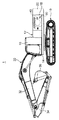
図1は、本実施形態の建設機械1の一例としての油圧ショベルを示している。建設機械1は、左走行クローラ及び右走行クローラを有する下部走行体10と、下部走行体10上に旋回可能に設けられた上部旋回体12と、上部旋回体12に対して起伏可能に当該上部旋回体12に設けられた作業アタッチメント30と、上部旋回体12に設けられたエンジン40と、冷却対象物(ラジエータやオイルクーラ等)を冷却する冷却装置50と、を備えている。
FIG. 1 shows a hydraulic excavator as an example of the
上部旋回体12は、下部走行体10上に設置されたアッパーフレーム14と、アッパーフレーム14上に配置されたキャブ室16と、機械室18と、カウンターウエイト20と、を有する。キャブ室16は、アッパーフレーム14上の前方(図1の左側)に配置されている。機械室18は、キャブ室16の後方に配置されている。この機械室18内に、エンジン40及び冷却装置50が配置されている。カウンターウエイト20は、機械室18の後方に配置されている。
The
作業アタッチメント30は、アッパーフレーム14に対して起伏可能なブーム32と、ブーム32の先端部に連結されたアーム34と、アーム34の先端部に揺動可能に取り付けられたバケット36と、を有する。
The
エンジン40は、回転する出力軸42を有している。このエンジン40は、機械室18内においてマウント43を介してアッパーフレーム14上に配置されている。
The
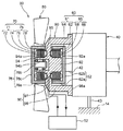
冷却装置50は、図2に示されるように、エンジン40に接続された発電機60と、発電機60から電力の供給を受けることによって回転駆動する電動機70と、電動機70に接続されており当該電動機70の回転に伴って回転することによって冷却対象物に冷却風を送るファン80と、発電機60、電動機70及びファン80を支持する支持体90と、を備えている。
As shown in FIG. 2, the
発電機60は、出力軸42に接続されており、当該出力軸42の回転に伴って電力を生成する。具体的に、発電機60は、第一ロータ61と、第一ステータ65と、を有する。本実施形態では、発電機60は、いわゆるアウターロータ型(第一ステータ65の径方向について当該第一ステータ65の外側において第一ロータ61が回転する構造)に構成されている。
The
第一ロータ61は、第一ロータ本体62と、複数の第一磁石64と、を有している。第一ロータ本体62は、複数の第一磁石64を保持する円筒状の第一円筒部62aと、出力軸42の回転を第一円筒部62aに伝達するための伝達板62bと、を有する。
The
第一円筒部62aは、第一ステータ65の外径よりも大きな内径を有している。この第一円筒部62aは、当該第一円筒部62aの内周面に周方向に沿って複数の第一磁石64が間欠的に並ぶように複数の第一磁石64を保持している。
The first
伝達板62bは、円板状であり、その外縁が第一円筒部62aのうちエンジン40側の端部に接続されている。伝達板62bは、当該伝達板62bの中心が出力軸42の中心軸の延長線上に位置するように出力軸42に接続されている。
The
第一ステータ65は、第一ステータコア66と、第一ステータコア66に巻回された第一巻線68と、を有する。
The
第一ステータコア66は、第一円筒部62aの内径よりも小さな外径を有している。第一ステータコア66は、第一円筒部62aの内側に配置される。
The
電動機70は、第一ステータ65から電力の供給を受ける第二ステータ71と、第二ステータ71に対して相対回転する第二ロータ75と、を有する。本実施形態では、電動機70もアウターロータ型に構成されている。
The
第二ステータ71は、第二ステータコア72と、第二ステータコア72に巻回された第二巻線74と、を有する。第二巻線74は、整流回路52を介して第一巻線68に接続されている。このため、第二巻線74には、発電機60で生成された電力が整流回路52を介して供給される。
The
第二ロータ75は、第二ロータ本体76と、複数の第二磁石78と、を有する。
The
第二ロータ本体76は、複数の第二磁石78を保持する円筒状の第二円筒部76aと、第二円筒部76aの内径よりも小さな外径を有する第二シャフト76bと、第二円筒部76aと第二シャフト76bとを接続するシャフト保持部76cと、を有する。
The
第二円筒部76aは、第二ステータ71の外径よりも大きな内径を有する。この第二円筒部76aは、当該第二円筒部76aの内周面に周方向に沿って複数の第二磁石78が間欠的に並ぶように複数の第二磁石78を保持している。
The second
第二シャフト76bは、第二円筒部76aの中心軸に沿って延びる形状を有する。本実施形態では、第二シャフト76bは、第二ステータ71の内径よりも小さな外径を有するとともに、第二円筒部76aの径方向に当該第二円筒部76aと重なるようにシャフト保持部76cから延びる形状を有している。
The
シャフト保持部76cは、円板状に形成されている。シャフト保持部76cは、その外縁が第二円筒部76aの一方側(図2の左側)の端部に接続されている。図3に示されるように、シャフト保持部76cには、当該シャフト保持部76cの回転時に第二ステータ71に冷却風を送ることが可能な形状のフィン76dが形成されている。なお、図3では、第二シャフト76bは省略されている。
The
ファン80は、第二ロータ75の第二円筒部76aの外周面に接続されている。ファン80は、第二ロータ75の回転に伴って回転することにより、冷却対象物に冷却風を送る。
The
支持体90は、ファン80、電動機70及び第一ステータ65のエンジン40に対する相対位置を確定しつつこれらをまとめて一体的に支持する部材である。支持体90は、ファン80、電動機70及び発電機60の第一ステータ65を支持した状態でエンジン40に固定されている。具体的に、支持体90は、第一ステータ65を支持する第一ステータ支持部92と、第二ステータ71を支持する第二ステータ支持部94と、第一ステータ支持部92及び第二ステータ支持部94をエンジン40に接続する接続部96と、を有する。本実施形態では、支持体90は、熱伝導性の高い金属(アルミニウム等)で形成されている。
The
第一ステータ支持部92は、第一ステータ65を当該第一ステータ65の径方向の内側から支持している。具体的に、第一ステータ支持部92は、円柱状に形成されており、第一ステータコア66に内側から嵌合している。換言すれば、第一ステータ支持部92は、当該第一ステータ支持部92の外周面92aと第一ステータコア66の内周面とが全周にわたって接触する状態で第一ステータ65を支持している。第一ステータ支持部92は、第一ステータ65と第一円筒部62aとが当該第一円筒部62aの径方向に対向するように第一ステータ65を支持する。また、第一ステータ支持部92は、絶縁性及び高い熱伝導性を有する薄膜の部材95を介して第一巻線68が接続部96に押し当てられるように第一ステータ65を支持する。
The first
第二ステータ支持部94は、円環状に形成されており、第一ステータ支持部92と一体的につながっている。具体的に、第二ステータ支持部94は、その中心軸が第一ステータ支持部92の中心軸の延長線上に位置するように第一ステータ支持部92からエンジン40と反対側に向かって延びる形状を有する。第二ステータ支持部94は、第二ステータコア72に内側から嵌合している。換言すれば、第二ステータ支持部94は、当該第二ステータ支持部94の外周面94aと第二ステータコア72の内周面とが全周にわたって接触する状態で第二ステータ71を支持している。第二ステータ支持部94は、第二ステータ71と第二円筒部76aとが当該第二円筒部76aの径方向に対向するように第二ステータ71を支持する。第二ステータ支持部94は、第二ステータ71の中心軸が第一ステータ65の中心軸の延長線上に位置するように当該第二ステータ71を支持する。また、第二ステータ支持部94は、絶縁性及び高い熱伝導率を有する薄膜の部材95を介して第二巻線74が接続部96に押し当てられるように第二ステータ71を支持する。
The second
第二ステータ支持部94の内側には、軸受を介して第二シャフト76bが支持されている。つまり、第二ステータ支持部94の内周面94bが、第二ロータ75を支持する「第二ロータ支持部」を構成する。第二ステータ支持部94は、出力軸42から離間した位置に第二ロータ75(第二シャフト76b)を支持する。第二ステータ支持部94は、第二シャフト76bの中心軸が第一ロータ61の中心軸(出力軸42)の延長線上に位置するように当該第二シャフト76bを支持する。
A
接続部96は、第一ステータ支持部92の中心軸が出力軸42の中心軸の延長線上に位置する姿勢で第一ステータ支持部92及び第二ステータ支持部94をエンジン40に接続する形状を有する。具体的に、接続部96は、第一ステータ支持部92及び第二ステータ支持部94の外周面から径方向の外側に向かって円板状に張り出す張出部97と、張出部97の外縁とエンジン40の外側面とを連結する連結部98と、を有する。
The
連結部98は、第一ステータ支持部92及び第二ステータ支持部94の中心軸と平行な方向に延びる円筒状に形成されている。連結部98の内径は、第一円筒部62aの外径よりも大きく設定されている。連結部98の開口側の端部98aは、エンジン40の外側面に固定されている。
The connecting
以上説明したように、本実施形態の建設機械1では、エンジン40の出力軸42の回転に伴って第一ロータ61が回転することにより第一巻線68に生じる電流が第二巻線74に供給されるので、第二ロータ75及びこの第二ロータ75に接続されたファン80が回転する。ここで、第二ロータ75は、エンジン40の出力軸42から離間した位置に支持されているので、ファン80の回転数をエンジン40の回転数から独立して調整可能となる。さらに、支持体90は、互いに一体的につながった第一ステータ支持部92、第二ステータ支持部94及び第二ロータ支持部(第二ステータ支持部94の内周面94b)を有するので、つまり、ファン80、電動機70及び発電機60の第一ステータ65が共通の支持体90によって一体的にまとめて支持されるので、これらが省スペースで配置される。
As described above, in the
また、上記実施形態では、電動機70は、いわゆるアウターロータ型に構成されている。具体的に、第二円筒部76a及び第二磁石78が第二ステータ71よりも当該第二ステータ71の径方向の外側で回転するように第二シャフト76bが支持体90の第二ステータ支持部94に支持されている。よって、これら第二円筒部76a及び第二磁石78が第二ステータ71よりも前記径方向の内側で回転する場合(いわゆるインナーロータ型)に比べて、特定のトルクをより小さな電流で得ることができる。このため、インナーロータ型に比べ、第二ステータ71での動力損失に起因する発熱量が抑制される。
Moreover, in the said embodiment, the
また、上記実施形態では、シャフト保持部76cにはフィン76dが形成されているので、第二ロータ75の回転時に第二ステータ71が効果的に空冷される。
In the above embodiment, since the
また、上記本実施形態では、第二円筒部76a、第二ステータ71及び第二シャフト76bが径方向に重なるように配置されるので、電動機70をよりコンパクトに配置することが可能となる。
Moreover, in the said embodiment, since the 2nd
また、本実施形態では、第二ロータ支持部は、第二ロータ75の中心軸が第一ロータ61の中心軸の延長線上に位置するように当該第二ロータ75を支持し、第二ステータ支持部94は、第二ステータ71の中心軸が第一ステータ65の中心軸の延長線上に位置するように当該第二ステータ71を支持している。よって、発電機60及び電動機70が共通の中心軸(エンジン40の出力軸42の延長線)に沿って並ぶので、これらがよりコンパクトに配置される。
In the present embodiment, the second rotor support portion supports the
さらに、上記実施形態では、支持体90は、第一ステータ65の中心軸が第一ロータ61の中心軸に一致する姿勢でエンジン40に固定されている。よって、エンジン40の出力軸42に接続された第一ロータ61と支持体90に支持されている第一ステータ65との相対位置が確定する。よって、エンジン40に起振力が作用した場合等における第一ロータ61と第一ステータ65との接触が抑制される。
Further, in the above embodiment, the
そして、上記実施形態では、支持体90が熱伝導性の高い金属により形成されており、第一巻線68及び第二巻線74は、絶縁性及び高い熱伝導率を有する薄膜の部材95を介して支持体90の張出部97に押し当てられている。よって、第一ステータ65及び第二ステータ71で生じる熱は、支持体90を介してエンジン40に伝達するので、第一ステータ65及び第二ステータ71が効果的に冷却される。
In the above embodiment, the
なお、上記実施形態では、第二シャフト76bが第二ステータ支持部94の内周面94bに支持される例が示されたが、第二シャフト76bの支持構造は、これに限られない。例えば、図4に示されるように、第一ステータ支持部92は、第二ステータ支持部94の内径と同じ内径の内周面92bを有する円筒状に形成され、第二シャフト76bは、第二ステータ支持部94の内側から第一ステータ支持部92の内側に至る長さに設定されるとともにこれらの内周面94b,92bに軸受を介して支持されてもよい。このようにすれば、軸受間距離を長くすることができるので、ファン80に生じる振動が抑制される。
In the above embodiment, the example in which the
(第二実施形態)
本発明の第二実施形態について、図5を参照しながら説明する。なお、この第二実施形態では、第一実施形態と異なる部分についてのみ説明を行い、第一実施形態と同じ構造、作用及び効果の説明は省略する。
(Second embodiment)
A second embodiment of the present invention will be described with reference to FIG. In the second embodiment, only the parts different from the first embodiment will be described, and the description of the same structure, operation, and effect as in the first embodiment will be omitted.
本実施形態では、発電機60及び第一ステータ65を支持する第一ステータ支持部92の構造が第一実施形態のそれと相違している。第一実施形態の発電機60は、アウターロータ型に構成されたが、本実施形態の発電機60は、インナーロータ型に構成されている。具体的に、本実施形態の第一ロータ本体62は、出力軸42に接続されるとともに、円柱状に形成されている。
In the present embodiment, the structure of the first
複数の第一磁石64は、第一ロータ本体62の周囲に周方向に沿って間欠的に並ぶように固定されている。
The plurality of
第一ステータコア66は、第一ロータ61の外径よりも大きな内径を有する円筒状に形成されている。第一ステータコア66は、その外周面が連結部98の内周面98bに全周にわたって接触するように連結部98に固定されている。つまり、本実施形態では、連結部98の内周面98bが「第一ステータ支持部」を構成する。
The
以上のように、本実施形態においても、ファン80の回転数をエンジン40の回転数から独立して調整することが可能となり、さらに、ファン80、電動機70及び発電機60の第一ステータ65を省スペースで配置することが可能となる。
As described above, also in this embodiment, the rotational speed of the
また、本実施形態では、第一ステータコア66の外周面と連結部98の内周面98bとが接触するので、第一実施形態のように第一ステータコア66の内周面と第一ステータ支持部92の外周面92aとが接触する場合に比べて第一ステータコア66と支持体90との接触面積が大きくなる。よって、第二実施形態では、第一実施形態に比べて第一ステータ65の放熱性が高まる。
In this embodiment, since the outer peripheral surface of the
なお、今回開示された実施形態は、すべての点で例示であって制限的なものではないと考えられるべきである。本発明の範囲は、上記した実施形態の説明ではなく特許請求の範囲によって示され、さらに特許請求の範囲と均等の意味および範囲内でのすべての変更が含まれる。 The embodiment disclosed this time should be considered as illustrative in all points and not restrictive. The scope of the present invention is shown not by the above description of the embodiments but by the scope of claims for patent, and further includes all modifications within the meaning and scope equivalent to the scope of claims for patent.
例えば、上記実施形態では、電動機70がアウターロータ型に構成された例が示されたが、電動機70は、インナーロータ型に構成されてもよい。この場合、複数の第二磁石78は、第二シャフト76bの周囲に周方向に沿って間欠的に並ぶように固定される。
For example, in the above-described embodiment, an example in which the
1 建設機械(油圧ショベル)
10 下部走行体
12 上部旋回体
14 アッパーフレーム
30 作業アタッチメント
40 エンジン
42 出力軸
50 冷却装置
60 発電機
61 第一ロータ
62 第一ロータ本体
64 複数の第一磁石
65 第一ステータ
66 第一ステータコア
68 第一巻線
70 電動機
71 第二ステータ
72 第二ステータコア
74 第二巻線
75 第二ロータ
76 第二ロータ本体
76a 第二円筒部
76b 第二シャフト
76c シャフト保持部
76d フィン
78 複数の第二磁石
80 ファン
90 支持体
92 第一ステータ支持部
92a 第一ステータ支持部の外周面
94 第二ステータ支持部
94a 第二ステータ支持部の外周面
94b 第二ステータ支持部の内周面(第二ロータ支持部)
96 接続部
98 連結部
98b 連結部の内周面(第一ステータ支持部)
1 Construction machine (hydraulic excavator)
DESCRIPTION OF
96
Claims (6)
回転する出力軸を有するエンジンと、
前記出力軸に接続されており、当該出力軸の回転に伴って電力を生成する発電機と、
前記発電機で生成された電力の供給を受けることによって回転駆動する電動機と、
前記電動機に接続されており、当該電動機の回転に伴って回転することにより冷却対象物に対して冷却風を送るファンと、
前記発電機、前記電動機及び前記ファンの前記エンジンに対する相対位置を確定しつつこれらを支持する支持体と、を備え、
前記発電機は、前記エンジンの出力軸に接続されており前記出力軸の中心軸の延長線周りに間欠的に並ぶ複数の第一磁石を有する第一ロータと、前記第一ロータに対して相対回転する第一ステータと、を有し、
前記電動機は、前記第一ステータから電流の供給を受ける第二ステータと、前記第二ステータに対して相対回転可能であるとともに前記第二ステータの中心軸周りに間欠的に並ぶ複数の第二磁石を有し、かつ前記ファンに接続された第二ロータと、を有し、
前記支持体は、前記第一ステータと前記第一ロータとが当該第一ロータの径方向に対向するように前記第一ステータを支持する第一ステータ支持部と、前記第一ステータ支持部と一体的につながっておりかつ前記出力軸から離間した位置に前記第二ロータを支持する第二ロータ支持部と、前記第二ロータ支持部と一体的につながっておりかつ前記第二ステータと前記第二ロータとが当該第二ロータの径方向に互いに対向するように前記第二ステータを支持する第二ステータ支持部と、を有する、建設機械。 A construction machine,
An engine having a rotating output shaft;
A generator that is connected to the output shaft and generates electric power as the output shaft rotates;
An electric motor that rotates by receiving supply of electric power generated by the generator;
A fan that is connected to the electric motor and sends cooling air to an object to be cooled by rotating with the rotation of the electric motor;
A support that supports the generator, the electric motor, and the fan while determining the relative position of the fan to the engine, and
The generator is connected to an output shaft of the engine and has a first rotor having a plurality of first magnets intermittently arranged around an extension line of a central axis of the output shaft, and a relative to the first rotor A rotating first stator,
The electric motor includes a second stator that receives a current supply from the first stator, and a plurality of second magnets that are rotatable relative to the second stator and are intermittently arranged around a central axis of the second stator. And a second rotor connected to the fan,
The support includes a first stator support portion that supports the first stator so that the first stator and the first rotor face each other in the radial direction of the first rotor, and the first stator support portion. And a second rotor support portion that supports the second rotor at a position spaced from the output shaft, and is integrally connected to the second rotor support portion and the second stator and the second A construction machine comprising: a second stator support portion that supports the second stator so that the rotor faces each other in the radial direction of the second rotor.
前記第二ロータは、前記第二ステータの外径よりも大きな内径を有する円筒状の第二円筒部と、前記第二円筒部の中心軸に沿って延びる形状の第二シャフトと、前記第二円筒部と前記第二シャフトとを接続する第二シャフト保持部と、を有し、
前記複数の第二磁石は、前記第二円筒部の内周面に固定されており、
前記第二ロータ支持部は、前記第二シャフトを当該第二シャフトの軸回りに回転可能に支持し、
前記第二ステータ支持部は、前記第二ステータの径方向について前記第二円筒部の内側に前記第二ステータを支持する、建設機械。 The construction machine according to claim 1,
The second rotor includes a cylindrical second cylindrical portion having an inner diameter larger than an outer diameter of the second stator, a second shaft having a shape extending along a central axis of the second cylindrical portion, and the second rotor A second shaft holding portion that connects the cylindrical portion and the second shaft,
The plurality of second magnets are fixed to the inner peripheral surface of the second cylindrical portion,
The second rotor support portion supports the second shaft so as to be rotatable around the axis of the second shaft,
The second stator support portion is a construction machine that supports the second stator inside the second cylindrical portion in a radial direction of the second stator.
前記シャフト保持部には、当該シャフト保持部の回転時に前記第二ステータに冷却風を送ることが可能な形状のフィンが形成されている、建設機械。 The construction machine according to claim 2,
A construction machine in which the shaft holding part is formed with a fin having a shape capable of sending cooling air to the second stator when the shaft holding part rotates.
前記第二シャフトは、前記第二円筒部の径方向に当該第二円筒部と重なるように前記シャフト保持部から延びる形状を有し、
前記第二ロータ支持部は、前記第二ステータの径方向について前記第二シャフトが前記第二ステータの内側に位置するように当該第二シャフトを支持する、建設機械。 In the construction machine according to claim 2 or 3,
The second shaft has a shape extending from the shaft holding portion so as to overlap the second cylindrical portion in the radial direction of the second cylindrical portion,
The second rotor support portion is a construction machine that supports the second shaft such that the second shaft is positioned inside the second stator in the radial direction of the second stator.
前記第二ロータ支持部は、前記第二ロータの中心軸が第一ロータの中心軸の延長線上に位置するように当該第二ロータを支持し、
第二ステータ支持部は、前記第二ステータの中心軸が第一ステータの中心軸の延長線上に位置するように当該第二ステータを支持する、建設機械。 The construction machine according to any one of claims 1 to 4,
The second rotor support portion supports the second rotor such that the central axis of the second rotor is located on an extension line of the central axis of the first rotor,
The second stator support portion is a construction machine that supports the second stator so that the central axis of the second stator is positioned on an extension line of the central axis of the first stator.
前記支持体は、前記第一ステータの中心軸が前記第一ロータの中心軸に一致する姿勢で前記エンジンに固定されている、建設機械。
In the construction machine according to any one of claims 1 to 5,
The said support body is a construction machine fixed to the said engine with the attitude | position in which the center axis | shaft of a said 1st stator corresponds with the center axis | shaft of a said 1st rotor.
Priority Applications (1)
| Application Number | Priority Date | Filing Date | Title |
|---|---|---|---|
| JP2014125463A JP2016005398A (en) | 2014-06-18 | 2014-06-18 | Construction machine |
Applications Claiming Priority (1)
| Application Number | Priority Date | Filing Date | Title |
|---|---|---|---|
| JP2014125463A JP2016005398A (en) | 2014-06-18 | 2014-06-18 | Construction machine |
Publications (1)
| Publication Number | Publication Date |
|---|---|
| JP2016005398A true JP2016005398A (en) | 2016-01-12 |
Family
ID=55224316
Family Applications (1)
| Application Number | Title | Priority Date | Filing Date |
|---|---|---|---|
| JP2014125463A Pending JP2016005398A (en) | 2014-06-18 | 2014-06-18 | Construction machine |
Country Status (1)
| Country | Link |
|---|---|
| JP (1) | JP2016005398A (en) |
Cited By (2)
| Publication number | Priority date | Publication date | Assignee | Title |
|---|---|---|---|---|
| CN114809172A (en) * | 2022-03-23 | 2022-07-29 | 福建万润新能源科技有限公司 | Digging machine |
| US11549427B2 (en) | 2020-04-17 | 2023-01-10 | Caterpillar Inc. | Engine and fan system having an electric motor |
-
2014
- 2014-06-18 JP JP2014125463A patent/JP2016005398A/en active Pending
Cited By (3)
| Publication number | Priority date | Publication date | Assignee | Title |
|---|---|---|---|---|
| US11549427B2 (en) | 2020-04-17 | 2023-01-10 | Caterpillar Inc. | Engine and fan system having an electric motor |
| CN114809172A (en) * | 2022-03-23 | 2022-07-29 | 福建万润新能源科技有限公司 | Digging machine |
| CN114809172B (en) * | 2022-03-23 | 2023-10-27 | 福建万润新能源科技有限公司 | Excavator |
Similar Documents
| Publication | Publication Date | Title |
|---|---|---|
| JP2012255409A5 (en) | ||
| KR20150026882A (en) | Axial gap type generator | |
| JP2012147513A (en) | Magnetic gear and rotating machine having the same | |
| JP2007336721A (en) | Cooling motor | |
| JP2020043693A (en) | Outer rotor type rotary electric machine and winch | |
| JP2016005398A (en) | Construction machine | |
| US20140125166A1 (en) | Rotating electrical machine | |
| WO2021036082A1 (en) | Permanent magnet motor with heat dissipation structure | |
| JP6696231B2 (en) | Hoisting machine | |
| JP6540023B2 (en) | fan | |
| JP6624223B2 (en) | Rotating electric machine | |
| JP2019083638A (en) | Outer rotation type rotary electric machine and hoist for elevators | |
| JP2011223805A (en) | Rotary device | |
| JP2016513548A (en) | Blender motor housing | |
| JP2018026920A (en) | motor | |
| JP2017200354A (en) | Brushless rotary electric machine | |
| JP5723855B2 (en) | Rotating electric machine | |
| JP2010269440A (en) | Built-in motor cooling unit | |
| JP2017017787A (en) | motor | |
| JP2016111909A5 (en) | ||
| JP2020112114A5 (en) | ||
| JP5542984B1 (en) | AC generator for vehicles | |
| JP2004138133A (en) | Bearing with power generating function | |
| KR102634114B1 (en) | Rotating device | |
| JP2019032947A5 (en) |