JP2016005118A - Oscillation circuit, oscillator, electronic apparatus, and mobile - Google Patents
Oscillation circuit, oscillator, electronic apparatus, and mobile Download PDFInfo
- Publication number
- JP2016005118A JP2016005118A JP2014124061A JP2014124061A JP2016005118A JP 2016005118 A JP2016005118 A JP 2016005118A JP 2014124061 A JP2014124061 A JP 2014124061A JP 2014124061 A JP2014124061 A JP 2014124061A JP 2016005118 A JP2016005118 A JP 2016005118A
- Authority
- JP
- Japan
- Prior art keywords
- terminal
- voltage
- oscillation circuit
- circuit
- oscillation
- Prior art date
- Legal status (The legal status is an assumption and is not a legal conclusion. Google has not performed a legal analysis and makes no representation as to the accuracy of the status listed.)
- Pending
Links
- 230000010355 oscillation Effects 0.000 title claims abstract description 269
- 238000005056 compaction Methods 0.000 abstract 1
- 239000000872 buffer Substances 0.000 description 25
- 230000006870 function Effects 0.000 description 10
- 239000000758 substrate Substances 0.000 description 9
- 238000010586 diagram Methods 0.000 description 8
- 239000000463 material Substances 0.000 description 8
- 238000012986 modification Methods 0.000 description 7
- 230000004048 modification Effects 0.000 description 7
- 230000006866 deterioration Effects 0.000 description 6
- 230000000694 effects Effects 0.000 description 6
- PXHVJJICTQNCMI-UHFFFAOYSA-N Nickel Chemical compound [Ni] PXHVJJICTQNCMI-UHFFFAOYSA-N 0.000 description 5
- 238000005219 brazing Methods 0.000 description 5
- 239000003990 capacitor Substances 0.000 description 5
- 238000003384 imaging method Methods 0.000 description 5
- 239000000919 ceramic Substances 0.000 description 4
- 238000004891 communication Methods 0.000 description 4
- 239000010931 gold Substances 0.000 description 4
- 229910052709 silver Inorganic materials 0.000 description 4
- 239000004332 silver Substances 0.000 description 4
- 238000003466 welding Methods 0.000 description 4
- KDLHZDBZIXYQEI-UHFFFAOYSA-N Palladium Chemical compound [Pd] KDLHZDBZIXYQEI-UHFFFAOYSA-N 0.000 description 3
- BQCADISMDOOEFD-UHFFFAOYSA-N Silver Chemical compound [Ag] BQCADISMDOOEFD-UHFFFAOYSA-N 0.000 description 3
- 238000000034 method Methods 0.000 description 3
- IJGRMHOSHXDMSA-UHFFFAOYSA-N Atomic nitrogen Chemical compound N#N IJGRMHOSHXDMSA-UHFFFAOYSA-N 0.000 description 2
- 230000001413 cellular effect Effects 0.000 description 2
- 239000013078 crystal Substances 0.000 description 2
- 230000005669 field effect Effects 0.000 description 2
- PCHJSUWPFVWCPO-UHFFFAOYSA-N gold Chemical compound [Au] PCHJSUWPFVWCPO-UHFFFAOYSA-N 0.000 description 2
- 229910052737 gold Inorganic materials 0.000 description 2
- 229910000833 kovar Inorganic materials 0.000 description 2
- 238000012544 monitoring process Methods 0.000 description 2
- 230000003287 optical effect Effects 0.000 description 2
- 238000012545 processing Methods 0.000 description 2
- 238000007789 sealing Methods 0.000 description 2
- WFKWXMTUELFFGS-UHFFFAOYSA-N tungsten Chemical compound [W] WFKWXMTUELFFGS-UHFFFAOYSA-N 0.000 description 2
- 229910052721 tungsten Inorganic materials 0.000 description 2
- 239000010937 tungsten Substances 0.000 description 2
- 241000251468 Actinopterygii Species 0.000 description 1
- 229910001316 Ag alloy Inorganic materials 0.000 description 1
- 229910000531 Co alloy Inorganic materials 0.000 description 1
- 229910000640 Fe alloy Inorganic materials 0.000 description 1
- WQZGKKKJIJFFOK-GASJEMHNSA-N Glucose Natural products OC[C@H]1OC(O)[C@H](O)[C@@H](O)[C@@H]1O WQZGKKKJIJFFOK-GASJEMHNSA-N 0.000 description 1
- 229910000990 Ni alloy Inorganic materials 0.000 description 1
- 229910001252 Pd alloy Inorganic materials 0.000 description 1
- 239000000853 adhesive Substances 0.000 description 1
- 230000001070 adhesive effect Effects 0.000 description 1
- 229910045601 alloy Inorganic materials 0.000 description 1
- 239000000956 alloy Substances 0.000 description 1
- 230000008901 benefit Effects 0.000 description 1
- 239000011230 binding agent Substances 0.000 description 1
- 239000008280 blood Substances 0.000 description 1
- 210000004369 blood Anatomy 0.000 description 1
- 230000036772 blood pressure Effects 0.000 description 1
- 230000008859 change Effects 0.000 description 1
- 239000010941 cobalt Substances 0.000 description 1
- GUTLYIVDDKVIGB-UHFFFAOYSA-N cobalt atom Chemical compound [Co] GUTLYIVDDKVIGB-UHFFFAOYSA-N 0.000 description 1
- 239000004020 conductor Substances 0.000 description 1
- 238000010304 firing Methods 0.000 description 1
- 239000011521 glass Substances 0.000 description 1
- 239000008103 glucose Substances 0.000 description 1
- 230000006872 improvement Effects 0.000 description 1
- 239000011261 inert gas Substances 0.000 description 1
- 238000010030 laminating Methods 0.000 description 1
- 238000005259 measurement Methods 0.000 description 1
- 238000002844 melting Methods 0.000 description 1
- 230000008018 melting Effects 0.000 description 1
- 229910052751 metal Inorganic materials 0.000 description 1
- 239000002184 metal Substances 0.000 description 1
- 229910044991 metal oxide Inorganic materials 0.000 description 1
- 150000004706 metal oxides Chemical class 0.000 description 1
- 229910052759 nickel Inorganic materials 0.000 description 1
- 229910052757 nitrogen Inorganic materials 0.000 description 1
- 229910052763 palladium Inorganic materials 0.000 description 1
- 230000000149 penetrating effect Effects 0.000 description 1
- 239000000843 powder Substances 0.000 description 1
- 239000011347 resin Substances 0.000 description 1
- 229920005989 resin Polymers 0.000 description 1
- -1 silver halide Chemical class 0.000 description 1
- 238000005245 sintering Methods 0.000 description 1
- 229910000679 solder Inorganic materials 0.000 description 1
Images


Classifications
-
- H—ELECTRICITY
- H03—ELECTRONIC CIRCUITRY
- H03B—GENERATION OF OSCILLATIONS, DIRECTLY OR BY FREQUENCY-CHANGING, BY CIRCUITS EMPLOYING ACTIVE ELEMENTS WHICH OPERATE IN A NON-SWITCHING MANNER; GENERATION OF NOISE BY SUCH CIRCUITS
- H03B5/00—Generation of oscillations using amplifier with regenerative feedback from output to input
- H03B5/30—Generation of oscillations using amplifier with regenerative feedback from output to input with frequency-determining element being electromechanical resonator
- H03B5/32—Generation of oscillations using amplifier with regenerative feedback from output to input with frequency-determining element being electromechanical resonator being a piezoelectric resonator
- H03B5/36—Generation of oscillations using amplifier with regenerative feedback from output to input with frequency-determining element being electromechanical resonator being a piezoelectric resonator active element in amplifier being semiconductor device
- H03B5/366—Generation of oscillations using amplifier with regenerative feedback from output to input with frequency-determining element being electromechanical resonator being a piezoelectric resonator active element in amplifier being semiconductor device and comprising means for varying the frequency by a variable voltage or current
- H03B5/368—Generation of oscillations using amplifier with regenerative feedback from output to input with frequency-determining element being electromechanical resonator being a piezoelectric resonator active element in amplifier being semiconductor device and comprising means for varying the frequency by a variable voltage or current the means being voltage variable capacitance diodes
-
- H—ELECTRICITY
- H03—ELECTRONIC CIRCUITRY
- H03B—GENERATION OF OSCILLATIONS, DIRECTLY OR BY FREQUENCY-CHANGING, BY CIRCUITS EMPLOYING ACTIVE ELEMENTS WHICH OPERATE IN A NON-SWITCHING MANNER; GENERATION OF NOISE BY SUCH CIRCUITS
- H03B5/00—Generation of oscillations using amplifier with regenerative feedback from output to input
- H03B5/02—Details
- H03B5/04—Modifications of generator to compensate for variations in physical values, e.g. power supply, load, temperature
-
- H—ELECTRICITY
- H03—ELECTRONIC CIRCUITRY
- H03B—GENERATION OF OSCILLATIONS, DIRECTLY OR BY FREQUENCY-CHANGING, BY CIRCUITS EMPLOYING ACTIVE ELEMENTS WHICH OPERATE IN A NON-SWITCHING MANNER; GENERATION OF NOISE BY SUCH CIRCUITS
- H03B5/00—Generation of oscillations using amplifier with regenerative feedback from output to input
- H03B5/30—Generation of oscillations using amplifier with regenerative feedback from output to input with frequency-determining element being electromechanical resonator
- H03B5/32—Generation of oscillations using amplifier with regenerative feedback from output to input with frequency-determining element being electromechanical resonator being a piezoelectric resonator
- H03B5/36—Generation of oscillations using amplifier with regenerative feedback from output to input with frequency-determining element being electromechanical resonator being a piezoelectric resonator active element in amplifier being semiconductor device
- H03B5/362—Generation of oscillations using amplifier with regenerative feedback from output to input with frequency-determining element being electromechanical resonator being a piezoelectric resonator active element in amplifier being semiconductor device the amplifier being a single transistor
-
- H—ELECTRICITY
- H03—ELECTRONIC CIRCUITRY
- H03L—AUTOMATIC CONTROL, STARTING, SYNCHRONISATION, OR STABILISATION OF GENERATORS OF ELECTRONIC OSCILLATIONS OR PULSES
- H03L1/00—Stabilisation of generator output against variations of physical values, e.g. power supply
-
- H—ELECTRICITY
- H03—ELECTRONIC CIRCUITRY
- H03B—GENERATION OF OSCILLATIONS, DIRECTLY OR BY FREQUENCY-CHANGING, BY CIRCUITS EMPLOYING ACTIVE ELEMENTS WHICH OPERATE IN A NON-SWITCHING MANNER; GENERATION OF NOISE BY SUCH CIRCUITS
- H03B2201/00—Aspects of oscillators relating to varying the frequency of the oscillations
- H03B2201/03—Varying beside the frequency also another parameter of the oscillator in dependence on the frequency
- H03B2201/031—Varying beside the frequency also another parameter of the oscillator in dependence on the frequency the parameter being the amplitude of a signal, e.g. maintaining a constant output amplitude over the frequency range
Abstract
Description
本発明は、発振回路、発振器、電子機器、および移動体に関する。 The present invention relates to an oscillation circuit, an oscillator, an electronic device, and a moving object.
従来から、通信機器分野の安定な周波数制御電子部品として、水晶などの圧電体から形成された振動片と、所望の周波数の信号を出力する発振回路と、をパッケージ内に備え、出力する周波数を外部から入力された制御電圧によって、可変または調整する発振器が用いられていた。この発振器のパッケージには、発振回路を駆動させる電源端子(VCC)、グランド端子(GND)、信号出力端子(RFOUT)、周波数制御電圧入力端子(VCONT)を含む多くの外部接続端子が設けられていた。しかし、パッケージに設ける外部接続端子が多いと、発振器の小型化が困難になるため、一つの外部接続端子に複数の機能を持たせた発振器が提案されている。例えば、特許文献1に記載されているように、デジタル温度補償データを記憶する内部記憶装置を備えたデジタル制御温度補償基準発振器において、電源端子が、内部記憶装置への書き込みに用いられるクロック信号入力端子の機能を兼ね備えることにより、パッケージに設ける外部接続端子の数を減らして発振器の小型化を図った構成が開示されている。
Conventionally, as a stable frequency control electronic component in the field of communication equipment, a resonator element formed of a piezoelectric body such as crystal and an oscillation circuit that outputs a signal of a desired frequency are provided in a package, and the frequency to be output is provided. An oscillator that can be adjusted or adjusted by a control voltage input from the outside has been used. This oscillator package is provided with many external connection terminals including a power supply terminal (VCC), a ground terminal (GND), a signal output terminal (RFOUT), and a frequency control voltage input terminal (VCONT) for driving the oscillation circuit. It was. However, if there are many external connection terminals provided in the package, it is difficult to reduce the size of the oscillator. Therefore, an oscillator in which a single external connection terminal has a plurality of functions has been proposed. For example, as described in
特許文献1に記載されている構成の発振器によれば、外部接続端子の数を減らせるので発振器の小型を図ることができるが、電源端子には、発振用回路を駆動させるための直流電圧に、周波数信号であるクロック信号を重畳させて供給する必要がある。しかしながら、このクロック信号が発振用回路の電源端子に供給されると、発振用回路にはノイズとして入力されるため、発振器から出力される発振信号の周波数精度が低下してしまう恐れがあった。したがって、外部接続端子数を減らすことにより生じる周波数精度の低下を抑えて、小型化を図ることが可能な発振回路(発振器)を実現することが難しかった。
According to the oscillator having the configuration described in
本発明は、上述の課題の少なくとも一部を解決するためになされたものであり、以下の形態または適用例として実現することが可能である。 SUMMARY An advantage of some aspects of the invention is to solve at least a part of the problems described above, and the invention can be implemented as the following forms or application examples.
[適用例1]本適用例に係る発振回路は、発振用回路と、前記発振用回路に接続されている信号調整回路と、を備え、前記発振用回路および前記信号調整回路には、電圧値を可変させることができる直流電圧に基づく入力電圧が入力され、前記発振用回路は、振動片を発振させると共に、第1発振信号を出力し、前記第1発振信号の周波数は、前記信号調整回路から出力される電圧値に応じて調整されること、を特徴とする。 Application Example 1 An oscillation circuit according to this application example includes an oscillation circuit and a signal adjustment circuit connected to the oscillation circuit, and the oscillation circuit and the signal adjustment circuit include a voltage value. The oscillation circuit oscillates the vibration piece and outputs a first oscillation signal, and the frequency of the first oscillation signal is determined by the signal adjustment circuit. It adjusts according to the voltage value output from.
本適用例によれば、発振回路は、発振用回路と、信号調整回路とを含んでいる。従来、発振回路は、発振用回路の駆動用電源として印加される直流電圧と、第1発振信号の周波数を調整するために信号調整回路に印加される電圧値を可変することができる直流電圧と、の2系統の電源を必要としていた。しかし、本適用例の発振回路では、発振用回路の直流電圧に、信号調整回路に必要な電圧値の可変幅を有する直流電圧を重畳させた1系統の電圧値を可変させることができる直流電圧に基づく入力電圧が、発振用回路と信号調整回路とに入力されている。換言すると、発振用回路と信号調整回路とに、外部から供給する接地電圧以外の直流電圧を1系統にすることができるので、発振回路を収納する容器の外部接続端子数を減らすことができる。この重畳された入力電圧は、周波数信号を含んでいないため、第1発振信号に対するノイズとなる可能性が低減し、外部接続端子数を減らすことにより生じる第1発振信号の周波数精度の低下を抑えることができる。したがって、発振用回路から出力される第1発振信号の周波数精度の低下を抑え、発振器の小型化を図ることが可能な発振回路を提供することができる。 According to this application example, the oscillation circuit includes an oscillation circuit and a signal adjustment circuit. Conventionally, an oscillation circuit has a DC voltage applied as a driving power source for an oscillation circuit, and a DC voltage that can vary a voltage value applied to a signal adjustment circuit in order to adjust the frequency of the first oscillation signal. , Two power sources were required. However, in the oscillation circuit of this application example, a DC voltage that can vary a voltage value of one system in which a DC voltage having a variable width of a voltage value necessary for the signal adjustment circuit is superimposed on the DC voltage of the oscillation circuit. Is input to the oscillation circuit and the signal adjustment circuit. In other words, since the DC voltage other than the ground voltage supplied from the outside can be made into one system for the oscillation circuit and the signal adjustment circuit, the number of external connection terminals of the container housing the oscillation circuit can be reduced. Since the superimposed input voltage does not include a frequency signal, the possibility of becoming noise with respect to the first oscillation signal is reduced, and a decrease in frequency accuracy of the first oscillation signal caused by reducing the number of external connection terminals is suppressed. be able to. Therefore, it is possible to provide an oscillation circuit that can suppress a decrease in frequency accuracy of the first oscillation signal output from the oscillation circuit and can reduce the size of the oscillator.
[適用例2]上記適用例に記載の発振回路は、前記発振用回路に接続されている電圧調整回路を備え、前記電圧調整回路は、前記入力電圧が入力されて前記直流電圧を所定の電圧値に変換して前記発振用回路に出力すること、が好ましい。 Application Example 2 The oscillation circuit according to the application example includes a voltage adjustment circuit connected to the oscillation circuit, and the voltage adjustment circuit receives the input voltage and converts the DC voltage to a predetermined voltage. It is preferable to convert it into a value and output it to the oscillation circuit.
本適用例によれば、発振回路は、入力電圧の電圧値が変動しても、所定の電圧値に変換して出力する電圧調整回路を備え、電圧調整回路から出力された直流電圧は、発振用回路の駆動用電源として供給されている。第1発振信号の周波数を調整するために、外部から供給される入力電圧の電圧値が変更されても、発振用回路の駆動用電源として入力される電圧調整回路から出力された直流電圧の電圧値は一定であるので、第1発振信号に対するノイズとなる可能性が低減し、第1発振信号の周波数精度の低下を抑えることができる。したがって、発振用回路から出力される第1発振信号の周波数精度の低下を抑え、発振器の小型化を図ることが可能な発振回路を提供することができる。 According to this application example, the oscillation circuit includes the voltage adjustment circuit that converts the output voltage into a predetermined voltage value even if the voltage value of the input voltage fluctuates, and the DC voltage output from the voltage adjustment circuit oscillates. It is supplied as a power source for driving the circuit. Even if the voltage value of the input voltage supplied from the outside is changed to adjust the frequency of the first oscillation signal, the voltage of the DC voltage output from the voltage adjustment circuit that is input as the driving power source of the oscillation circuit Since the value is constant, the possibility of noise with respect to the first oscillation signal is reduced, and a decrease in frequency accuracy of the first oscillation signal can be suppressed. Therefore, it is possible to provide an oscillation circuit that can suppress a decrease in frequency accuracy of the first oscillation signal output from the oscillation circuit and can reduce the size of the oscillator.
[適用例3]上記適用例に記載の発振回路において、前記発振用回路は、可変容量素子を含み、前記可変容量素子の静電容量値は、前記信号調整回路から出力される電圧値に応じて設定されること、が好ましい。 Application Example 3 In the oscillation circuit according to the application example, the oscillation circuit includes a variable capacitance element, and a capacitance value of the variable capacitance element corresponds to a voltage value output from the signal adjustment circuit. Is preferably set.
本適用例によれば、発振用回路には、信号調整回路から出力される電圧値に応じて静電容量値が設定される可変容量素子を備えている。信号調整回路に入力される入力電圧の電圧値に応じて信号調整回路から出力される直流電圧を可変容量素子に印加することで、発振用回路から出力される第1発振信号の周波数を調整することができる。 According to this application example, the oscillation circuit includes the variable capacitance element in which the capacitance value is set according to the voltage value output from the signal adjustment circuit. The frequency of the first oscillation signal output from the oscillation circuit is adjusted by applying a DC voltage output from the signal adjustment circuit to the variable capacitance element in accordance with the voltage value of the input voltage input to the signal adjustment circuit. be able to.
[適用例4]上記適用例に記載の発振回路において、前記信号調整回路は、自動周波数制御回路を含んでいること、が好ましい。 Application Example 4 In the oscillation circuit described in the application example, it is preferable that the signal adjustment circuit includes an automatic frequency control circuit.
本適用例によれば、信号調整回路には、自動周波数制御回路が含まれているので、第1発振信号の周波数を調整するために可変容量素子に印加する直流電圧を容易に生成することができる。 According to this application example, since the signal adjustment circuit includes the automatic frequency control circuit, it is possible to easily generate a DC voltage to be applied to the variable capacitance element in order to adjust the frequency of the first oscillation signal. it can.
[適用例5]本適用例に係る発振器は、前記適用例のいずれかに記載の発振回路と、振動片と、前記発振回路と前記振動片とが内包される容器と、を含み、前記容器は、平面視において、互いに対向している第1辺および第2辺と、前記第1辺および前記第2辺と交差し互いに対向している第3辺および第4辺と、前記第1辺、前記第2辺、前記第3辺のうち少なくとも一つの辺に接し、前記第3辺に沿った方向に配置されている第1端子と、前記第1辺、前記第2辺、前記第4辺のうち少なくとも一つの辺に接し、前記第4辺に沿った方向に配置されている第2端子と、前記第1端子と前記第2端子との間に設けられている第3端子と、を有し、前記第1端子は、電圧値を可変させることができる直流電圧に基づく入力電圧が印加される端子であり、前記第2端子は、接地電圧が印加される端子であり、前記第3端子は、前記発振回路から出力される第1発振信号が出力される端子であること、を特徴とする。 Application Example 5 An oscillator according to this application example includes the oscillation circuit according to any one of the application examples, a resonator element, and a container that includes the oscillation circuit and the resonator element. Is a first side and a second side facing each other in plan view, a third side and a fourth side crossing the first side and the second side and facing each other, and the first side A first terminal that contacts at least one of the second side and the third side and is disposed in a direction along the third side, the first side, the second side, and the fourth side. A second terminal in contact with at least one of the sides and disposed in a direction along the fourth side; a third terminal provided between the first terminal and the second terminal; The first terminal has an end to which an input voltage based on a DC voltage that can vary a voltage value is applied. And at the second terminal is a terminal to which a ground voltage is applied, the third terminal, it first oscillation signal outputted from said oscillator circuit is a terminal to be outputted, characterized by.
本適用例によれば、発振器は、発振回路、振動片および容器を含んでおり、発振回路は、発振用回路と、信号調整回路とを含んでいる。従来、発振回路は、発振用回路の駆動用電源としての直流電圧と、第1発振信号の周波数を調整するために信号調整回路に印加される電圧値を可変することができる直流電圧と、の2系統の電源を必要としていた。しかし、本適用例の発振回路では、発振用回路の直流電圧に、信号調整回路に必要な電圧値の可変幅を有する直流電圧を重畳させた1系統の直流電圧が、発振用回路と信号調整回路とに入力されている。換言すると、発振用回路と信号調整回路とに、外部から供給する接地電圧以外の直流電圧を1系統の電圧値を可変させることができる直流電圧に基づく入力電圧にすることができる。これにより、第1発振信号の周波数を調整することが可能な発振器を、入力電圧を印加させる第1端子と、接地電圧が印加される第2端子と、第1発振信号が出力される第3端子と、の三つの外部接続端子を備えた小型の容器で構成させることができる。また、この重畳された入力電圧は、周波数信号を含んでいないため、第1発振信号に対するノイズとなる可能性が低減し、第1発振信号の周波数精度の低下を抑えることができる。したがって、発振用回路から出力される第1発振信号の周波数精度の低下を抑えて小型化を図った発振器を提供することができる。 According to this application example, the oscillator includes an oscillation circuit, a resonator element, and a container, and the oscillation circuit includes an oscillation circuit and a signal adjustment circuit. Conventionally, an oscillation circuit includes a DC voltage as a driving power source for an oscillation circuit, and a DC voltage that can vary a voltage value applied to the signal adjustment circuit to adjust the frequency of the first oscillation signal. Two power sources were required. However, in the oscillation circuit according to this application example, a single DC voltage obtained by superimposing a DC voltage having a variable width of a voltage value necessary for the signal adjustment circuit on the DC voltage of the oscillation circuit is combined with the oscillation circuit and the signal adjustment. It is input to the circuit. In other words, the DC voltage other than the ground voltage supplied from the outside can be used as the input voltage based on the DC voltage that can vary the voltage value of one system in the oscillation circuit and the signal adjustment circuit. As a result, the oscillator capable of adjusting the frequency of the first oscillation signal includes a first terminal to which the input voltage is applied, a second terminal to which the ground voltage is applied, and a third terminal from which the first oscillation signal is output. And a small container provided with three external connection terminals. In addition, since the superimposed input voltage does not include a frequency signal, the possibility of becoming noise with respect to the first oscillation signal is reduced, and a decrease in frequency accuracy of the first oscillation signal can be suppressed. Therefore, it is possible to provide an oscillator that is miniaturized by suppressing a decrease in frequency accuracy of the first oscillation signal output from the oscillation circuit.
[適用例6]上記適用例に記載の発振器において、前記容器は、前記第1端子および前記第2端子のいずれか一方と、前記第3端子と、の間に設けられている第4端子を備え、前記第4端子からは、前記発振回路から出力される第2発振信号が出力されること、が好ましい。 Application Example 6 In the oscillator according to the application example described above, the container may include a fourth terminal provided between one of the first terminal and the second terminal and the third terminal. Preferably, the second terminal outputs the second oscillation signal output from the oscillation circuit.
本適用例によれば、発振器の容器には、第2発振信号を出力する第4端子が設けられているので、互いに極性が反対の周波数信号を出力する差動出力発振器や、2種類の異なる周波数信号を出力する2周波数出力発振器を構成することができる。 According to this application example, since the container of the oscillator is provided with the fourth terminal for outputting the second oscillation signal, the differential output oscillator for outputting the frequency signals having opposite polarities or two different types A two-frequency output oscillator that outputs a frequency signal can be configured.
[適用例7]本適用例に係る電子機器は、上記適用例1から4のいずれかに記載の発振回路を備えていることを特徴とする。 Application Example 7 An electronic apparatus according to this application example includes the oscillation circuit according to any one of Application Examples 1 to 4.
本適用例によれば、発振器の小型化を図ることができる発振回路を備えているので、小型な電子機器を提供することができる。 According to this application example, since the oscillator circuit capable of reducing the size of the oscillator is provided, a small electronic device can be provided.
[適用例8]本適用例に係る移動体は、上記適用例1から4のいずれかに記載の発振回路を備えていることを特徴とする。 Application Example 8 A moving object according to this application example includes the oscillation circuit according to any one of Application Examples 1 to 4.
本適用例によれば、発振器の小型化を図ることができる発振回路を備えているので、小型な移動体を提供することができる。 According to this application example, since the oscillation circuit capable of reducing the size of the oscillator is provided, a small movable body can be provided.
以下、本発明の実施形態について、図面を参照して説明する。なお、以下の各図においては、各層や各部材を認識可能な程度の大きさにするため、各層や各部材の尺度を実際とは異ならせている。
また、図1から図3、図5、図6では、説明の便宜上、互いに直交する三軸として、X軸、Y軸およびZ軸を図示しており、軸方向を図示した矢印の先端側を「+側」、基端側を「−側」としている。また、以下では、X軸に平行な方向を「X軸方向」、Y軸に平行な方向を「Y軸方向」、Z軸に平行な方向を「Z軸方向」という。
Hereinafter, embodiments of the present invention will be described with reference to the drawings. In the following drawings, the scale of each layer and each member is different from the actual scale so that each layer and each member can be recognized.
1 to 3, 5, and 6, for convenience of explanation, the X axis, the Y axis, and the Z axis are illustrated as three axes that are orthogonal to each other, and the tip side of the arrow that indicates the axial direction is shown. The “+ side” and the base end side are “− side”. Hereinafter, a direction parallel to the X axis is referred to as an “X axis direction”, a direction parallel to the Y axis is referred to as a “Y axis direction”, and a direction parallel to the Z axis is referred to as a “Z axis direction”.
(実施形態1)
図1は、実施形態1に係る発振器100の概略構成を示す模式平面図である。図2は、図1におけるA−A線での断面図である。図3は、発振器100の外部接続端子を示す模式平面図である。
まず、実施形態1に係る発振器100の概略構成について、図1〜図3を用いて説明する。
(Embodiment 1)
FIG. 1 is a schematic plan view illustrating a schematic configuration of an
First, a schematic configuration of the
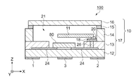
図1および図2に示すように、発振器100は、発振回路80、振動片11、容器10などを含んでいる。容器10は、発振回路80および振動片11を内包するために矩形の箱状に形成されているパッケージ本体17と、蓋体16とを有している。なお、図1では、説明の便宜上、蓋体16を透視して図示している。
As shown in FIGS. 1 and 2, the
パッケージ本体17は、パッケージ本体17の底部(−Z軸側)を形成する基板12、発振回路80の収納空間および振動片11の支持台を形成する第1枠体13、振動片11の収納空間を形成する第2枠体14、および蓋体16との接合材としてのシームリング15で構成されている。
基板12、第1枠体13、第2枠体14の材料としては、例えば、セラミックを用いることができる。シームリング15の材料としては、例えば、コバール(鉄、ニッケル、コバルトの合金)を用いることができる。パッケージ本体17は、グリーンシートを所定の形状に形成させた基板12、第1枠体13、第2枠体14を積層して焼結し、第2枠体14の上面(+Z軸側の面)にシームリング15を、例えば、銀ろうなどでろう付けすることで形成されている。なお、グリーンシートは、例えば、所定の溶液中にセラミックのパウダーを分散させ、バインダーを添加して生成される混練物がシート状に形成されたものである。また、パッケージ本体17はセラミック以外に、ガラス、樹脂などを用いることもできる。
The
As a material for the
蓋体16の材料としては、例えば、コバールを用いることができる。
パッケージ本体17は、+Z軸側に開口部を有しており、パッケージ本体17の開口部を形成しているシームリング15と蓋体16とは、例えば、抵抗溶接法(シーム溶接)などを用いて封止されている。なお、振動片11および発振回路80を収納するパッケージ本体17のキャビティー21は、窒素などの不活性気体雰囲気あるいは大気圧よりも圧力が低い減圧雰囲気となっている。
また、本実施形態では、容器10は、シームリング15を備えたパッケージ本体17と、蓋体16とを、シーム溶接を用いて封止するものと説明したが、シームリング15の備えられていないパッケージ本体と、ろう材を備えた蓋体とを用いて、ダイレクトシーム溶接で封止する方法や、炉に入れてろう材を溶かして封止する方法などであってもよい。
As a material of the
The
Further, in the present embodiment, the
パッケージ本体17の基板12の+Z軸側の面には、内部電極24が形成されている。発振回路80の−Z軸側の面には、例えば、金(Au)、はんだなどの導電性材料で形成されたバンプ(図示せず)が形成されている。
発振回路80は、このバンプを介して内部電極24に接合され、接合と同時に内部電極24と電気的に接続されている。なお、発振回路80は、接着剤などの接続部材を介して基板12の+Z軸側の面に接合され、ボンディングワイヤーなどを介して内部電極24と電気的に接続されていてもよい。
An
The
第1枠体13は、振動片11を固定する支持台としての機能を有している。第1枠体13のキャビティー21側の内壁は、第2枠体14の内壁よりキャビティー21内に延出し、+X軸方向から延出している延出部の+Z軸側の面には、内部電極18が設けられている。
振動片11は、導電性を有した接続部材20を介して内部電極18に接合支持され、内部電極18と電気的に接続されている。なお、振動片11は、導電性を有しない接続部材を介して第1枠体13の+Z軸側の面に接合され、ボンディングワイヤーなどを介して内部電極18と電気的に接続されていてもよい。
内部電極18は、第1枠体13の+Z軸側の面から−Z軸側の面に向かって貫通して配置されたビアホール26を介して内部電極24と電気的に接続されている。これにより、発振回路80と振動片11とが、電気的に接続されている。
The
The
The
図2および図3に示すように、容器10は、パッケージ本体17の基板12の−Z軸側の面に、第1端子1、第2端子2および第3端子3を備えている。詳しくは、容器10は、−Z軸方向からの平面視において、互いに対向している第1辺6および第2辺7と、第1辺6および第2辺7と交差し互いに対向している第3辺8および第4辺9と、を有している。
第1端子1は、第1辺6、第2辺7および第3辺8のうち少なくとも一つの辺に接し、第3辺8に沿った方向に配置されている。本実施形態では、第1端子1は、第1辺6、第2辺7および第3辺8に接している。
第2端子2は、第1辺6、第2辺7および第4辺9のうち少なくとも一つの辺に接し、第4辺9に沿った方向に配置されている。本実施形態では、第2端子2は、第1辺6、第2辺7および第4辺9に接している。
第3端子3は、第1端子1と第2端子2との間に設けられている。
As shown in FIGS. 2 and 3, the
The
The
The
第1端子1は、図示しない内部配線により発振回路80と電気的に接続され、第1端子1には、電圧値を可変させることができる直流電圧に基づく入力電圧が印加される。
第2端子2は、図示しない内部配線により発振回路80と、容器10の蓋体16と、図示しないシールド電極と、電気的に接続され、第2端子2には、接地電圧が印加される。
第3端子3は、図示しない内部配線により発振回路80と電気的に接続され、第3端子3からは、発振回路80から出力される第1発振信号が出力される。第3端子3は、入力電圧の印加される第1端子1と、接地電圧が印加される第2端子2と、の間に設けられているので、発振器100の近くに高周波ノイズを発する部品が実装された場合でも、これらの端子(第1端子1、第2端子2)によるシールド効果により、第1出力信号の周波数精度の劣化を低減させることができる。
The
The
The
内部電極18,24、第1端子1、第2端子2、および第3端子3の材料としては、例えば、銀(Ag)/パラジュウム(Pd)合金、タングステン(W)などを用いることができる。内部電極18,24、第1端子1、第2端子2、および第3端子3は、基板12および第1枠体13の材料であるセラミックの表面に、Ag/Pd合金またはタングステンなどをメタライズし焼成を行うことで形成することができる。その後、表面に、ニッケル(Ni)、金(Au)、銀(Ag)などの金属でメッキ処理が施されている。
As a material for the
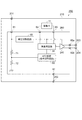
図4は、発振器100の機能ブロック図である。本実施形態の発振器100は、電圧制御型水晶発振器(VCXO:Voltage Controlled Xtal Oscillator)であり、この発振器100は、外部からの制御電圧(電圧値を可変させることができる直流電圧に基づく入力電圧)に応じて調整された周波数の発振信号が出力される。
発振器100は、発振回路80、振動片11、および発振回路80と振動片11とが内包される容器10、を含んでいる。
容器10には、外部との電気的接続を取るための第1端子1、第2端子2、および第3端子3の三つの外部接続端子が備えられている。
FIG. 4 is a functional block diagram of the
The
The
発振回路80は、発振用回路30、発振用回路30に接続されている信号調整回路および電圧調整回路60、出力バッファー40、抵抗71,72を含んで構成されている。信号調整回路は、自動周波数制御(AFC:Automatic frequency control)回路50を含んでおり、本実施形態ではAFC回路50で構成されている。発振用回路30からは、第1発振信号が発振され、第1発振信号の周波数は、AFC回路(信号調整回路)50に入力された入力電圧の電圧値に応じて調整されている。なお、発振回路80は、これらの要素の一部を省略または変更し、あるいは他の要素を追加した構成としてもよい。
The
発振回路80は、五つの端子81,82,83,84,85を備えている。
端子81は、容器10の第1端子1に接続されている。第1端子1に印加される、電圧値を可変することができる直流電圧に基づく入力電圧は、電圧調整回路60を介して発振用回路30および出力バッファー40に供給され、抵抗71を介してAFC回路50に供給される。
端子82は、容器10の第2端子2に接続されている。第2端子2に印加される接地電圧は、発振回路80に供給される。
端子83は、容器10の第3端子3に接続されている。発振用回路30から出力された第1発振信号は、出力バッファー40を介して第3端子3から出力される。
端子84は、振動片11の一端に接続され、端子85は、振動片11の他端に接続されている。振動片11は発振用回路30により発振させられる。
The
The terminal 81 is connected to the
The terminal 82 is connected to the
The terminal 83 is connected to the
The terminal 84 is connected to one end of the vibrating
ここで、従来技術による発振器400について説明する。図13は、従来技術による発振器(VCXO)400の機能ブロック図である。
発振器400は、発振回路480、振動片11、および発振回路480と振動片11とが内包される容器410、を含んでいる。
Here, a
The
容器410には、外部との電気的接続を取るための第1端子401、第2端子402、第3端子403および第4端子404の四つの外部接続端子が備えられている。
発振回路480は、発振用回路30、発振用回路30に接続されているAFC回路50および電圧調整回路60、出力バッファー40、を含んで構成されている。
The
The
発振回路480には、6つの端子481,482,483,484,485,486が備えられている。
端子481は、容器410の第1端子401に接続されている。第1端子401に印加される直流電圧は、電圧調整回路60を介して発振用回路30および出力バッファー40に供給される。
端子482は、容器410の第2端子402に接続されている。第2端子402に印加される接地電圧は、発振回路480に供給される。
端子483は、容器410の第3端子403に接続されている。発振用回路30から出力された第1発振信号は、出力バッファー40を介して第3端子403から出力される。
端子484は、容器410の第4端子404に接続されている。第4端子404に印加される、電圧値を可変することができる直流電圧は、AFC回路50に供給される。
端子485は、振動片11の一端に接続され、端子486は振動片11の他端に接続されている。振動片11は、発振用回路30により発振させられる。
The
The terminal 481 is connected to the
The terminal 482 is connected to the
The terminal 483 is connected to the
The terminal 484 is connected to the
The terminal 485 is connected to one end of the vibrating
発振器400は、第1発振信号が出力される第3端子403、接地電圧が印加される第2端子402のほかに、発振用回路30に直流電圧を印加するための第1端子401と、第1発振信号の周波数を可変させるためのAFC回路50に電圧値を可変することができる直流電圧を印加させる第4端子404と、の2系統の直流電圧印加用の外部接続端子を必要としていた。
In addition to the third terminal 403 from which the first oscillation signal is output and the
図4に戻って発振器100についての説明をする。
本実施形態の発振器100では、発振用回路30および出力バッファー40を駆動させるのに必要な直流電圧に、AFC回路50に供給する、第1発振信号の周波数を可変させるために必要な電圧値の可変幅を有する直流電圧を重畳させた1系統の電圧値を可変することができる直流電圧に基づく入力電圧が、第1端子1から印加されている。これにより、従来技術の発振器400では、四つの外部接続端子(第1端子301、第2端子302、第3端子303、第4端子304)を必要としていたが、本実施形態の発振器100では、三つの外部接続端子(第1端子1、第2端子2、第3端子3)で構成させることができる。この構成によれば、接地電圧が印加される端子以外の直流電圧印加用に必要な外部接続端子数を二つから一つに削減させることができるので、発振器100を小型化することができる。また、この重畳された入力電圧は、周波数信号を含んでいないため、第1発振信号に対するノイズとなる可能性が低減し、外部接続端子数を減らすことにより生じる周波数精度の低下を抑えることができる。
Returning to FIG. 4, the
In the
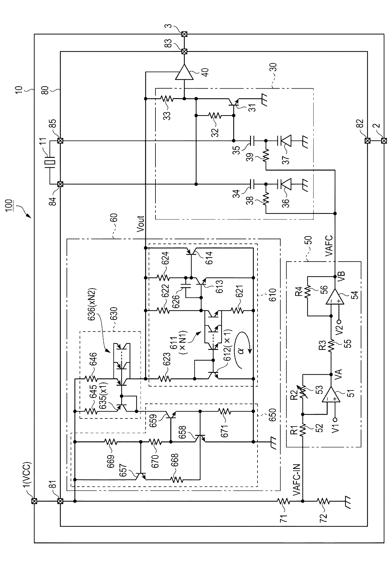
次に、AFC回路50の構成について説明する。
AFC回路50は、演算増幅器51、抵抗値がR1の抵抗52、抵抗値がR2の可変抵抗53、演算増幅器54、抵抗値がR3の抵抗55、抵抗値がR4の抵抗56を含んで構成されている。
Next, the configuration of the
The
AFC回路50の入力電圧(VAFC_IN)には、第1端子1から印加された、電圧値を可変することができる直流電圧に基づく入力電圧(VCC)が、抵抗71と抵抗72とで構成されている抵抗分圧回路を介して、所定の電圧値に変換され印加されている。AFC回路50の入力端である抵抗52は、端子81を介して第1端子1に接続されている抵抗71と、抵抗71に直列に接続されている抵抗72と、の中点に接続されている。例えば、第1端子1に、4±1Vに可変することができる入力電圧(VCC)が印加され、抵抗71と抵抗72とに100Ωの抵抗が接続されている場合、AFC回路50の入力電圧(VAFC_IN)には、2±0.5Vの直流電圧を印加させることができる。
As the input voltage (VAFC_IN) of the
抵抗52は、抵抗分圧回路を構成する抵抗71と抵抗72との中点と、演算増幅器51の反転入力端子(−端子)との間に接続されており、可変抵抗53は、演算増幅器51の反転入力端子(−端子)と、出力端子との間に接続されている。また、演算増幅器51の非反転入力端子(+端子)には一定電圧(V1)が入力される。
The
抵抗55は、演算増幅器51の出力端子と、演算増幅器54の反転入力端子(−端子)との間に接続されており、抵抗56は、演算増幅器54の反転入力端子(−端子)と、出力端子との間に接続されている。また、演算増幅器54の非反転入力端子(+端子)には一定電圧(V2)が入力され、演算増幅器54の出力端子は発振用回路30の抵抗38,39に接続されている。
The
可変抵抗53の抵抗値R2は、図示しないメモリーに記憶されているゲイン調整値に応じた抵抗値となる。
The resistance value R2 of the
このように構成されているAFC回路50において、入力電圧(VAFC_IN)と、演算増幅器51の出力電圧(VA)とは次式(1)で表される。
In the
また、演算増幅器54の出力電圧(VB)は次式(2)で表される。
The output voltage (VB) of the
次に、発振用回路30の構成について説明する。
発振用回路30は、端子84および端子85に接続され、端子84および端子85に接続されている振動片11を発振させる。図4の例では、発振用回路30は、NPN型のバイポーラトランジスター31、抵抗32,33、コンデンサー34,35、バラクター(可変容量素子)36,37、抵抗38,39を含んで構成されている。
Next, the configuration of the
The
バイポーラトランジスター31は、ベース端子が端子85に接続され、コレクター端子が端子84に接続され、エミッター端子が接地されている。
The
抵抗32は、バイポーラトランジスター31のベース端子とコレクター端子との間に接続されており、抵抗33は、電圧調整回路60の出力端子とバイポーラトランジスター31のコレクター端子との間に接続されている。
The
コンデンサー34は、バイポーラトランジスター31のコレクター端子とバラクター36のカソード端子との間に接続されており、コンデンサー35は、バイポーラトランジスター31のベース端子とバラクター37のカソード端子との間に接続されている。
The
バラクター36のアノード端子及びバラクター37のアノード端子は接地されている。
The anode terminal of the
抵抗38は、AFC回路50の出力端子と、バラクター36のカソード端子との間に接続されており、抵抗39は、AFC回路50の出力端子と、バラクター37のカソード端子との間に接続されている。
The
このように構成されている発振用回路30は、バイポーラトランジスター31を増幅素子として、端子85から入力される振動片11の出力信号を増幅し、端子84を介してこの増幅した信号を振動片11の入力信号として供給する。なお、発振用回路30は、増幅素子として、PNP型のバイポーラトランジスター、電界効果トランジスター(FET:Field Effect Transistor)、金属酸化膜型電界効果トランジスター(MOSFET:Metal Oxide Semiconductor Field Effect Transistor)、サイリスター等を用いて実現されてもよい。
The
発振用回路30の第1発振信号である、バイポーラトランジスター31のコレクター端子から出力される第1発振信号は出力バッファー40に入力され、出力バッファー40から出力される第1発振信号は端子83を介して容器10の第3端子3から外部に出力される。
The first oscillation signal output from the collector terminal of the
バラクター36,37のカソード端子には、第1端子1の電圧値に基づいて生成されたAFC回路50の出力電圧(VAFC)が印加され、この出力電圧(VAFC)の電圧値に応じて、バラクター36,37の容量値が設定され、発振用回路30から発振される第1発振信号の周波数が調整される。例えば、V2=V1,R3=R4として、上記の式(1)を式(2)に代入して整理すると、AFC回路50の出力電圧(VAFC)は次式(3)で表される。
The output voltage (VAFC) of the
式(3)によって示されるように、AFC回路50のゲインはR2/R1であり、VAFCはVAFC_IN、すなわち、第1端子1から入力される、電圧値を可変することができる直流電圧に基づく入力電圧の電圧値によって制御される。
As shown by the expression (3), the gain of the
次に、電圧調整回路60の構成について説明する。
電圧調整回路60は、基準電圧発生回路610と、カレントミラー回路630と、基準電流発生源650と、を含んで構成されている。
Next, the configuration of the
The
まず、基準電圧発生回路610について説明する。
基準電圧発生回路610は、トランジスター611,612,613,614と、抵抗621,622,623,624と、コンデンサー626と、を含んで構成されている。
トランジスター611,612は、N1:1(図には×N1、×1にて表示)のエミッター面積比を有している。トランジスター611,612のベース端子同士が接続されると共に、トランジスター611のエミッター端子は、抵抗621を介して接地されている。そして、トランジスター612のエミッター端子が接地されると共に、ベース端子とコレクター端子との間が接続されている。トランジスター611,612のそれぞれのコレクター端子と、出力端子Voutとの間が抵抗622,623を介して接続されている。さらに、トランジスター611のコレクター端子とトランジスター613のベース端子とが接続されると共に、トランジスター613のエミッター端子が接地されている。トランジスター613のコレクター端子とベース端子との間が、コンデンサー626を介して接続され、コレクター端子と出力端子Voutとの間が、抵抗624を介して接続されている。そして、トランジスター613のコレクター端子とトランジスター614のベース端子とが接続されると共に、トランジスター614のコレクター端子が接地され、エミッター端子が出力端子Voutに接続されている。トランジスター611,612と抵抗621とでバンドギャップループαが構成されている。
First, the reference
The reference
The
次に、カレントミラー回路630、基準電流発生源650について説明する。
上述の基準電圧発生回路610は、電流供給回路として、トランジスター635,636および抵抗645,646とを含んで構成されているカレントミラー回路630と、トランジスター657,658,659と抵抗668,669,670,671とを含んで構成されている基準電流発生源650と、を備えている。
トランジスター635,636は、1:N2(図には×1、×N2にて表示)のエミッター面積比を有している。トランジスター635,636のベース端子同士が接続されると共に、トランジスター635のベース端子とコレクター端子との間が接続されている。トランジスター635,636のエミッター端子はそれぞれ抵抗645,646を介して端子81に接続され、容器10の第1端子1(VCC)に接続されている。トランジスター636のコレクター端子は出力端子Voutに接続されている。さらに、トランジスター657のコレクター端子が容器10の第1端子1(VCC)に接続されると共に、エミッター端子とトランジスター658のベース端子とが抵抗668を介して接続されている。トランジスター657のベース端子と容器10の第1端子1(VCC)との間が抵抗669を介して接続されると共に、トランジスター657のベースとトランジスター658のコレクターとの間が抵抗670を介して接続されている。そして、トランジスター658のコレクター端子とトランジスター659のベース端子とが接続されると共に、トランジスター658のエミッター端子が接地されている。トランジスター659とトランジスター635のコレクター端子同士が接続され、トランジスター659のエミッター端子とトランジスター658のベース端子とが接続されている。トランジスター659のエミッター端子とトランジスター658のベース端子との接続点は、抵抗671を介して接地されている。
Next, the
The reference
The
上述の電圧調整回路60を用いることで、第1端子1に印加された、電圧値を可変することができる直流電圧に基づく入力電圧を、所定の電圧値(定電圧値)に変換させて発振用回路30および出力バッファー40に入力させることができる。例えば、第1端子1から発振回路80の端子81を介して電圧調整回路60に、4±1Vに電圧値を可変することができる直流電圧に基づく入力電圧が印加された場合、電圧調整回路60の出力端子Voutから3Vの直流電圧を出力させることができる。なお、本実施形態で示した電圧調整回路60は一例であり、他の構成の電圧調整回路を用いてもよい。
By using the
なお、本実施形態ではVCXOとして説明したが、本発明は発振信号の周波数を電圧で制御させる発振器に適応することができる。 Although this embodiment has been described as VCXO, the present invention can be applied to an oscillator that controls the frequency of an oscillation signal with a voltage.
以上述べたように、本実施形態に係る発振器100によれば、以下の効果を得ることができる。
発振器100は、発振回路80、振動片11および容器10を含んでおり、発振回路80は、発振用回路30、AFC回路50および電圧調整回路60を含んで構成されている。容器10は、第1端子1と、第2端子2と、第3端子3と、を備えている。
発振用回路30には、第1端子1を介して電圧値を可変することができる直流電圧に基づく入力電圧が、電圧調整回路60で所定の電圧値(定電圧値)に変換されて印加されている。AFC回路50には、第1端子1を介して、電圧値を可変することができる直流電圧に基づく入力電圧が、抵抗71と抵抗72とで構成されている抵抗分圧回路で、電圧値が所定の比率で変換されて印加されている。従来技術では、発振用回路30に印加させる、所定の電圧値を有する直流電圧と、第1発振信号の周波数を調整するためにAFC回路50に印加させる、電圧値を可変することができる直流電圧と、の2系統で電源を供給させる必要があったが、本実施形態の発振器100(発振回路80)では、これを第1端子1からの1系統の電圧値を可変することができる直流電圧に基づく入力電圧で供給させることができる。
これにより、第1発振信号の周波数を調整することが可能な発振器(VCXO)100を、入力電圧を印加させる第1端子1と、接地電圧が印加される第2端子2と、第1発振信号が出力される第3端子3と、の三つの外部接続端子を備えた小型の容器10で構成させることができる。また、この重畳された入力電圧は、周波数信号を含んでいないため、第1発振信号に対するノイズとなる可能性が低減するので、第1発振信号の周波数精度の低下を抑えることができる。
したがって、外部接続端子数を減らすことにより生じる周波数精度の低下を抑えて発振器の小型化を図ることが可能な発振回路80、および小型化を図った発振器100を提供することができる。
As described above, according to the
The
An input voltage based on a DC voltage whose voltage value can be varied via the
Thus, the oscillator (VCXO) 100 capable of adjusting the frequency of the first oscillation signal includes the
Therefore, it is possible to provide the
(実施形態2)
実施形態2に係る発振器200では、第2発振信号を出力する第4端子を備え、差動出力に対応しているところが、実施形態1と異なっている。
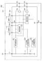
図5は、実施形態2に係る発振器200の図1におけるA−A線での断面図である。図6は、発振器200の外部接続端子を示す模式平面図である。図7は、発振器200の機能ブロック図である。なお、図7では、図4と同一内部構造である、発振用回路30、AFC回路50、および電圧調整回路60の内部構造の図示を省略している。
まず、実施形態2に係る発振器200の概略構成について、図5から図7を用いて説明する。なお、実施形態1の発振器100と同一の構成部位については、同一の符号を附し、重複する説明は省略する。
(Embodiment 2)
The
FIG. 5 is a cross-sectional view of the
First, a schematic configuration of the
図5に示すように、発振器200は、発振回路280、振動片11、容器210などを含んで構成されている。容器210は、発振回路280および振動片11を内包するために矩形の箱状に形成されているパッケージ本体217と、蓋体16とを有している。容器210の−Z軸側の面には、外部との電気的接続を取るための第1端子201、第2端子202、第3端子203、第4端子204の四つの外部接続端子が備えられている。
As shown in FIG. 5, the
図5および図6に示すように、パッケージ本体217の基板12の−Z軸側の面には、第1端子201、第2端子202、第3端子203、および第4端子204が設けられている。詳しくは、容器210は、−Z軸方向からの平面視において、互いに対向している第1辺6および第2辺7と、第1辺6および第2辺7と交差し互いに対向している第3辺8および第4辺9と、を有している。
第1端子201は、第1辺6、第2辺7および第3辺8のうち少なくとも一つに接し、第3辺8に沿った方向に配置されている。本実施形態では、第1端子201は、第1辺6、第2辺7および第3辺8に接している。
第2端子202は、第1辺6、第2辺7および第4辺9のうち少なくとも一つに接し、第4辺9に沿った方向に配置されている。本実施形態では、第2端子202は、第1辺6、第2辺7および第4辺9に接している。
第3端子203は、第1端子201と第2端子202との間に設けられている。
第4端子204は、第1端子201および第2端子202のいずれか一方と、第3端子203と、の間に設けられている。本実施形態では、第4端子204は、第2端子202と第3端子203との間に設けられている。
As shown in FIGS. 5 and 6, a
The
The
The
The
第1端子201は、図示しない内部配線により発振回路280に電気的に接続され、第1端子201には、電圧値を可変させることができる直流電圧に基づく入力電圧が印加されている。
第2端子202は、図示しない内部配線により発振回路280と、容器210の蓋体16と、図示しないシールド電極と、に電気的に接続され、第2端子202には、接地電圧が印加されている。
第3端子203、第4端子204は、図示しない内部配線により発振回路280に電気的に接続され、第3端子203からは、発振回路280から出力される第1発振信号が出力され、第4端子204からは、第1発振信号と180度位相が異なる第2発振信号が出力される。第3端子203および第4端子204は、入力電圧の印加される第1端子201と、接地電圧が印加される第2端子202と、の間に設けられているので、発振器200の近くに高周波ノイズを発する部品が実装された場合でも、これらの端子(第1端子201、第2端子202)によるシールド効果により、第1出力信号および第2発振信号の周波数精度の劣化を低減させることができる。
The
The
The
図7に示すように、発振回路280は、六つの端子81,82,83a,83b,84,85を備えている。
端子81は、容器210の第1端子201に接続されている。第1端子201に供給される、電圧値を可変することができる直流電圧に基づく入力電圧は、電圧調整回路60を介して発振用回路30および出力バッファー240に供給され、抵抗71を介してAFC回路50に供給される。
端子82は、容器210の第2端子202に接続されている。第2端子202に印加される接地電圧は、発振回路280に供給される。
端子83aは、容器210の第3端子203に接続されている。発振用回路30から出力された第1発振信号は、出力バッファー240を介して第3端子203から出力される。
端子83bは、容器210の第4端子204に接続されている。発振用回路30から出力された第1発振信号は、出力バッファー240を介して第4端子204から出力される。
As shown in FIG. 7, the
The terminal 81 is connected to the
The terminal 82 is connected to the
The terminal 83a is connected to the
The terminal 83b is connected to the
発振用回路30のシングルエンド出力の発振信号は、差動信号処理機能を備えている出力バッファー240に入力される。シングルエンド出力の発振信号は、出力バッファー240で互いに180度の位相差を有した第1発振信号および第2発振信号の差動出力に変換される。第1発振信号は、端子83aを介して容器210の第3端子203から外部に出力され、第2発振信号は、端子83bを介して容器210の第4端子204から外部に出力される。
The single-ended output oscillation signal of the
以上述べたように、本実施形態に係る発振器200よれば、以下の効果を得ることができる。
発振器200は、発振回路280、振動片11および容器210を含んでおり、発振回路280は、発振用回路30、AFC回路50、電圧調整回路60、および出力バッファー240を含んで構成されている。容器210は、第1端子201と、第2端子202と、第3端子203と、第4端子204を備えている。
発振回路280には電圧調整回路60を介して、AFC回路50には抵抗分圧回路を介して、第1端子201から電圧値を可変することができる直流電圧に基づく入力電圧が印加されている。これにより、発振器200に必要な接地電圧以外の直流電圧が2系統から1系統に削減されるので、容器210の接地電圧が印加される端子以外の直流電圧を入力するのに必要な外部接続端子数を二つから一つに削減させることができる。
発振回路280は、差動信号処理機能を備えている出力バッファー240を有しているので、互いに180度の位相差を有した第1発振信号と、第2発振信号とを、容器210の第3端子203と第4端子204とから外部に出力させることができる。
したがって、4端子の小型な容器210で構成された差動出力機能を備えた発振器(VCXO)200を提供することができる。
As described above, according to the
The
An input voltage based on a DC voltage whose voltage value can be varied is applied from the
Since the
Therefore, it is possible to provide an oscillator (VCXO) 200 having a differential output function configured by a
なお、本発明は上述した実施形態に限定されず、実施形態に種々の変更や改良などを加えることが可能である。変形例を以下に述べる。 In addition, this invention is not limited to embodiment mentioned above, A various change, improvement, etc. can be added to embodiment. A modification will be described below.
(変形例)
変形例に係る発振器300では、周波数の異なる第1発振信号と第2発振信号とが出力されるところが、実施形態2と異なっている。
図8は、変形例に係る発振器300の機能ブロック図である。変形例に係る発振器300の概略構成について、図8を用いて説明する。なお、実施形態2の発振器200と同一の構成部位については、同一の符号を附し、重複する説明は省略する。
(Modification)
The
FIG. 8 is a functional block diagram of an
図8に示すように、発振器300は、発振回路380、振動片11a,11b、容器210などを含んで構成されている。
発振回路380は、八つの端子81,82,83a,83b,84a,84b,85a,85bを備えている。
発振回路380は、第1発振信号を生成する発振用回路30a,出力バッファー40a,AFC回路50aと、第2発振信号を生成する発振用回路30b,出力バッファー40b,AFC回路50bと、電圧調整回路60と、抵抗分圧回路を構成する抵抗71,72と、を含んで構成されている。
As shown in FIG. 8, the
The
The
端子81は、容器210の第1端子201に接続されている。第1端子201に供給される、電圧値を可変することができる直流電圧に基づく入力電圧は、電圧調整回路60を介した発振用回路30a,30bおよび出力バッファー40a,40bと、抵抗分圧回路を構成する抵抗71を介したAFC回路50a,50bと、に供給される。
端子82は、容器210の第2端子202に接続されている。第2端子202に印加される接地電圧は、発振回路380に供給される。
端子83aは、容器210の第3端子203に接続されている。発振用回路30aから出力された第1発振信号は、出力バッファー40aを介して第3端子203から出力される。
端子83bは、容器210の第4端子204に接続されている。発振用回路30bから出力された第2発振信号は、出力バッファー40bを介して第4端子204から出力される。
端子84aは、振動片11aの一端に接続され、端子85aは振動片11aの他端に接続されている。振動片11aは発振用回路30aにより発振させられる。
端子84bは、振動片11bの一端に接続され、端子85bは振動片11bの他端に接続されている。振動片11bは発振用回路30bにより発振させられる。
The terminal 81 is connected to the
The terminal 82 is connected to the
The terminal 83a is connected to the
The terminal 83b is connected to the
The terminal 84a is connected to one end of the vibrating
The terminal 84b is connected to one end of the vibrating
発振用回路30a,30bの内部構造は、発振器200(発振器100)の発振用回路30と同じであり、AFC回路50a,50bの内部構造は、発振器200(発振器100)のAFC回路50と同じであるので、その説明を省略する。
The internal structures of the
以上述べたように、本変形例に係る発振器300によれば、上述の実施形態2での効果に加えて、以下の効果を得ることができる。
発振器300は、第1発振信号を出力させる振動片11a、発振用回路30a、AFC回路50a、出力バッファー40aと、第2発振信号を出力させる振動片11b、発振用回路30b、AFC回路50b、出力バッファー40bと、を備えているので、周波数の異なる第1発振信号と、第2発振信号とを出力させることができる。
発振用回路30a,30bには電圧調整回路60を介して、AFC回路50a,50bには抵抗分圧回路を介して、第1端子1から電圧値を可変することができる直流電圧に基づく入力電圧が印加されている。これにより、発振器300に必要な接地電圧以外の直流電圧が2系統から1系統に削減されるため、容器210の接地電圧が印加される端子以外の直流電圧を入力するのに必要な外部接続端子数を二つから一つに削減させることができる。
したがって、4端子の小型な容器210で構成された異なる周波数の発振信号を出力させる機能を備えた発振器(VCXO)300を提供することができる。なお、本変形例では、第1発振信号と第2発振信号とは異なる周波数として説明したが、第1発振信号と第2発振信号とは同じ周波数であってもよい。
As described above, according to the
The
An input voltage based on a DC voltage whose voltage value can be varied from the
Therefore, it is possible to provide an oscillator (VCXO) 300 having a function of outputting oscillation signals having different frequencies, which is constituted by a
<電子機器>
次に、本発明の実施形態に係る発振回路(発振器)を備えた電子機器について図9から図11を用いて説明する。なお、本説明では、発振器100(発振回路80)を用いた例を示している。
<Electronic equipment>
Next, an electronic apparatus provided with an oscillation circuit (oscillator) according to an embodiment of the present invention will be described with reference to FIGS. In this description, an example using the oscillator 100 (oscillation circuit 80) is shown.
図9は、本発明の一実施形態に係る発振器100(発振回路80)を備える電子機器の一例としてのモバイル型(又はノート型)のパーソナルコンピューター1100の構成の概略を示す斜視図である。図9に示すように、パーソナルコンピューター1100は、キーボード1102を備えた本体部1104と、表示部1000を備えた表示ユニット1106とにより構成され、表示ユニット1106は、本体部1104に対しヒンジ構造部を介して回動可能に支持されている。このようなパーソナルコンピューター1100には、発振器100(発振回路80)が内蔵されている。
FIG. 9 is a perspective view schematically illustrating a configuration of a mobile (or notebook)
上述のように、電子機器の一例としてのモバイル型(又はノート型)パーソナルコンピューター1100に、本発明の一実施形態に係る発振器100(発振回路80)を、例えば、クロック源として備えることにより、モバイル型パーソナルコンピューター1100を小型化することができる。また、本発明の一実施形態に係る発振器100(発振回路80)は、例えば、モバイル型パーソナルコンピューター1100に供給されるクロック源として出力される信号の出力端子が、入力電圧が印加される端子と接地電圧が印加される端子との間に配置されていることでシールドされるため、クロック源として出力される信号の周波数精度の劣化を低減でき、モバイル型パーソナルコンピューター1100の動作の信頼性を向上することができる。
As described above, a mobile type (or notebook type)
図10は、本発明の一実施形態に係る発振器100(発振回路80)を備える電子機器の一例としての携帯電話機1200(PHSも含む)の構成の概略を示す斜視図である。図10に示すように、携帯電話機1200は、複数の操作ボタン1202、受話口1204および送話口1206を備え、操作ボタン1202と受話口1204との間には、表示部1000が配置されている。このような携帯電話機1200には、発振器100(発振回路80)が内蔵されている。
FIG. 10 is a perspective view schematically illustrating a configuration of a mobile phone 1200 (including PHS) as an example of an electronic apparatus including the oscillator 100 (oscillation circuit 80) according to an embodiment of the present invention. As shown in FIG. 10, the
上述のように、電子機器の一例としての携帯電話機(PHSを含む)1200に、本発明の一実施形態に係る発振器100(発振回路80)を、例えば、クロック源として備えることにより、携帯電話機1200を小型化することができる。また、本発明の一実施形態に係る発振器100(発振回路80)は、例えば、携帯電話機1200に供給されるクロック源として出力される信号の出力端子が、入力電圧が印加される端子と接地電圧が印加される端子との間に配置されていることでシールドされるため、クロック源として出力される信号の周波数精度の劣化を低減でき、携帯電話機1200の動作の信頼性を向上することができる。
As described above, the mobile phone 1200 (including the PHS) 1200 as an example of the electronic apparatus includes the oscillator 100 (oscillation circuit 80) according to the embodiment of the present invention as a clock source, for example. Can be miniaturized. The oscillator 100 (oscillation circuit 80) according to an embodiment of the present invention includes, for example, an output terminal of a signal output as a clock source supplied to the
図11は、本発明の一実施形態に係る発振器100(発振回路80)を備える電子機器の一例としてのデジタルカメラ1300の構成の概略を示す斜視図である。なお、図11には、外部機器との接続についても簡易的に示されている。ここで、従来のフィルムカメラは、被写体の光像により銀塩写真フィルムを感光するのに対し、デジタルカメラ1300は、被写体の光像をCCD(Charge Coupled Device)などの撮像素子により光電変換して撮像信号(画像信号)を生成する。
デジタルカメラ1300におけるケース(ボディー)1302の背面には、表示部1000が設けられ、CCDによる撮像信号に基づいて表示を行う構成になっており、表示部1000は、被写体を電子画像として表示するファインダーとして機能する。また、ケース1302の正面側(図中裏面側)には、光学レンズ(撮像光学系)やCCDなどを含む受光ユニット1304が設けられている。
FIG. 11 is a perspective view illustrating a schematic configuration of a
A
撮影者が表示部1000に表示された被写体像を確認し、シャッターボタン1306を押下すると、その時点におけるCCDの撮像信号が、メモリー1308に転送・格納される。また、このデジタルカメラ1300においては、ケース1302の側面に、ビデオ信号の出力端子1312と、データ通信用の入出力端子1314とが設けられている。そして、図示されるように、ビデオ信号の出力端子1312にはテレビモニター1430が、データ通信用の入出力端子1314にはパーソナルコンピューター1440が、それぞれ必要に応じて接続される。さらに、所定の操作により、メモリー1308に格納された撮像信号が、テレビモニター1430や、パーソナルコンピューター1440に出力される構成になっている。このようなデジタルカメラ1300には、発振器100(発振回路80が内蔵されている。
When the photographer confirms the subject image displayed on the
上述のように、電子機器の一例としてのデジタルカメラ1300に、本発明の一実施形態に係る発振器100(発振回路80)を、例えば、クロック源として備えることにより、デジタルカメラ1300を小型化することができる。また、本発明の一実施形態に係る発振器100(発振回路80)は、例えば、デジタルカメラ1300に供給されるクロック源として出力される信号の出力端子が、入力電圧が印加される端子と接地電圧が印加される端子との間に配置されていることでシールドされるため、クロック源として出力される信号の周波数精度の劣化を低減でき、デジタルカメラ1300の動作の信頼性を向上することができる。
As described above, the
なお、本発明の一実施形態に係る発振器100(発振回路80)は、図9のパーソナルコンピューター1100(モバイル型パーソナルコンピューター)、図10の携帯電話機1200、図11のデジタルカメラ1300の他にも、例えば、インクジェット式吐出装置(例えばインクジェットプリンター)、ラップトップ型パーソナルコンピューター、タブレット型パーソナルコンピューター、ルーターやスイッチなどのストレージエリアネットワーク機器、ローカルエリアネットワーク機器、移動体端末基地局用機器、テレビ、ビデオカメラ、ビデオレコーダー、カーナビゲーション装置、ページャー、電子手帳(通信機能付も含む)、電子辞書、電卓、電子ゲーム機器、ワードプロセッサー、ワークステーション、テレビ電話、防犯用テレビモニター、電子双眼鏡、POS端末、医療機器(例えば電子体温計、血圧計、血糖計、心電図計測装置、超音波診断装置、電子内視鏡)、魚群探知機、各種測定機器、計器類(例えば、車両、航空機、船舶の計器類)、フライトシミュレーター、ヘッドマウントディスプレイ、モーショントレース、モーショントラッキング、モーションコントローラー、PDR(歩行者位置方位計測)などの電子機器に適用することができる。
The oscillator 100 (oscillation circuit 80) according to an embodiment of the present invention includes a personal computer 1100 (mobile personal computer) in FIG. 9, a
<移動体>
次に、本発明の実施形態に係る発振回路(発振器)を備えた移動体について図12を用いて説明する。なお、本説明では、発振器100(発振回路80)を用いた例を示している。
図12は、本発明の一実施形態に係る発振器100(発振回路80)を備える移動体の一例としての自動車1500を概略的に示す斜視図である。
<Moving object>
Next, a moving body provided with an oscillation circuit (oscillator) according to an embodiment of the present invention will be described with reference to FIG. In this description, an example using the oscillator 100 (oscillation circuit 80) is shown.
FIG. 12 is a perspective view schematically showing an
自動車1500には上記実施形態に係る発振器100(発振回路80)が搭載されている。図12に示すように、移動体としての自動車1500には、発振器100(発振回路80)を内蔵してタイヤなどを制御する電子制御ユニット1510が車体に搭載されている。また、発振器100(発振回路80)は、他にもキーレスエントリー、イモビライザー、カーナビゲーションシステム、カーエアコン、アンチロックブレーキシステム(ABS)、エアバック、タイヤ・プレッシャー・モニタリング・システム(TPMS:Tire Pressure Monitoring System)、エンジンコントロール、ブレーキシステム、ハイブリッド自動車や電気自動車の電池モニター、車体姿勢制御システム、などの電子制御ユニット(ECU:Electronic Control Unit)に広く適用できる。
The
上記のように、移動体の一例としての自動車1500に、本発明の一実施形態に係る発振器100(発振回路80)を、例えば、クロック源として備えることにより、自動車1500および電子制御ユニット1510のうち少なくとも一方を小型化することができる。また、本発明の一実施形態に係る発振器100(発振回路80)は、例えば、自動車1500および電子制御ユニット1510のうち少なくとも一方に供給されるクロック源として出力される信号の出力端子が、入力電圧が印加される端子と接地電圧が印加される端子との間に配置されていることでシールドされるため、クロック源として出力される信号の周波数精度の劣化を低減でき、自動車1500および電子制御ユニット1510のうち少なくとも一方の動作の信頼性を向上することができる。
As described above, by providing the
1…第1端子、2…第2端子、3…第3端子、4…第4端子、6…第1辺、7…第2辺、8…第3辺、9…第4辺、10,210,410…容器、11,11a,11b…振動片、12…基板、13…第1枠体、14…第2枠体、15…シームリング、16…蓋体、17,217…パッケージ本体、18,24…内部電極、20…接続部材、21…キャビティー、26…ビアホール、30,30a,30b…発振用回路、31…バイポーラトランジスター、36,37…バラクター、40,40a,40b,240…出力バッファー、50…AFC回路(信号調整回路)、51,54…演算増幅器、53…可変抵抗、60…電圧調整回路、80,280,380,480…発振回路、100,200,300,400…発振器、610…基準電圧発生回路、611,612,613,614,635,636,657,658,659…トランジスター、630…カレントミラー回路、650…基準電流発生源、1100…パーソナルコンピューター、1200…携帯電話機、1300…デジタルカメラ、1500…自動車。
DESCRIPTION OF
Claims (8)
前記発振用回路に接続されている信号調整回路と、を備え、
前記発振用回路および前記信号調整回路には、電圧値を可変させることができる直流電圧に基づく入力電圧が入力され、
前記発振用回路は、振動片を発振させると共に、第1発振信号を出力し、
前記第1発振信号の周波数は、前記信号調整回路から出力される電圧値に応じて調整されること、を特徴とする発振回路。 An oscillation circuit;
A signal adjustment circuit connected to the oscillation circuit,
The oscillation circuit and the signal adjustment circuit are input with an input voltage based on a DC voltage whose voltage value can be varied,
The oscillation circuit oscillates the resonator element and outputs a first oscillation signal,
An oscillation circuit, wherein the frequency of the first oscillation signal is adjusted according to a voltage value output from the signal adjustment circuit.
前記電圧調整回路は、前記入力電圧が入力されて前記直流電圧を所定の電圧値に変換して前記発振用回路に出力すること、を特徴とする請求項1に記載の発振回路。 A voltage adjustment circuit connected to the oscillation circuit;
2. The oscillation circuit according to claim 1, wherein the voltage adjustment circuit receives the input voltage, converts the DC voltage into a predetermined voltage value, and outputs the voltage value to the oscillation circuit.
前記可変容量素子の静電容量値は、前記信号調整回路から出力される電圧値に応じて設定されること、を特徴とする請求項1または2に記載の発振回路。 The oscillation circuit includes a variable capacitance element,
The oscillation circuit according to claim 1, wherein the capacitance value of the variable capacitance element is set according to a voltage value output from the signal adjustment circuit.
振動片と、
前記発振回路と前記振動片とが内包される容器と、を含み、
前記容器は、平面視において、互いに対向している第1辺および第2辺と、
前記第1辺および前記第2辺と交差し互いに対向している第3辺および第4辺と、
前記第1辺、前記第2辺、前記第3辺のうち少なくとも一つの辺に接し、前記第3辺に沿った方向に配置されている第1端子と、
前記第1辺、前記第2辺、前記第4辺のうち少なくとも一つの辺に接し、前記第4辺に沿った方向に配置されている第2端子と、
前記第1端子と前記第2端子との間に設けられている第3端子と、を有し、
前記第1端子は、電圧値を可変させることができる直流電圧に基づく入力電圧が印加される端子であり、
前記第2端子は、接地電圧が印加される端子であり、
前記第3端子は、前記発振回路から出力される第1発振信号が出力される端子であること、を特徴とする発振器。 An oscillation circuit according to any one of claims 1 to 4,
A vibrating piece,
A container in which the oscillation circuit and the resonator element are contained,
The container has a first side and a second side facing each other in plan view;
A third side and a fourth side crossing the first side and the second side and facing each other;
A first terminal that is in contact with at least one of the first side, the second side, and the third side and is disposed in a direction along the third side;
A second terminal that is in contact with at least one of the first side, the second side, and the fourth side, and is disposed in a direction along the fourth side;
A third terminal provided between the first terminal and the second terminal,
The first terminal is a terminal to which an input voltage based on a DC voltage whose voltage value can be varied is applied,
The second terminal is a terminal to which a ground voltage is applied,
The oscillator is characterized in that the third terminal is a terminal from which a first oscillation signal output from the oscillation circuit is output.
前記第4端子は、前記発振回路から出力される第2発振信号が出力される端子であること、を特徴とする請求項5に記載の発振器。 The container includes a fourth terminal provided between any one of the first terminal and the second terminal and the third terminal,
The oscillator according to claim 5, wherein the fourth terminal is a terminal to which a second oscillation signal output from the oscillation circuit is output.
Priority Applications (3)
| Application Number | Priority Date | Filing Date | Title |
|---|---|---|---|
| JP2014124061A JP2016005118A (en) | 2014-06-17 | 2014-06-17 | Oscillation circuit, oscillator, electronic apparatus, and mobile |
| CN201510319627.8A CN105322889A (en) | 2014-06-17 | 2015-06-11 | Oscillation circuit, oscillator, electronic apparatus, and moving object |
| US14/740,444 US9621107B2 (en) | 2014-06-17 | 2015-06-16 | Oscillation circuit, oscillator, electronic apparatus, and moving object |
Applications Claiming Priority (1)
| Application Number | Priority Date | Filing Date | Title |
|---|---|---|---|
| JP2014124061A JP2016005118A (en) | 2014-06-17 | 2014-06-17 | Oscillation circuit, oscillator, electronic apparatus, and mobile |
Publications (1)
| Publication Number | Publication Date |
|---|---|
| JP2016005118A true JP2016005118A (en) | 2016-01-12 |
Family
ID=54837023
Family Applications (1)
| Application Number | Title | Priority Date | Filing Date |
|---|---|---|---|
| JP2014124061A Pending JP2016005118A (en) | 2014-06-17 | 2014-06-17 | Oscillation circuit, oscillator, electronic apparatus, and mobile |
Country Status (3)
| Country | Link |
|---|---|
| US (1) | US9621107B2 (en) |
| JP (1) | JP2016005118A (en) |
| CN (1) | CN105322889A (en) |
Citations (4)
| Publication number | Priority date | Publication date | Assignee | Title |
|---|---|---|---|---|
| JP2009246685A (en) * | 2008-03-31 | 2009-10-22 | Fujitsu Ten Ltd | Demodulating device, antenna device and receiving device |
| JP2009290381A (en) * | 2008-05-27 | 2009-12-10 | Kyocera Kinseki Corp | Oscillator |
| JP2013162358A (en) * | 2012-02-06 | 2013-08-19 | Seiko Epson Corp | Oscillator circuit, semiconductor integrated circuit element, electronic equipment, and output control method of semiconductor integrated circuit element |
| JP2013207686A (en) * | 2012-03-29 | 2013-10-07 | Nippon Dempa Kogyo Co Ltd | Crystal oscillator |
Family Cites Families (25)
| Publication number | Priority date | Publication date | Assignee | Title |
|---|---|---|---|---|
| JPS622813Y2 (en) * | 1979-07-20 | 1987-01-22 | ||
| JPH02180410A (en) * | 1988-07-25 | 1990-07-13 | Nippon Dempa Kogyo Co Ltd | Temperature compensating multi-frequency oscillator |
| JPH03171907A (en) | 1989-11-30 | 1991-07-25 | Nec Corp | Piezoelectric oscillator |
| JP3171907B2 (en) | 1991-02-15 | 2001-06-04 | 日東電工株式会社 | Sliding sheet |
| JPH08288741A (en) * | 1995-04-14 | 1996-11-01 | Matsushita Electric Ind Co Ltd | Crystal oscillator and adjusting method therefor |
| JPH104318A (en) * | 1996-04-15 | 1998-01-06 | Mitsumi Electric Co Ltd | Temperature compensation type crystal oscillator |
| JP3536561B2 (en) * | 1996-12-04 | 2004-06-14 | セイコーエプソン株式会社 | Oscillation circuit, electronic circuit, semiconductor device, clock, and electronic device including the same |
| US5760656A (en) * | 1996-12-17 | 1998-06-02 | Motorola Inc. | Temperature compensation circuit for a crystal oscillator and associated circuitry |
| US6271731B2 (en) * | 1997-04-15 | 2001-08-07 | Ericsson Inc. | Control circuit for programmable frequency synthesizer |
| JPH11136032A (en) | 1997-10-31 | 1999-05-21 | Citizen Watch Co Ltd | Temperature compensated oscillator and its adjusting method |
| JP2002135053A (en) * | 2000-10-26 | 2002-05-10 | Murata Mfg Co Ltd | Piezoelectric oscillator and its manufacturing method as well as electronic equipment using piezoelectric oscillator |
| JP3960037B2 (en) | 2001-12-21 | 2007-08-15 | 松下電器産業株式会社 | Temperature compensated crystal oscillator |
| JP3980943B2 (en) * | 2002-06-06 | 2007-09-26 | 日本電波工業株式会社 | PLL controlled oscillator |
| JP4016795B2 (en) | 2002-10-21 | 2007-12-05 | 株式会社村田製作所 | Digitally controlled temperature compensated reference oscillator and electronic device using the same |
| JP4228679B2 (en) | 2002-12-11 | 2009-02-25 | エプソントヨコム株式会社 | Piezoelectric oscillator |
| DE102004020975A1 (en) * | 2004-04-22 | 2005-11-17 | Atmel Germany Gmbh | Oscillator and method for operating an oscillator |
| JP2006165720A (en) * | 2004-12-03 | 2006-06-22 | Ricoh Co Ltd | Oscillation circuit |
| US7602107B2 (en) * | 2005-11-30 | 2009-10-13 | Nihon Dempa Kogyo Co., Ltd. | Surface mount type crystal oscillator |
| JP2008289139A (en) | 2007-04-20 | 2008-11-27 | Panasonic Corp | Ic for control of temperature-compensated crystal oscillator |
| JP4477697B2 (en) * | 2007-04-26 | 2010-06-09 | 日本電波工業株式会社 | Crystal oscillator for surface mounting |
| JP2011135536A (en) | 2009-12-25 | 2011-07-07 | Panasonic Corp | Integrated circuit for temperature compensated crystal oscillation control |
| US8143963B2 (en) * | 2010-06-08 | 2012-03-27 | Ememory Technology Inc. | Voltage source circuit for crystal oscillation circuit |
| JP2012142685A (en) | 2010-12-28 | 2012-07-26 | Nippon Dempa Kogyo Co Ltd | Crystal oscillator |
| JP2014236466A (en) * | 2013-06-05 | 2014-12-15 | 日本電波工業株式会社 | Dual mode crystal oscillator |
| JP6245424B2 (en) * | 2013-08-08 | 2017-12-13 | セイコーエプソン株式会社 | OSCILLATOR CIRCUIT CONTROL METHOD, OSCILLATION CIRCUIT, OSCILLATOR, ELECTRONIC DEVICE, AND MOBILE BODY |
-
2014
- 2014-06-17 JP JP2014124061A patent/JP2016005118A/en active Pending
-
2015
- 2015-06-11 CN CN201510319627.8A patent/CN105322889A/en active Pending
- 2015-06-16 US US14/740,444 patent/US9621107B2/en active Active
Patent Citations (4)
| Publication number | Priority date | Publication date | Assignee | Title |
|---|---|---|---|---|
| JP2009246685A (en) * | 2008-03-31 | 2009-10-22 | Fujitsu Ten Ltd | Demodulating device, antenna device and receiving device |
| JP2009290381A (en) * | 2008-05-27 | 2009-12-10 | Kyocera Kinseki Corp | Oscillator |
| JP2013162358A (en) * | 2012-02-06 | 2013-08-19 | Seiko Epson Corp | Oscillator circuit, semiconductor integrated circuit element, electronic equipment, and output control method of semiconductor integrated circuit element |
| JP2013207686A (en) * | 2012-03-29 | 2013-10-07 | Nippon Dempa Kogyo Co Ltd | Crystal oscillator |
Also Published As
| Publication number | Publication date |
|---|---|
| US20150365050A1 (en) | 2015-12-17 |
| US9621107B2 (en) | 2017-04-11 |
| CN105322889A (en) | 2016-02-10 |
Similar Documents
| Publication | Publication Date | Title |
|---|---|---|
| US9893733B2 (en) | Oscillator, electronic apparatus, and moving object | |
| US9577604B2 (en) | Electronic component, oscillator, electronic apparatus, and moving object | |
| JP6098377B2 (en) | Oscillator, electronic device, and moving object | |
| US10892711B2 (en) | Oscillator, electronic apparatus, and vehicle | |
| JP6307869B2 (en) | Electronic components, crystal oscillators with thermostatic chambers, electronic devices, and moving objects | |
| US9414489B2 (en) | Electronic component, manufacturing method for electronic component, electronic apparatus, and moving object | |
| JP6724308B2 (en) | Oscillation module, vibrating device, electronic equipment, and moving body | |
| CN105306001B (en) | Electronic component, method for manufacturing electronic component, electronic apparatus, and moving object | |
| US10644704B2 (en) | Electronic component package, oscillator, electronic apparatus, and base station | |
| US10381979B2 (en) | Electronic component package, oscillator, electronic apparatus, and vehicle | |
| JP2014053663A (en) | Electronic device, electronic apparatus, and moving body | |
| JP2016032244A (en) | Vibration device, electronic device, and mobile body | |
| US9621107B2 (en) | Oscillation circuit, oscillator, electronic apparatus, and moving object | |
| JP6729643B2 (en) | Oscillators, electronic devices and mobiles | |
| US9363895B2 (en) | Circuit substrate, electronic device, method of manufacturing electronic device, electronic apparatus, and moving object | |
| JP2016131266A (en) | Oscillation device, oscillator, electronic apparatus and mobile body | |
| JP2021190822A (en) | Oscillator, electronic apparatus, and movable body | |
| JP2021048487A (en) | Thermostatic bath type oscillator, electronic apparatus, and movable body | |
| JP2018093543A (en) | Electronic component, electronic device, and movable body |
Legal Events
| Date | Code | Title | Description |
|---|---|---|---|
| RD04 | Notification of resignation of power of attorney |
Free format text: JAPANESE INTERMEDIATE CODE: A7424 Effective date: 20160617 |
|
| RD03 | Notification of appointment of power of attorney |
Free format text: JAPANESE INTERMEDIATE CODE: A7423 Effective date: 20160628 |
|
| A621 | Written request for application examination |
Free format text: JAPANESE INTERMEDIATE CODE: A621 Effective date: 20170515 |
|
| A977 | Report on retrieval |
Free format text: JAPANESE INTERMEDIATE CODE: A971007 Effective date: 20180420 |
|
| A131 | Notification of reasons for refusal |
Free format text: JAPANESE INTERMEDIATE CODE: A131 Effective date: 20180515 |
|
| A521 | Request for written amendment filed |
Free format text: JAPANESE INTERMEDIATE CODE: A523 Effective date: 20180711 |
|
| RD05 | Notification of revocation of power of attorney |
Free format text: JAPANESE INTERMEDIATE CODE: A7425 Effective date: 20180904 |
|
| RD03 | Notification of appointment of power of attorney |
Free format text: JAPANESE INTERMEDIATE CODE: A7423 Effective date: 20181107 |
|
| A131 | Notification of reasons for refusal |
Free format text: JAPANESE INTERMEDIATE CODE: A131 Effective date: 20181204 |
|
| A521 | Request for written amendment filed |
Free format text: JAPANESE INTERMEDIATE CODE: A523 Effective date: 20190124 |
|
| A02 | Decision of refusal |
Free format text: JAPANESE INTERMEDIATE CODE: A02 Effective date: 20190611 |