JP2016004654A - Overhead transmission line - Google Patents
Overhead transmission line Download PDFInfo
- Publication number
- JP2016004654A JP2016004654A JP2014123411A JP2014123411A JP2016004654A JP 2016004654 A JP2016004654 A JP 2016004654A JP 2014123411 A JP2014123411 A JP 2014123411A JP 2014123411 A JP2014123411 A JP 2014123411A JP 2016004654 A JP2016004654 A JP 2016004654A
- Authority
- JP
- Japan
- Prior art keywords
- power transmission
- transmission line
- overhead power
- core
- wire
- Prior art date
- Legal status (The legal status is an assumption and is not a legal conclusion. Google has not performed a legal analysis and makes no representation as to the accuracy of the status listed.)
- Granted
Links
Images


Classifications
-
- H—ELECTRICITY
- H01—ELECTRIC ELEMENTS
- H01B—CABLES; CONDUCTORS; INSULATORS; SELECTION OF MATERIALS FOR THEIR CONDUCTIVE, INSULATING OR DIELECTRIC PROPERTIES
- H01B5/00—Non-insulated conductors or conductive bodies characterised by their form
- H01B5/08—Several wires or the like stranded in the form of a rope
- H01B5/10—Several wires or the like stranded in the form of a rope stranded around a space, insulating material, or dissimilar conducting material
- H01B5/102—Several wires or the like stranded in the form of a rope stranded around a space, insulating material, or dissimilar conducting material stranded around a high tensile strength core
- H01B5/105—Several wires or the like stranded in the form of a rope stranded around a space, insulating material, or dissimilar conducting material stranded around a high tensile strength core composed of synthetic filaments, e.g. glass-fibres
-
- D—TEXTILES; PAPER
- D07—ROPES; CABLES OTHER THAN ELECTRIC
- D07B—ROPES OR CABLES IN GENERAL
- D07B1/00—Constructional features of ropes or cables
- D07B1/14—Ropes or cables with incorporated auxiliary elements, e.g. for marking, extending throughout the length of the rope or cable
- D07B1/147—Ropes or cables with incorporated auxiliary elements, e.g. for marking, extending throughout the length of the rope or cable comprising electric conductors or elements for information transfer
-
- D—TEXTILES; PAPER
- D07—ROPES; CABLES OTHER THAN ELECTRIC
- D07B—ROPES OR CABLES IN GENERAL
- D07B2201/00—Ropes or cables
- D07B2201/20—Rope or cable components
- D07B2201/2001—Wires or filaments
- D07B2201/2014—Compound wires or compound filaments
-
- D—TEXTILES; PAPER
- D07—ROPES; CABLES OTHER THAN ELECTRIC
- D07B—ROPES OR CABLES IN GENERAL
- D07B2201/00—Ropes or cables
- D07B2201/20—Rope or cable components
- D07B2201/2015—Strands
- D07B2201/2042—Strands characterised by a coating
- D07B2201/2043—Strands characterised by a coating comprising metals
-
- D—TEXTILES; PAPER
- D07—ROPES; CABLES OTHER THAN ELECTRIC
- D07B—ROPES OR CABLES IN GENERAL
- D07B2205/00—Rope or cable materials
- D07B2205/30—Inorganic materials
- D07B2205/3007—Carbon
-
- D—TEXTILES; PAPER
- D07—ROPES; CABLES OTHER THAN ELECTRIC
- D07B—ROPES OR CABLES IN GENERAL
- D07B2205/00—Rope or cable materials
- D07B2205/30—Inorganic materials
- D07B2205/3021—Metals
- D07B2205/306—Aluminium (Al)
Landscapes
- Non-Insulated Conductors (AREA)
- Ropes Or Cables (AREA)
Abstract
Description
本発明は、架空送電線に関する。 The present invention relates to an overhead power transmission line.
従来より、アルミニウム導体コンポジットコア補強ケーブル(Aluminum Conductor Composite Core reinforced cable)(以下、ACCCケーブルと称す)がある(例えば、特許文献1参照)。また、アルミニウム導体コンポジット補強(Aluminum Conductor Composite Reinforced)ケーブル(以下、ACCRケーブルと称す)がある(例えば、特許文献2参照)。 Conventionally, there is an aluminum conductor composite core reinforced cable (hereinafter referred to as an ACCC cable) (for example, see Patent Document 1). Further, there is an aluminum conductor composite reinforced (Aluminum Conductor Composite Reinforced) cable (hereinafter referred to as an ACCR cable) (for example, see Patent Document 2).
ACCCケーブルやACCRケーブルは、鋼心アルミニウム撚り線(Aluminum Conductor Steel Reinforced)ケーブル(以下、ACSRケーブルと称す)の鋼心アルミニウム撚り線に対して軽量・高強度なコンポジット材のコアを使用することで、鋼心の細径化と、導体アルミニウムの面積(断面積)の増大を図ったコンポジット電線である。 ACCC cables and ACCR cables use a lightweight, high-strength composite core for the steel core aluminum strands of the aluminum core conductor (Aluminum Conductor Steel Reinforced) cable (hereinafter referred to as ACSR cable). This is a composite electric wire that is intended to reduce the diameter of the steel core and increase the area (cross-sectional area) of the conductor aluminum.
ACCCケーブルは、FRP系コンポジット材のコアを採用しており、FRP系コンポジット材は、例えば、強化繊維としてカーボン繊維、マトリックスとしてエポキシ樹脂等を用いている。 The ACCC cable employs a core of FRP-based composite material, and the FRP-based composite material uses, for example, carbon fibers as reinforcing fibers and epoxy resin or the like as a matrix.
ACCRケーブルは、メタル系コンポジット材のコアを採用しており、メタル系コンポジット材は、例えば、強化繊維としてアルミナ繊維、マトリックスとしてアルミニウムを用いている。 The ACCR cable employs a metal composite material core, and the metal composite material uses, for example, alumina fibers as reinforcing fibers and aluminum as a matrix.
FRP系コンポジット材の繊維体積率は50〜70%程度であり、メタル系コンポジット材の繊維体積率は40〜60%程度である。 The fiber volume ratio of the FRP composite material is about 50 to 70%, and the fiber volume ratio of the metal composite material is about 40 to 60%.
FRP系コンポジット材は、密度が小さく、引張強さが高いという傾向の性質を有する。FRP系コンポジット材とメタル系コンポジット材の伸びは1%〜1.5%程度であり、例えば、ACSRケーブルに用いられている特強鋼線のような金属部材と比較すると、伸びが小さいという弱点がある。 FRP-based composite materials have properties that tend to be low in density and high in tensile strength. The elongation of FRP-based composite materials and metal-based composite materials is about 1% to 1.5%. For example, the weakness of the elongation is small compared to metal members such as special steel wires used in ACSR cables. There is.
また、FRP系コンポジット材の密度は約1.6であり、引張強さは2160MPa程度であり、ACSRケーブルに用いられている特強鋼線のような金属部材と比較して、比強度が高い。また、メタル系コンポジット材の密度は3.29、引張強さは1380MPa程度であり、比強度は比較的低い。 In addition, the density of the FRP-based composite material is about 1.6, the tensile strength is about 2160 MPa, and the specific strength is higher than that of a metal member such as a special steel wire used for an ACSR cable. . Further, the density of the metal-based composite material is 3.29, the tensile strength is about 1380 MPa, and the specific strength is relatively low.
ACCCケーブルは、中心に1本のカーボンコンポジット材が配置され、その周囲には軟アルミニウム製の導体が撚られている。架線状態では、軟アルミニウム製の導体がクリープにより応力を分担しなくなることから、1本のカーボンコンポジット材が全張力を分担する。 In the ACCC cable, one carbon composite material is disposed at the center, and a conductor made of soft aluminum is twisted around the carbon composite material. Since the conductor made of soft aluminum does not share the stress due to creep in the overhead wire state, one carbon composite material shares the total tension.
仮に架線後、カーボンコンポジット材の表面に亀裂が入った場合には、亀裂箇所に応力が集中する。特に、着雪時のギャロッピング及び台風時のバフェッティング等により異常な張力が発生した場合には、カーボンコンポジット材の表面の亀裂箇所から破断が発生し、最終的に撚り線が全破断して地上に落下するおそれがある。 If the surface of the carbon composite material is cracked after the overhead wire, stress concentrates on the cracked portion. In particular, when abnormal tension occurs due to galloping during snowfall and buffeting during typhoon, etc., the fracture occurs from the cracked part of the surface of the carbon composite material, and the stranded wire eventually breaks completely. There is a risk of falling to the ground.
さらに、ACCCケーブルの中心に太径の1本のカーボンコンポジット材のコアが配置される場合には、金車通過時に太径のカーボンコンポジット材の表面で発生する伸びは大きくなる。カーボンコンポジット材のコアの表面で発生する伸びが大きい程、カーボン繊維(炭素繊維)に亀裂のような損傷が生じる確率は高くなる。 Further, when the core of one carbon composite material having a large diameter is disposed at the center of the ACCC cable, the elongation generated on the surface of the carbon composite material having the large diameter when passing through the gold wheel becomes large. The greater the elongation generated on the surface of the core of the carbon composite material, the higher the probability that damage such as cracks will occur in the carbon fiber (carbon fiber).
また、ACCRケーブルは、中心にメタルコンポジット(アルミナ繊維+アルミニウムマトリックス)製の複数本の撚り線が配置されている。このような構造にすることで、ACCCケーブルのように1本の太径のカーボンコンポジット材のコアが全張力を分担するリスクを低減できる。 Moreover, the ACCR cable has a plurality of stranded wires made of metal composite (alumina fiber + aluminum matrix) arranged at the center. By adopting such a structure, it is possible to reduce the risk that one large-diameter carbon composite material core shares the total tension like an ACCC cable.
しかしながら、メタル系コンポジット線の引張強さは1380MPa程度であり、カーボンコンポジット材の引張強さ(2160MPa)と比較して小さい。引張強さが小さいと、コンポジット材の細径化を図ることができず、コンポジット材の周囲に配置されるアルミニウム製の導体の面積(断面積)を十分に確保できない。 However, the tensile strength of the metal composite wire is about 1380 MPa, which is smaller than the tensile strength of the carbon composite material (2160 MPa). If the tensile strength is small, the composite material cannot be reduced in diameter, and the area (cross-sectional area) of the aluminum conductor disposed around the composite material cannot be secured sufficiently.
また、メタル系コンポジット線の伸びは約1%であり、カーボンコンポジット線の伸び(約1.5%)に対して小さい。このため、金車通過時に過張力が加わると、メタル系コンポジット線は、カーボンコンポジット線よりも断線する確率が高くなる。 Further, the elongation of the metal composite wire is about 1%, which is smaller than the elongation of the carbon composite wire (about 1.5%). For this reason, if an overtension is applied when passing through the gold wheel, the metal composite wire has a higher probability of disconnection than the carbon composite wire.
さらに、ACCRケーブルのメタルコンポジット製の複数の撚り線は、テープでバインドされているのみであり、各々の撚り線の表面では繊維が露出しているため、繊維が損傷しやすい。 Furthermore, the plurality of stranded wires made of a metal composite of the ACCR cable are only bound with tape, and the fibers are exposed on the surface of each stranded wire, so that the fibers are easily damaged.
また、上述のような問題を解決するにあたっては、新たな製造設備及び製造管理方法を用いることなく、既存の製造設備及び製造管理方法を用いることができることが望ましい。 Moreover, in solving the above-mentioned problems, it is desirable that existing manufacturing equipment and manufacturing management methods can be used without using new manufacturing equipment and manufacturing management methods.
そこで、既存の製造設備及び製造管理方法で製造でき、強度および交流電気抵抗の大幅な改善を図った架空送電線を提供することを目的とする。 Then, it aims at providing the overhead power transmission line which can be manufactured with the existing manufacturing equipment and manufacturing control method, and aimed at the significant improvement of intensity | strength and alternating current electrical resistance.
本発明の実施の形態の架空送電線は、カーボンコンポジット製のコア線と、前記コア線を被覆するアルミニウム被覆とを有するコアケーブルを複数本撚り合わせたコアと、前記コアの周囲に撚り合わされる、複数の円形もしくは扇形のアルミニウム製の導電線とを含む。なお、コアはアルミ被覆コンポジット線とAC(Aluminum-clad steel wire)線の混ぜ撚りでもよい。 An overhead power transmission line according to an embodiment of the present invention is twisted around a core obtained by twisting a plurality of core cables each having a core wire made of carbon composite and an aluminum coating covering the core wire. A plurality of circular or fan-shaped aluminum conductive wires. The core may be a mixed twist of an aluminum-coated composite wire and an AC (Aluminum-clad steel wire) wire.
既存の製造設備及び製造管理方法で製造でき、強度の大幅な改善を図った架空送電線を提供することができる。 It is possible to provide an overhead power transmission line that can be manufactured using existing manufacturing equipment and a manufacturing management method, and that has been greatly improved in strength.
以下、本発明の架空送電線を適用した実施の形態について説明する。 Embodiments to which the overhead power transmission line of the present invention is applied will be described below.
<実施の形態>
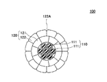
図1は、実施の形態の架空送電線100を示す斜視図である。図2は、実施の形態の架空送電線100を示す断面図である。図2に示す導体120の形状は扇形であるが、円形もしくは円形と扇形の組み合わせでもよい。図3は、図2に示す架空送電線100のコア110の断面を拡大して示す図である。
<Embodiment>
FIG. 1 is a perspective view showing an overhead
架空送電線100は、コア110と導体120を含む。図1には、架空送電線100の構成を分かり易くするために、2層構造の導体120をコア110に対して段階的に除去した状態を示す。
The overhead
コア110は、7本、19本など複数本のコアケーブル111を撚り合わせた構成を有する。たとえば、7本のコアケーブル111は、中心に位置する1本のコアケーブル111の周りに、6本のコアケーブル111を撚り合わせることによって作製される。
The
コアケーブル111は、コア線112と被覆部113とを有し(図3参照)、コア線112の外周を長手方向に沿って被覆部113で覆った構成を有する。コア線112は、カーボンコンポジット製であり、被覆部113はアルミニウム製である。なお、コア線のカーボンコンポジットの一部は、鋼としてもよい。
The
導体120は、コア110の外周を覆う導電線121と、導電線121の外周を覆う導電線122とを有する。導電線121は、コア110の外周に撚り合わされている。各導電線121は、螺旋状にコア110の外周に巻回されており、導電線121がコア110の外周を隙間なく覆っている。
The
また、導電線122は、導電線121の外周に撚り合わされている。各導電線122は、導電線121とは逆の巻き方で螺旋状に導電線121の外周に巻回されている。導電線122は、導電線121の外周を隙間なく覆っている。
Further, the
導電線121及び122は、ともに硬アルミニウム製である。硬アルミニウムとは、金属材料としてのアルミニウムそのものであり、硬アルミニウムを焼き鈍した軟アルミニウムとは異なる。
次に、図4乃至図14を用いて、実施の形態の第1実施例の架空送電線100について説明する。
Next, the overhead
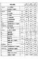
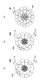
図4は、実施の形態の実施例1による架空送電線100A、100Bと、比較用の架空送電線10Aの断面構造を示す図である。図5は、実施の形態の実施例1による架空送電線100A、100Bと、比較用の架空送電線10Aの設計諸元を示す図である。
FIG. 4 is a diagram illustrating a cross-sectional structure of the overhead
架空送電線100Aと100Bは、導電線122の断面形状が異なる以外は、互いに同様の構成を有する。架空送電線100A及び100Bの導体120の断面積は、ともに209sqである。
Overhead
なお、架空送電線100Aの導電線122の角部の曲率半径r1、r2は1.2mmであり、架空送電線100Bの導電線122の角部の曲率半径r3、r4は、1.8mm、0.3mmである。角部に適切な曲率半径rを有することで、低風圧化を達成することが
できる。
The curvature radii r1 and r2 at the corners of the
比較用の架空送電線10Aは、ACSR/ACタイプの架空送電線であり、コア11Aと導体12Aを含む。ACSR(Aluminum Conductor Steel Reinforced)は、鋼心アルミニウム撚り線であることを意味し、導体12Aがアルミニウム製の撚線であることを表す。また、AC(Aluminum-clad steel wire)は、コア11Aの7本のコアケーブル1Aの各々が、鋼心をアルミニウムのクラッドで被覆したものであることを表す。コア11Aは、中央の1本のコアケーブル1Aの周りに6本のコアケーブル1Aを撚り合わせた構成を有する。
The comparative overhead
導体12Aの断面形状は円形であり、内側の12本の導体12Aと、外側の18本の導体12Aとの二層構造になっている。内側の12本の導体12Aは、コア11Aの外周に撚り合わされている。外側の18本の導体12Aは、内側の12本の導体12Aの外周に撚り合わわれている。
The cross-sectional shape of the
架空送電線100Aと100Bは、比較用の架空送電線10Aのコア11Aのコアケーブル1Aのコア線を鋼鉄製からカーボンコンポジット製に変更したものである。
The overhead
架空送電線100A及び100Bのコア110の線外径はφ7.8mm、コアケーブル111の外径はφ2.6mmである。コアケーブル111は、カーボンコンポジット製のコア線112(φ1.8mm)の周囲に、厚さ0.4mmのアルミニウム製の被覆部113を連続押し出しによって形成したものである。なお、アルミニウムの被覆厚さは、既存の製造設備において0.1mm〜0.6mmの範囲で調整できる。
The outer diameter of the
また、比較用の架空送電線10Aのコア11Aの線外径はφ7.8mmであり、コアケーブル1Aの外径はφ2.6mmである。コアケーブル1Aは導電率が20%(20AC)であり、直径φ2.26の鋼鉄製のコア線の周囲に、厚さ0.17mmのアルミニウム製の被覆部を連続押し出しによって形成したもものである。
Further, the outer diameter of the core 11A of the comparative
すなわち、架空送電線100Aと100Bのコア110のコアケーブル111の外径と、比較用の架空送電線10Aのコア11Aのコアケーブル1Aの外径とは等しい。
That is, the outer diameter of the
なお、図5におけるコアの面積比は、架空送電線100Aと100Bについては、架空送電線100Aと100Bの断面積(全面積A)に対するコア110の断面積(7本のコアケーブル111の合計の断面積As)の比である。また、比較用の架空送電線10Aについては、比較用の架空送電線10Aの断面積(全面積A)コア11Aの断面積(7本のコア11Aの合計の断面積As)の比である。
In addition, the area ratio of the core in FIG. 5 is the cross-sectional area of the core 110 (the total of the seven
全面積比ηは、比較用の架空送電線10Aについては、比較用の架空送電線10Aの断面積(全面積A)に対する、架空送電線100Aと100Bの断面積(全面積A)の比率である。
The total area ratio η is the ratio of the cross-sectional area of the overhead
また、架空送電線100Aと100Bは、比較用の架空送電線10Aの断面形状が円形の導体12Aを、断面形状が扇形の導体120に変更した構成を有する。
In addition, the overhead
このように、断面形状が円形の導体12Aから、断面形状が扇形の導体120に変更することにより、実施例1による架空送電線100A、100Bは、導体120の面積が拡大されている。
Thus, by changing the cross-sectional shape of the
上述したように、架空送電線100A及び100Bの導体120の断面積は、ともに209sqであり、これは、比較用の架空送電線10Aの導体12Aの断面積である160sqから約30%程度増大されている。
As described above, the cross-sectional areas of the
このようにして、架空送電線100A及び100Bは、比較用の架空送電線10Aに対して、伝送する電力の低損失化を図っている。
In this way, the overhead
なお、コア面積As、コア弾性係数Es、コア線膨張係数αs、直流電気抵抗R、直流電気抵抗比%、直流抵抗減100−Rr(DC)、最小引張荷重UTS、コア最小引張荷重UTS(ST)、電線重量W、電線重量比Wr、コア外径Ds、電線外径D、電線外径比Dr、電線温度tf、Rdc×β1、交流電気抵抗比、交流抵抗減、電流容量I、弛度d、弛度比drについては図5に示す通りである。 In addition, the core area As, the core elastic modulus Es, the core linear expansion coefficient αs, the DC electric resistance R, the DC electric resistance ratio%, the DC resistance reduction 100-Rr (DC), the minimum tensile load UTS, the core minimum tensile load UTS (ST ), Wire weight W, wire weight ratio Wr, core outer diameter Ds, wire outer diameter D, wire outer diameter ratio Dr, wire temperature tf, Rdc × β1, AC electrical resistance ratio, AC resistance reduction, current capacity I, sag d and the sag ratio dr are as shown in FIG.
また、全面積比ηは、架空送電線100A、100Bと架空送電線10Aの面積比であり、A(100A)/A(10A)、A(100B)/A(10A)で求まる。また、β1は表皮効果係数であり、交流電気抵抗比は、架空送電線100A、100BのRdc×β1と、比較用の架空送電線10AのRdc×β1との比である。
The total area ratio η is an area ratio between the overhead
比較用の架空送電線10Aの連続許容電流である484Aの電流を流したときの架空送電線100A及び100Bの交流抵抗減は27%であり、大幅な低ロス化が図られている。比較用の架空送電線10Aに連続許容電流である484Aの電流を流したときの電線温度は90℃であり、架空送電線100A及び100Bの電線温度は約80℃である。
The AC resistance reduction of the overhead
架空送電線100Aと比較用の架空送電線10Aを鉄塔間距離が400mの径間に架線して、連続許容電流484Aを流した場合には、架空送電線100Aの弛度は16.14mであり、比較用の架空送電線10Aの弛度は16.15mである。架空送電線100Aの弛度は、比較用の架空送電線10Aに対して同等以下となる。
When the overhead
架空送電線100A及び100Bのコア110のコアケーブル111の密度は2.18であるのに対して、比較用の架空送電線10Aのコア11Aのコアケーブル1Aの密度は6.53である。
The density of the
従って、架空送電線100A及び100Bは、比較用の架空送電線10Aに対して電線重量増を伴わずに、外径を若干大きくすることで、アルミニウム導体の断面積を160sq(導体12A)から209sq(導体120)まで増大させることができた。
Therefore, the overhead
なお、架空送電線100A及び100Bの外径はφ19mm、電線重量は0.6621kg/mである。一方、比較用の架空送電線10Aの外径はφ18.2mm、電線重量は0.6854kg/mである。
The overhead
図6は、実施の形態の実施例2による架空送電線100C、100Dと、比較用の架空送電線10Bの断面構造を示す図である。図7は、実施の形態の実施例2による架空送電線100C、100Dと、比較用の架空送電線10Bの設計諸元を示す図である。
FIG. 6 is a diagram illustrating a cross-sectional structure of the overhead
架空送電線100Cと100Dは、導電線122の断面形状が異なる以外は、互いに同様の構成を有する。架空送電線100C及び100Dの導体120の断面積は、527sqと528sqである。
Overhead
なお、架空送電線100Cの導電線122の角部の曲率半径r5、r6は、1.9mmであり、架空送電線100Bの導電線122の角部の曲率半径r7、r8は、3.0mm、0.3mmである。角部に適切な曲率半径rを有することで、低風圧化を達成することができる。
Note that the curvature radii r5 and r6 of the corners of the
比較用の架空送電線10Bは、ACSR/ACタイプの架空送電線であり、コア11Bと導体12Bを含む。
The comparative overhead
比較用の架空送電線10Bは、比較用の架空送電線10A(図4(C)参照)とは、サイズが異なるだけで構成は同様である。比較用の架空送電線10Bの導体12Bの断面積は410sqである。
The comparative overhead
架空送電線100Cと100Dは、比較用の架空送電線10Bのコア11Bのコアケーブル1Bのコア線を鋼鉄製からカーボンコンポジット製に変更したものである。
The overhead
架空送電線100C及び100Dのコア110の線外径はφ9.0mm、コアケーブル111の外径はφ3.0mmである。コアケーブル111は、カーボンコンポジット製のコア線112(φ2.2mm)の周囲に、厚さ0.4mmのアルミニウム製の被覆部113を連続押し出しによって形成したものである。
The
また、比較用の架空送電線10Bのコア11Bの線外径はφ10.5mmであり、コアケーブル1Bの外径はφ3.5mmである。
Further, the outer diameter of the core 11B of the comparative overhead
コアケーブル1Bは導電率が23%(23AC)であり、直径φ2.92の鋼鉄製のコア線の周囲に、厚さ0.29mmのアルミニウム製の被覆部を連続押し出しによって形成したものである。 The core cable 1B has a conductivity of 23% (23AC) and is formed by continuously extruding a 0.29 mm-thick aluminum covering portion around a steel core wire having a diameter of φ2.92.
なお、図7におけるコアの面積比は、架空送電線100Cと100Dについては、架空送電線100Cと100Dの断面積(全面積A)に対するコア110の断面積(7本のコアケーブル111の合計の断面積As)の比である。また、比較用の架空送電線10Bについては、比較用の架空送電線10Bの断面積(全面積A)コア11Bの断面積(7本のコア11Bの合計の断面積As)の比である。
In addition, the area ratio of the core in FIG. 7 is the cross-sectional area of the core 110 (the total of the seven
全面積比ηは、比較用の架空送電線10Bの断面積(全面積A)に対する、架空送電線100Cと100Dの断面積(全面積A)の比率である。
The total area ratio η is the ratio of the cross-sectional areas (total area A) of the overhead
また、架空送電線100Cと100Dは、比較用の架空送電線10Bの断面形状が円形の導体12Bを、断面形状が扇形の導体120に変更した構成を有する。
The overhead
このように、断面形状が円形の導体12Bから、断面形状が扇形の導体120に変更することにより、実施例2による架空送電線100C、100Dは、導体120の面積が拡大されており、導体120の断面積は527sqである。これは、比較用の架空送電線10Bの導体12Bの断面積である410sqから約30%程度増大されている。
Thus, by changing the cross-sectional shape of the
このようにして、架空送電線100C及び100Dは、比較用の架空送電線10Bに対して、伝送する電力の低損失化を図っている。比較用の架空送電線10Bの連続許容電流である871Aを流したときの、架空送電線100C及び100Dの交流抵抗減は20.8%であり、実施例1の架空送電線100A及び100Bと同様に大幅な低損失化が図られている。
In this way, the overhead
なお、コア面積As、コア弾性係数Es、コア線膨張係数αs、直流電気抵抗R、直流電気抵抗比%、直流抵抗減100−Rr(DC)、最小引張荷重UTS、コア最小引張荷重UTS(ST)、電線重量W、電線重量比Wr、コア外径Ds、電線外径D、電線外径比Dr、電線温度tf、Rdc×β1、交流電気抵抗比、交流抵抗減、電流容量I、弛度d、弛度比drについては図7に示す通りである。 In addition, the core area As, the core elastic modulus Es, the core linear expansion coefficient αs, the DC electric resistance R, the DC electric resistance ratio%, the DC resistance reduction 100-Rr (DC), the minimum tensile load UTS, the core minimum tensile load UTS (ST ), Wire weight W, wire weight ratio Wr, core outer diameter Ds, wire outer diameter D, wire outer diameter ratio Dr, wire temperature tf, Rdc × β1, AC electrical resistance ratio, AC resistance reduction, current capacity I, sag d and the sag ratio dr are as shown in FIG.
また、全面積比ηは、架空送電線100C、100Dと送電線10Bの面積比であり、A(100C)/A(10B)、A(100D)/A(10B)で求まる。また、β1は表皮効果係数であり、交流電気抵抗比は、架空送電線100A、100BのRdc×β1と、比較用の架空送電線10BのRdc×β1との比である。
The total area ratio η is an area ratio between the overhead
比較用の架空送電線10Bに連続許容電流である871Aの電流を流したときの電線温度は90℃であり、架空送電線100C及び100Dの電線温度は約83℃である。
The electric wire temperature when a current of 871A, which is a continuous allowable current, is passed through the comparative overhead
架空送電線100Cと比較用の架空送電線10Bを鉄塔間距離が400mの径間に架線して、連続許容電流871Aを流した場合には、架空送電線100Cの弛度は15.96mであり、比較用の架空送電線10Bの弛度は16.06mである。架空送電線100Cの弛度は、比較用の架空送電線10Bに対して同等以下となる。
When the overhead power transmission line 100C and the comparative overhead
架空送電線100C及び100Dのコア110のコアケーブル111の密度は2.12であるのに対して、比較用の架空送電線10Bのコア11Bのコアケーブル1Bの密度は6.27である。
The density of the
従って、架空送電線100C及び100Dは、比較用の架空送電線10Bに対して電線重量増を伴わずに、外径を若干大きくすることで、アルミニウム導体の断面積を410sq(導体12B)から527sq(導体120)まで増大させることができた。
Therefore, the overhead
なお、架空送電線100C及び100Dの外径はφ28.55mm、電線重量は1.566kg/mである。一方、比較用の架空送電線10Bの外径はφ28.5mm、電線重量は1.569kg/mである。
The overhead
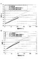
図8は、実施例1の架空送電線100Aと100Bで使用されるカーボンコンポジット製のコア線112(φ1.8mm)の応力−伸び特性を示す図である。なお、実測値は、カーボンコンポジット製のコア線112(φ1.8mm)に歪みゲージを取り付けて測定した。
FIG. 8 is a diagram showing the stress-elongation characteristics of the carbon composite core wire 112 (φ1.8 mm) used in the overhead
図8に示すように、カーボンコンポジット製のコア線112(φ1.8mm)の引張強さ実測値は2500MPa以上であり、伸び実測値は約2%である。このように、応力−伸び特性が示す弾性係数は設計値と略一致している。 As shown in FIG. 8, the measured tensile strength of the carbon composite core wire 112 (φ1.8 mm) is 2500 MPa or more, and the measured elongation is about 2%. As described above, the elastic modulus indicated by the stress-elongation characteristic is substantially coincident with the design value.
図9は、実施例1の架空送電線100Aと100Bで使用されるカーボンコンポジット製のコア線112(φ1.8mm)の引張強さヒストグラム(図9(A))とワイブルプロット(図9(B))を示す図である。ワイブルプロットによれば、累積確率1%での引張強さは2663MPaである。従って、実施例1の架空送電線100Aと100Bで使用されるカーボンコンポジット製のコア線112(φ1.8mm)の最小引張強さは2500MPa以上である。
FIG. 9 shows a tensile strength histogram (FIG. 9A) and a Weibull plot (FIG. 9B) of the core wire 112 (φ1.8 mm) made of carbon composite used in the overhead
図10は、実施例1の架空送電線100Aと100Bで使用される部材の曲げ特性を示す図である。図10には、実施例1の架空送電線100Aと100Bで使用されるカーボンコンポジット製のコア線112(φ1.8mm)と、コア110(φ7.8mm)との曲げ特性を示す。また、図10には、比較用に、1本のカーボンコンポジット(φ7.8mm)の曲げ特性を示す。
FIG. 10 is a diagram illustrating bending characteristics of members used in the overhead
1本のカーボンコンポジット(φ7.8mm)が曲げ破断に至る曲げ半径は200mmである。一方、コア線112(φ1.8mm)とコア110(φ7.8mm)が曲げ破断に至る半径はともに45mmである。コア110(φ7.8mm)は、7本撚り線にすることで、同一外径の1本のカーボンコンポジット(φ7.8mm)に比べて、許容曲げ半径を小さくすることができる。 The bending radius at which one carbon composite (φ7.8 mm) reaches bending fracture is 200 mm. On the other hand, the radius at which the core wire 112 (φ1.8 mm) and the core 110 (φ7.8 mm) are bent and fractured is 45 mm. The core 110 (φ7.8 mm) can be made to have an allowable bending radius smaller than that of one carbon composite (φ7.8 mm) having the same outer diameter by using seven stranded wires.
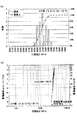
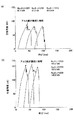
図11は、架空送電線100A(209sq)と架空送電線100C(527sq)の引張荷重チャートを示す図である。図11(A)には架空送電線100A(209sq)の引張荷重チャートを示し、図11(B)には架空送電線100C(527sq)の引張荷重チャートを示す。
FIG. 11 is a diagram illustrating a tensile load chart of the overhead
図11に示す引張荷重チャートでは、特異な変異点は認められず、引張荷重実測値は209sqの規格値71.6kN以上、527sqの規格値137kN以上を示している。その他、弾性係数、線膨張係数などの実測値は、すべて設計値どおりであった。 In the tensile load chart shown in FIG. 11, no specific variation point is recognized, and the actual tensile load value indicates a standard value of 209 sq of 71.6 kN or more, and a standard value of 527 sq of 137 kN or more. In addition, the measured values such as the elastic coefficient and the linear expansion coefficient were all as designed.
図12は、架空送電線100A(209sq)と架空送電線100C(527sq)の弛度特性を示す図である。図12(A)には架空送電線100A(209sq)の弛度特性を示し、図12(B)には架空送電線100C(527sq)の弛度特性を示す。なお、弛度試験時の電線温度実測値は、3本の熱電対の平均温度で示す。
FIG. 12 is a diagram illustrating the sag characteristics of the overhead
図12(A)及び(B)に示すように、架空送電線100A(209sq)と架空送電線100C(527sq)の弛度実測値は遷移点を考慮した計算値以下であり、良好な特性を示している。
As shown in FIGS. 12A and 12B, the measured sag values of the overhead
架空送電線100A(209sq)と架空送電線100C(527sq)は、比較用の架空送電線10A(160sq)及び10B(410sq)に対して低損失化を達成するために、外径が若干大きくなっている。
Overhead
架空送電線100A(209sq)の外径がφ19mmであるのに対して、比較用の架空送電線10A(160sq)の外径はφ18.2mmである。すなわち、架空送電線100A(209sq)の外径増加率は4.4%となる。
The outer diameter of the overhead
また、架空送電線100C(527sq)の外径がφ28.55mmであるのに対して、比較用の架空送電線10B(410sq)の外径はφ28.5mmである。架空送電線100C(527sq)の外径増加率は0.2%となる。
Further, the outer diameter of the overhead power transmission line 100C (527 sq) is φ28.55 mm, whereas the outer diameter of the comparative overhead
架空送電線の外径増加は風圧増加を伴うことから、架空送電線100A(209sq)と架空送電線100C(527sq)に低風圧化構造を採用した。
Since an increase in the outer diameter of the overhead power transmission line is accompanied by an increase in wind pressure, a low wind pressure structure is adopted for the overhead
なお、図4に示す架空送電線100Aについては、架空送電線100Aの導電線122の角部の曲率半径rは1.2mmであり、図6に示す架空送電線100Cでは、導電線122の角部の曲率半径rは1.9mmである。
4, the curvature radius r of the corner portion of the
図13は、架空送電線100A(209sq)と架空送電線100C(527sq)の風圧測定結果を示す図である。風速40m/sにおける架空送電線100A(209sq)の抗力係数CDは0.85であるのに対して、比較用の架空送電線10A(160sq)の抗力係数CDは0.92である。
FIG. 13 is a diagram illustrating wind pressure measurement results of the overhead
架空送電線100A(209sq)の架空送電線10A(160sq)に対する抗力係数CDの低減率は7.6%である。架空送電線100A(209sq)の外径増加率は4.4%であることから、抗力係数CDの低減率は外径増加率を上回り、鉄塔設計に影響を及ぼさないことになる。
The reduction rate of the drag coefficient CD of the overhead
また、風速40m/sにおける架空送電線100C(527sq)の抗力係数CDは0.73であり、比較用の架空送電線10B(410sq)の抗力係数CDは0.93である。架空送電線100C(527sq)の架空送電線10B(410sq)に対する抗力係数CDの低減率は22%である。
The drag coefficient CD of the overhead power transmission line 100C (527 sq) at a wind speed of 40 m / s is 0.73, and the drag coefficient CD of the comparative
架空送電線100C(527sq)の外径増加率は0.2%であることから、抗力係数CDの低減率は外径増加率を上回り、架空送電線100A(209sq)と同様に鉄塔設計に影響を及ぼさないことになる。
Since the outer diameter increase rate of the overhead power transmission line 100C (527sq) is 0.2%, the reduction rate of the drag coefficient CD exceeds the outer diameter increase rate and affects the tower design in the same way as the overhead
また、図13に示す架空送電線100A(209sq)及び架空送電線100C(527sq)相当の揚力係数CLは、風速に対する変動が小さく安定していることから、着雪なしで異常振動が発生する可能性はない。
Further, since the lift coefficient CL corresponding to the overhead
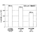
図14は、架空送電線100A(209sq)の10年間の二酸化炭素(CO2)排出量を示す図である。二酸化炭素(CO2)排出量の計算は、亘長(径間の水平距離)1km、電線6相分、送電線路の年平均負荷率40%、CO2排出係数0.3kg/kWhとして行った。
FIG. 14 is a diagram illustrating carbon dioxide (CO 2 ) emissions for 10 years from the overhead
架空送電線100A(209sq)の10年間での二酸化炭素(CO2)排出量は1260tonであり、比較用の架空送電線10A(160sq)の10年間での二酸化炭素(CO2)排出量は1730tonである。また、比較用の架空送電線10A(160sq)のコア11Aの7本のコアケーブル1Aにアルミニウム被覆を行わないACSR型の架空送電線(160sq)の10年間での二酸化炭素(CO2)排出量は1860tonである。
Carbon dioxide (CO 2) emissions in 10 years of
以上より、架空送電線100A(209sq)は、10年間での二酸化炭素(CO2)排出量について、コアケーブル1Aにアルミニウム被覆を行わない架空送電線(160sq)に対して600tonの削減が可能であり、比較用の架空送電線10A(160sq)に対して530tonの削減が可能となる。
As described above, the overhead
以上のように、実施の形態によれば、既存の製造設備及び製造管理方法で製造でき、強度の大幅な改善を図った架空送電線100A、100B、100C、100Dを提供することができる。
As described above, according to the embodiment, it is possible to provide the overhead
なお、以上では、架空送電線100A、100B、100C、100Dの低風圧化構造として、溝122Aが形成される角部の形状を有する形態について説明したが、低風圧化構造はこのような構造に限定されるものではなく、架空送電線100A、100B、100C、100Dの表面に凹部及び/又は凸部を設けることによって風圧を低減できる構造であれば、他の如何なる構造であってもよい。
In addition, although the form which has the shape of the corner | angular part in which the groove |
以上、本発明の例示的な実施の形態の架空送電線について説明したが、本発明は、具体的に開示された実施の形態に限定されるものではなく、特許請求の範囲から逸脱することなく、種々の変形や変更が可能である。 The overhead power transmission line of the exemplary embodiment of the present invention has been described above, but the present invention is not limited to the specifically disclosed embodiment, and does not depart from the scope of the claims. Various modifications and changes are possible.
100A、100B、100C、100D 架空送電線
110 コア
111 コアケーブル
112 コア線
113 被覆部
120 導体
121 導電線
122 導電線
122A 溝
100A, 100B, 100C, 100D Overhead
Claims (3)
Priority Applications (2)
| Application Number | Priority Date | Filing Date | Title |
|---|---|---|---|
| JP2014123411A JP6240030B2 (en) | 2014-06-16 | 2014-06-16 | Overhead power line |
| PCT/JP2015/058642 WO2015194221A1 (en) | 2014-06-16 | 2015-03-16 | Overhead transmission conductor |
Applications Claiming Priority (1)
| Application Number | Priority Date | Filing Date | Title |
|---|---|---|---|
| JP2014123411A JP6240030B2 (en) | 2014-06-16 | 2014-06-16 | Overhead power line |
Publications (2)
| Publication Number | Publication Date |
|---|---|
| JP2016004654A true JP2016004654A (en) | 2016-01-12 |
| JP6240030B2 JP6240030B2 (en) | 2017-11-29 |
Family
ID=54935218
Family Applications (1)
| Application Number | Title | Priority Date | Filing Date |
|---|---|---|---|
| JP2014123411A Active JP6240030B2 (en) | 2014-06-16 | 2014-06-16 | Overhead power line |
Country Status (2)
| Country | Link |
|---|---|
| JP (1) | JP6240030B2 (en) |
| WO (1) | WO2015194221A1 (en) |
Cited By (3)
| Publication number | Priority date | Publication date | Assignee | Title |
|---|---|---|---|---|
| CN106128561A (en) * | 2016-08-31 | 2016-11-16 | 无锡江南电缆有限公司 | A kind of trapezoidal heat resisting diameter enlarging bus bar of modified model |
| JP2020515726A (en) * | 2017-01-27 | 2020-05-28 | ファツアー・アーゲー・ドラートザイルファブリック | Longitudinal elements especially for traction or suspension means |
| JP7279250B1 (en) * | 2022-10-31 | 2023-05-22 | 東京製綱株式会社 | Fiber-reinforced resin cable and wire with damage detection function |
Families Citing this family (4)
| Publication number | Priority date | Publication date | Assignee | Title |
|---|---|---|---|---|
| CN106941021B (en) * | 2017-03-17 | 2019-05-31 | 远东电缆有限公司 | A kind of composite core, compound wire and production technology |
| CN107833662A (en) * | 2017-10-20 | 2018-03-23 | 南方电网科学研究院有限责任公司 | Stranded carbon fiber windproof lead |
| FR3076944B1 (en) * | 2018-01-16 | 2020-12-18 | Nexans | HIGH VOLTAGE ELECTRICAL ENERGY TRANSMISSION CONDUCTOR |
| EA202091770A1 (en) * | 2018-01-24 | 2020-10-16 | СиТиСи ГЛОБАЛ КОРПОРЕЙШН | TERMINAL DEVICE FOR AIR ELECTRIC CABLE |
Citations (5)
| Publication number | Priority date | Publication date | Assignee | Title |
|---|---|---|---|---|
| JPH04308610A (en) * | 1991-04-04 | 1992-10-30 | Tokyo Electric Power Co Inc:The | Overhead transmission line |
| JP2001291429A (en) * | 2000-04-07 | 2001-10-19 | Furukawa Electric Co Ltd:The | Overhead power line and optical fiber composite overhead earth-wire |
| US20040182597A1 (en) * | 2003-03-20 | 2004-09-23 | Smith Jack B. | Carbon-core transmission cable |
| JP2007521968A (en) * | 2004-02-13 | 2007-08-09 | スリーエム イノベイティブ プロパティズ カンパニー | Method for manufacturing metal-cladded metal matrix composite wire |
| EP1821318A2 (en) * | 2006-02-17 | 2007-08-22 | De Angeli Prodotti S.r.l. | conductor cable for electrical lines |
-
2014
- 2014-06-16 JP JP2014123411A patent/JP6240030B2/en active Active
-
2015
- 2015-03-16 WO PCT/JP2015/058642 patent/WO2015194221A1/en active Application Filing
Patent Citations (5)
| Publication number | Priority date | Publication date | Assignee | Title |
|---|---|---|---|---|
| JPH04308610A (en) * | 1991-04-04 | 1992-10-30 | Tokyo Electric Power Co Inc:The | Overhead transmission line |
| JP2001291429A (en) * | 2000-04-07 | 2001-10-19 | Furukawa Electric Co Ltd:The | Overhead power line and optical fiber composite overhead earth-wire |
| US20040182597A1 (en) * | 2003-03-20 | 2004-09-23 | Smith Jack B. | Carbon-core transmission cable |
| JP2007521968A (en) * | 2004-02-13 | 2007-08-09 | スリーエム イノベイティブ プロパティズ カンパニー | Method for manufacturing metal-cladded metal matrix composite wire |
| EP1821318A2 (en) * | 2006-02-17 | 2007-08-22 | De Angeli Prodotti S.r.l. | conductor cable for electrical lines |
Cited By (3)
| Publication number | Priority date | Publication date | Assignee | Title |
|---|---|---|---|---|
| CN106128561A (en) * | 2016-08-31 | 2016-11-16 | 无锡江南电缆有限公司 | A kind of trapezoidal heat resisting diameter enlarging bus bar of modified model |
| JP2020515726A (en) * | 2017-01-27 | 2020-05-28 | ファツアー・アーゲー・ドラートザイルファブリック | Longitudinal elements especially for traction or suspension means |
| JP7279250B1 (en) * | 2022-10-31 | 2023-05-22 | 東京製綱株式会社 | Fiber-reinforced resin cable and wire with damage detection function |
Also Published As
| Publication number | Publication date |
|---|---|
| JP6240030B2 (en) | 2017-11-29 |
| WO2015194221A1 (en) | 2015-12-23 |
Similar Documents
| Publication | Publication Date | Title |
|---|---|---|
| JP6240030B2 (en) | Overhead power line | |
| USRE49941E1 (en) | Rating an enhanced strength conductor | |
| US9490050B2 (en) | Hybrid conductor core | |
| CN101807453B (en) | Power cable for seabed | |
| CN104134483B (en) | A kind of strand type carbon fiber complex core soft aluminum conductor and preparation method thereof | |
| RU161777U1 (en) | RAILWAY CONTACT NETWORK ROPE | |
| US20110100677A1 (en) | Fiber-polymer composite | |
| Thrash | Transmission conductors–A review of the design and selection criteria | |
| RU171205U1 (en) | Bearing reinforced cable of the contact network of the railway | |
| JP2007305479A (en) | Electric cable | |
| RU2619090C1 (en) | Non-isolated cable (versions) | |
| CN201655376U (en) | High-tensile wear-resistant mobile rubber sleeve cable | |
| RU136913U1 (en) | SELF-SUPPORTING WIRE ISOLATED AND PROTECTED | |
| RU127239U1 (en) | DARK-PROTECTED CABLE (OPTIONS) | |
| RU119513U1 (en) | STEEL WIRE FOR ELECTRIC TRANSMISSION AIR LINE (OPTIONS) | |
| CN104616786A (en) | Composite core high stretching rate heat resisting aluminum alloy conductor for smart energy source and manufacture method thereof | |
| RU132241U1 (en) | STEEL ALUMINUM WIRE FOR ELECTRIC TRANSMISSION AIRLINE | |
| CN103354114A (en) | Carbon fiber copper core alloy wire spiral wrapping cable | |
| JP2010062030A (en) | Overhead transmission line | |
| JP2014002863A (en) | Steel core aluminum stranded wire and method for manufacturing the same | |
| RU202337U1 (en) | Bare wire | |
| RU204447U1 (en) | Small-sized submersible load-carrying cable | |
| RU183393U1 (en) | Uninsulated wire | |
| CN202422790U (en) | Shielded high flexible cable | |
| RU182153U1 (en) | Uninsulated wire |
Legal Events
| Date | Code | Title | Description |
|---|---|---|---|
| A711 | Notification of change in applicant |
Free format text: JAPANESE INTERMEDIATE CODE: A712 Effective date: 20160218 |
|
| A621 | Written request for application examination |
Free format text: JAPANESE INTERMEDIATE CODE: A621 Effective date: 20160719 |
|
| A131 | Notification of reasons for refusal |
Free format text: JAPANESE INTERMEDIATE CODE: A131 Effective date: 20170815 |
|
| A521 | Request for written amendment filed |
Free format text: JAPANESE INTERMEDIATE CODE: A523 Effective date: 20171004 |
|
| TRDD | Decision of grant or rejection written | ||
| A01 | Written decision to grant a patent or to grant a registration (utility model) |
Free format text: JAPANESE INTERMEDIATE CODE: A01 Effective date: 20171017 |
|
| A61 | First payment of annual fees (during grant procedure) |
Free format text: JAPANESE INTERMEDIATE CODE: A61 Effective date: 20171102 |
|
| R150 | Certificate of patent or registration of utility model |
Ref document number: 6240030 Country of ref document: JP Free format text: JAPANESE INTERMEDIATE CODE: R150 |
|
| R250 | Receipt of annual fees |
Free format text: JAPANESE INTERMEDIATE CODE: R250 |
|
| R250 | Receipt of annual fees |
Free format text: JAPANESE INTERMEDIATE CODE: R250 |
|
| R250 | Receipt of annual fees |
Free format text: JAPANESE INTERMEDIATE CODE: R250 |
|
| R250 | Receipt of annual fees |
Free format text: JAPANESE INTERMEDIATE CODE: R250 |