JP2016000623A - Outer sleeve for thermal insulation and thermo-insulating paper container - Google Patents
Outer sleeve for thermal insulation and thermo-insulating paper container Download PDFInfo
- Publication number
- JP2016000623A JP2016000623A JP2014121921A JP2014121921A JP2016000623A JP 2016000623 A JP2016000623 A JP 2016000623A JP 2014121921 A JP2014121921 A JP 2014121921A JP 2014121921 A JP2014121921 A JP 2014121921A JP 2016000623 A JP2016000623 A JP 2016000623A
- Authority
- JP
- Japan
- Prior art keywords
- outer sleeve
- paper container
- height
- emboss
- paper
- Prior art date
- Legal status (The legal status is an assumption and is not a legal conclusion. Google has not performed a legal analysis and makes no representation as to the accuracy of the status listed.)
- Pending
Links
Images


Classifications
-
- B—PERFORMING OPERATIONS; TRANSPORTING
- B65—CONVEYING; PACKING; STORING; HANDLING THIN OR FILAMENTARY MATERIAL
- B65D—CONTAINERS FOR STORAGE OR TRANSPORT OF ARTICLES OR MATERIALS, e.g. BAGS, BARRELS, BOTTLES, BOXES, CANS, CARTONS, CRATES, DRUMS, JARS, TANKS, HOPPERS, FORWARDING CONTAINERS; ACCESSORIES, CLOSURES, OR FITTINGS THEREFOR; PACKAGING ELEMENTS; PACKAGES
- B65D3/00—Rigid or semi-rigid containers having bodies or peripheral walls of curved or partially-curved cross-section made by winding or bending paper without folding along defined lines
- B65D3/02—Rigid or semi-rigid containers having bodies or peripheral walls of curved or partially-curved cross-section made by winding or bending paper without folding along defined lines characterised by shape
- B65D3/06—Rigid or semi-rigid containers having bodies or peripheral walls of curved or partially-curved cross-section made by winding or bending paper without folding along defined lines characterised by shape essentially conical or frusto-conical
-
- B—PERFORMING OPERATIONS; TRANSPORTING
- B65—CONVEYING; PACKING; STORING; HANDLING THIN OR FILAMENTARY MATERIAL
- B65D—CONTAINERS FOR STORAGE OR TRANSPORT OF ARTICLES OR MATERIALS, e.g. BAGS, BARRELS, BOTTLES, BOXES, CANS, CARTONS, CRATES, DRUMS, JARS, TANKS, HOPPERS, FORWARDING CONTAINERS; ACCESSORIES, CLOSURES, OR FITTINGS THEREFOR; PACKAGING ELEMENTS; PACKAGES
- B65D25/00—Details of other kinds or types of rigid or semi-rigid containers
- B65D25/34—Coverings or external coatings
- B65D25/36—Coverings or external coatings formed by applying sheet material
-
- B—PERFORMING OPERATIONS; TRANSPORTING
- B65—CONVEYING; PACKING; STORING; HANDLING THIN OR FILAMENTARY MATERIAL
- B65D—CONTAINERS FOR STORAGE OR TRANSPORT OF ARTICLES OR MATERIALS, e.g. BAGS, BARRELS, BOTTLES, BOXES, CANS, CARTONS, CRATES, DRUMS, JARS, TANKS, HOPPERS, FORWARDING CONTAINERS; ACCESSORIES, CLOSURES, OR FITTINGS THEREFOR; PACKAGING ELEMENTS; PACKAGES
- B65D3/00—Rigid or semi-rigid containers having bodies or peripheral walls of curved or partially-curved cross-section made by winding or bending paper without folding along defined lines
- B65D3/22—Rigid or semi-rigid containers having bodies or peripheral walls of curved or partially-curved cross-section made by winding or bending paper without folding along defined lines with double walls; with walls incorporating air-chambers; with walls made of laminated material
-
- B—PERFORMING OPERATIONS; TRANSPORTING
- B65—CONVEYING; PACKING; STORING; HANDLING THIN OR FILAMENTARY MATERIAL
- B65D—CONTAINERS FOR STORAGE OR TRANSPORT OF ARTICLES OR MATERIALS, e.g. BAGS, BARRELS, BOTTLES, BOXES, CANS, CARTONS, CRATES, DRUMS, JARS, TANKS, HOPPERS, FORWARDING CONTAINERS; ACCESSORIES, CLOSURES, OR FITTINGS THEREFOR; PACKAGING ELEMENTS; PACKAGES
- B65D81/00—Containers, packaging elements, or packages, for contents presenting particular transport or storage problems, or adapted to be used for non-packaging purposes after removal of contents
- B65D81/38—Containers, packaging elements, or packages, for contents presenting particular transport or storage problems, or adapted to be used for non-packaging purposes after removal of contents with thermal insulation
Landscapes
- Engineering & Computer Science (AREA)
- Mechanical Engineering (AREA)
- Packages (AREA)
- Details Of Rigid Or Semi-Rigid Containers (AREA)
Abstract
Description
本発明は、エンボスを形成した断熱用外スリーブおよびその断熱用外スリーブを設けた断熱性紙容器に関するものである。 The present invention relates to a heat insulating outer sleeve formed with an emboss and a heat insulating paper container provided with the heat insulating outer sleeve.
従来、カップ状の紙容器に断熱性を付与するために紙容器本体の側壁部の外面にエンボス加工した外スリーブを巻きつけた断熱性容器が知られている。
例えば、実用新案登録第2583258号や実用新案登録第2603108号の断熱性紙カップでは、円錐台形状の紙カップ側壁部外周に、高低差が1〜2mmの同一深度にて、直径が2〜5mmの点状の凸部もしくは凹部のエンボス模様、または凸部と凹部を交互に配したエンボス模様を3個/cm2〜10個/cm2の密度で施した紙製の断熱性シートが巻付けられ、該断熱性シートの点状のエンボス模様の密度が巻付け端部を含めて略同一密度を以て略連続性のある外観を呈している構成が開示されている。
しかし、外スリーブのブランクは扇形をしているので、エンボスの凸部や凹部がほぼ同一形状の場合に、ブランクを筒状に巻き付ける方向におけるエンボスの数は外スリーブの上下で異なり、巻き付け方向における剛性が上下で異なるので、紙カップに外スリーブを巻き付けられない場合が生じる。
その原因としては、巻き付け方向における剛度が前記ブランクの上下で異なるため、その差が一定以上大きいと上下を巻き付け方向に均等に湾曲させることが困難となって、巻き付けできなくなることが判明した。
2. Description of the Related Art Conventionally, a heat insulating container is known in which an embossed outer sleeve is wound around the outer surface of a side wall portion of a paper container main body in order to impart heat insulation to a cup-shaped paper container.
For example, in the heat insulating paper cup of utility model registration No. 2583258 and utility model registration No. 2603108, the point of the diameter of 2 to 5 mm at the same depth of 1 to 2 mm in height difference on the outer periphery of the frustoconical paper cup side wall. Jo embossed pattern of the convex portions or concave portions or convex portions and three of the embossed pattern which arranged alternately concave /
However, since the blank of the outer sleeve has a fan shape, the number of embossments in the direction of winding the blank in a cylindrical shape differs depending on the upper and lower sides of the outer sleeve when the convex and concave portions of the emboss are substantially the same shape. Since the rigidity is different between the upper and lower sides, the outer sleeve may not be wound around the paper cup.
As the cause, since the rigidity in the winding direction is different between the upper and lower sides of the blank, it has been found that if the difference is larger than a certain level, it is difficult to bend the upper and lower sides evenly in the winding direction and the winding cannot be performed.
また、断熱性容器をスタッキングした際に取り外しが容易になるよう、ブロッキングを抑制する為にカップの上端のカール部側から底部側に向けて、順次、少しずつエンボスの高低差を低くしたり、外形を小さくしたりする構成も知られているが、この場合もエンボスを深く(大きく)入れた部分は横方向の剛度が大きくなり、エンボスが低い(小さい)部分との間で剛度の差が発生するので、その差が一定以上大きいと上下を巻き付け方向に均等に湾曲させることが困難となり、巻き付けできなくなる。
更に、外スリーブの上下でエンボスの高低差が異なるということは、1枚の外スリーブの中で厚みが異なり、径差が大きくなることから巻くことが難しくなる。
これらに対して、外スリーブの巻き付け方法を工夫したり、巻付け速度を落として巻き付ける方法が考えられるが、上記方法では巻付け装置の構造が複雑になることや、生産性が低下するという不具合がある。
そこで、本発明者らは鋭意研究の結果、エンボス加工した外スリーブの紙容器本体への巻き付けの可否は、外スリーブの巻き付け方向の剛度が密接に関係していることを見い出し、また高さが順次低くなるエンボスの場合は、更に最大高さと最小高さの比も関係することを見いだし、本発明を完成するに至った。
In addition, in order to suppress blocking when stacking the heat insulating container, in order to suppress blocking, from the curl side to the bottom side of the upper end of the cup, the height difference of the emboss is gradually reduced, There are also known configurations that make the outer shape smaller, but in this case too, the embossed part is deeper (larger) and the rigidity in the lateral direction increases, and the difference in rigidity between the part with lower (smaller) embossing is different. Therefore, if the difference is larger than a certain level, it becomes difficult to bend the top and bottom evenly in the winding direction, and winding becomes impossible.
Further, the difference in the height of the embossment between the upper and lower sides of the outer sleeve means that the thickness is different in one outer sleeve and the diameter difference becomes large, so that it is difficult to wind.
On the other hand, the method of winding the outer sleeve can be devised, or the method of winding at a lower winding speed can be considered, but with the above method the structure of the winding device is complicated and the productivity is reduced. There is.
Therefore, as a result of earnest research, the present inventors have found that the rigidity of the winding direction of the outer sleeve is closely related to whether or not the embossed outer sleeve can be wound around the paper container main body, and the height is high. In the case of embossing that gradually decreases, it has been found that the ratio between the maximum height and the minimum height is also related, and the present invention has been completed.
この発明は上記不具合を解決するために創案されたものであって、その主たる課題は、外スリーブに形成されるエンボスの巻き付け方向における最大剛度と最小剛度を一定範囲に限定することで、前記外スリーブを紙容器本体に容易に巻きつけることができる断熱用外スリーブおよびそれを用いた断熱性紙容器を提供することにある。
この発明の別の課題は、
外スリーブのエンボスの高低差を上から下に向かって漸次低くする構成を採る場合でも、紙容器本体に外スリーブを容易に巻きつけることができる断熱用外スリーブおよびそれを用いた断熱性紙容器を提供することにある。
The present invention has been devised to solve the above problems, and the main problem is that the maximum stiffness and the minimum stiffness in the winding direction of the emboss formed on the outer sleeve are limited to a certain range, thereby An object of the present invention is to provide an outer sleeve for heat insulation in which a sleeve can be easily wound around a paper container body and a heat insulating paper container using the same.
Another subject of this invention is
Even when adopting a configuration in which the height difference of the embossment of the outer sleeve is gradually lowered from the top to the bottom, the outer sleeve for heat insulation that can easily wind the outer sleeve around the paper container body and the heat insulating paper container using the same Is to provide.
この発明は、上記課題を解決するために、請求項1の発明では、
円錐台形状の紙容器本体の胴部の外周に沿って巻き付ける紙製外スリーブであって、縦横に連続する多数の凹凸からなるエンボスが施された断熱用外スリーブにおいて、
断熱性外スリーブに形成されるエンボスの巻き付け方向における最大剛度(S1)が14.5mN・m以下であり、かつ最大剛度と最小剛度(S2)の比であるS1/S2が1≦S1/S2≦1.89の条件を満たすことを特徴とする。
請求項2の発明では、
前記 断熱性外スリーブに形成されるエンボスは、紙容器本体装着時の上から下に向かってエンボスの高さが漸次低く設定されていることを特徴とする。
請求項3の発明では、
外スリーブに形成されるエンボスの最も高い部分のエンボス高さ(H1)と、最も低い部分のエンボス高さ(H2)の比であるH1/H2が、1.00以上で3.78以下の条件を満たすことを特徴とする。
請求項4の断熱性紙容器の発明では、
上記請求項1または2に記載の断熱用外スリーブを円錐台形状の紙容器本体の胴部の外周に巻き付けてなることを特徴とする。
In order to solve the above-mentioned problems, the present invention provides
A paper outer sleeve that is wound around the outer periphery of the body of the truncated cone-shaped paper container body, and is an outer sleeve for heat insulation that has been embossed with a number of concavities and convexities that are continuous vertically and horizontally.
The maximum stiffness (S1) in the winding direction of the emboss formed on the heat-insulating outer sleeve is 14.5 mN · m or less, and the ratio of the maximum stiffness to the minimum stiffness (S2) S1 / S2 is 1 ≦ S1 / S2. ≦ 1.89 is satisfied.
In the invention of
The embossing formed on the heat insulating outer sleeve is characterized in that the height of the embossing is set gradually lower from the top to the bottom when the paper container body is mounted.
In the invention of
H1 / H2, which is the ratio of the emboss height (H1) of the highest embossed portion formed on the outer sleeve to the emboss height (H2) of the lowest portion, is 1.00 or more and 3.78 or less It is characterized by satisfying.
In the invention of the heat insulating paper container of
The outer sleeve for heat insulation according to claim 1 or 2 is wound around the outer periphery of the trunk portion of the paper container body having a truncated cone shape.
この発明の断熱性紙容器は、外スリーブのエンボスの最大剛度(S1)と最小剛度(S2)が一定以下であって、かつ、最大剛度(S1)と最小剛度(S2)の比が一定以下であると、外スリーブを紙容器本体に容易に巻き付けることができる。
また、最も高い部分のエンボス高さ(H1)と、最も低い部分のエンボス高さ(H2)の比が一定以下であると、外スリーブを紙容器本体に容易に巻き付けることができる。
In the heat insulating paper container of the present invention, the maximum stiffness (S1) and the minimum stiffness (S2) of the embossing of the outer sleeve are not more than a certain value, and the ratio of the maximum stiffness (S1) and the minimum stiffness (S2) is not more than a certain value. In this case, the outer sleeve can be easily wound around the paper container body.
Further, when the ratio of the emboss height (H1) at the highest portion to the emboss height (H2) at the lowest portion is equal to or less than a certain value, the outer sleeve can be easily wound around the paper container body.
この発明は、エンボスの凹凸の剛性が一定の範囲であって、上下のエンボスの最大剛性と最小剛度の比が一定の条件となるようにエンボスを成形し、またエンボスの上下の最大高さと最小高さの比が一定の条件となるようにエンボスを成形することで、外スリーブを紙容器本体に確実に巻き付けることを実現した。
以下にこの発明の好適実施例について図面を参照しながら説明する。
In the present invention, the emboss is formed so that the rigidity of the embossed unevenness is in a certain range, and the ratio of the maximum stiffness and the minimum stiffness of the upper and lower embosses is a constant condition. By forming the embossment so that the height ratio is constant, the outer sleeve is securely wound around the paper container body.
Hereinafter, preferred embodiments of the present invention will be described with reference to the drawings.
以下にこの発明の好適実施例について図面を参照しながら説明する。
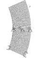
図1に示す断熱性紙容器1は、公知の有底の円錐台形状の紙容器本体2と、該紙容器本体2の胴部3に巻き付けられて固着された断熱用外スリーブ5とからなっている。
断熱用外スリーブ5のブランクは、略扇状からなってエンボスの凸部6が等間隔に多数形成されており、紙カップ本体1に巻き付けられる。
Hereinafter, preferred embodiments of the present invention will be described with reference to the drawings.
A heat insulating paper container 1 shown in FIG. 1 includes a known bottomed truncated cone-shaped paper container
The blank of the heat insulating
即ち、断熱用外スリーブ5の上端部5aは、紙容器本体2のカール部2aより下側で紙カップ本体1の胴部に略隙間なくスリーブ状に巻付けられる。
断熱用外スリーブ5の上端にはエンボスを形成せずにカール部2aに巻き込んで固着してもよい。
That is, the
The upper end of the heat insulating
前記エンボスは、その凸部6の内側と、紙カップ本体1の胴部3の外壁との間に空間部4が形成されて断熱機能を有する。
なお、前記断熱用外スリーブ5は、その表面に適宜に印刷などにより文字や絵柄、彩色などを施したものを使用してもよい。
The embossing has a
The heat insulating
上記エンボスの凸部6が連続して形成される外スリーブ5にあっては、紙容器本体2への巻き付け方向におけるエンボスの剛度やエンボスの凸部6の高さによって、紙容器本体2の胴部3の外周面に沿って巻き付けることができない場合があり、エンボスの巻き付け方向の剛性や、エンボスの凸部の高さに一定の条件が必要となる。
In the
[測定データ1]
前記外スリーブ5のブランクに対応した扇形状のテスト原紙5’にエンボスの凸部6の高さが段階的に順次低くなるようにエンボス加工し(図2(a)参照)、そのエンボス加工したテスト原紙5’が紙容器本体2の胴部3へ巻き付け可能か否かをテストした。
エンボスの凸部6の高い箇所S1と低い箇所S2(図2(b)参照)での剛度を測定し、剛度と巻き付けの可否を以下の条件にて測定した。
[Measurement data 1]
The fan-shaped
Stiffness was measured at high places S1 and low places S2 (see FIG. 2 (b)) of the embossed
テスト原紙5’として、エンボス加工に最適なものとして原紙A、エンボス加工に一般に用いられるものとして原紙B、C、その他のものとして原紙Dを用いた。
原紙A:a社製原紙 200g/m2(坪量、以下同じ)
原紙B:b社製原紙 200g/m2
原紙C:b社製原紙 300g/m2
原紙D:c社製原紙 420g/m2
As test base paper 5 ', base paper A was used as the most suitable for embossing, base papers B and C were used generally for embossing, and base paper D was used as the other.
Base paper A: Base paper manufactured by company a 200 g / m 2 (basis weight, the same applies hereinafter)
Base paper B: Base paper manufactured by company b 200 g / m 2
Base paper C: Base paper manufactured by company b 300 g / m 2
Base paper D: Base paper made by company c 420 g / m 2
原紙A〜Dのテスト原紙5’は紙コップや紙カップに巻き付けられるような扇形状に打ち抜かれている。
エンボス加工は、エンボス加工装置で、原紙の流れ方向にエンボス高さが低くなるように 扇形状の全体をエンボス加工した。
即ち、エンボスは、図1の場合は、径方向(行方向)の同一線上に多数の凸部6を僅かな間隔を隔てて等間隔に配置しており、該行方向の凸部の列を等しい角度で多数列配置した構成からなっており、上下左右に隣接した4つの凸部6の間に凹部7が形成されるように千鳥配列で形成されている。
また、図4に示すエンボスでは、凸部6を縦横に並べて配置し、凸部7の行方向および列方向を仕切る隙間(凹部に相当する)がそれぞれ同一の幅となる直線または曲線となるように設定されている。
本発明では、凸部と凹部、または凸部の組み合わせは上記図示例に限定されず、断熱用の一定のパターンで配置されていればよい。
The test base paper 5 'of the base papers A to D is punched into a fan shape that can be wound around a paper cup or paper cup.
For embossing, the whole fan shape was embossed with an embossing device so that the embossing height was low in the flow direction of the base paper.
That is, in the case of FIG. 1, the embossing has a large number of
In the embossing shown in FIG. 4, the
In this invention, the combination of a convex part and a recessed part or a convex part is not limited to the said example of illustration, What is necessary is just to arrange | position with the fixed pattern for heat insulation.
エンボス加工は、凹版と凸版のエンボスロールの間にブランクを通す方法、プレート状の凸版と凹版をブランクの上下からプレスする方法、ブランクの上下から凸版と凹版を千鳥配列にして加圧する方法など公知の方法を用いることができる。
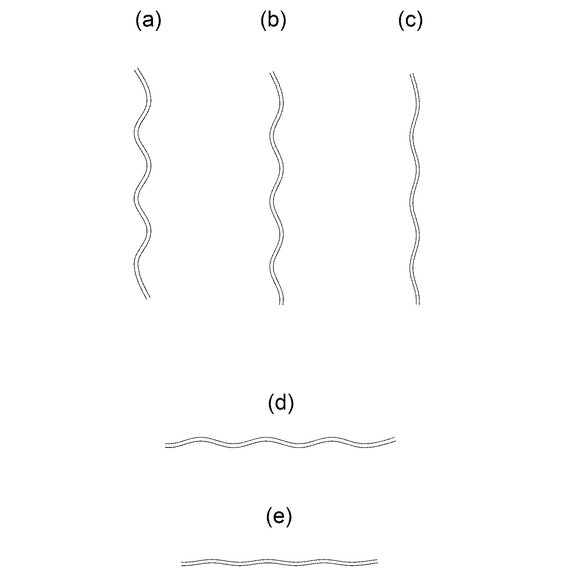
図4の外スリーブに形成されたエンボスは、縦方向における上部(a−a)・中間(b−b)・下部(c−c)の3個所の縦端面(図5(a)〜(c)参照)と、横方向(巻き付け方向)における上部(d−d)・下部(e−e)の2個所の横端面図(図5(d)〜(e)参照)を示している。
For embossing, a method of passing a blank between an intaglio and a relief embossing roll, a method of pressing a plate-like relief and an intaglio from above and below the blank, and a method of pressurizing the relief and intaglio in a staggered arrangement from above and below the blank This method can be used.
The embosses formed on the outer sleeve of FIG. 4 have three vertical end faces (FIGS. 5A to 5C) in the upper part (aa), middle (bb), and lower part (cc) in the vertical direction. )) And two lateral end views (see FIGS. 5D to 5E) of the upper part (dd) and the lower part (ee) in the lateral direction (winding direction).
図1のエンボス形状は、例えば、意匠登録第1174242号などと同様の形状であり、この場合の断面も前記図5の端面図に準じる。
この発明のエンボスの凸部6の平面的な形状は、丸点状、四角点状、六角点状など適宜な形状であってもよい。
ここでエンボスの一例を挙げると、凸部と凹部(凸部と凸部の間)を交互に3個/cm2〜10個/cm2の密度に配置し、凸部の直径を2mm〜5mmとしたが、この発明では上記数値に限定されないこと勿論である。
The embossed shape in FIG. 1 is the same shape as, for example, Design Registration No. 1174242, and the cross section in this case also conforms to the end view of FIG.
The planar shape of the embossed
As an example of embossing, convex portions and concave portions (between convex portions and convex portions) are alternately arranged at a density of 3 pieces / cm 2 to 10 pieces / cm 2 , and the diameter of the convex portions is 2 mm to 5 mm. Of course, the present invention is not limited to the above numerical values.
各テスト原紙A〜Dは、実用品で使用する範囲でエンボス加工量(凸部の高さ)をそれぞれ3種類に調整した。
(単位mm)
原紙A1 エンボスの最上高さ0.87 最小高さ0.57
A2 エンボスの最上高さ0.87 最小高さ0.46
A3 エンボスの最上高さ0.87 最小高さ0.23
原紙B1 エンボスの最上高さ0.96 最小高さ0.64
B2 エンボスの最上高さ0.87 最小高さ0.57
B3 エンボスの最上高さ0.87 最小高さ0.24
原紙C1 エンボスの最上高さ1.10 最小高さ0.75
C2 エンボスの最上高さ1.10 最小高さ0.67
C3 エンボスの最上高さ1.10 最小高さ0.34
原紙D1 エンボスの最上高さ1.47 最小高さ1.27
D2 エンボスの最上高さ1.47 最小高さ1.14
D3 エンボスの最上高さ1.10 最小高さ0.59
Each of the test base papers A to D was adjusted to three types of embossing amounts (heights of the convex portions) within a range used in a practical product.
(Unit: mm)
Base paper A1 Emboss top height 0.87 Minimum height 0.57
A2 Emboss top height 0.87 Minimum height 0.46
A3 Emboss top height 0.87 Minimum height 0.23
Base paper B1 Emboss top height 0.96 Minimum height 0.64
B2 Emboss top height 0.87 Minimum height 0.57
B3 Emboss top height 0.87 Minimum height 0.24
Base paper C1 Emboss top height 1.10 Minimum height 0.75
C2 Emboss top height 1.10 Minimum height 0.67
C3 Emboss top height 1.10 Minimum height 0.34
Base paper D1 Emboss top height 1.47 Minimum height 1.27
D2 Emboss top height 1.47 Minimum height 1.14
D3 Emboss top height 1.10 Minimum height 0.59
剛度測定は、前記3種類の各テスト原紙から、エンボス高さの高い位置(上部)と低い位置(下部)のそれぞれで、横幅70mm、流れ(縦幅)38.1mm角の試験片S1、S2を採り、剛度を測定した(図1(b)参照)。
剛度はJIS P―8125に基づいて測定した。
巻き付け評価は、巻き付け装置を用いて、円錐台形状の紙容器本体2の胴部3に外スリーブ5の巻き付けを行い、巻きズレ、折れ曲がりがないものを巻き付け可と判定し、巻きズレ、折れ曲がりが生じたものを否と判定した。
Rigidity measurement was performed on each of the three types of test base papers, with test pieces S1 and S2 having a horizontal width of 70 mm and a flow (vertical width) of 38.1 mm square at a high embossed height (upper part) and a lower embossed position (lower part). The stiffness was measured (see FIG. 1B).
The stiffness was measured based on JIS P-8125.
In the winding evaluation, the
剛度の測定結果は表1の通りである。
以上から、最大剛度が14.5mN・m以下の場合は全て巻き付けが可能であった。
剛度の比(S1/S2)の数値が2.78のテスト12では巻き付けが不可であったが、剛度の比(S1/S2)の数値が1.89の場合は、巻き付けができた。
これにより、最大剛度が14.5mN・m以下で、かつ、剛度の比が1以上で1.89以下になるように原紙とエンボス加工を組み合わせることにより、容易に巻き付けが可能であることが判明した。
From the above, when the maximum stiffness was 14.5 mN · m or less, it was possible to wind all.
Winding was not possible in Test 12 with a stiffness ratio (S1 / S2) value of 2.78, but when the stiffness ratio (S1 / S2) value was 1.89, winding was possible.
As a result, it was found that winding can be easily performed by combining the base paper and embossing so that the maximum stiffness is 14.5 mN · m or less and the stiffness ratio is 1 or more and 1.89 or less. did.
[測定データ2]
次に、前記エンボスの剛性はエンボスが高ければ大きくなるので、エンボスの高さと巻き付けの可否との関係について測定した。
即ち、前記測定データ1で用いたテスト原紙A1〜D3に対して、エンボス高さの最上高さ位置H1と最小高さ位置H2に、横幅20mm、縦幅20mm、厚み3mmのアクリル板を敷いてそれぞれの高さを測定した(図2参照)。
[Measurement data 2]
Next, since the rigidity of the emboss increases as the emboss increases, the relationship between the height of the emboss and the possibility of winding is measured.
That is, an acrylic plate having a width of 20 mm, a width of 20 mm, and a thickness of 3 mm is laid on the test base papers A1 to D3 used in the measurement data 1 at the highest height position H1 and the minimum height position H2 of the emboss height. Each height was measured (see FIG. 2).
エンボス高さの測定結果は表2の通りである。
これにより、エンボスの最大高さと最小高さの比(HI/H2)が3.78以下であれば、巻き付けが可能であり、3.78を超えると、ブランクが捻れてスリーブが巻けないことが判明した。 Thus, if the ratio of the maximum height to the minimum height (HI / H2) of the emboss is 3.78 or less, winding is possible, and if it exceeds 3.78, the blank is twisted and the sleeve cannot be wound. found.
実施例2に示す断熱性紙容器1は、外スリーブの5のブランクに対応した扇形状のテスト原紙5”にエンボスの凸部6’の高さがほぼ同一となるようにエンボス加工し(図6参照)、そのエンボス加工したテスト原紙5”が紙容器本体(実施例1と同じであり図示省略)の胴部へ巻き付け可能か否かをテストした。尚、符号7’は凹部である。
テスト原紙5”は実施例1と同様に原紙A〜Dを用い、エンボスの高さは、実施例1のA1〜A3、B1〜B3、C1〜C3、D1〜D3における最上高さと同一にした。
この場合の剛度の測定結果は、最大剛度(S1)は表1の数値と同じであり、最小剛度(S2)は表1の数値以上であったが、最大剛度と最小剛度との比(S1/S2)は1以上で1.89を超えると巻き付けができないことが確認できた。
これにより、実施例2においても、最大剛度が14.5mN・m以下で、かつ、剛度の比が1以上1.89以下になるように原紙とエンボス加工を組み合わせることにより、容易に巻き付けが可能であることが確認できた。
The heat insulating paper container 1 shown in Example 2 is embossed so that the height of the embossed
The
The measurement result of the stiffness in this case is that the maximum stiffness (S1) is the same as the value in Table 1, and the minimum stiffness (S2) is not less than the value in Table 1, but the ratio between the maximum stiffness and the minimum stiffness (S1 When / S2) was 1 or more and exceeded 1.89, it was confirmed that winding was not possible.
As a result, also in Example 2, it is possible to easily wrap by combining the base paper and embossing so that the maximum stiffness is 14.5 mN · m or less and the stiffness ratio is 1 or more and 1.89 or less. It was confirmed that.
この発明の外スリーブに形成されるエンボスは、上記実施例の範囲に限定されるものではなく、その剛度や高さの比の範囲であれば、紙容器本体に巻き付けることができる。 The embossing formed on the outer sleeve of the present invention is not limited to the range of the above embodiment, and can be wound around the paper container main body as long as the ratio of the rigidity and height is within the range.
1 断熱性紙容器
2 紙容器本体
2a カール部
3 胴部
4 空間部
5 断熱用外スリーブ
5’ ブランク
6 凸部
7 凹部
DESCRIPTION OF SYMBOLS 1 Thermal
Claims (4)
断熱性外スリーブに形成されるエンボスの巻き付け方向における最大剛度(S1)が14.5mN・m以下であり、かつ最大剛度と最小剛度(S2)の比であるS1/S2が1≦S1/S2≦1.89の条件を満たすことを特徴とする断熱用外スリーブ。 A paper outer sleeve that is wound around the outer periphery of the body of the truncated cone-shaped paper container body, and is an outer sleeve for heat insulation that has been embossed with a number of concavities and convexities that are continuous vertically and horizontally.
The maximum stiffness (S1) in the winding direction of the emboss formed on the heat-insulating outer sleeve is 14.5 mN · m or less, and the ratio of the maximum stiffness to the minimum stiffness (S2) S1 / S2 is 1 ≦ S1 / S2. An outer sleeve for heat insulation characterized by satisfying a condition of ≦ 1.89.
Priority Applications (2)
| Application Number | Priority Date | Filing Date | Title |
|---|---|---|---|
| JP2014121921A JP2016000623A (en) | 2014-06-12 | 2014-06-12 | Outer sleeve for thermal insulation and thermo-insulating paper container |
| PCT/JP2015/066628 WO2015190491A1 (en) | 2014-06-12 | 2015-06-09 | Heat insulation structure for paper container, and paper container |
Applications Claiming Priority (1)
| Application Number | Priority Date | Filing Date | Title |
|---|---|---|---|
| JP2014121921A JP2016000623A (en) | 2014-06-12 | 2014-06-12 | Outer sleeve for thermal insulation and thermo-insulating paper container |
Publications (1)
| Publication Number | Publication Date |
|---|---|
| JP2016000623A true JP2016000623A (en) | 2016-01-07 |
Family
ID=54833581
Family Applications (1)
| Application Number | Title | Priority Date | Filing Date |
|---|---|---|---|
| JP2014121921A Pending JP2016000623A (en) | 2014-06-12 | 2014-06-12 | Outer sleeve for thermal insulation and thermo-insulating paper container |
Country Status (2)
| Country | Link |
|---|---|
| JP (1) | JP2016000623A (en) |
| WO (1) | WO2015190491A1 (en) |
Cited By (2)
| Publication number | Priority date | Publication date | Assignee | Title |
|---|---|---|---|---|
| WO2020044812A1 (en) * | 2018-08-28 | 2020-03-05 | 東罐興業株式会社 | Container paper sheet, method for manufacturing same, container paper sheet manufacturing apparatus, and container |
| WO2022254758A1 (en) | 2021-06-04 | 2022-12-08 | 東罐興業株式会社 | Blank sheet and paper container |
Families Citing this family (1)
| Publication number | Priority date | Publication date | Assignee | Title |
|---|---|---|---|---|
| CN110171642B (en) * | 2019-06-27 | 2020-12-22 | 安徽优贝行儿童安全科技有限公司 | Disposable plastic cup |
Citations (9)
| Publication number | Priority date | Publication date | Assignee | Title |
|---|---|---|---|---|
| JPS52171538U (en) * | 1976-06-15 | 1977-12-27 | ||
| JPH08230862A (en) * | 1995-02-23 | 1996-09-10 | Toppan Printing Co Ltd | Heat-insulative paper cup container |
| JPH08276927A (en) * | 1995-03-31 | 1996-10-22 | Toppan Printing Co Ltd | Insulated cup container |
| JPH11171263A (en) * | 1997-12-11 | 1999-06-29 | Tokan Kogyo Co Ltd | Simple container |
| JP2001002149A (en) * | 1999-06-21 | 2001-01-09 | Dainippon Printing Co Ltd | Heat-insulation container |
| JP2003088457A (en) * | 2001-09-19 | 2003-03-25 | Sadami Ito | Heat insulation cup |
| JP2008263857A (en) * | 2007-04-20 | 2008-11-06 | Sato Corp | Display piece for seedling raising container |
| JP2011094248A (en) * | 2009-10-27 | 2011-05-12 | Daio Paper Corp | Sheet for molding and sheet-shaped molded article using the same |
| JP2013530896A (en) * | 2011-03-09 | 2013-08-01 | 上海▲しん▼域紙杯有限公司 | Paper cup and its manufacturing process |
Family Cites Families (1)
| Publication number | Priority date | Publication date | Assignee | Title |
|---|---|---|---|---|
| WO2014155751A1 (en) * | 2013-03-29 | 2014-10-02 | 東罐興業株式会社 | Paper cup and manufacturing method for same |
-
2014
- 2014-06-12 JP JP2014121921A patent/JP2016000623A/en active Pending
-
2015
- 2015-06-09 WO PCT/JP2015/066628 patent/WO2015190491A1/en active Application Filing
Patent Citations (9)
| Publication number | Priority date | Publication date | Assignee | Title |
|---|---|---|---|---|
| JPS52171538U (en) * | 1976-06-15 | 1977-12-27 | ||
| JPH08230862A (en) * | 1995-02-23 | 1996-09-10 | Toppan Printing Co Ltd | Heat-insulative paper cup container |
| JPH08276927A (en) * | 1995-03-31 | 1996-10-22 | Toppan Printing Co Ltd | Insulated cup container |
| JPH11171263A (en) * | 1997-12-11 | 1999-06-29 | Tokan Kogyo Co Ltd | Simple container |
| JP2001002149A (en) * | 1999-06-21 | 2001-01-09 | Dainippon Printing Co Ltd | Heat-insulation container |
| JP2003088457A (en) * | 2001-09-19 | 2003-03-25 | Sadami Ito | Heat insulation cup |
| JP2008263857A (en) * | 2007-04-20 | 2008-11-06 | Sato Corp | Display piece for seedling raising container |
| JP2011094248A (en) * | 2009-10-27 | 2011-05-12 | Daio Paper Corp | Sheet for molding and sheet-shaped molded article using the same |
| JP2013530896A (en) * | 2011-03-09 | 2013-08-01 | 上海▲しん▼域紙杯有限公司 | Paper cup and its manufacturing process |
Cited By (4)
| Publication number | Priority date | Publication date | Assignee | Title |
|---|---|---|---|---|
| WO2020044812A1 (en) * | 2018-08-28 | 2020-03-05 | 東罐興業株式会社 | Container paper sheet, method for manufacturing same, container paper sheet manufacturing apparatus, and container |
| JPWO2020044812A1 (en) * | 2018-08-28 | 2021-02-15 | 東罐興業株式会社 | Container paper sheet and its manufacturing method, container paper sheet manufacturing equipment, and container |
| JP7055583B2 (en) | 2018-08-28 | 2022-04-18 | 東罐興業株式会社 | Container paper sheet and its manufacturing method, container paper sheet manufacturing equipment, and container |
| WO2022254758A1 (en) | 2021-06-04 | 2022-12-08 | 東罐興業株式会社 | Blank sheet and paper container |
Also Published As
| Publication number | Publication date |
|---|---|
| WO2015190491A1 (en) | 2015-12-17 |
Similar Documents
| Publication | Publication Date | Title |
|---|---|---|
| WO2015190491A1 (en) | Heat insulation structure for paper container, and paper container | |
| US20080118720A1 (en) | Lid, in Particular for Food Packaging, or Label, in Particular for the Neck of a Bottle | |
| RU2011133937A (en) | PROTECTIVE COUPLING | |
| EP3143201A1 (en) | Methods for making fibrous structure with visually and elementally balanced designs | |
| RU2009143974A (en) | Embossing Device | |
| KR20150068354A (en) | Method for manufacturing cylindrical container | |
| EP3184293B1 (en) | Crease pressing member | |
| RU2011142015A (en) | MASS-EXCHANGE DEVICE INCLUDING STRUCTURED NOZZLE | |
| JP6454069B2 (en) | Toilet roll and toilet paper embossing method | |
| EA201000001A1 (en) | STRIPED ABSORBING PAPER SHEET, ROLL FOR DRAWING ON IT AND METHOD OF Embossing | |
| JP2017064191A (en) | Toilet tissue paper, and quality evaluation method of the same | |
| RU2014137399A (en) | Corrugated and perforated sheet material | |
| CA2952245A1 (en) | Fibrous structures with visually and elementally balanced designs | |
| JP3181754U (en) | Embossing roll | |
| JP7055583B2 (en) | Container paper sheet and its manufacturing method, container paper sheet manufacturing equipment, and container | |
| KR20180034304A (en) | Paper cup, manufacturing method thereof, and manufacturing apparatus | |
| US20040121126A1 (en) | Cold-stamped anti-slip pattern structure of a metal sheet | |
| JP7060978B2 (en) | Embossed structure of paper cup | |
| JP2011156581A (en) | Rugged metal sheet | |
| CN204955566U (en) | Bake and bank up with earth paper | |
| CN202895781U (en) | Edge embossing wheel used for paper production | |
| JP2000288643A (en) | Method for press-forming embossed aluminum alloy sheet | |
| CN102990983A (en) | Embossing roller and paper produced by embossing roller | |
| JP6370657B2 (en) | Edge embossing roll and toilet roll | |
| CN203245937U (en) | Circular knife die |
Legal Events
| Date | Code | Title | Description |
|---|---|---|---|
| A625 | Written request for application examination (by other person) |
Free format text: JAPANESE INTERMEDIATE CODE: A625 Effective date: 20170111 |
|
| A131 | Notification of reasons for refusal |
Free format text: JAPANESE INTERMEDIATE CODE: A131 Effective date: 20170927 |
|
| A02 | Decision of refusal |
Free format text: JAPANESE INTERMEDIATE CODE: A02 Effective date: 20180322 |