JP2016000490A - Belt-like body including reinforcement material for pipe production of corrected pipe and pipe production method using the same - Google Patents
Belt-like body including reinforcement material for pipe production of corrected pipe and pipe production method using the same Download PDFInfo
- Publication number
- JP2016000490A JP2016000490A JP2014121294A JP2014121294A JP2016000490A JP 2016000490 A JP2016000490 A JP 2016000490A JP 2014121294 A JP2014121294 A JP 2014121294A JP 2014121294 A JP2014121294 A JP 2014121294A JP 2016000490 A JP2016000490 A JP 2016000490A
- Authority
- JP
- Japan
- Prior art keywords
- pipe
- reinforcing material
- substrate
- strip
- belt
- Prior art date
- Legal status (The legal status is an assumption and is not a legal conclusion. Google has not performed a legal analysis and makes no representation as to the accuracy of the status listed.)
- Pending
Links
Images


Abstract
Description
この発明は、老朽化した下水管路、上水管路、農業用水路、および、ガス管路などの既設管を更生する更生管を製管する際に用いられる更生管製管用補強材入り帯状体およびこれを用いた製管方法に関する。 The present invention relates to a strip containing a reinforcing material for rehabilitating pipes used when rehabilitating rehabilitating pipes for rehabilitating existing pipes such as aged sewer pipes, sewer pipes, agricultural water pipes, and gas pipes, and The present invention relates to a pipe making method using the same.
従来、帯板状の基板と、基板から直立する(垂直方向に)複数本のリブと、各リブに各リブの全長にわたって埋設された金属板製の補強材とから形成された更生管製管用補強材入り帯状体が提案されている(たとえば、特許文献1参照)。 Conventionally, for rehabilitating pipes formed from a strip-shaped substrate, a plurality of ribs standing upright (in the vertical direction) from the substrate, and a reinforcing member made of a metal plate embedded in each rib over the entire length of each rib A band-like body containing a reinforcing material has been proposed (see, for example, Patent Document 1).
上記特許文献1に開示された補強材入り帯状体の補強材は、対向する左右の側面同士を互いに接触状態で移動可能に重ね合わせた複数枚の単位補強材によって、または、対向する上下の端面同士を互いに接触状態で移動可能に嵌合した複数枚の単位補強材によって形成されている。
The reinforcing material of the band-like body with the reinforcing material disclosed in
上記のように、単位補強材が基板に対して垂直方向に設けられることによって、補強材入り帯状体の埋設時において高い扁平強度を有することが可能となっている。 As described above, by providing the unit reinforcing material in a direction perpendicular to the substrate, it is possible to have high flat strength when the reinforcing material-containing band-like body is embedded.
ところで、上記特許文献1に開示された補強材入り帯状体では、土被りが大きいまたは大口径の管路を更生するためには、降伏強さの高い補強材を用いる必要がある。
By the way, in the strip | belt body with a reinforcing material disclosed by the said
しかしながら、降伏強さの高い補強材を使用した場合には、製管による曲率半径の変化によって、補強材の内周側(基板側)の端部が圧縮に耐え切れずに座屈が発生し、補強材入り帯状体の基板の内周側に波打ちが発生するという不都合がある。このため、降伏強さの高い補強材を使用して、土被りが大きいまたは大口径での施工を行うことが困難であるという問題点がある。すなわち、降伏強さの高い補強材を曲げ変形させた場合には、補強材の外周側に引張力が作用するとともに補強材の内周側に圧縮力が作用するため、補強材の内周側には圧縮力に耐え切れずに座屈が発生することとなる。 However, when a reinforcing material with high yield strength is used, buckling occurs because the end on the inner peripheral side (board side) of the reinforcing material cannot withstand compression due to changes in the radius of curvature due to pipe manufacturing. There is an inconvenience that undulation occurs on the inner peripheral side of the substrate of the band-shaped body containing the reinforcing material. For this reason, there is a problem that it is difficult to perform construction with a large earth covering or a large diameter by using a reinforcing material having high yield strength. That is, when a reinforcing material with high yield strength is bent and deformed, a tensile force acts on the outer peripheral side of the reinforcing material and a compressive force acts on the inner peripheral side of the reinforcing material. In this case, buckling occurs without being able to withstand the compressive force.
この発明は、上記のような課題を解決するためになされたものであり、この発明の目的は、降伏強さの高い補強材を使用可能にして、土被りが大きいまたは大口径での施工を行うことが可能な更生管製管用補強材入り帯状体およびこれを用いた製管方法を提供することである。 The present invention has been made to solve the above-described problems, and an object of the present invention is to enable the use of a reinforcing material having a high yield strength so that construction with a large earth covering or a large diameter is possible. It is an object of the present invention to provide a strip-like body with a reinforcing material for pipe making of rehabilitated pipe and a pipe making method using the same.
上述の課題を解決するための手段として、本発明による更生管製管用補強材入り帯状体は、以下のように構成されている。 As means for solving the above-mentioned problems, a strip-like body with a reinforcing material for rehabilitation pipe making according to the present invention is configured as follows.
すなわち、本発明による更生管製管用補強材入り帯状体は、螺旋状に巻き回して更生管を製管する更生管製管用補強材入り帯状体であって、帯板状の基板と、前記基板から直立するリブと、前記リブの全長にわたって隙間が形成されないように埋設された金属板製の補強材とを備える構成を前提とするものである。 That is, a strip-like body with a reinforcing material for pipe rehabilitation according to the present invention is a belt-like body with a reinforcing material for pipe making a rehabilitation pipe that is wound in a spiral shape to form a rehabilitation pipe, and a substrate having a strip plate shape and the substrate And a reinforcing member made of a metal plate embedded so as not to form a gap over the entire length of the rib.
また、本発明による更生管製管用補強材入り帯状体は、前記基板と前記リブとの境界部分には、前記リブの外面から突出する方向に傾斜する傾斜面が形成され、前記補強材の前記基板側の端部は、前記基板の内部にまで延びていることを特徴とするものである。 Further, in the strip-like body for reinforcing a pipe for making a rehabilitated pipe according to the present invention, an inclined surface inclined in a direction protruding from the outer surface of the rib is formed at a boundary portion between the substrate and the rib, The end portion on the substrate side extends to the inside of the substrate.
かかる構成を備える更生管製管用補強材入り帯状体によれば、製管時に補強材入り帯状体を所定の曲率半径で変形させるローラーと傾斜面とが接触(当接)した際に、傾斜面が補強材側へ押圧されることとなる。これにより、補強材の動き(移動)が拘束されるので、製管時に補強材の基板側の端部が座屈するのを抑制することができる。また、補強材の基板側の端部を基板の内部にまで延ばして配置することによって、補強材の基板側の端部が基板により拘束(固定)されるので、製管時における補強材の基板側の端部の座屈を抑制することができる。また、リブと補強材との間に隙間が形成されていないことによって、製管時に補強材入り帯状体が所定の曲率半径で変形した際に、リブ内に補強材が移動する空間がないので、補強材が座屈(波打ち)するのを抑制することができる。これらにより、補強材の基板側の端部が座屈するのを抑制することができるので、降伏強さの高い補強材が使用可能となり、土被りが大きいまたは大口径での施工を行うことができる。 According to the strip-shaped body with the reinforcing material for pipe making of rehabilitated pipe having such a configuration, when the roller that deforms the strip-shaped body with the reinforcing material with a predetermined radius of curvature at the time of pipe production and the inclined surface contact (contact), the inclined surface Will be pressed to the reinforcing material side. Thereby, since the movement (movement) of a reinforcing material is restrained, it can suppress that the edge part by the side of the board | substrate of a reinforcing material buckles at the time of pipe making. In addition, since the end portion of the reinforcing material on the substrate side extends to the inside of the substrate and the end portion of the reinforcing material on the substrate side is restrained (fixed) by the substrate, the reinforcing material substrate at the time of pipe making The buckling of the side end can be suppressed. In addition, since no gap is formed between the rib and the reinforcing material, there is no space for the reinforcing material to move in the rib when the band with reinforcing material is deformed with a predetermined radius of curvature during pipe making. , Buckling (waving) of the reinforcing material can be suppressed. By these, since it can suppress that the edge part by the side of the board | substrate of a reinforcing material is buckled, a reinforcing material with high yield strength can be used, and construction with a large earth covering or a large diameter can be performed. .
本発明の具体的な構成として、以下のものが挙げられる。 Specific examples of the present invention include the following.
本発明による更生管製管用補強材入り帯状体において、前記補強材の断面形状は、前記補強材入り帯状体の延びる方向から見て、長方形状であり、前記補強材の前記基板から直立する方向の長さは、前記補強材の前記基板から直立する方向に直交する方向の長さの15倍以上であってもよい。 In the strip-shaped body with a reinforcing material for pipe rehabilitation pipe according to the present invention, the cross-sectional shape of the reinforcing material is rectangular when viewed from the extending direction of the strip-shaped body with the reinforcing material, and the direction in which the reinforcing material stands upright from the substrate. May be at least 15 times the length of the reinforcing material in the direction perpendicular to the direction erecting from the substrate.
さらに、本発明による更生管製管用補強材入り帯状体を用いた製管方法は、以下のように構成されている。 Furthermore, the pipe manufacturing method using the strip | belt body containing the reinforcing material for pipe renovation pipe manufacture by this invention is comprised as follows.
すなわち、本発明による更生管製管用補強材入り帯状体を用いた製管方法は、帯板状の基板と、前記基板から直立するリブと、前記リブの全長にわたって隙間が形成されないように埋設された金属板製の補強材とを備える更生管製管用補強材入り帯状体を用いた製管方法であって、製管機に供給される前記更生管製管用補強材入り帯状体を螺旋状に巻き回し、螺旋状の互いに隣接する前記更生管製管用補強材入り帯状体の一側縁部および他側縁部を順次接合することにより、更生管を製管しながら、前記更生管を既設管に挿入する製管方法を前提とするものである。 That is, the pipe manufacturing method using the strip-shaped body with the reinforcing material for pipe rehabilitation according to the present invention is embedded so that no gap is formed over the entire length of the rib plate-like substrate, the rib standing upright from the substrate, and the rib. And a reinforcing material made of metal plate, and a method of making a pipe containing reinforcing material for pipe making of rehabilitated pipe, wherein the band made of reinforcing material for pipe making of rehabilitated pipe supplied to a pipe making machine is spirally formed. The rehabilitated pipe is installed while the rehabilitated pipe is piped by sequentially joining one side edge and the other side edge of the strip-shaped body containing the reinforcing material for the rehabilitated pipe making adjacent to each other. It is premised on the pipe making method to be inserted into the pipe.
また、本発明による更生管製管用補強材入り帯状体を用いた製管方法は、前記製管方法に用いられる更生管製管用補強材入り帯状体の前記基板と前記リブとの境界部分には、前記リブの外面から突出する方向に傾斜する傾斜面が形成されており、前記製管機の環状のガイドフレームの周方向に回転自在に支持された複数のローラーにより、前記更生管製管用補強材入り帯状体のリブが前記ガイドフレームの径方向外側を向いた状態で前記製管機に供給される際に、前記複数のローラーのうち前記更生管製管用補強材入り帯状体を所定の曲率半径で変形させるローラーと前記傾斜面とを接触させることを特徴とするものである。 Moreover, the pipe manufacturing method using the reinforcing material containing the reinforcing material for pipe making according to the present invention is provided at the boundary part between the substrate and the rib of the reinforcing material containing the reinforcing material for pipe making used in the pipe making method. The rehabilitated pipe-making reinforcement is formed by a plurality of rollers formed so as to be inclined in a direction protruding from the outer surface of the rib and rotatably supported in the circumferential direction of the annular guide frame of the pipe-making machine. When the ribs of the strips containing material are supplied to the pipe making machine in a state where the ribs of the guide frames face the radially outer side of the guide frame, among the plurality of rollers, the strips containing the reinforcing material for pipes made of rehabilitation pipes have a predetermined curvature. A roller deformed with a radius is brought into contact with the inclined surface.
かかる構成を備える更生管製管用補強材入り帯状体を用いた製管方法によれば、製管時に補強材入り帯状体を所定の曲率半径で変形させるローラーと傾斜面とが接触(当接)した際に、傾斜面が補強材側へ押圧されることとなる。これにより、補強材の動き(移動)が拘束されるので、製管時に補強材の基板側の端部が座屈するのを抑制することができる。また、リブと補強材との間に隙間が形成されていないことによって、製管時に補強材入り帯状体が所定の曲率半径で変形した際に、リブ内に補強材が移動する空間がないので、補強材が座屈(波打ち)するのを抑制することができる。これらにより、補強材の基板側の端部が座屈するのを抑制することができるので、降伏強さの高い補強材が使用可能となり、土被りが大きいまたは大口径での施工を行うことができる。 According to the pipe manufacturing method using the strip-shaped body with the reinforcing material for pipe renovation pipe having such a configuration, the roller and the inclined surface that deform the strip-shaped body with the reinforcing material with a predetermined curvature radius at the time of pipe manufacturing (contact). When it does, an inclined surface will be pressed to the reinforcement side. Thereby, since the movement (movement) of a reinforcing material is restrained, it can suppress that the edge part by the side of the board | substrate of a reinforcing material buckles at the time of pipe making. In addition, since no gap is formed between the rib and the reinforcing material, there is no space for the reinforcing material to move in the rib when the band with reinforcing material is deformed with a predetermined radius of curvature during pipe making. , Buckling (waving) of the reinforcing material can be suppressed. By these, since it can suppress that the edge part by the side of the board | substrate of a reinforcing material is buckled, a reinforcing material with high yield strength can be used, and construction with a large earth covering or a large diameter can be performed. .
本発明の具体的な構成として、以下のものが挙げられる。 Specific examples of the present invention include the following.
本発明による更生管製管用補強材入り帯状体を用いた製管方法において、好ましくは、前記製管機の環状のガイドフレームの周方向に回転自在に支持された複数のローラーにより、前記更生管製管用補強材入り帯状体のリブが前記ガイドフレームの径方向外側を向いた状態で前記製管機に供給される際に、前記複数のローラーのうち前記更生管製管用補強材入り帯状体を所定の曲率半径で変形させるローラー以外のローラーと前記傾斜面とを接触させないことを特徴とする。このように構成すれば、製管時に所定の曲率半径で変形させるローラー以外のローラーにより、補強材入り帯状体の傾斜面が押圧されないので、補強材入り帯状体に余分な力が加わらないようにすることができる。 In the pipe making method using the strip-shaped body for reinforcing pipe making according to the present invention, the rehabilitating pipe is preferably supported by a plurality of rollers rotatably supported in the circumferential direction of the annular guide frame of the pipe making machine. When the rib of the band-shaped body with reinforcing material for pipe making is supplied to the pipe-making machine in a state of facing the radially outer side of the guide frame, the band-shaped body with reinforcing material for pipe making of rehabilitated pipe among the plurality of rollers is A roller other than the roller to be deformed with a predetermined radius of curvature is not brought into contact with the inclined surface. If comprised in this way, since the inclined surface of a strip | belt body with a reinforcing material is not pressed by rollers other than the roller which deform | transforms with a predetermined curvature radius at the time of pipe manufacture, it will not apply an extra force to a strip | belt body with a reinforcing material. can do.
本発明によれば、降伏強さの高い補強材が使用可能となり、土被りが大きいまたは大口径での施工を行うことが可能な更生管製管用補強材入り帯状体およびこれを用いた製管方法を提供することができる。 According to the present invention, a reinforcing material having a high yield strength can be used, and a strip-like body with a reinforcing material for rehabilitating pipes that has a large earth covering or can be constructed with a large diameter, and pipe making using the same A method can be provided.
以下、本発明の実施の形態を図面に基づいて説明する。 Hereinafter, embodiments of the present invention will be described with reference to the drawings.
まず、図1〜図3および図7を参照して、帯状部材100および製管機1の構成について説明する。
First, with reference to FIGS. 1-3 and FIG. 7, the structure of the strip | belt-
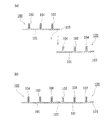
帯状部材100は、図1(a),(b)に示すように、可撓性を有するプラスチック、たとえば、ポリエチレン、ポリプロピレンなどを押出成形して形成され、中空円筒状に巻き重ねられて輸送用巻重体D(図7参照)に形成されて現場に輸送される。この帯状部材100は、帯板状の基板101の裏面に複数本(実施例においては3本)の断面I字状のリブ102が基板101と直交して立設されて形成されている。そして、基板101の一方の側縁部(以下、一側縁部という。)には、隣接する帯状部材100における基板101の他方の側縁部(以下、他側縁部という。)を配置することができるように、基板101の厚みだけ裏面側に段落ちした段落ち部103が形成されている。また、各リブ102には、鋼板などの補強ストリップ104が埋設されている。また、補強ストリップ104には、降伏強さ(0.2%耐力)が比較的高い材料が使用されている。また、補強ストリップ104は、補強ストリップ104の外面と、リブ102および基板101との間に空間が形成されないようにリブ102内および基板101内に埋設されている(リブ102および基板101に覆われている)。
As shown in FIGS. 1A and 1B, the belt-
ここで、本実施形態では、図1(b)に示すように、各リブ102と基板101の裏面との境界部分(接続部分)には、リブ102の外面から突出する方向に傾斜する傾斜面105が形成されている。傾斜面105は、リブ102の延びる方向に直交する方向の両端に形成されている。傾斜面105は、リブ102側から基板101側に向かってリブ102の幅が広くなるように形成されている。また、リブ102の延びる方向、および、基板101の延びる方向に対する傾斜面105の角度は、任意に設定可能である。
Here, in this embodiment, as shown in FIG. 1B, an inclined surface inclined in a direction protruding from the outer surface of the
また、補強ストリップ104の基板101側(表面側)の端部104aは、基板101の内部にまで延びている。具体的には、補強ストリップ104の端部104aは、基板101の一側縁部と他側縁部との間に配置されている。また、補強ストリップ104の断面形状は、帯状部材100の延びる方向(紙面手前から奥方向)から見て、長方形状である。また、補強ストリップ104の基板101から直立する方向の長さH1は、補強ストリップ104の基板101から直立する方向に直交する方向の長さH2の約15倍以上である。なお、図1(b)に示す補強ストリップ104の長さH1とH2との比率は、紙面のスペースの関係上、実際の比率とは異なる比率で示している。
Further, the
このような帯状部材100は、基板101の裏面側、すなわち、リブ102が立設された側が外周面側となるように(ガイドフレーム2の径方向外側を向いた状態で)、後述する製管機1に供給されて螺旋状に巻き回される。この際、図2(a),(b)に示すように、互いに隣接する帯状部材100,100のうち、後続する帯状部材100の一側縁部(段落ち部103)に溶融樹脂cを塗布するとともに、溶融樹脂cを塗布した後続する帯状部材100の一側縁部を、先行する帯状部材100の他側縁部に外側(先行する帯状部材100の外周面側)から重ね合わせことにより、後続する帯状部材100の基板101の一側縁部(段落ち部103)を先行する帯状部材100の基板101の他側縁部に配置して接合し、所定の管径の更生管S(図3参照)を製管するものである。
Such a belt-
次に、製管機1について、図3〜図6に基づいて説明する。
Next, the
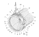
製管機1は、図3に示すように、帯状部材100を螺旋状に巻き回すガイドフレーム2および該ガイドフレーム2に周方向に間隔をおいて回転自在に設けられた複数個の案内ローラー3と、ガイドフレーム2に設けられ、螺旋状に巻き回されて先行する帯状部材100の他側縁部および後続して製管機1に供給される帯状部材100の一側縁部(段落ち部103)を重ね合わせるとともに、隣接する帯状部材100,100を挟み込んで送り出す駆動機構4と、駆動機構4の前段に位置してガイドフレーム2に設けられ、隣接する帯状部材100,100のうち、後続して製管機1に供給される帯状部材100の一側縁部103を軟化させるとともに、溶融樹脂cを吐出する押出溶接機5とから構成されている。
As shown in FIG. 3, the
ガイドフレーム2は、前後一対の環状フレーム21,21を周方向に間隔をおいて複数本の連結材22によって一体に連結して形成されている。そして、ガイドフレーム2は、複数個(実施例においては、120度ずつ3個)に分割されるようになっており、分割された状態で開口部としてのマンホール内に搬入され、マンホール内において、環状に組み立てられる。
The
なお、製管方向に対して後方側の環状フレーム21は、後述する駆動機構4および押出溶接機5に対応して円弧の一部が内方に向けてL字状に屈曲されている他、この屈曲部211に対応する部分には、円弧状の補助フレーム23が前後の環状フレーム21,21間に位置して製管方向前方の環状フレーム21に連結材22を介して連結されている。
In addition, the
案内ローラー3は、ガイドフレーム2を構成する前後の環状フレーム21,21間に固定された各連結軸31回りに軸受(図示せず)を介して回転自在に支持されている。
The
ただし、製管方向に対して前方側の環状フレーム21の屈曲部211に対応する部分の案内ローラー3は、補助フレーム23と後方の環状フレーム21との間において回転自在に支持されており、前後の環状フレーム21,21間に設けられた案内ローラー3の略半分の長さに形成されている。
However, the
ここで、案内ローラー3は、金属あるいは合成樹脂よりなり、帯状部材100の各リブ102を余裕を持って収容可能な幅と深さの複数個の溝3a(図4参照)が帯状部材100の各リブ102に対応して形成されている。これにより、案内ローラー3の外周面は、更生管Sを形成する帯状部材100における基板101の裏面に接触するようになっている。また、案内ローラー3によって裏面が規制されて螺旋状に巻き回される帯状部材100は、360度1周した際、先行する帯状部材100が後続する帯状部材100に対して帯状部材100の幅に略相当する長さだけ製管方向に向かってずれるように設定されている。すなわち、案内ローラー3は、周方向へ移動するにしたがって溝3aが管軸方向に徐々にずれるように、連結軸31に対する案内ローラー3の管軸方向の取付位置が調整されている。また、詳細には図示しないが、案内ローラー3の、帯状部材100の一側縁部(段落ち部103)に対応するローラー部は、その他のローラー部よりも若干小径に形成されている。
Here, the
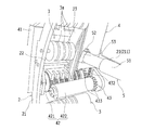
駆動機構4は、図3および図4に示すように、ガイドフレーム2における製管方向に対して後方側の環状フレーム21の屈曲部211および補助フレーム23間の空間を利用してガイドフレーム2に固定された取付フレーム41と、取付フレーム41に設けられた外面ローラー421および内面ローラー422が組になったピンチローラー42と、取付フレーム41に固定されて減速機構43を介してピンチローラー42を回転させる油圧モータ(図示せず)とから構成されている。
As shown in FIGS. 3 and 4, the
ここで、減速機構43は、取付フレーム41に設けた油圧モータの出力軸および外面ローラー421の回転軸にそれぞれ設けられたスプロケット431(外面ローラー421の回転軸に設けたスプロケットのみを図5に示す。)と、これらのスプロケット431間に巻回されたチェーン432と、外面ローラー421の回転軸および内面ローラー422の回転軸にそれぞれ設けられて互いに噛み合う歯車433,433からなり、油圧モータを回転駆動させることにより、スプロケット431、チェーン432を介して外面ローラー421を回転させるとともに、互いに噛み合う歯車433,433を介して内面ローラー422を外面ローラー421の回転方向とは逆方向に回転させるものである。
Here, the
また、外面ローラー421は、その外周面が帯状部材100の隣接するリブ102,102間において、その基板101の裏面、すなわち、更生管Sの外周面となる側の傾斜面105に接して回転する。この際、外面ローラー421の外周面にはローレット加工が施されており、帯状部材100を滑ることなく送り出すことができる。
Further, the
なお、外面ローラー421の、帯状部材100の一側縁部(段落ち部103)に対応する位置のローラーは、その他のローラーよりも若干小径に形成されるとともに、ローレット加工は施されていない。
In addition, the roller of the position corresponding to the one side edge part (step-fall part 103) of the strip | belt-shaped
一方、内面ローラー422は、たとえば、鉄やプラスチックなどの比較的硬い素材によって円筒状に形成され、その外周面が帯状部材100における基板101の平坦な表面、すなわち、更生管Sの内周面となる側の面に接触して回転する。
On the other hand, for example, the
押出溶接機5は、ボディ51に熱風機ユニット、可塑化ユニット、溶接棒供給ユニットから構成され、外気を取り入れて加熱し、吹出しノズル52を通して熱風を噴出させるとともに、ポリエチレンやポリプロピレンなどの線状プラスチックからなる溶接棒10(図3参照)を導いて加熱溶融させ、その溶融樹脂cを押出しノズル53から押し出すものである。そして、押出溶接機5は、吹出しノズル52および押出しノズル53が製管機1における駆動機構4のピンチローラー42に供給される直前の帯状部材100の一側縁部(段差部103)に略接触状態で対向するように、ガイドフレーム2における前方の環状フレーム21の屈曲部211と補助フレーム23間の空間を利用してガイドフレーム2に固定されている。
The
なお、溶接棒10は、帯状部材100を形成するプラスチック材料と同一材料を線状に形成したものであり、リール状に巻き重ねられて溶接棒リールRに形成されて押出溶接機5の近傍に位置してガイドフレーム2に設けられている。
The
ここで、押出溶接機5は、ガイドフレーム2の内方に位置して、かつ、吹出しノズル52および押出しノズル53を帯状部材100の一側縁部に略接触するように取り付けられており、帯状部材100の一側縁部を確実に熱風によって略溶融状態に軟化させるとともに、軟化させた一側縁部に溶融樹脂cを確実に塗布することができる。
Here, the
なお、隣接する帯状部材100,100の溶融樹脂cによる接合に際しては、後続する帯状部材100の一側縁部とともに、該後続する帯状部材100の一側縁部が重ね合わされる先行する帯状部材の他側縁部についても略溶融状態に軟化させることが好ましい。この場合は、新たな加熱空気の吹出しノズルを先行する帯状部材100の他側縁部に対向して配設すればよい。
When the adjacent belt-
次に、図3および図5〜図7を参照して、このように構成された製管機1を用いて既設管を更生する更生管Sの製管方法について開口部の一例としてマンホールを利用する場合を説明する。
Next, referring to FIG. 3 and FIGS. 5 to 7, a manhole is used as an example of an opening for a pipe making method of the renovated pipe S for rehabilitating an existing pipe using the
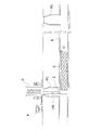
まず、既設管Kは所定スパン毎にマンホールが設けられており、隣接するマンホールにおいて、一方のマンホールM1を施工区間の発進マンホールに設定するとともに、他方のマンホールM2を到達マンホールに設定し、発進マンホールM1から到達マンホールM2に向けて既設管K内に更生管Sを製管する場合を説明する。 First, the existing pipe K is provided with a manhole for every predetermined span. In the adjacent manhole, one manhole M1 is set as a starting manhole in the construction section, and the other manhole M2 is set as a reaching manhole, and a starting manhole is set. The case where the renovated pipe S is manufactured in the existing pipe K from M1 toward the reaching manhole M2 will be described.
施工前の準備として、更生管Sの製管には、帯状部材100を巻き重ねた輸送用巻重体D、製管機1、動力ユニットPなどを用意し、輸送用巻重体D、動力ユニットPを発進マンホールM1側の地上に設置する。また、製管機1は、案内ローラー3を設けたガイドフレーム2、駆動機構4、押出溶接機5に分解されるとともに、ガイドフレーム2はさらに複数個に分割される。そして、分割された製管機1の各要素は、マンホールM1を通して内部に搬入された後、組み立てられる。組み立てられた製管機1は、発進マンホールM1において、トラッククレーンなどを利用して吊下げ状態に支持される(図3参照)。
As preparation before construction, for the production of the rehabilitated pipe S, a transport roll D, a
このような準備作業が完了すれば、地上に配置した輸送用巻重体Dから帯状部材100を引き出して発進マンホールM1内に引き込み、発進マンホールM1内に支持されている製管機1における駆動機構4の取付フレーム41を経てピンチローラー42に供給するとともに、ピンチローラー42から引き出してガイドフレーム2に設けた案内ローラー3の内周側に送り出す。また、ピンチローラー42(外面ローラー421および内面ローラー422)は、図3および図7に示すように、輸送用巻重体Dから製管機1に供給された帯状部材100を所定の曲率半径で変形させる機能を有している。ピンチローラー42から引き出されて案内ローラー3の内周側に送り出された帯状部材100は、そのリブ102が案内ローラー3の溝3aに案内されて螺旋状に巻き回される。
When such a preparatory work is completed, the belt-
ここで、本実施形態では、図5および図6に示すように、帯状部材100がピンチローラー42に供給された際には、帯状部材100の傾斜面105は、ピンチローラー42の外面ローラー421の角部421aと接触(当接)する。これにより、リブ102の両側に形成された傾斜面105が補強ストリップ104側に圧縮(押圧)されるので、補強ストリップ104の端部104a近傍が拘束されるようになり、帯状部材100が巻き回される際に補強ストリップ104の端部104aが座屈(波打ち)しにくくなる。
Here, in this embodiment, as shown in FIG. 5 and FIG. 6, when the belt-shaped
そして、帯状部材100は、ガイドフレーム2の案内ローラー3に沿って360度螺旋状に巻き回される。この際、帯状部材100の傾斜面105は、案内ローラー3とは接触していない。また、案内ローラー3は、ピンチローラー42とは異なり、帯状部材100を所定の曲率半径で変形させる機能を有していない。その後、帯状部材100が再び駆動機構4のピンチローラー42に達した際には、その幅の分だけ製管方向にずれてピンチローラー42の前方に位置しており、その他側縁部に、連続的に供給される後続する帯状部材100の一側縁部が重なり合うようになっている。
The belt-
ここで、押出溶接機5を作動させると、外気を吸引して加熱するとともに、その加熱空気を吹出しノズル52から後続する帯状部材100の一側縁部に向けて噴出させて略溶融状態に軟化させるとともに、溶接棒リールRから溶接棒10を内部に引き込んで加熱溶融させ、溶融樹脂cを押出しノズル53から押し出して後続する帯状部材100の一側縁部(段落ち部103)に塗布する。この場合、押出溶接機5は、ガイドフレーム2の内方において取り付けられるとともに、その押出ノズル53が後続する帯状部材100の一側縁部に略接触状態で対向していることにより、溶融樹脂cを帯状部材100の一側縁部に確実に塗布することができる。
Here, when the
この状態で、図5に示すように、駆動機構4の油圧モータを回転駆動すれば、スプロケット431、チェーン432を介して外面ローラー421を回転させるとともに、互いに噛み合う歯車433,433を介して内面ローラー422を外面ローラー421の回転方向とは逆方向に回転させ、先行する帯状部材100および後続する帯状部材100を挟み込み、先行する帯状部材100の他側縁部に後続する帯状部材100の一側縁部(段落ち部103)を重ね合わせて周方向に向けて送り出す。この際、後続する帯状部材100の一側縁部が略溶融状態に軟化されているとともに、その一側縁部に溶融樹脂cが塗布されていることにより、ピンチローラー42に挟み込まれた隣接する帯状部材100,100は、先行する帯状部材100の他側縁部に後続する帯状部材100の一側縁部が一体に接合されて周方向に向けて送り出される。すなわち、案内ローラー3に沿って螺旋状に巻き回された隣接する帯状部材100,100は、ピンチローラー42から送り出される際に、それらの他側縁部および一側縁部が螺旋状に巻き回された状態で一体に接合されて管体に製管され、更生管Sとして回転しつつ前方に向けて送り出される。
In this state, as shown in FIG. 5, if the hydraulic motor of the
以下、帯状部材100は、一側縁部が略溶融状態に軟化されるとともに、その一側縁部に溶融樹脂cが塗布されて連続的に駆動機構4のピンチローラー42に供給されることにより、ピンチローラー42において、先行する帯状部材100の他側縁部に後続する帯状部材100の一側縁部を一体に接合して周方向に押し出し、更生管Sを連続的に製管するものである。そして、製管された更生管Sは、回転しつつ押し出されることにより、製管機1より離脱し、到達マンホールM2に向けて既設管Kに挿入される(図7参照)。
Hereinafter, the belt-
このようにして、製管機1に連続的に供給される帯状部材100から更生管Sを製管し、製管された更生管Sを既設管K内に回転しつつ挿入し、更生管Sの先端が到達マンホールM2に到達して既設管Kの施工対象区間の全長にわたって更生管Sの製管が終了すれば、更生管Sの管端部の帯状部材100を切断した後、製管機1を分解し、発進マンホールM1から撤去する。すなわち、ガイドフレーム2から駆動機構4および押出溶接機5を取り外すとともに、ガイドフレーム2を複数個に分割し、発進マンホールM1から引き上げる。
In this way, the rehabilitated pipe S is produced from the belt-
その後、詳細には図示しないが、既設管Kと更生管Sの両端部との隙間にシール部材を配設して隙間に水などが浸入しないように密封するとともに、シール部材を通して裏込め材を隙間に充填する。裏込め材が固化すれば、固化した裏込め材によって更生管Sが既設管Kに固定される。次いで、更生管Sの、マンホールM1,M2内への突出部分を切除して作業完了となる。 After that, although not shown in detail, a seal member is disposed in the gap between the existing pipe K and the both ends of the renovated pipe S so that water or the like does not enter the gap, and the backfill material is passed through the seal member. Fill the gap. When the backfill material is solidified, the rehabilitated pipe S is fixed to the existing pipe K by the solidified backfill material. Next, the protruding portion of the rehabilitation pipe S into the manholes M1 and M2 is cut off to complete the operation.
以上説明したように、本実施形態による帯状部材100およびこれを用いた製管方法によれば、以下に列記するような効果が得られる。
As described above, according to the belt-
本実施形態では、上記のように、製管機1の環状のガイドフレーム2の周方向に回転自在に支持された複数のローラー(ピンチローラー42、案内ローラー3)により帯状部材100のリブ102がガイドフレーム2の径方向外側を向いた状態で製管機1に供給される際に、帯状部材100を所定の曲率半径で変形させる外面ローラー421と帯状部材100の傾斜面105とを接触(当接)させることによって、製管時に帯状部材100を所定の曲率半径で変形させる外面ローラー421と傾斜面105とが接触した際に、傾斜面105が補強ストリップ104側へ押圧されることとなる。これにより、補強ストリップ104の動き(移動)が拘束されるので、製管時に補強ストリップ104の端部104aが座屈するのを抑制することができる。また、補強ストリップ104の端部104aを、基板101の内部にまで延ばして配置することによって、補強ストリップ104の端部104aが基板101により拘束(固定)されるので、製管時における補強ストリップ104の端部104aの座屈を抑制することができる。また、リブ102と補強ストリップ104との間に隙間が形成されていないことによって、製管時に帯状部材100が所定の曲率半径で変形した際に、リブ102内に補強ストリップ104が移動する空間がないので、補強ストリップ104が座屈(波打ち)するのを抑制することができる。これらにより、補強ストリップ104の端部104aが座屈するのを抑制することができるので、降伏強さの高い補強ストリップ104が使用可能となり、土被りが大きいまたは大口径での施工を行うことができる。
In the present embodiment, as described above, the
また、本実施形態では、上記のように、製管機1の環状のガイドフレーム2の周方向に回転自在に支持された複数のローラー(ピンチローラー42、案内ローラー3)により帯状部材100のリブ102がガイドフレーム2の径方向外側を向いた状態で製管機1に供給される際に、複数の案内ローラー3と帯状部材100の傾斜面105とを接触させないことによって、製管時に案内ローラー3により帯状部材100の傾斜面105が押圧されないので、帯状部材100に余分な力が加わらないようにすることができる。
In the present embodiment, as described above, the ribs of the belt-shaped
また、本実施形態では、上記のように、補強ストリップ104の基板101から直立する方向の長さH1を、補強ストリップ104の基板101から直立する方向に直交する方向の長さH2の15倍以上とするのが好ましい。
In the present embodiment, as described above, the length H1 of the reinforcing
−他の実施形態−
なお、今回開示された実施形態は、すべての点で例示であって制限的なものではないと考えられるべきである。本発明の範囲は、上記した実施形態の説明ではなく特許請求の範囲によって示され、さらに特許請求の範囲と均等の意味および範囲内でのすべての変更が含まれる。
-Other embodiments-
The embodiment disclosed this time should be considered as illustrative in all points and not restrictive. The scope of the present invention is shown not by the above description of the embodiments but by the scope of claims for patent, and further includes all modifications within the meaning and scope equivalent to the scope of claims for patent.
たとえば、上記実施形態では、帯状部材100に3つのリブ102を設ける例を示したが、本発明はこれに限られない。本発明では、帯状部材100に1つ、2つ、または、4つ以上のリブ102を設けてもよい。
For example, in the above-described embodiment, an example in which the three
また、上記実施形態では、補強ストリップ104の基板101から直立する方向の長さH1を、補強ストリップ104の基板101から直立する方向に直交する方向の長さH2の15倍以上とする例を示したが、本発明はこれに限られない。上記実施形態において、補強ストリップ104の長さH1を長さH2の15倍以上とするのは好適な例であるので、長さH1と長さH2との比率は適宜設定してもよい。
Moreover, in the said embodiment, the example which makes length H1 of the direction which stands upright from the board |
本発明は、更生管製管用補強材入り帯状体およびこれを用いた製管方法に利用可能であり、さらに詳しくは、老朽化した下水管路、上水管路、農業用水路、および、ガス管路などの既設管を更生する更生管を製管する際に用いられる更生管製管用補強材入り帯状体およびこれを用いた製管方法に利用することができる。 INDUSTRIAL APPLICABILITY The present invention can be used for a strip containing a reinforcing material for pipe making of rehabilitated pipe and a pipe making method using the same, and more specifically, an aging sewer pipe, a water pipe, an agricultural water pipe, and a gas pipe. It can utilize for the strip | belt-shaped body with the reinforcing material for rehabilitation pipe | tube pipes used when manufacturing the rehabilitation pipe | tube which rehabilitates existing pipe | tubes, etc., and the pipe making method using the same.
1 製管機
2 ガイドフレーム
3 案内ローラー
4 駆動機構
5 押出溶接機
42 ピンチローラー
100 帯状部材(更生管製管用補強材入り帯状体)
101 基板
102 リブ
104 補強ストリップ(補強材)
104a 端部
105 傾斜面
421 外面ローラー
421a 角部
422 内面ローラー
S 更生管
K 既設管
M1、M2 マンホール
DESCRIPTION OF
101
104a
Claims (4)
前記基板と前記リブとの境界部分には、前記リブの外面から突出する方向に傾斜する傾斜面が形成され、
前記補強材の前記基板側の端部は、前記基板の内部にまで延びていることを特徴とする更生管製管用補強材入り帯状体。 It is a strip-shaped body with a reinforcing material for pipe making of rehabilitation pipe that is wound spirally to form a rehabilitation pipe, and a gap is not formed over the entire length of the rib plate-like substrate, a rib standing upright from the substrate In a strip with a reinforcing material for rehabilitating pipes, comprising a reinforcing material made of a metal plate embedded in
An inclined surface that is inclined in a direction protruding from the outer surface of the rib is formed at a boundary portion between the substrate and the rib,
An end portion of the reinforcing member on the substrate side extends to the inside of the substrate.
前記補強材の断面形状は、前記更生管製管用補強材入り帯状体の延びる方向から見て、長方形状であり、
前記補強材の前記基板から直立する方向の長さは、前記補強材の前記基板から直立する方向に直交する方向の長さの15倍以上であることを特徴とする更生管製管用補強材入り帯状体。 In the strip | belt shaped body with the reinforcement material for pipe renovation pipes of Claim 1,
The cross-sectional shape of the reinforcing material is a rectangular shape when viewed from the direction in which the strip-shaped body with the reinforcing material for pipes made of rehabilitation pipes extends,
The length of the reinforcing material in the direction erecting from the substrate is 15 times or more of the length of the reinforcing material in the direction perpendicular to the direction erecting from the substrate. Banded body.
前記製管方法に用いられる更生管製管用補強材入り帯状体の前記基板と前記リブとの境界部分には、前記リブの外面から突出する方向に傾斜する傾斜面が形成されており、
前記製管機の環状のガイドフレームの周方向に回転自在に支持された複数のローラーにより、前記更生管製管用補強材入り帯状体のリブが前記ガイドフレームの径方向外側を向いた状態で前記製管機に供給される際に、前記複数のローラーのうち前記更生管製管用補強材入り帯状体を所定の曲率半径で変形させるローラーと前記傾斜面とを接触させることを特徴とする更生管製管用補強材入り帯状体を用いた製管方法。 Using a strip-shaped body with a reinforcing material for pipes made of rehabilitation pipe, comprising a strip-shaped substrate, a rib standing upright from the substrate, and a reinforcing material made of a metal plate embedded so that no gap is formed over the entire length of the rib It is a pipe making method, spirally winding the rehabilitated pipe-made reinforcing member-like strip supplied to a pipe making machine, and spirally adjacent one side of the rehabilitating-pipe-made reinforcing member containing the reinforcing member In the pipe making method of inserting the rehabilitated pipe into the existing pipe while making the rehabilitated pipe by sequentially joining the edge part and the other side edge part,
An inclined surface that is inclined in a direction protruding from the outer surface of the rib is formed at a boundary portion between the substrate and the rib of the band-shaped body for reinforcing pipe-making pipe used in the pipe making method,
With the plurality of rollers rotatably supported in the circumferential direction of the annular guide frame of the pipe making machine, the ribs of the band-shaped body with the reinforcing material for pipe making of rehabilitation pipe face the radially outer side of the guide frame. A rehabilitating pipe characterized in that, when being supplied to a pipe making machine, a roller that deforms the band-like body with the reinforcing material for rehabilitating pipe making at a predetermined radius of curvature and the inclined surface among the plurality of rollers are brought into contact with each other. A pipe making method using a band-like body with a reinforcing material for pipe making.
前記製管機の環状のガイドフレームの周方向に回転自在に支持された複数のローラーにより、前記更生管製管用補強材入り帯状体のリブが前記ガイドフレームの径方向外側を向いた状態で前記製管機に供給される際に、前記複数のローラーのうち前記更生管製管用補強材入り帯状体を所定の曲率半径で変形させるローラー以外のローラーと前記傾斜面とを接触させないことを特徴とする更生管製管用補強材入り帯状体を用いた製管方法。 In the pipe making method using the strip | belt body containing the reinforcing material for pipe renovation pipes of Claim 3,
With the plurality of rollers rotatably supported in the circumferential direction of the annular guide frame of the pipe making machine, the ribs of the band-shaped body with the reinforcing material for pipe making of rehabilitation pipe face the radially outer side of the guide frame. When being supplied to a pipe making machine, the inclined surface is not brought into contact with a roller other than a roller that deforms the band-like body with the reinforcing material for pipe rehabilitation pipe making at a predetermined curvature radius among the plurality of rollers. A pipe making method using a band with reinforcing material for pipe making.
Priority Applications (1)
| Application Number | Priority Date | Filing Date | Title |
|---|---|---|---|
| JP2014121294A JP2016000490A (en) | 2014-06-12 | 2014-06-12 | Belt-like body including reinforcement material for pipe production of corrected pipe and pipe production method using the same |
Applications Claiming Priority (1)
| Application Number | Priority Date | Filing Date | Title |
|---|---|---|---|
| JP2014121294A JP2016000490A (en) | 2014-06-12 | 2014-06-12 | Belt-like body including reinforcement material for pipe production of corrected pipe and pipe production method using the same |
Publications (1)
| Publication Number | Publication Date |
|---|---|
| JP2016000490A true JP2016000490A (en) | 2016-01-07 |
Family
ID=55076352
Family Applications (1)
| Application Number | Title | Priority Date | Filing Date |
|---|---|---|---|
| JP2014121294A Pending JP2016000490A (en) | 2014-06-12 | 2014-06-12 | Belt-like body including reinforcement material for pipe production of corrected pipe and pipe production method using the same |
Country Status (1)
| Country | Link |
|---|---|
| JP (1) | JP2016000490A (en) |
Cited By (1)
| Publication number | Priority date | Publication date | Assignee | Title |
|---|---|---|---|---|
| WO2018168988A1 (en) * | 2017-03-16 | 2018-09-20 | テルモ株式会社 | Medicinal liquid administering device |
-
2014
- 2014-06-12 JP JP2014121294A patent/JP2016000490A/en active Pending
Cited By (1)
| Publication number | Priority date | Publication date | Assignee | Title |
|---|---|---|---|---|
| WO2018168988A1 (en) * | 2017-03-16 | 2018-09-20 | テルモ株式会社 | Medicinal liquid administering device |
Similar Documents
| Publication | Publication Date | Title |
|---|---|---|
| JP5155756B2 (en) | Apparatus for forming curl of strip-shaped member with reinforcing material, method for producing spiral tube, method for producing the same, and method for rehabilitating existing tube | |
| US20100008731A1 (en) | Pipe producing apparatus and existing pipe rehabilitating method employing the same | |
| US20130247632A1 (en) | Method for producing spiral pipe | |
| JP5291399B2 (en) | Rehabilitation of existing pipes | |
| JP2012250414A (en) | Method of manufacturing member for pipe manufacturing | |
| JP2009023296A (en) | Manufacturing method of reinforcing member of band-like article, long band-like article and regeneration method of existing pipe | |
| JP5268773B2 (en) | Rehabilitation pipe manufacturing method | |
| JP4674082B2 (en) | Lining method for existing pipe and pipe making machine | |
| JP2016000490A (en) | Belt-like body including reinforcement material for pipe production of corrected pipe and pipe production method using the same | |
| JP2010023350A (en) | Tube forming apparatus and method for forming tubular body using the tube forming apparatus | |
| JP5992726B2 (en) | Rehabilitated pipe manufacturing method, rehabilitated pipe manufacturing apparatus and strip | |
| JP6200307B2 (en) | Pipe making equipment | |
| JP5596436B2 (en) | Apparatus for correcting curl wrinkle of band member with reinforcing material and method for producing rehabilitation pipe | |
| JP2009144744A (en) | Positioning mechanism of regulating frame in spiral winding pipe forming device having regulating frame and lining construction method using the device | |
| JP2019084728A (en) | Pipe manufacturing equipment for spiral tube | |
| JP6220654B2 (en) | Rehabilitation of existing pipes | |
| JP7044605B2 (en) | Rehabilitation tube unwinding method and unwinding band material | |
| JP5166896B2 (en) | Pipe making apparatus and pipe making method | |
| JP2009023295A (en) | Long band-like article used for regeneration method of existing pipe and regeneration method of existing pipe | |
| JP5641606B2 (en) | Rehabilitation pipe manufacturing method | |
| JP6196540B2 (en) | Strip-shaped member molding apparatus and molding method therefor | |
| JP5507972B2 (en) | Rehabilitation pipe making machine | |
| JP5358156B2 (en) | Rehabilitated pipe production apparatus and rehabilitated pipe production method | |
| JP2014054741A (en) | Device for making regeneration pipe | |
| JP2013230601A (en) | Method for making regeneration pipe |