JP2015528362A - Epilation device with open configuration - Google Patents
Epilation device with open configuration Download PDFInfo
- Publication number
- JP2015528362A JP2015528362A JP2015531663A JP2015531663A JP2015528362A JP 2015528362 A JP2015528362 A JP 2015528362A JP 2015531663 A JP2015531663 A JP 2015531663A JP 2015531663 A JP2015531663 A JP 2015531663A JP 2015528362 A JP2015528362 A JP 2015528362A
- Authority
- JP
- Japan
- Prior art keywords
- tweezers
- housing
- shoulder
- hair
- opening
- Prior art date
- Legal status (The legal status is an assumption and is not a legal conclusion. Google has not performed a legal analysis and makes no representation as to the accuracy of the status listed.)
- Pending
Links
Images
Classifications
-
- A—HUMAN NECESSITIES
- A45—HAND OR TRAVELLING ARTICLES
- A45D—HAIRDRESSING OR SHAVING EQUIPMENT; EQUIPMENT FOR COSMETICS OR COSMETIC TREATMENTS, e.g. FOR MANICURING OR PEDICURING
- A45D26/00—Hair-singeing apparatus; Apparatus for removing superfluous hair, e.g. tweezers
- A45D26/0023—Hair-singeing apparatus; Apparatus for removing superfluous hair, e.g. tweezers with rotating clamping elements
- A45D26/0028—Hair-singeing apparatus; Apparatus for removing superfluous hair, e.g. tweezers with rotating clamping elements with rotating discs or blades
-
- A—HUMAN NECESSITIES
- A45—HAND OR TRAVELLING ARTICLES
- A45D—HAIRDRESSING OR SHAVING EQUIPMENT; EQUIPMENT FOR COSMETICS OR COSMETIC TREATMENTS, e.g. FOR MANICURING OR PEDICURING
- A45D26/00—Hair-singeing apparatus; Apparatus for removing superfluous hair, e.g. tweezers
-
- A—HUMAN NECESSITIES
- A45—HAND OR TRAVELLING ARTICLES
- A45D—HAIRDRESSING OR SHAVING EQUIPMENT; EQUIPMENT FOR COSMETICS OR COSMETIC TREATMENTS, e.g. FOR MANICURING OR PEDICURING
- A45D26/00—Hair-singeing apparatus; Apparatus for removing superfluous hair, e.g. tweezers
- A45D2026/008—Details of apparatus for removing superfluous hair
- A45D2026/009—Details of apparatus for removing superfluous hair with additional lotion applicator, e.g. interchangeable
Landscapes
- Surgical Instruments (AREA)
- Massaging Devices (AREA)
- Finger-Pressure Massage (AREA)
Abstract
脱毛装置1は、ハンドル4と、開いた顎部10を形成する第1及び第2の肩部6、8と、を定義する筐体2を持つ。軸のまわりに回転するよう顎部10に毛抜き部12が装着され、筐体2の前側22から筐体2の後側24まで装置1を通して開口20が形成され、開口20は、ハンドル4、肩部6、8及び毛抜き部12によって境界付けられる。筐体2内に配置された駆動機構36が、該軸のまわりに毛抜き部12を回転させるような回転運動をもたらすよう構成される。前側22から後側24まで脱毛器1の筐体2を通る開口20を備えることにより、毛抜き部12の下に毛及び屑が集まることが回避される。The epilation device 1 has a housing 2 that defines a handle 4 and first and second shoulders 6, 8 that form an open jaw 10. A tweezer 12 is mounted on the jaw 10 to rotate about an axis, and an opening 20 is formed through the device 1 from the front side 22 of the housing 2 to the rear side 24 of the housing 2. It is bounded by the parts 6, 8 and the tweezers 12. A drive mechanism 36 disposed within the housing 2 is configured to provide a rotational movement that rotates the tweezers 12 about the axis. By providing the opening 20 that passes through the housing 2 of the epilator 1 from the front side 22 to the rear side 24, it is avoided that hair and debris collect under the tweezers 12.
Description
本発明は、脱毛装置に関し、特に毛抜き部の改善された洗浄を可能とする改善された構成に関する。 The present invention relates to a hair removal device, and more particularly to an improved configuration that allows improved cleaning of the tweezers.
ユーザの身体の種々の領域から望ましくない毛を除去する目的のための、種々のタイプの脱毛装置が知られている。動作の原理は大きく異なるが、これらの装置のなかでは、かなりの群が、毛を捉えて皮膚/毛包から能動的に抜き取る、回転する毛抜き機構を使用して動作する。該毛抜き器が更に回転すると、該毛を離す。本文脈において、「毛抜き器(tweezers)」は、毛を把持して抜き取るために開閉が可能な構成を示すために用いられる。 Various types of epilation devices are known for the purpose of removing unwanted hair from various areas of a user's body. Although the principles of operation vary widely, in these devices, a significant group operates using a rotating tweezer mechanism that captures hair and actively extracts it from the skin / follicle. As the tweezer rotates further, the hair is released. In this context, “tweezers” are used to indicate a configuration that can be opened and closed to grip and remove hair.
このタイプの最も初期の装置の1つは、コイルばねの回転を利用して毛を捉えて離す、Epilady(登録商標)装置である。毛抜き装置が、使用の間にユーザの皮膚の輪郭に追従するよう変形することができる柔軟な又は弾力性のある軸を有するような、幾つかの同様の装置が存在する。 One of the earliest devices of this type is the Epilady® device that uses the rotation of a coil spring to capture and release the hair. There are several similar devices such that the tweezers have a flexible or elastic shaft that can be deformed to follow the contours of the user's skin during use.
比較的堅固な軸又はシャフトに装着された毛抜き機構を使用する、他の装置が開発されている。該シャフトは、直線状であっても湾曲していても良い。斯かる装置は有利にも、例えば窪んだ身体部分のような困難な位置に到達するよう試みる場合に、形状を維持する。装置の1つは欧州特許出願公開EP532106B1に開示されており、本文献の内容全体は参照により本明細に組み込まれたものとする。当該装置は、圧縮部材の影響の下、互いに向かって枢動可能な回転ディスクを用いる。これら回転ディスクは、ディスクパッケージを形成し、該ディスクパッケージのいずれかの端における歯車支持部材により担持される歯車間で回転する軸により担持される。該圧縮部材は、歯車支持部材内に配置されたローラ部材を有する。該ディスクパッケージを回転させる駆動機構もまた歯車支持部材の領域に配置され、該領域は該装置の肩部と呼ばれ得る。 Other devices have been developed that use a tweezer mechanism mounted on a relatively rigid shaft or shaft. The shaft may be linear or curved. Such a device advantageously maintains its shape when attempting to reach difficult positions, such as a recessed body part. One apparatus is disclosed in European Patent Application Publication No. EP532106B1, the entire contents of which are incorporated herein by reference. The device uses rotating disks that are pivotable towards each other under the influence of a compression member. These rotating disks form a disk package and are carried by a shaft that rotates between gears carried by a gear support member at either end of the disk package. The compression member has a roller member disposed within the gear support member. A drive mechanism for rotating the disk package is also disposed in the region of the gear support member, which region may be referred to as the shoulder of the device.
脱毛の間、抜かれた毛は排出される必要がある。脱毛器の既存の設計は、毛抜き機構を少なくとも部分的に囲む筐体を持つ。毛は毛抜き器と筐体との間の空間に集まる傾向があり、取り除くのが困難となるか又は見苦しいものとなり得る。敏感な領域において使用される脱毛器については、毛抜き機構の能動部分のまわりに付加的な保護部が配置され得る。斯かる保護部は更に、抜き取られた毛の保持を増大させる。 During hair removal, the extracted hair needs to be discharged. Existing designs of epilators have a housing that at least partially surrounds the tweezer mechanism. The hair tends to collect in the space between the tweezer and the housing and can be difficult or unsightly to remove. For epilators used in sensitive areas, an additional guard can be placed around the active part of the tweezer mechanism. Such a protective part further increases the retention of the extracted hair.
脱毛装置の設計及び使用の間に遭遇され得る更なる問題は、皮膚を挟んでしまうことである。とりわけ、柔らかく支持されていない皮膚の領域については、回転する毛抜き器が、該毛抜き器と筐体との間の空間へと皮膚のひだを引き入れてしまい得る。また、毛抜き器自体が、最も開いた位置から閉じ始めるときに、皮膚を噛んでしまい得る。 A further problem that may be encountered during the design and use of a hair removal device is pinching the skin. In particular, for areas of skin that are not softly supported, a rotating tweezer can draw skin folds into the space between the tweezer and the housing. Also, the tweezer itself can bite the skin when it begins to close from its most open position.
以上に鑑みると、綺麗な外観及び容易な洗浄を確実にしつつ、身体の困難な領域への優れたアクセスを可能とする、脱毛装置を提供することが望ましい。 In view of the above, it is desirable to provide a hair removal device that allows excellent access to difficult areas of the body while ensuring a clean appearance and easy cleaning.
本発明によれば、毛を挟み、引き抜き、離すことによって、皮膚から毛を取り除くための脱毛装置が提供される。該脱毛装置は、ハンドルと、該ハンドルから延在する第1の肩部及び第2の肩部であって該第1の肩部と前記第2の肩部との間に開いた顎部を形成する第1の肩部及び第2の肩部と、を定義する、筐体を有する。軸、第1及び第2の端部、並びに少なくとも一対の毛抜き要素を持つ毛抜き部が装着され、該毛抜き部は、使用の間に該軸のまわりに回転し、毛が挟まれ得る少なくとも1つの挟み部を該毛抜き部の周縁に定義する。該毛抜き部は、前記第1及び第2の端部が、それぞれ第1及び第2の肩部によって支持され、且つ前記ハンドルからの距離が、前記筐体の前側から前記筐体の後側まで前記装置を通して開口が形成されるようなものとなるように、前記顎部に装着され、ここで前記開口は前記ハンドル、前記肩部及び前記毛抜き部によって境界付けられる。前記筐体内に配置される駆動機構が、回転運動をもたらし、前記軸のまわりに前記毛抜き部を回転させる。前側から後側まで脱毛器の筐体を通して開口を提供することにより、毛抜き部の下に毛及び屑が集まることが回避される。重要なことに、該開口の存在により、該毛抜き部が回転するときに、該毛抜き部と筐体との間に皮膚が捉われなくなる。 According to the present invention, a hair removal device is provided for removing hair from the skin by pinching, pulling and releasing the hair. The epilation device includes a handle and a first shoulder and a second shoulder extending from the handle, the jaw being open between the first shoulder and the second shoulder. A housing defining a first shoulder and a second shoulder to be formed; A tweezers having a shaft, first and second ends, and at least one pair of tweezer elements is mounted, the tweezers rotating around the shaft during use and at least one hair can be pinched A sandwiching portion is defined at the periphery of the tweezers. The tweezers are supported by the first and second shoulders at the first and second ends, respectively, and the distance from the handle is from the front side of the casing to the rear side of the casing. The jaws are mounted such that an opening is formed through the device, where the opening is bounded by the handle, the shoulder and the tweezers. A drive mechanism disposed within the housing provides a rotational movement to rotate the tweezers about the axis. By providing an opening through the epilator housing from the front side to the back side, it is avoided that hair and debris collect under the tweezers. Importantly, the presence of the opening prevents the skin from being trapped between the tweezer and the housing when the tweezer rotates.
好適には「開口」とは、自由な経路又は視線の開口である。「開口」とは少なくとも、開位置において一対の毛抜き要素を通して可視となるような単なる亀裂以上のものであると理解されるべきである。しかしながら、十分な自由な経路を持つ湾曲又は屈曲した開口であっても、皮膚を挟むことを回避しつつ、毛抜き部の下から毛及び屑が出ることを可能とする効果を達成し得ることは、理解されるであろう。 Preferably, the “opening” is a free path or line of sight opening. An “opening” should be understood to be more than just a crack that is visible through a pair of tweezer elements in an open position. However, even a curved or bent opening with a sufficiently free path can achieve the effect of allowing hair and debris to come out under the tweezers while avoiding pinching the skin. Will be understood.
好適には、該開口は、1cm2よりも大きい断面を持つ。該開口の実際のサイズは、該装置の全体のサイズに依存するが、一般的に1cm2を超えるものとなる。好適には、該開口は、最も小さい寸法において、高さが少なくとも5mmである。この寸法は、皮膚を摘まむことが問題となり得る下限であると考えられる。しかしながら、一般的には、該開口は、筐体の前側において高さが少なくとも10mmであっても良い。最も好適には、該開口は、毛抜き部の略幅全体に亘って、又は少なくとも挟み領域の幅に亘って延在する。本発明の文脈において「幅」とは、毛抜き部の軸に概ね平行な方向を示すことを意図されている。「高さ」とは、毛抜き部に対して径方向を示すことを意図されている。筐体の前側及び後側とは、使用時の該装置又は筐体のいずれの実際の向きによっても限定されるものではなく、毛抜き要素の対が挟み領域において後側から前側へ向けて、即ち筐体の前側における開口に向けて動くようなものである、毛抜き部の回転の方向に対応することを意図されている。 Preferably, the opening has a larger cross-section than 1 cm 2. The actual size of the opening depends on the overall size of the device, but will generally exceed 1 cm 2 . Preferably, the opening is at least 5 mm in height in the smallest dimension. This dimension is considered to be the lower limit where pinching the skin can be problematic. However, in general, the opening may be at least 10 mm high on the front side of the housing. Most preferably, the opening extends over substantially the entire width of the tweezers, or at least over the width of the pinching region. “Width” in the context of the present invention is intended to indicate a direction generally parallel to the axis of the tweezers. “Height” is intended to indicate the radial direction with respect to the tweezers. The front side and the rear side of the housing are not limited by the actual orientation of the device or the housing at the time of use, and the pair of tweezer elements are directed from the rear side to the front side in the pinching region, that is, It is intended to correspond to the direction of rotation of the tweezers, such as moving towards the opening on the front side of the housing.
また、該開口は好適には、筐体の最大幅の少なくとも半分の幅を持つ。従って、前記肩部間の開いた空間が、該肩部自体の幅に比べて比較的広いことは、理解されるであろう。 The opening preferably has a width at least half the maximum width of the housing. Accordingly, it will be understood that the open space between the shoulders is relatively wide compared to the width of the shoulder itself.
上述したように、該開口の好適なサイズは、該装置のサイズに少なくとも部分的に依存する。特に、該開口は好適には、毛抜き部の半径に少なくとも等しく、該毛抜き部の直径に対応してさえも良い、高さを持っていても良い。該毛抜き部は好適には、12mm乃至20mmの直径を持ち、最も好適には約15mmの直径を持つ。 As mentioned above, the preferred size of the opening depends at least in part on the size of the device. In particular, the opening may preferably have a height that is at least equal to the radius of the tweezers and may even correspond to the diameter of the tweezers. The tweezers preferably have a diameter of 12 mm to 20 mm, most preferably about 15 mm.
本装置は、到達が困難な位置及び敏感な位置における脱毛において、特に有用であると考えられる。斯かる目的のため、該毛抜き部は好適には、2よりも小さな幅対直径比を持ち、このことは比較的低い円筒の形を持つことを意味する。該毛抜き部は、直径よりも小さな幅を持ってさえも良い。 The device is considered particularly useful for hair removal in difficult to reach and sensitive locations. For this purpose, the tweezers preferably have a width-to-diameter ratio of less than 2, which means that they have a relatively low cylindrical shape. The tweezers may even have a width smaller than the diameter.
該開口は、目的を達成するため、いずれの適切な形状を持っても良い。好適な一実施例においては、開いた顎部が全体的にU字型であり、肩部が顎方向におけるハンドル部から延在する。該開口はD字型であり、該D字の直線側が毛抜き部によって形成される。従って結果として、該開口の下側面は比較的平滑であり、屑が集まり得る鋭い角がない。該下側面はまた、筐体の内側に向けて閉じられ、ハンドル並びに第1及び第2の肩部が、本質的に閉じた筐体を形成し、毛及びその他の屑の進入を防ぐ。該筐体は、防水であっても良い。 The opening may have any suitable shape to achieve the purpose. In a preferred embodiment, the open jaw is generally U-shaped and the shoulder extends from the handle in the jaw direction. The opening is D-shaped, and the straight side of the D-shape is formed by the tweezers. Consequently, as a result, the lower side of the opening is relatively smooth and has no sharp corners where debris can collect. The lower surface is also closed toward the inside of the housing, and the handle and the first and second shoulders form an essentially closed housing to prevent the entry of hair and other debris. The housing may be waterproof.
本発明は、種々の形態の毛抜き部によって動作する、種々のタイプの脱毛装置に適用可能である。該装置の最も好適な実施例においては、該毛抜き部は、外周に毛抜き要素を持つ複数のディスクを有し、これらディスクは、軸における回転のために装着され、該毛抜き要素が挟み領域において互いに係合するように付勢される。このことは、毛抜き要素が例えばカムにより動作させられる棒によって動作させられるカムベースのシステムにも同等に適用可能であることは、理解されるであろう。 The present invention is applicable to various types of epilation devices that operate with various forms of tweezers. In the most preferred embodiment of the device, the tweezers comprise a plurality of discs with tweezer elements on the outer periphery, the discs being mounted for rotation in the shaft, wherein the tweezer elements are mutually connected in the pinching region. Energized to engage. It will be appreciated that this is equally applicable to cam-based systems in which the tweezer element is actuated by a rod actuated by a cam, for example.
好適には、毛抜き部の軸は剛性のものである。本文脈において、剛性とは、斯かる構成要素から予期される通常の公差内のものと理解されるべきである。斯くして該毛抜き部は、皮膚の面に適合することを意図されないが、その代わりに、皮膚が該毛抜き部に適合させられるように、身体の凸状の場所へと押し付けられることが可能とされるべきである。 Preferably, the tweezer shaft is rigid. In this context, rigidity should be understood to be within the normal tolerances expected from such components. Thus, the tweezers are not intended to conform to the surface of the skin, but instead can be pressed into a convex location on the body so that the skin is adapted to the tweezers. It should be.
一実施例においては、本発明は、毛抜き部の軸が湾曲した装置に適用可能である。斯くして該軸の湾曲は、挟み領域の位置を決定し得る。挟み領域の正確な位置は、脱毛器の個々の設計及び意図される用途に依存する。好適には、肩部がハンドルから延在して顎部方向を定義し、湾曲した軸がこのとき0°乃至45°の角度で該顎部方向と交差する面内に存しても良く、挟み領域が境地アセンブリの上方前側において定義される。顎部方向は、ハンドル部の軸と整合されても良いが、人間工学的な目的のため、該顎部方向は、ハンドルに対して前方又は後方に傾けられても良いことは理解されるであろう。 In one embodiment, the present invention is applicable to a device in which the axis of the tweezers is curved. Thus, the curvature of the shaft can determine the position of the pinching region. The exact location of the pinch area depends on the individual design of the epilator and the intended application. Preferably, the shoulder extends from the handle to define the jaw direction and the curved axis may then lie in a plane intersecting the jaw direction at an angle of 0 ° to 45 °, A pinch area is defined on the upper front side of the boundary assembly. It should be understood that the jaw direction may be aligned with the axis of the handle portion, but for ergonomic purposes, the jaw direction may be tilted forward or backward relative to the handle. I will.
本発明の重要な態様によれば、該脱毛装置は更に、第1の肩部から筐体の上部後側における第2の肩部まで延在する離隔棒を有する。該離隔棒は斯くして、これら肩部の自由端に接合しても良く、毛抜き部の回転方向において挟み領域のすぐ前方の位置において該毛抜き部と重なる。このようにして、毛抜き要素が閉じ始めるときに該要素によって皮膚が挟まれることが回避され得る。このことは、脱毛装置の圧力が皮膚の膨らみを生じさせるような比較的緩い皮膚の領域における使用のための装置に対して、特に重要である。該棒は斯くして、毛抜き部から皮膚の圧力を解放するために使用され得る。該離隔棒は、毛抜き部の円周方向において測定された、5mm乃至20mmの深さを持っても良く、好適には該円周の5°乃至25°をカバーする。該棒は開口を制限するべきではなく、従って開口が該棒とハンドルとの間を通過するよう該ハンドルから離隔されることは、理解されるであろう。該棒は、筐体に永続的に装着されても良いし、又はユーザによって取り外し可能であっても良い。このようにして、種々の形状、サイズ及び機能を持つ棒が交換されても良い。該棒は、剛性であっても良いし又は柔軟であっても良く、皮膚を好適に追従するため、ローラとして実施化されても良いし、又は長さにそってローラ要素を担持しても良い。該棒はまた、摩擦低減ストリップ、摩擦増大ストリップ、ブラシ、節及びローション塗布器を含む(これらに限定されるものではない)、いずれの数の付加的な機能を備えても良い。 According to an important aspect of the present invention, the epilation device further comprises a spacer bar extending from the first shoulder to the second shoulder on the upper rear side of the housing. The spacer bar may thus be joined to the free ends of these shoulders and overlaps the tweezers at a position just in front of the pinching region in the direction of rotation of the tweezers. In this way, it can be avoided that the skin is pinched by the tweezer element when it begins to close. This is particularly important for devices for use in areas of relatively loose skin where the hair removal device pressure causes skin bulges. The bar can thus be used to relieve skin pressure from the tweezers. The spacer bar may have a depth of 5 mm to 20 mm, measured in the circumferential direction of the tweezers, and preferably covers 5 ° to 25 ° of the circumference. It will be appreciated that the bar should not limit the opening, and therefore the opening is spaced from the handle to pass between the bar and the handle. The bar may be permanently attached to the housing or may be removable by the user. In this way, bars having various shapes, sizes and functions may be exchanged. The bar may be rigid or flexible and may be implemented as a roller to carry the skin suitably, or carry a roller element along its length. good. The bar may also have any number of additional functions, including but not limited to friction reducing strips, friction increasing strips, brushes, knots and lotion applicators.
本発明の他の態様によれば、該脱毛装置はまた、毛抜き部を少なくとも部分的にカバーするよう筐体に装着可能な、着脱可能な保護部を有しても良い。該保護部は、毛抜き部により皮膚が挟まれることを低減し得るという点において、以上に説明された棒と同様に動作し得る。該保護部はまた、該装置の動作的な開放を低減させ、より正確な動作をもたらすよう機能し得る。該保護部はまた、毛抜き部の種々の部分の上に位置し得、とりわけ、挟み領域の全体又は一部をカバーしても良い。 According to another aspect of the invention, the epilation device may also have a removable protective part that can be attached to the housing to at least partially cover the tweezers. The protective part can operate in the same manner as the above-described bar in that the skin can be reduced from being pinched by the tweezers. The protector may also function to reduce operational opening of the device and provide more accurate operation. The protective part may also be located on various parts of the tweezers and may cover, inter alia, all or part of the pinching area.
好適な一実施例においては、該保護部は、筐体の前側における開口をカバーする。一般的に、該保護部は、筐体の後側においては開口を開いておき、屑が脱出できるようにする。しかしながら、該保護部は、両側の開口をもカバーしても良いことは、理解されるであろう。このようにして、保護部の下の開口に毛が集められる室が形成される。該保護部を取り外すと、毛及び屑が容易に取り除かれることができる。 In a preferred embodiment, the protective part covers an opening on the front side of the housing. In general, the protective part has an opening on the rear side of the casing so that the waste can escape. However, it will be understood that the guard may also cover the openings on both sides. In this way, a chamber in which hairs are collected is formed in the opening under the protective part. When the protective part is removed, hair and debris can be easily removed.
最も好適には、該保護部はスロット又は穴を有し、該スロット又は穴を通して毛が突出し毛抜き要素により係合されることを可能とする。該スロット又は穴は、広くても良いし狭くても良く、長くても良いし短くても良いが、一般的に、毛抜き部の回転方向と整合される。複数の回転するディスクを有する毛抜き部の場合には、毛抜き要素を形成するディスク間の間隙と整合されたスロットが備えられても良い。 Most preferably, the guard has a slot or hole through which the hair protrudes and can be engaged by the tweezer element. The slot or hole may be wide or narrow, and may be long or short, but is generally aligned with the rotational direction of the tweezers. In the case of tweezers having a plurality of rotating discs, slots may be provided that are aligned with the gaps between the discs forming the tweezer element.
該保護部は好適には、筐体から着脱可能である。このことは、該保護部を筐体に機械的に留める(clipping)ことにより実現され得る。離隔棒が備えられる場合には、該保護部は、該棒に留められるか又は接続されても良い。代替としては、該保護部は、筐体又は棒に磁気的に装着されても良い。 The protective part is preferably removable from the housing. This can be achieved by mechanically clipping the protector to the housing. In the case where a separating bar is provided, the protective part may be fastened or connected to the bar. Alternatively, the protector may be magnetically attached to the housing or bar.
本発明の特徴及び利点は、幾つかの実施例の以下の図面を参照しながら、更に理解されるであろう。 The features and advantages of the present invention will be further understood with reference to the following drawings of several embodiments.
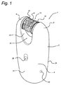
図1は、本発明の第1の実施例による脱毛装置1の斜視図を示す。脱毛装置1は、ハンドル4、該ハンドルから延在し該ハンドルとの間に開いた顎部10を形成する第1及び第2の肩部6、8と、を定義する筐体2を有する。複数の毛抜き要素14を有する毛抜き部12が、顎部10内で回転するよう装着される。毛抜き部12は、それぞれが第1及び第2の肩部6、8により支持された、第1及び第2の端16、18を持つ。毛抜き部12は、開口20が筐体2の前側22から後側24まで装置1を通して形成されるように、ハンドル4から距離をおいて装着される。筐体2にはまた、作動スイッチ26と、充電の目的のための接点28と、が前側22に備えられる。
FIG. 1 shows a perspective view of a
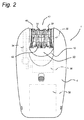
図2は、図1の装置1の前面図を示す。図示されるように、毛抜き部12は、外周に形成された毛抜き要素14を持つ複数のディスク30を有する。ディスク30は、シャフト32により支持され、筐体2に配置された適切な伝達部34によって駆動される。また、モータ36及び充電可能なバッテリ38も、筐体内に破線で示されている。シャフト32は僅かに湾曲させられ、顎部10内の筐体2の前側22へと僅かに向けて形成された挟み領域40にディスク30を収束させる。ディスク30は、開口20内に形成された解放領域42において再び広がる。毛抜き部12の動作の更なる詳細は国際特許出願公開WO2006/117755A1に見出すことができ、該文献はその全体がここで参照によって本明細に組み込まれたものとする。本発明はディスクベースの毛抜き部に関連して説明されるが、必要とされる毛の挟み及び引き抜きを実現できる同様ないずれの毛抜き機構にも、本原理は等しく適用できることは理解されるであろう。動作の間、回転する毛抜き部12は、ユーザの皮膚に接触させられる。挟み領域40において毛が把持され、毛抜き部12が更に回転すると皮膚から引き抜かれる。毛抜き部が筐体に埋め込まれた従来の設計においては、毛は解放される前に下向きに筐体の凹部へと回転する。本発明の設計によれば、解放領域42が開口20に配置され、解放の際に、毛抜き部12から毛が自由に落ちる。ハンドル4と毛抜き部12との間に形成された開口20が比較的大きいため、比較的長い又は弾力のある毛であっても脱出することができ、該装置は容易に綺麗に保たれることができる。更に、毛抜き部12とハンドル4との間の開いた空間のため、この位置において皮膚の皺が挟まれない。
FIG. 2 shows a front view of the
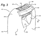
図3は、本発明の第2の実施例による装置101の上部の後方斜視図を示す。第1の実施例と同様の要素は、ここでは100だけ大きな同一の参照番号を付与されている。
FIG. 3 shows a rear perspective view of the upper part of the
第2の実施例の装置101は、第1の肩部106から第2の肩部108までに亘り延在する、筐体102の上方後側124に備えられた、離隔棒148の存在により、第1の実施例とは異なっている。棒148は、毛抜き部112から僅かに離隔され、毛抜き部112の回転方向Rにおいて挟み領域140の僅かに前方の位置に配置される。装置101はまた、筐体102の後側124における開口120が前側122よりも大きく、それにより開口120の下側面150が後側124に向けて下向きに傾斜している点においても異なっている。
Due to the presence of a separating
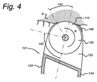
図4は、使用の間、皮膚Sに装置101が接触した状態の、線IV−IVに沿ってとられた図3の装置101の断面図を示す。本図において、挟み領域140は、約45°の角度をカバーしているのが示されている。回転方向Rにおいて挟み領域140に後続するのが、解放領域142である。理解されるであろうように、挟み領域140は、毛が挟まれる領域として示されている。しかしながら、挟み領域140の前に、ディスク130の毛抜き要素114が閉じ始め、例えば圧力がかけられている場合には、既に皮膚の皺を捉え得る。棒148は、もし該棒がなければ皮膚の挟みが起こり得るような毛抜き部112の部分を、効果的にカバーしている。更に、棒148は、使用の間のユーザのためのガイドを提供し、皮膚Sから毛抜き部112を離隔させるように機能する。
FIG. 4 shows a cross-sectional view of the
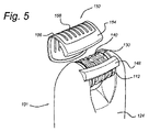
図5は、キャップ152の形をとる保護部を備えた、後側124からみた図3の装置101の斜視図を示す。キャップ152は、金属のフォイル156を担持するプラスチック枠154の形をとり、該金属のフォイルが挟み領域140を略カバーしている。フォイル156は、毛抜き部112のディスク130に平行に延在するスロット158を持つ。キャップ152は、脱毛処理の対する更なる制御をもたらし、スロット158に対する毛抜き部112の露出領域を制限する。このことは、該キャップがなければ皮膚の皺が挟まれてしまうような制約ある領域における装置101の使用を、より容易化する。
FIG. 5 shows a perspective view of the
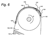
図6は、キャップ152が挟み領域140の上で保持される態様を示す、図4と同様の断面図を示す。図示されるように、枠154は後側に棒148と係合するクリップ160を持つ。枠154は弾力性であり、肩部106、108と係合するように曲げられている。当業者は、該フレームを適所に保持するため筐体102に更なる固定要素が備えられても良いことを、よく理解するであろう。
FIG. 6 shows a cross-sectional view similar to FIG. 4, showing the manner in which the
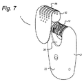
図7は、第1の実施例の装置1に適用されることができる代替の保護部52を示す。該保護部52は、筐体2の前面22の上に更に延在し、開口20を完全にカバーする。図5のキャップ152の場合におけるように、保護部52はスロット58を持ち、該スロットを通して毛が毛抜き部12により係合されることができる。本実施例においては、保護部52は、磁性材料から形成され、磁力により筐体2に保持される。
FIG. 7 shows an
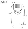
図8は、保護部52が適所に配置された、後側24からの図1の装置を示す。図示されるように、開口20は、抜き取られた毛が出ることができるように、筐体2の後側24に開口20が露出させられている。当業者は、毛を集めるための閉じた室を形成するために該開口の後側を閉じることもできることを、理解するであろう。
FIG. 8 shows the device of FIG. 1 from the
斯くして、本発明は、以上に議論された特定の実施例を参照しながら説明された。これら実施例に対しては、当業者には良く知られた種々の変更及び代替が可能であることは、理解されるであろう。とりわけ、毛抜き部の構造は、模式的に図示された設計とは異なっていても良い。 Thus, the present invention has been described with reference to the specific embodiments discussed above. It will be understood that various modifications and substitutions well known to those skilled in the art are possible for these embodiments. In particular, the structure of the tweezers may be different from the design schematically shown.
以上に説明されたものに加え、本発明の精神及び範囲から逸脱することなく、ここで説明された構造及び技術に対して多くの変更が為され得る。従って、特定の実施例が説明されたが、これらは単に例であり、本発明の範囲を限定するものではない。 In addition to those described above, many modifications can be made to the structures and techniques described herein without departing from the spirit and scope of the invention. Accordingly, while specific embodiments have been described, these are merely examples and are not intended to limit the scope of the invention.
Claims (15)
ハンドルと、前記ハンドルから延在する第1の肩部及び第2の肩部であって前記第1の肩部と前記第2の肩部との間に開いた顎部を形成する第1の肩部及び第2の肩部と、を定義する、筐体と、
軸、第1及び第2の端部、並びに少なくとも一対の毛抜き要素を持つ毛抜き部であって、前記毛抜き部は、使用の間に前記軸のまわりに回転するよう装着され、前記毛抜き部の周縁部において毛が挟まれ得る少なくとも1つの挟み領域を定義し、前記毛抜き部は、前記第1及び第2の端部が、それぞれ前記第1及び第2の肩部によって支持されるよう、前記顎部に装着された、毛抜き部と、
前記筐体内に配置され、前記毛抜き部を前記軸のまわりに回転させる回転運動をもたらすように構成された、駆動機構と、
を有し、
前記毛抜き部は、前記筐体の前側から前記筐体の後側まで前記装置を通して開口が形成されるようなものとなる前記ハンドルからの距離において前記肩部間に装着され、前記開口は、前記ハンドル、前記肩部及び前記毛抜き部によって境界付けられる、脱毛装置。 A hair removal device for removing hair from the skin by pinching, pulling and releasing the hair, wherein the hair removal device comprises:
A handle and a first shoulder and a second shoulder extending from the handle, the first shoulder forming an open jaw between the first shoulder and the second shoulder; A housing defining a shoulder and a second shoulder;
A tweezers having a shaft, first and second ends, and at least a pair of tweezer elements, wherein the tweezers are mounted to rotate about the shaft during use, and the perimeter of the tweezers Defining at least one pinching region in which hair can be pinched at the portion, wherein the tweezers are such that the first and second ends are supported by the first and second shoulders, respectively. The tweezers attached to the part,
A drive mechanism disposed within the housing and configured to provide a rotational motion that rotates the tweezers about the axis;
Have
The tweezers are mounted between the shoulders at a distance from the handle such that an opening is formed through the device from the front side of the housing to the rear side of the housing, An epilation device bounded by a handle, the shoulder and the tweezer.
Applications Claiming Priority (3)
| Application Number | Priority Date | Filing Date | Title |
|---|---|---|---|
| US201261701751P | 2012-09-17 | 2012-09-17 | |
| US61/701,751 | 2012-09-17 | ||
| PCT/IB2013/058219 WO2014041459A1 (en) | 2012-09-17 | 2013-09-02 | Epilating device having open configuration |
Publications (2)
| Publication Number | Publication Date |
|---|---|
| JP2015528362A true JP2015528362A (en) | 2015-09-28 |
| JP2015528362A5 JP2015528362A5 (en) | 2016-10-20 |
Family
ID=49304039
Family Applications (1)
| Application Number | Title | Priority Date | Filing Date |
|---|---|---|---|
| JP2015531663A Pending JP2015528362A (en) | 2012-09-17 | 2013-09-02 | Epilation device with open configuration |
Country Status (8)
| Country | Link |
|---|---|
| US (1) | US9655428B2 (en) |
| EP (1) | EP2895025B1 (en) |
| JP (1) | JP2015528362A (en) |
| CN (1) | CN104661558B (en) |
| BR (1) | BR112015005477B1 (en) |
| RU (1) | RU2639638C2 (en) |
| TR (1) | TR201815052T4 (en) |
| WO (1) | WO2014041459A1 (en) |
Citations (7)
| Publication number | Priority date | Publication date | Assignee | Title |
|---|---|---|---|---|
| JPS63277005A (en) * | 1987-03-04 | 1988-11-15 | ヘア リムーバー リミティド | Body hair removing apparatus |
| JPH0739421A (en) * | 1993-07-27 | 1995-02-10 | Matsushita Electric Works Ltd | Depilator |
| JPH09510127A (en) * | 1994-03-16 | 1997-10-14 | ブラウン、アクチエンゲゼルシャフト | Epilator |
| JP2006509565A (en) * | 2002-12-14 | 2006-03-23 | ブラウン ゲーエムベーハー | Attachment for epilator |
| JP2007061424A (en) * | 2005-08-31 | 2007-03-15 | Toshiba Battery Co Ltd | Illuminated portable mirror |
| JP2007517639A (en) * | 2005-02-06 | 2007-07-05 | ライシェン リウ | Electric hair remover |
| JP3172669U (en) * | 2011-10-17 | 2012-01-05 | 光▲いぇ▼科技股▲ふん▼有限公司 | Light solidification device with magnetic suction slide cover |
Family Cites Families (18)
| Publication number | Priority date | Publication date | Assignee | Title |
|---|---|---|---|---|
| US1519504A (en) | 1924-01-07 | 1924-12-16 | Pando Edgardo | Electric shaving machine |
| IL82002A0 (en) | 1987-03-25 | 1987-10-20 | Gen Ideas & Prod Ltd | Depilatory device |
| US5207689A (en) * | 1988-02-09 | 1993-05-04 | Braun Aktiengesellschaft | Depilating appliance |
| JPH0489207U (en) * | 1990-12-10 | 1992-08-04 | ||
| IL103073A (en) | 1991-09-10 | 1995-11-27 | Philips Electronics Nv | Disc-type depilation apparatus |
| IL103071A (en) * | 1991-09-10 | 1995-11-27 | Philips Electronics Nv | Disc-type depilation apparatus |
| DE69230781T2 (en) * | 1991-12-23 | 2000-09-21 | Koninkl Philips Electronics Nv | Hair removal device with a twisting effect |
| DE4428892A1 (en) * | 1994-08-18 | 1996-02-22 | Braun Ag | Epilation device with a multi-shell housing |
| DE19809436A1 (en) * | 1998-03-05 | 1999-09-09 | Braun Gmbh | Attachment for a device for plucking hair from human skin |
| US5976157A (en) * | 1998-07-09 | 1999-11-02 | K.I.S. Ltd. | Hair removal device with disc assembly |
| USD438341S1 (en) | 1999-11-10 | 2001-02-27 | Braun Gmbh | Depilator |
| US20040087973A1 (en) * | 2002-08-26 | 2004-05-06 | Golnaz Shobeiri | Multiple-hair removal device and method of use |
| IL159483A0 (en) * | 2003-12-21 | 2004-06-01 | Epilady 2000 Llc | Hair removal system |
| CN2722646Y (en) * | 2004-07-27 | 2005-09-07 | 刘莱生 | Electric hair picker |
| US20060218793A1 (en) | 2005-03-31 | 2006-10-05 | Wheel Technology Ltd. | Electric razor with helical filament winding |
| DE602006011732D1 (en) | 2005-05-02 | 2010-03-04 | Koninkl Philips Electronics Nv | DISC FOR EPILATOR WITH DISC ASSEMBLY |
| US20070239174A1 (en) * | 2006-04-06 | 2007-10-11 | Francis Yiu | Epilator with Glide Tweezers |
| CN101219011B (en) * | 2007-01-12 | 2011-12-28 | 游图明 | Plucker with improved structure |
-
2013
- 2013-09-02 US US14/426,518 patent/US9655428B2/en active Active
- 2013-09-02 CN CN201380048121.7A patent/CN104661558B/en active Active
- 2013-09-02 EP EP13773406.7A patent/EP2895025B1/en active Active
- 2013-09-02 TR TR2018/15052T patent/TR201815052T4/en unknown
- 2013-09-02 JP JP2015531663A patent/JP2015528362A/en active Pending
- 2013-09-02 RU RU2015114248A patent/RU2639638C2/en active
- 2013-09-02 BR BR112015005477-3A patent/BR112015005477B1/en not_active IP Right Cessation
- 2013-09-02 WO PCT/IB2013/058219 patent/WO2014041459A1/en not_active Ceased
Patent Citations (7)
| Publication number | Priority date | Publication date | Assignee | Title |
|---|---|---|---|---|
| JPS63277005A (en) * | 1987-03-04 | 1988-11-15 | ヘア リムーバー リミティド | Body hair removing apparatus |
| JPH0739421A (en) * | 1993-07-27 | 1995-02-10 | Matsushita Electric Works Ltd | Depilator |
| JPH09510127A (en) * | 1994-03-16 | 1997-10-14 | ブラウン、アクチエンゲゼルシャフト | Epilator |
| JP2006509565A (en) * | 2002-12-14 | 2006-03-23 | ブラウン ゲーエムベーハー | Attachment for epilator |
| JP2007517639A (en) * | 2005-02-06 | 2007-07-05 | ライシェン リウ | Electric hair remover |
| JP2007061424A (en) * | 2005-08-31 | 2007-03-15 | Toshiba Battery Co Ltd | Illuminated portable mirror |
| JP3172669U (en) * | 2011-10-17 | 2012-01-05 | 光▲いぇ▼科技股▲ふん▼有限公司 | Light solidification device with magnetic suction slide cover |
Also Published As
| Publication number | Publication date |
|---|---|
| BR112015005477B1 (en) | 2021-06-22 |
| TR201815052T4 (en) | 2018-11-21 |
| WO2014041459A1 (en) | 2014-03-20 |
| EP2895025B1 (en) | 2018-08-08 |
| BR112015005477A2 (en) | 2017-07-04 |
| RU2015114248A (en) | 2016-11-10 |
| EP2895025A1 (en) | 2015-07-22 |
| RU2639638C2 (en) | 2017-12-21 |
| US20150237986A1 (en) | 2015-08-27 |
| US9655428B2 (en) | 2017-05-23 |
| CN104661558A (en) | 2015-05-27 |
| CN104661558B (en) | 2019-02-15 |
Similar Documents
| Publication | Publication Date | Title |
|---|---|---|
| US20200337432A1 (en) | Hair removal apparatus | |
| EP2651260B1 (en) | Hair styling device | |
| CN1196450C (en) | Hair removal device with vibrating device | |
| CN104703503B (en) | Grainer | |
| EP0373032B1 (en) | Depilation apparatus | |
| EP0272269B1 (en) | Depilation apparatus | |
| JPH0779731B2 (en) | Hair removal device | |
| JPH0329605A (en) | Removing method for hair and device therefor | |
| JP5805785B2 (en) | Improved tweezer head for hair removal | |
| JPH02295510A (en) | Removing apparatus for hair | |
| TW557208B (en) | Molting apparatus | |
| JP4511366B2 (en) | Attachment for epilator | |
| JP2015528362A (en) | Epilation device with open configuration | |
| CN100482121C (en) | Epilating apparatus | |
| CN104640475B (en) | Epilator with exposed tweezers | |
| JP2012075752A (en) | Scissors | |
| FR2586538A1 (en) | Hair-removing apparatus | |
| JP3422085B2 (en) | Hair removal device | |
| CN104661561B (en) | With the balanced grainer for pivoting pincers | |
| JP2015528362A5 (en) | ||
| HK1183214B (en) | Hair styling device | |
| JPH08228824A (en) | Hair remover |
Legal Events
| Date | Code | Title | Description |
|---|---|---|---|
| A521 | Request for written amendment filed |
Free format text: JAPANESE INTERMEDIATE CODE: A523 Effective date: 20160830 |
|
| A621 | Written request for application examination |
Free format text: JAPANESE INTERMEDIATE CODE: A621 Effective date: 20160830 |
|
| RD04 | Notification of resignation of power of attorney |
Free format text: JAPANESE INTERMEDIATE CODE: A7424 Effective date: 20170214 |
|
| A977 | Report on retrieval |
Free format text: JAPANESE INTERMEDIATE CODE: A971007 Effective date: 20171013 |
|
| A131 | Notification of reasons for refusal |
Free format text: JAPANESE INTERMEDIATE CODE: A131 Effective date: 20171026 |
|
| A601 | Written request for extension of time |
Free format text: JAPANESE INTERMEDIATE CODE: A601 Effective date: 20171225 |
|
| A02 | Decision of refusal |
Free format text: JAPANESE INTERMEDIATE CODE: A02 Effective date: 20180802 |
|
| A521 | Request for written amendment filed |
Free format text: JAPANESE INTERMEDIATE CODE: A523 Effective date: 20181128 |
|
| A911 | Transfer to examiner for re-examination before appeal (zenchi) |
Free format text: JAPANESE INTERMEDIATE CODE: A911 Effective date: 20181205 |
|
| A912 | Re-examination (zenchi) completed and case transferred to appeal board |
Free format text: JAPANESE INTERMEDIATE CODE: A912 Effective date: 20190208 |