JP2015523938A - Boxes made of cardboard sheet material, blanks or blank assemblies, and methods and apparatus for forming such boxes - Google Patents
Boxes made of cardboard sheet material, blanks or blank assemblies, and methods and apparatus for forming such boxes Download PDFInfo
- Publication number
- JP2015523938A JP2015523938A JP2015517826A JP2015517826A JP2015523938A JP 2015523938 A JP2015523938 A JP 2015523938A JP 2015517826 A JP2015517826 A JP 2015517826A JP 2015517826 A JP2015517826 A JP 2015517826A JP 2015523938 A JP2015523938 A JP 2015523938A
- Authority
- JP
- Japan
- Prior art keywords
- box
- blank
- cut
- panels
- main
- Prior art date
- Legal status (The legal status is an assumption and is not a legal conclusion. Google has not performed a legal analysis and makes no representation as to the accuracy of the status listed.)
- Pending
Links
- 239000000463 material Substances 0.000 title claims abstract description 15
- 238000000034 method Methods 0.000 title claims abstract description 11
- 230000000712 assembly Effects 0.000 title 1
- 238000000429 assembly Methods 0.000 title 1
- 238000005520 cutting process Methods 0.000 claims description 54
- 238000003825 pressing Methods 0.000 claims description 7
- 238000004026 adhesive bonding Methods 0.000 claims description 4
- 238000004804 winding Methods 0.000 claims description 2
- 239000000123 paper Substances 0.000 description 14
- 239000000853 adhesive Substances 0.000 description 6
- 230000001070 adhesive effect Effects 0.000 description 6
- 230000006835 compression Effects 0.000 description 5
- 238000007906 compression Methods 0.000 description 5
- 238000012856 packing Methods 0.000 description 5
- 230000015572 biosynthetic process Effects 0.000 description 4
- 239000006260 foam Substances 0.000 description 4
- 239000005022 packaging material Substances 0.000 description 4
- 238000005304 joining Methods 0.000 description 2
- 241000722921 Tulipa gesneriana Species 0.000 description 1
- 239000011248 coating agent Substances 0.000 description 1
- 238000000576 coating method Methods 0.000 description 1
- 230000000295 complement effect Effects 0.000 description 1
- 238000010276 construction Methods 0.000 description 1
- 230000000694 effects Effects 0.000 description 1
- 238000005187 foaming Methods 0.000 description 1
- 239000012943 hotmelt Substances 0.000 description 1
- 238000004519 manufacturing process Methods 0.000 description 1
- 238000004806 packaging method and process Methods 0.000 description 1
Images


Classifications
-
- B—PERFORMING OPERATIONS; TRANSPORTING
- B65—CONVEYING; PACKING; STORING; HANDLING THIN OR FILAMENTARY MATERIAL
- B65D—CONTAINERS FOR STORAGE OR TRANSPORT OF ARTICLES OR MATERIALS, e.g. BAGS, BARRELS, BOTTLES, BOXES, CANS, CARTONS, CRATES, DRUMS, JARS, TANKS, HOPPERS, FORWARDING CONTAINERS; ACCESSORIES, CLOSURES, OR FITTINGS THEREFOR; PACKAGING ELEMENTS; PACKAGES
- B65D5/00—Rigid or semi-rigid containers of polygonal cross-section, e.g. boxes, cartons or trays, formed by folding or erecting one or more blanks made of paper
- B65D5/02—Rigid or semi-rigid containers of polygonal cross-section, e.g. boxes, cartons or trays, formed by folding or erecting one or more blanks made of paper by folding or erecting a single blank to form a tubular body with or without subsequent folding operations, or the addition of separate elements, to close the ends of the body
- B65D5/0209—Rigid or semi-rigid containers of polygonal cross-section, e.g. boxes, cartons or trays, formed by folding or erecting one or more blanks made of paper by folding or erecting a single blank to form a tubular body with or without subsequent folding operations, or the addition of separate elements, to close the ends of the body the tubular body having a curved or partially curved cross-section
-
- B—PERFORMING OPERATIONS; TRANSPORTING
- B65—CONVEYING; PACKING; STORING; HANDLING THIN OR FILAMENTARY MATERIAL
- B65D—CONTAINERS FOR STORAGE OR TRANSPORT OF ARTICLES OR MATERIALS, e.g. BAGS, BARRELS, BOTTLES, BOXES, CANS, CARTONS, CRATES, DRUMS, JARS, TANKS, HOPPERS, FORWARDING CONTAINERS; ACCESSORIES, CLOSURES, OR FITTINGS THEREFOR; PACKAGING ELEMENTS; PACKAGES
- B65D5/00—Rigid or semi-rigid containers of polygonal cross-section, e.g. boxes, cartons or trays, formed by folding or erecting one or more blanks made of paper
- B65D5/32—Rigid or semi-rigid containers of polygonal cross-section, e.g. boxes, cartons or trays, formed by folding or erecting one or more blanks made of paper having bodies formed by folding and interconnecting two or more blanks each blank forming a body part, whereby each body part comprises at least one outside face of the box, carton or tray
-
- B—PERFORMING OPERATIONS; TRANSPORTING
- B31—MAKING ARTICLES OF PAPER, CARDBOARD OR MATERIAL WORKED IN A MANNER ANALOGOUS TO PAPER; WORKING PAPER, CARDBOARD OR MATERIAL WORKED IN A MANNER ANALOGOUS TO PAPER
- B31B—MAKING CONTAINERS OF PAPER, CARDBOARD OR MATERIAL WORKED IN A MANNER ANALOGOUS TO PAPER
- B31B50/00—Making rigid or semi-rigid containers, e.g. boxes or cartons
- B31B50/60—Uniting opposed surfaces or edges; Taping
- B31B50/62—Uniting opposed surfaces or edges; Taping by adhesives
-
- B—PERFORMING OPERATIONS; TRANSPORTING
- B65—CONVEYING; PACKING; STORING; HANDLING THIN OR FILAMENTARY MATERIAL
- B65D—CONTAINERS FOR STORAGE OR TRANSPORT OF ARTICLES OR MATERIALS, e.g. BAGS, BARRELS, BOTTLES, BOXES, CANS, CARTONS, CRATES, DRUMS, JARS, TANKS, HOPPERS, FORWARDING CONTAINERS; ACCESSORIES, CLOSURES, OR FITTINGS THEREFOR; PACKAGING ELEMENTS; PACKAGES
- B65D5/00—Rigid or semi-rigid containers of polygonal cross-section, e.g. boxes, cartons or trays, formed by folding or erecting one or more blanks made of paper
- B65D5/02—Rigid or semi-rigid containers of polygonal cross-section, e.g. boxes, cartons or trays, formed by folding or erecting one or more blanks made of paper by folding or erecting a single blank to form a tubular body with or without subsequent folding operations, or the addition of separate elements, to close the ends of the body
-
- B—PERFORMING OPERATIONS; TRANSPORTING
- B65—CONVEYING; PACKING; STORING; HANDLING THIN OR FILAMENTARY MATERIAL
- B65D—CONTAINERS FOR STORAGE OR TRANSPORT OF ARTICLES OR MATERIALS, e.g. BAGS, BARRELS, BOTTLES, BOXES, CANS, CARTONS, CRATES, DRUMS, JARS, TANKS, HOPPERS, FORWARDING CONTAINERS; ACCESSORIES, CLOSURES, OR FITTINGS THEREFOR; PACKAGING ELEMENTS; PACKAGES
- B65D5/00—Rigid or semi-rigid containers of polygonal cross-section, e.g. boxes, cartons or trays, formed by folding or erecting one or more blanks made of paper
- B65D5/32—Rigid or semi-rigid containers of polygonal cross-section, e.g. boxes, cartons or trays, formed by folding or erecting one or more blanks made of paper having bodies formed by folding and interconnecting two or more blanks each blank forming a body part, whereby each body part comprises at least one outside face of the box, carton or tray
- B65D5/326—Rigid or semi-rigid containers of polygonal cross-section, e.g. boxes, cartons or trays, formed by folding or erecting one or more blanks made of paper having bodies formed by folding and interconnecting two or more blanks each blank forming a body part, whereby each body part comprises at least one outside face of the box, carton or tray at least one container body part formed by folding a single blank to a permanently assembled tube
- B65D5/327—Rigid or semi-rigid containers of polygonal cross-section, e.g. boxes, cartons or trays, formed by folding or erecting one or more blanks made of paper having bodies formed by folding and interconnecting two or more blanks each blank forming a body part, whereby each body part comprises at least one outside face of the box, carton or tray at least one container body part formed by folding a single blank to a permanently assembled tube at least two container body parts, each formed by folding a single blank to a permanently assembled tube
- B65D5/328—Rigid or semi-rigid containers of polygonal cross-section, e.g. boxes, cartons or trays, formed by folding or erecting one or more blanks made of paper having bodies formed by folding and interconnecting two or more blanks each blank forming a body part, whereby each body part comprises at least one outside face of the box, carton or tray at least one container body part formed by folding a single blank to a permanently assembled tube at least two container body parts, each formed by folding a single blank to a permanently assembled tube and the tubular body parts being alligned axially to form a container
-
- B—PERFORMING OPERATIONS; TRANSPORTING
- B31—MAKING ARTICLES OF PAPER, CARDBOARD OR MATERIAL WORKED IN A MANNER ANALOGOUS TO PAPER; WORKING PAPER, CARDBOARD OR MATERIAL WORKED IN A MANNER ANALOGOUS TO PAPER
- B31B—MAKING CONTAINERS OF PAPER, CARDBOARD OR MATERIAL WORKED IN A MANNER ANALOGOUS TO PAPER
- B31B50/00—Making rigid or semi-rigid containers, e.g. boxes or cartons
- B31B50/26—Folding sheets, blanks or webs
- B31B50/28—Folding sheets, blanks or webs around mandrels, e.g. for forming bottoms
- B31B50/282—Folding sheets, blanks or webs around mandrels, e.g. for forming bottoms involving stripping-off formed boxes from mandrels
Abstract
本発明は、箱、ブランクまたはブランクアセンブリ、ならびに多角形の断面を有する段ボール紙シート材料製の箱を形成するための方法および装置に関するものである。前記箱は、少なくとも4つの主要矩形パネルを含み、箱の底面および/または上面を少なくとも部分的に形成するのに適した、少なくとも一連のフラップを備え、前記主要側面パネルのうちの少なくとも2つが、フラップのない切断隅を形成する中間パネルを介して主要中央パネルに接続される、ストラップを含む。切断隅の少なくとも2つは折り目によって共に、または、隣接する主要パネルに接続される、少なくとも2つの矩形の切断面部分によって形成され、前記切断面部分は、3mmから20mmの間の幅を有する。The present invention relates to a box, a blank or blank assembly, and a method and apparatus for forming a box made of corrugated paper sheet material having a polygonal cross section. The box includes at least four main rectangular panels and comprises at least a series of flaps suitable for at least partially forming the bottom and / or top of the box, wherein at least two of the main side panels are It includes a strap connected to the main central panel through an intermediate panel that forms a cut corner without flaps. At least two of the cut corners are formed by at least two rectangular cut surface portions connected together by creases or to adjacent main panels, said cut surface portions having a width between 3 mm and 20 mm.
Description
本発明は、少なくとも4つの主要矩形パネルを含み、かつ、少なくとも部分的に箱の底面および/または上面を形成することが可能な少なくとも一連のフラップを備えるベルトを含み、主要側面パネルのうちの少なくとも2つが、中間パネルによって主要中央パネルに接続されて、フラップを有さない切断隅を形成する、多角形の断面を有する段ボール紙シート材料の箱に関するものである。 The present invention includes a belt comprising at least a series of flaps including at least four major rectangular panels and at least partially forming a bottom and / or top surface of a box, wherein at least one of the major side panels The second relates to a box of corrugated paper sheet material having a polygonal cross section that is connected to the main central panel by an intermediate panel to form a cut corner without a flap.
本発明はまた、ブランクまたはブランクのセット、ならびにかかる箱を得られるようにする方法および装置に関するものである。 The invention also relates to a blank or a set of blanks, as well as a method and apparatus for obtaining such a box.
排他的ではないが、特に重要な用途は、マンドレルのまわりに形成され、円筒形の製品、たとえば、ボトルを収容するために設けられる箱の分野を含む。 A non-exclusive but particularly important application includes the field of boxes formed around mandrels and provided for receiving cylindrical products such as bottles.
丸みを帯びた製品を収容するために利用できる内容積を最適化するために構成された箱が、既に公知である。 Boxes designed to optimize the internal volume available for accommodating rounded products are already known.
たとえば、8つの面、つまり、4つの主要な面、およびより小さい寸法を有し、箱の内側に位置する製品の形状により良好に適合できるようにする4つの中間面を有する箱がある。 For example, there is a box with 8 faces, 4 major faces, and 4 intermediate faces that have smaller dimensions and allow a better fit to the shape of the product located inside the box.
このような梱包材はより良好な耐圧縮性を有し、マンドレルのまわりで容易に生産することができるが、2つの溝(下記では折り線とも称する)および/または垂直な折り目の間に存在しなければならない特定の距離を必要とするため、それらは大きい寸法であり続ける切断面の形状を最適化できるようにしない。 Such packaging has better compression resistance and can be easily produced around the mandrel, but is present between two grooves (also referred to below as fold lines) and / or vertical folds They do not allow to optimize the shape of the cut surfaces that remain large in size because they require specific distances that must be done.
また、段ボール紙シートも、特に「巻き付け」梱包材として公知の梱包材分野で、比較的柔軟で、丸みを帯びたアングルを有するものも、公知である。 Corrugated cardboard sheets are also known in the packaging material field, particularly known as “wrapping” packaging materials, which are relatively flexible and have rounded angles.
しかしながら、それらの梱包材は、耐圧縮性に乏しく、形成するのが困難である。 However, these packing materials have poor compression resistance and are difficult to form.
本発明の目的は、多角形の断面を有する段ボール紙シート材料の箱を提供することにあって、より良好な耐圧縮性によって、特に公知の箱が欠点を克服できるようにすることにおいて、ならびに、その角度が、容易、自動、および効果的な方法で、完全に丸みを帯びていないが、円の1/4に類似する、自動梱包材形成をできるようにすることにおいて、すでに公知の箱よりも、より良好に実用的要件に準拠する。 The object of the present invention is to provide a box of corrugated paper sheet material having a polygonal cross-section, in order to allow the known box to overcome the drawbacks by means of better compression resistance, and Boxes already known in the art to enable automatic packing material formation, whose angle is not completely rounded in an easy, automatic and effective manner, but is similar to a quarter of a circle Better to comply with practical requirements.
そうすることで、それが有する品質に関して高速かつ反復して生産することができ、良好な耐圧縮性を有する箱の利点を組み合わせることが可能である。有利なことに、壁面および/または隅は、より良好な耐圧性を有し、特に、特定の高さにわたって剛性の片を含むその性質の事実の結果として、同様に特定の高さを有する壁面および/または隅と組み合わせられる一方で、梱包材が、特に楕円および/または丸い円筒形の製品、たとえばボトルを含むときに、それが収容できる製品のそれとできるだけ類似した形状を有することができるようにする。 By doing so, it can be produced quickly and repeatedly with regard to the quality it has, and it is possible to combine the advantages of a box with good compression resistance. Advantageously, the walls and / or corners have a better pressure resistance, in particular walls with a certain height as a result of the fact of their nature, including the rigid pieces over a certain height. And / or combined with corners, so that the packaging material can have a shape as similar as possible to that of the product it can accommodate, especially when it includes an elliptical and / or round cylindrical product, such as a bottle. To do.
そのために、本発明は実質的に、多角形の断面を有する段ボール紙シート材料の箱であって、
少なくとも4つの主要矩形パネルを含み、少なくとも部分的に箱の底面および/または上面を形成することが可能な少なくとも一連のフラップを備えるベルトであって、主要側面パネルのうちの少なくとも2つが中間パネルによって主要中央パネルに接続され、フラップを有さない切断隅を形成することを含み、
少なくとも2つの切断隅は折り目によって、互いに、または隣接する主要パネルに接続される少なくとも2つの切断面の矩形部分によって形成されること、切断面の部分が、3mmから20mmの間の幅を有すること、および少なくとも2つの対向する主要パネルが、異なる幅を有することを特徴とする箱を提案する。
To that end, the present invention is a box of corrugated paper sheet material having a substantially polygonal cross section, comprising:
A belt comprising at least a series of flaps including at least four main rectangular panels and capable of at least partially forming a bottom and / or top surface of the box, wherein at least two of the main side panels are defined by intermediate panels Forming a cut corner connected to the main central panel and having no flaps;
The at least two cut corners are formed by creases, by a rectangular part of at least two cut faces connected to each other or to the adjacent main panel, the cut face part having a width between 3 mm and 20 mm And a box characterized in that at least two opposing main panels have different widths.
このため、それらの梱包材を折ることは、寸法の積み重ねおよび隅の形成を可能にする、異なる幅を有する少なくとも2つの対向する主要パネルをマンドレルのまわりに巻き付けることによってもたらされる。 For this reason, the folding of these packing materials is effected by wrapping around the mandrel at least two opposing main panels with different widths, which allow the stacking of dimensions and the formation of corners.
結果として、互いに近い距離に位置する矩形切断面を含むこのような多ファセットの箱の構築は、許容値で箱の耐圧縮性を保持できるようにする一方で、異なる数、たとえば、2から9ファセットであってよい、その多ファセットの結果として、含まれる製品に梱包材が完全に適合する可能性を可能にする。 As a result, the construction of such a multi-faceted box that includes rectangular cut faces that are located at a distance close to each other allows the box to retain the compression resistance of the box at an acceptable value, while a different number, eg, 2 to 9 As a result of its multi-faceted, which may be faceted, it allows the possibility of the packaging material being a perfect fit for the contained product.
結果として、箱の切断隅は、10までの単純で近接した折り線または折り目を含む。 As a result, the cut corner of the box contains up to 10 simple, close fold lines or creases.
そのために、および自動的な方法で、互いに近い折り線を折ることを可能にするために、並んだ(短距離をおいて位置する)折り線をつぶさずに、それらを形成できるツールを構成する必要があった。これは、特に、並んだ(円錐台形状)部分をつぶさないように設けられる折り線を形成するため、または折り線が互いに近すぎる場合、さもなければ得ることが不可能な、引き続き正しく折ることができるようにするために、いかなる発泡体もなしですますことによって、および折り線を穿孔することによって、ブレードの発泡(発泡体、たとえば、プラスチック材料の層で被覆)の結果としてなされる。 To that end, and in an automatic way, to make it possible to fold fold lines close to each other, construct a tool that can form them without breaking side-by-side fold lines (located at short distances) There was a need. This is especially true to form a fold line that is provided so as not to crush the side-by-side (conical frusto-conical) portions, or if the fold lines are too close to each other, then continue to fold correctly, otherwise impossible to obtain Is made as a result of foaming of the blade (coating with a layer of foam, eg plastic material), by eliminating any foam and by perforating the fold lines.
有利な実施形態において、用途は、次の構成の1つおよび/またはその他で、さらに、および/または同様になされる:
− 切断面の部分の幅が10mm未満またはそれに等しい、たとえば、8mmまたは5mm未満である;
− 各主要パネルが、切断隅によってその隣接する主要パネルに接続される;
− 少なくとも2つの切断隅が、同じ高さを有し、それぞれ平行な折り目によって互いに接続される、少なくとも3つの切断面の矩形部分によってそれぞれが形成される;
− 少なくとも2つの切断隅が、同じ高さを有し、それぞれ折り目によって互いに接続される、少なくとも4つの切断面の矩形部分によってそれぞれが形成される;
− 少なくとも2つの切断隅が、折り目によって互いに接続される、少なくとも8つの切断面の矩形部分によって形成される;
− 第1の対向する主要パネルのうちの2つが第1の所定の高さを有し、他方の2つの第2の対向する主要パネルが第2の所定の高さを有し、第1の高さが第2の高さとは異なる。
その差は、たとえば、段ボール紙の2つの厚み未満、たとえば、厚みまたは半分の厚みである。厚み2mm未満の微小な溝を持つ段ボール紙(適用できる国際分類におけるカテゴリーE)について、3つの高さは、同一であってよい。他方で、タイプB(厚み3mm)またはC(厚み4mm)の、より従来通りの溝については、異なる高さが設けられてもよい。
In advantageous embodiments, the application is made in one and / or the other of the following configurations, and / or similarly:
The width of the section of the cut surface is less than or equal to 10 mm, for example less than 8 mm or 5 mm;
Each main panel is connected to its adjacent main panel by a cut corner;
-At least two cut corners are each formed by a rectangular part of at least three cut faces, having the same height, each connected to each other by parallel folds;
-At least two cutting corners are each formed by a rectangular part of at least four cutting surfaces, having the same height, each connected to each other by a crease;
-At least two cut corners are formed by a rectangular portion of at least eight cut faces connected to each other by creases;
Two of the first opposing main panels have a first predetermined height, and the other two second opposing main panels have a second predetermined height, the first The height is different from the second height.
The difference is, for example, less than two thicknesses of corrugated paper, for example, thickness or half thickness. For corrugated paper with a small groove less than 2 mm thick (Category E in the applicable international classification), the three heights may be the same. On the other hand, more conventional grooves of type B (
このような差は、圧縮されるときに箱の異なる動作が、漸進的に箱に印加される重量および圧力への考慮を最適化および/または制御できるようにする:
− 切断隅が、第2の高さおよび/または第1の高さとは異なる第3の所定の高さを有する。ここで、再び、差は、たとえば、段ボール紙の2つの厚みまたは1つの厚み未満であり、切断面は有利なことに、隣接するパネルより小さい高さを有する;
− 同じ切断隅の少なくとも2つの切断面の部分が、異なる幅を有する。たとえば、切断面は、隣接する切断面のそれの2倍または3倍である幅を有する;
− 箱が、そのそれぞれが、切断隅を形成する中間パネルを介して、その隣接するパネルに接続される、少なくとも4つの主要パネルの連続物を含む少なくとも1つのブランクから形成され、各主要パネルが少なくとも1つのフラップを備え、各切断隅が少なくとも2つの切断面の部分を含む;
− 各主要パネルが下部フラップおよび上部フラップを備え、上部フラップは箱のカバーを形成することが可能で、下部フラップは箱の底面を形成することが可能である;
− 箱が、頭尾配置で互いに巻き付けられ拘束されるブランクのうちの2つから形成される;
− 段ボール紙が微小な溝(厚み<2mm)を有する。
Such differences allow different movements of the box when compressed to optimize and / or control considerations for the weight and pressure applied progressively to the box:
The cutting corner has a second predetermined height and / or a third predetermined height different from the first height; Here again, the difference is, for example, two or less than one thickness of corrugated paper, and the cut surface advantageously has a height smaller than the adjacent panels;
The portions of at least two cut surfaces of the same cut corner have different widths; For example, a cut surface has a width that is twice or three times that of an adjacent cut surface;
The box is formed from at least one blank, each comprising a succession of at least four main panels, each connected to its adjacent panel via an intermediate panel forming a cut corner, Comprising at least one flap, each cutting corner comprising a portion of at least two cutting surfaces;
Each main panel comprises a lower flap and an upper flap, the upper flap can form the cover of the box and the lower flap can form the bottom of the box;
The box is formed from two of the blanks that are wrapped and bound together in a head-to-tail arrangement;
The corrugated paper has minute grooves (thickness <2 mm).
本発明はまた、上述のように箱を形成するためのブランクまたはブランクのセットも提案する。 The present invention also proposes a blank or set of blanks for forming a box as described above.
また、段ボール紙シート材料から生産され、多角形の断面の箱を形成することが意図されたブランクまたは2つのブランクのセットであって、
少なくとも4つの主要矩形パネルを含み、少なくとも部分的に箱の底面および/または上面を形成することが可能な少なくとも一連のフラップを備えるベルトであって、主要側面パネルのうちの少なくとも2つが中間パネルによって主要中央パネルに接続され、フラップを有さない切断隅を形成するものを含み、
各中間パネルが折り目によって互いに、または隣接する主要パネルに接続される少なくとも2つの切断面の矩形部分によって形成され、
切断面の部分が3mmから20mmの間の幅を有すること、および少なくとも2つの対向する主要パネルが異なる幅を有すること
を特徴とする、ブランクまたは各ブランクも提案する。
Also a blank or a set of two blanks produced from corrugated paper sheet material and intended to form a box with a polygonal cross section,
A belt comprising at least a series of flaps including at least four main rectangular panels and capable of at least partially forming a bottom and / or top surface of the box, wherein at least two of the main side panels are defined by intermediate panels Including one that is connected to the main central panel and forms a cut corner without a flap,
Each intermediate panel is formed by a rectangular portion of at least two cut surfaces connected to each other or to adjacent main panels by creases;
A blank or each blank is also proposed, characterized in that the part of the cut surface has a width between 3 mm and 20 mm and that at least two opposing main panels have different widths.
有利なことに、幅が10mmまたは5mm未満またはそれに等しい。 Advantageously, the width is less than or equal to 10 mm or 5 mm.
他の有利な実施形態において、用途は、次の構成の1つおよび/またはその他の提供で、さらになされる:
− 各主要パネルが、中間パネルによってその隣接する主要パネルに接続される;
− 少なくとも2つの切断隅が、同じ長さを有し、平行な折り目によって互いに接続される、少なくとも3つの切断面の矩形部分によって形成される;
− 少なくとも2つの切断隅が、同じ長さを有し、第1の折り目によって互いに接続される、少なくとも4つの切断面の矩形部分によって形成される;
− 少なくとも2つの切断隅が、折り目によって互いに接続される少なくとも8つの切断面の矩形部分によって形成される;
− 第1の対向する主要パネルのうちの2つが第1の所定の長さを有し、他方の2つの第2の対向する主要パネルが第2の所定の長さを有し、たとえば、段ボール紙の厚みによって、第1の長さが第2の長さとは異なる;
− 切断隅が、第2の長さおよび/または第1の長さとは異なる第3の所定の長さを有する。
In other advantageous embodiments, the application is further made with one of the following configurations and / or other provisions:
Each main panel is connected to its adjacent main panel by an intermediate panel;
-At least two cutting corners are formed by a rectangular part of at least three cutting surfaces having the same length and connected to each other by parallel folds;
-At least two cutting corners are formed by a rectangular portion of at least four cutting surfaces having the same length and connected to each other by a first fold;
-At least two cut corners are formed by a rectangular portion of at least eight cut faces connected to each other by creases;
Two of the first opposing main panels have a first predetermined length and the other two second opposing main panels have a second predetermined length, for example cardboard Depending on the thickness of the paper, the first length is different from the second length;
The cutting corner has a third predetermined length different from the second length and / or the first length;
本発明はまた、上述のように箱を形成する装置も提案する。 The present invention also proposes an apparatus for forming a box as described above.
少なくとも4つの主要矩形パネルを含み、少なくとも部分的に箱の底面を形成することが可能な一連のフラップを有する少なくとも片側を備えるベルトを含む、段ボール紙シートの少なくとも1つのブランクから箱を形成する装置であって、
フラップを有さない切断隅を形成する中間パネルによって主要中央パネルに接続される少なくとも2つの主要パネルで、各切断隅が、折り目によって互いに接続される少なくとも2つの切断面の矩形部分によって形成されるものであって、
ブランクをピッキングするためのアセンブリ、
マンドレルへの移転中にブランクを接着するための手段、
マンドレルが、切断隅と協働することが可能な丸みを帯びたアングルを含む少なくとも2つの縁、
箱のベルトを形成するために、マンドレルのまわりにブランクを巻き付けるための手段、および
接着剤での接着によって箱の底面を形成するために、丸みを帯びた縁上の切断隅、およびマンドレルのまわりのフラップを折るために構成された押圧手段
を含むことを特徴とする、装置も提案する。
Apparatus for forming a box from at least one blank of corrugated paper sheet comprising a belt comprising at least one side having a series of flaps including at least four primary rectangular panels and capable of at least partially forming the bottom of the box Because
With at least two main panels connected to the main central panel by an intermediate panel forming a cutting corner without a flap, each cutting corner is formed by a rectangular portion of at least two cutting surfaces connected to each other by a crease And
Assembly for picking blanks,
Means for gluing the blank during transfer to the mandrel,
At least two edges including a rounded angle at which the mandrel can cooperate with the cutting corner;
Means for wrapping the blank around the mandrel to form a box belt, and cut corners on the rounded edges to form the bottom of the box by gluing with adhesive, and around the mandrel An apparatus is also proposed, characterized in that it comprises pressing means configured to fold the flap of the.
本発明はまた、
少なくとも4つの主要矩形パネルを含み、少なくとも部分的に箱の底面を形成する一連のフラップを有する少なくとも片側を備えるベルトを含む、段ボール紙シートの少なくとも1つのブランクから箱を形成する方法であって、
フラップを有さない切断隅を形成する中間パネルによって主要中央パネルに接続される少なくとも2つの主要パネルで、各切断隅が、折り目によって互いに接続される切断面の矩形部分を形成する少なくとも2つの中間パネルによって形成されることを特徴とし、
ブランクがピッキングされた後で、
ブランクがマンドレルへの移転中に接着され、
マンドレルが、切断隅と協働することが可能な丸みを帯びたアングルを含む少なくとも2つの縁を含み、
箱のベルトを形成するために、ブランクがマンドレルのまわりに巻き付けられ、
中間パネルが丸みを帯びた縁に押圧され、フラップがマンドレルのまわりに押圧されて、接着剤での接着によって箱の切断隅および底面を形成する
ことを特徴とする、方法も提案する。
The present invention also provides
A method of forming a box from at least one blank of corrugated paper sheet, comprising a belt comprising at least one main rectangle panel and a belt comprising at least one side having a series of flaps that at least partially form the bottom of the box, comprising:
At least two main panels connected to the main central panel by an intermediate panel forming a cut corner without a flap, each cut corner forming at least two intermediate sections of a cut surface connected to each other by a crease Characterized by being formed by panels,
After the blank is picked,
The blank is glued during the transfer to the mandrel,
The mandrel includes at least two edges including a rounded angle capable of cooperating with the cutting corner;
A blank is wrapped around the mandrel to form a box belt,
A method is also proposed, characterized in that the intermediate panel is pressed against the rounded edges and the flaps are pressed around the mandrel to form the cut corners and bottom of the box by adhesive bonding.
有利なことに、箱が2つのブランクから形成され、いったん形成されると、第2のブランクが第1のブランクに巻き付けられ、および/またはそれ自体が公知の方法で形成する前にあらかじめ第1のものに接着される。 Advantageously, the box is formed from two blanks, and once formed, the second blank is wrapped around the first blank and / or the first before being formed in a manner known per se. Glued to things.
本発明は、限定的でない例によって、下記に記載の実施形態の記載からより良好に理解されるだろう。下記の、付随する図面を参照する: The invention will be better understood from the description of the embodiments described below by way of non-limiting examples. Refer to the accompanying drawings below:
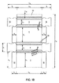
図1Aは、4つの主要矩形パネル3、4、5、6、すなわち、それぞれ幅L1およびL’1を有する2つの第1主要パネル3、5、および、それぞれ幅L2、L’2を有する2つの第2主要パネル4、6のベルト2を含むブランク1を示す。
FIG. 1A shows four main
パネル3、4、5、6のそれぞれは、3本の平行な折り目9、10、11によって幅eを有する矩形切断面を有する2つの部分7、8によって隣接するパネルに接続される。
Each of the
折り目は平型ブランク機、たとえば、スイスの会社BOBSTによって製造された機器によって形成されるので、ブランクの生産中に隣接する折り目がつぶされない。 Since the folds are formed by a flat blank machine, for example equipment manufactured by the Swiss company BOBST, adjacent folds are not crushed during blank production.
そのために、および、幅eが15mmより大きい(20mmまで)場合に、溝を作るためのブレードを囲む付属の発泡体は、ブレードの片側および他側で12mmを超えない寸法を有する。 To that end, and when the width e is greater than 15 mm (up to 20 mm), the attached foam surrounding the blade for making a groove has a dimension not exceeding 12 mm on one side and the other side of the blade.
寸法がそれより小さい場合、発泡体の長さも縮小され、たとえば1cm未満の長さを有するミシン目(図示せず)が、1cm以下ごとに、たとえば、互いに3mm離間された、3mmの長さを有するミシン目が生産される。 If the dimension is smaller, the length of the foam is also reduced, for example perforations (not shown) having a length of less than 1 cm have a length of 3 mm, for example 1 mm or less, separated by 3 mm from each other. A perforation is produced.
それは、溝を形成するための圧力の最小化をできるようにする一方で、引き続き容易かつ適切に折ることができるようにする。 It allows the pressure to form the groove to be minimized while still allowing easy and proper folding.
ベルトはさらに、長さL3を有する接着片12で終わる。
Belt further ends with
パネル3および5のそれぞれは、折り目に対して45°の角度で、パネルに関する接合線14側の下隅15を有する矩形フラップ13の片側および他側で終わる。
Each of the
フラップは、長さl2および幅l3を有する。 The flap has a length l 2 and a width l 3 .
パネル4および6のそれぞれは、それ自身が、折り目17によってパネルに接続されるフラップ16を含み、フラップはチューリップ状形状、および幅l1、および高さl4を有するので、箱が閉鎖されているとき、箱の底面および上面は箱の開放上面に関して実質的に一致し、折り目17側のチューリップ状形状部材の隅は、ファセット18、19を有し、切断面7および8の一部分の端部20、21と協働および/または一致することが可能である。
Each of the
パネルおよび切断面の一部分は、パネル3、5については高さまたは長さL5、パネル4、6については長さL7、および切断面7、8については長さL6をさらに有する。
A portion of the panel and cut surface further has a height or length L 5 for panels 3 , 5 , a length L 7 for
図1Aを参照して述べられる実施形態において、カテゴリーEの段ボール紙(微小な溝の厚み<2mm)について、寸法は、(決して限定しない方法で)たとえば、下記の通りである。 In the embodiment described with reference to FIG. 1A, for category E corrugated paper (minor groove thickness <2 mm), the dimensions are as follows (in no way limiting):
L1 =150mm e =15mm
L’1=151mm l1=88mm
L2 =51mm l2=100mm
L’2=50mm l3=44mm
L3 =25mm l4=92mm
L4 =554mm
L5 =L6=L7=248mm
L8 =432mm
L 1 = 150 mm e = 15 mm
L ′ 1 = 151 mm l 1 = 88 mm
L 2 = 51 mm l 2 = 100 mm
L ′ 2 = 50 mm l 3 = 44 mm
L 3 = 25 mm l 4 = 92 mm
L 4 = 554mm
L 5 = L 6 = L 7 = 248 mm
L 8 = 432 mm
上記において:
L1およびL5はパネル3の幅および長さであり、
L2およびL7はパネル4の幅および長さであり、
L’1およびL5はパネル5の幅および長さであり、
L’2およびL7はパネル6の幅および長さであり、
L3は片12の幅であり、L4はブランクの全長であり、ならびにL8は全幅であり、
eは切断面の一部分の幅であり、L6は面の長さであり、
l1およびl4はフラップ16の長さおよび幅であり、ならびにl2およびl3はフラップ13長さおよび幅である。
In the above:
L 1 and L 5 are the width and length of the
L 2 and L 7 are the width and length of the panel 4,
L ′ 1 and L 5 are the width and length of the
L ′ 2 and L 7 are the width and length of the
L 3 is the width of the
e is the width of a part of the cut surface, L 6 is the length of the surface,
l 1 and l 4 are the length and width of the
以降の本明細書では、同じ要素または類似の要素を指示するために、同じ参照番号が用いられる。 In the following specification, the same reference numbers are used to indicate the same or similar elements.
図1Bは、同様に微小な溝を有する別の実施形態を示し、この例における切断面22の一部分は、数が5つであり、幅がより狭く、たとえば、e=7mmである。
FIG. 1B shows another embodiment that also has micro-grooves, where a portion of the
その他の値は、たとえば:
L1 =146mm e =7mm
L2 =44mm l1=88mm
L’2=43mm l2=100mm
L3 =25mm l3=44mm
L4 =552mm l4=92mm
L5 =L6=L7=248mm
L8 =432mm
Other values are for example:
L 1 = 146 mm e = 7 mm
L 2 = 44 mm l 1 = 88 mm
L ′ 2 = 43 mm l 2 = 100 mm
L 3 = 25 mm l 3 = 44 mm
L 4 = 552 mm l 4 = 92 mm
L 5 = L 6 = L 7 = 248 mm
L 8 = 432 mm
ゆえに、有利なことに:
L1=L’1またはL1<L’1、たとえば、1から2mm。
L2=L’2またはL2<L’2、たとえば、1から2mm。
Hence, advantageously:
L 1 = L ′ 1 or L 1 <L ′ 1 , for example 1 to 2 mm.
L 2 = L ′ 2 or L 2 <L ′ 2 , for example 1 to 2 mm.
L5≠L6、たとえば、L5=248mm、L7=246mm、およびL6=L7またはL6≠L7=245mmを有することも可能である。 It is also possible to have L 5 ≠ L 6 , for example L 5 = 248 mm, L 7 = 246 mm, and L 6 = L 7 or L 6 ≠ L 7 = 245 mm.
図2Aは、本発明に係るブランク24および25のセット23の別の実施形態を示す。
FIG. 2A shows another embodiment of a set 23 of
ブランク24は、下部トレイを形成することが可能である。それは4つの主要パネル27、28、29、30を備えるベルト26を含み、中央矩形パネル29は、2つの切断隅31、32によってその2つの隣接する台形状パネル28、30から分離され、各切断隅は、互いにおよび折り目34によって、隣接するパネルに接続される同一の矩形面33の3つの部分によって形成される。側面を有する矩形パネル27、および矩形接着片35も設けられる。
The blank 24 can form a lower tray. It includes a belt 26 with four main panels 27, 28, 29, 30 and the central rectangular panel 29 is separated from its two adjacent trapezoidal panels 28, 30 by two cutting
各主要パネル28、30はフラップ36、36’ の片側で終わり、そのフラップ36、36’は、パネル29の横中央軸に関して互いに対称であり、実質的に直線である一面37および45°未満の角度を有する切断隅を有する他面38を含む。 Each main panel 28, 30 ends on one side of a flap 36, 36 ', which flap 36, 36' is symmetrical with respect to the transverse central axis of the panel 29 and has a substantially straight side 37 and less than 45 °. It includes an other side 38 having a cut corner with an angle.
箱の形成中に面33の端部と協働するために、パネル27は実質的に矩形のフラップ39を含み、パネル29はパネル29に関する接合線41側で切断された下隅を持つパネル40を含む。 In order to cooperate with the end of the surface 33 during the formation of the box, the panel 27 includes a substantially rectangular flap 39 and the panel 29 includes a panel 40 having a lower corner cut at the joining line 41 side with respect to the panel 29. Including.
ブランク25は、箱のカバーを形成することが可能である。それは、それ自身が、4つの主要パネル43、44、45、46を備えるベルト42を、平行なかたちで含み、矩形中央パネル45は、互いに、および/または、折り目50によって隣接するパネルに接続される、3つの同一の矩形面部分49によって形成される2つの切断隅47、48によって、同様に矩形であるその2つの隣接するパネル44、46から分離される。
The blank 25 can form a box cover. It itself comprises a belt 42 with four
矩形パネル43および接着片51は、パネルの連続物の片側および他側に設けられる。
The rectangular panel 43 and the
第1のブランク24と同一の方法で、該ブランクの方向に関して対称である、フラップ36、36’、39、および40を持つフラップ52、52’、53、および、54が設けられる。 In the same manner as the first blank 24, flaps 52, 52 ', 53, and 54 are provided having flaps 36, 36', 39, and 40 that are symmetrical with respect to the direction of the blank.
図2Bは、トレイ56およびカバー57を含む、図2Aのブランク24および25から生産される箱55の斜視図である。
FIG. 2B is a perspective view of a box 55 produced from the
図2Cは、箱のカバーの領域58および箱の底面の領域59における箱の断面である。 FIG. 2C is a cross section of the box in the box cover area 58 and the box bottom area 59.
例として、寸法の値は下記の通りである(単位 mm):(図2Aおよび2C参照)
L11 =163 l11=190
L’11=164 l21=94
L21 =135 e1 =16
L31 =195 l12=190
L41 =778 l22=93
L51 =82 e2 =15
L61 =176 L52=276
L71 =25 L62=369
L12 =161 L72=30
L’12=159
L22 =134
L32 =193
L42 =767
As an example, the dimension values are as follows (unit: mm): (see FIGS. 2A and 2C)
L 11 = 163 l 11 = 190
L ′ 11 = 164 l 21 = 94
L 21 = 135 e 1 = 16
L 31 = 195 l 12 = 190
L 41 = 778 l 22 = 93
L 51 = 82 e 2 = 15
L 61 = 176 L 52 = 276
L 71 = 25 L 62 = 369
L 12 = 161 L 72 = 30
L ′ 12 = 159
L 22 = 134
L 32 = 193
L 42 = 767
上記において:
L11、L’11、L21、L31は、パネル28、30、29、27の長さであり、
L41は、ブランク23の全長であり、L61は、ブランクの全幅であり、
L51は、パネル27の高さ(または幅)であり、L71は片35の幅であり、l11およびl21は、フラップ40の長さおよび幅であり、e1は、切断面33の一部分の幅である。
In the above:
L 11 , L ′ 11 , L 21 , L 31 are the lengths of the panels 28, 30, 29, 27,
L 41 is the full length of the blank 23, L 61 is the full width of the blank,
L 51 is the height (or width) of the panel 27, L 71 is the width of the
「2」と見出しの付いた参照符号(L12、L’12、等)は、ブランク24のそれらに対応するブランク25のパネルおよび/またはフラップの寸法に対応する。 Reference numerals (L 12 , L ′ 12 , etc.) headed “2” correspond to the panel and / or flap dimensions of the blank 25 corresponding to those of the blank 24.
図3Aは、図2Aから2Cを参照して述べられるタイプの、本発明の別の実施形態を示す。 FIG. 3A shows another embodiment of the present invention of the type described with reference to FIGS. 2A to 2C.
この例において、ブランク61および62は、それぞれが面65、66、67、および68、69、70の3つの部分を備える切断隅63、64、すなわち、第2の幅h2を有する部分66によって分離された第1の幅h1を有する2つの部分65、67、ならびに、第2の幅h’2を有する部分69によって分離された第1の幅h’1を有する2つの部分68および70であって、たとえば、h1=7mm、h2=21mm、ならびにh’1=6mmおよびh’2=20mmを有するもの、を含む。
In this example, the
図3Bは、図3Aのブランク、すなわち、トレイ72用のブランク61、ならびに、2つの側面75および76に3つのファセットを有する切断面74と、いかなるファセットも有さない箱の他隅77とを持つカバー73を作るためのブランク62で得られた箱71の斜視図である。
FIG. 3B shows the blank of FIG. 3A, namely the blank 61 for the
図4および5は、本発明に係る箱の切断隅の2つの実施形態を示す。 4 and 5 show two embodiments of the cut corners of the box according to the invention.
図4は、切断隅81を形成する、切断面の2つの部分79および80を備える箱の角度78を示し、部分79は、たとえば3mmと8mmとの間、たとえば5mmの第1の幅l1を有し、切断面の第2の部分80は、幅e1、たとえば10mmと20mmとの間、たとえば15mmより大きい幅l2を有する。
FIG. 4 shows an
図5は箱の角度82の第2の実施形態を示し、今回は、切断隅86を形成するために3つの異なる幅を有する切断面の3つの部分83、84、85を備え、切断面の部分83は第1の幅l’1、たとえば2mmと5mmとの間、たとえば3mmを有し、切断面第2の部分84は幅l’2、たとえば5mmを有し、切断面の第3の部分85は幅l’3、たとえば12と20mmとの間、たとえば17mmを有する。
FIG. 5 shows a second embodiment of the
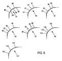
図6は、ファセットを有する、本発明に係る箱に用いることができる、切断隅のその他の例を示す。 FIG. 6 shows another example of a cut corner that can be used in a box according to the invention with facets.
図6は、具体的には、同じ高さの垂直な折り目89によって、互いから及び隣接するパネルに関して分離する、切断面の3つの同一の矩形部分88を備える切断隅87の第1の実施形態を示す。
FIG. 6 specifically shows a first embodiment of a cutting
切断隅のその他の実施形態もここに図示されていて、すなわち:
切断面の4つの同一の垂直部分91を持つ切断隅90、切断面の5つの同一部分93を持つ隅92、切断面の6つの同一部分95を持つ隅94、切断面の7つの部分98を持つ隅97、切断面の8つの部分100を持つ隅99、および、同じ高さを有する切断面の9つの矩形部分102を持つ隅101であって、結果として、その部分は全て、折り目、またはその折ることをできるようにするために設けられる折り線によって分離される。
Other embodiments of cut corners are also illustrated here:
A cutting
このため、4つから5つより多くの切断面から、箱の一般的な寸法を考慮に入れて、その折ることを最適化できるようにするように、溝または折り線または折り目は、たとえば折り目の全長にわたって短距離でプレカットされて、その折ることを容易にする。 For this reason, the grooves or fold lines or creases are, for example, creased so that the fold can be optimized from 4 to more than 5 cut planes taking into account the general dimensions of the box. Is pre-cut at short distances over the entire length of the to facilitate its folding.
図7は、上述の実施形態のうちの1つに係る、箱(図示せず)用形成装置103を模式的および部分的に示す。
FIG. 7 schematically and partially shows a box (not shown) forming
その装置は、特に、かつ、より具体的には、たとえば、結果としてそのまわりに箱を形成することができるマンドレルの四隅で、丸みを帯びたアングル105によって構成されるマンドレル104を含む。
The apparatus includes a
丸みを帯びたアングルは、45°で丸みを帯びている。 The rounded angle is rounded at 45 °.
それらは、図8Aおよび8Bでも、より明瞭に図示されている管状要素によって形成される。 They are formed by tubular elements which are more clearly illustrated in FIGS. 8A and 8B.
それらの管状要素は、たとえばアングル部材の形で、そのまわりで本発明に係る箱の切断隅を折ることをもたらしうる、円筒形の外面を有する。 The tubular elements have a cylindrical outer surface which can result in folding the cut corners of the box according to the invention around it, for example in the form of an angle member.
そのために、たとえば、マンドレルの下方にもたらされるブランクは、マンドレル104のアングル部材の丸みを帯びた外縁108と協働するように構成され、結果として相補的形状であるアングル部材107を含む押板106によって押圧される。マンドレルの上部に位置する押し/押圧手段109および110は、さらに、それ自体公知の方法で動作するために設けられる。
To that end, for example, the blank provided below the mandrel is configured to cooperate with the rounded
それらの押し/押圧手段109および110は、類似の方法で、マンドレル104のアングル部材105の外側円筒面108(1/4円筒部)と協働して、円筒部分の形で外表面113、114を備えるアングルピース111、112を含む。
The pushing / pressing
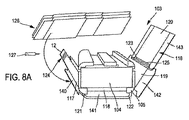
図8Aおよび8Bは、本発明に係る装置の動作、および、結果としてより詳細に説明される形成方法を、より良く理解できるようにするその他の要素を示す。 FIGS. 8A and 8B illustrate other elements that allow a better understanding of the operation of the apparatus according to the present invention and the resulting formation method described in more detail.
装置103は、上述のように切断隅121、122、123、124によって分離された少なくとも4つの主要矩形パネル117、118、119、120を含むベルトを含む、たとえば微小な溝を持つ、段ボール紙シートのブランク116から形成するために構成され、切断隅は結果として、折り目125によって互いに接続される切断面の部分によって形成される。
The
装置103は、図示されたブランクピッキングアセンブリ126、公知の方法で、たとえば高圧で射出される「ホットメルト」接着剤として公知の接着剤を用いて、それ自体が片および/またはフラップ上の所望の場所に接着するための接着手段127を含む。
The
見て取れるように、マンドレル104は、結果として切断隅121、122、123、124と協働することが可能な丸みを帯びたアングル108を含む縁105を含む。
As can be seen, the
上記の巻き付け手段は、マンドレルのまわりにブランクを巻き付け、箱のベルト、押圧手段106、109、および、110を形成し、引き続き丸みを帯びた縁およびフラップでマンドレルのまわりに切断隅を折ることができるようにする。 The above wrapping means can wrap the blank around the mandrel to form a box belt, pressing means 106, 109, and 110, and subsequently fold the cutting corners around the mandrel with rounded edges and flaps. It can be so.
明瞭に示され、それらの折り目の一部分のプレカット部分によって任意に補助された折り目を考慮に入れて、箱がマンドレルのまわりで形成されるとき、折ることは、遊びの発生を正確に取り込むように行われる。 Taking into account the folds that are clearly shown and optionally assisted by precut portions of those fold portions, when the box is formed around the mandrel, folding will accurately capture the occurrence of play. Done.
それは、残りのパネルの障害をさらに考慮に入れて、(あらかじめ、非常に正確に下縁に配置された)ブランクの中央パネルのセルフセンタリングをできるようにする押板106、および、それら自身がきわめて容易な方法で折ることを形成する際に補助することができるピース109および110の両方によってもたらされるガイド動作の結果としてできるようになる。
It further takes into account the remaining panel obstacles, the
図8Bは、切断隅が排出される直前に押板106を取り除いた後に得られる箱128を示す。
FIG. 8B shows the
ピース109および110は、引き続き上方(矢印129)へ移動して、たとえば、その後矢印130の方向に排出される箱の内側に位置するアクチュエータによって、それ自体公知の方法で押し戻される箱を解放できるようにする。
本発明に係る箱を形成する装置の動作は、ここで、図1A、8A、および8Bを参照して、より詳細に説明される。 The operation of the apparatus for forming a box according to the present invention will now be described in more detail with reference to FIGS. 1A, 8A and 8B.
段ボール紙シートのブランクを元にして、特に、かつ、より具体的には、材料の所与の脆弱性およびそれを折ることの所与の困難さを含む微小な溝で、そのブランクは、吸着カップシステムによって、(垂直または傾斜面に位置する)ブランクを取るための従来技術によってピッキングされる。 Based on a corrugated paper sheet blank, in particular, and more specifically, with a small groove containing a given vulnerability of material and a given difficulty of folding it, the blank is adsorbed By the cup system, picking is performed according to the prior art for taking blanks (located in a vertical or inclined plane).
その後、梱包材は、たとえばコンベアベルト(図示せず)を介してマンドレルの下方へ移される。 Thereafter, the packing material is moved below the mandrel via, for example, a conveyor belt (not shown).
マンドレルの真下に配置されたブランクで、引き続き、切断隅がマンドレルの側面アングル部材105に整列して移動するように、押板106によって持ち上げられて事前押圧される。
A blank placed directly under the mandrel is subsequently lifted and pre-pressed by the
押板は引き続き前進して、ブランクが配置につき、切断隅は加圧に従って屈曲し、側面パネル119および117自身は、切断隅およびその切断面の一部分が、アングル部材105に対して完全につぶされずに、適切に折ることができるようになるために、横方向に維持され、それは、上記に示されるような、そのファセット状外観から恩恵を受けることなく、切断隅が完全に丸みを帯びる効果を有する。
The push plate continues to advance, the blank is placed, the cutting corners bend according to the pressure, and the
ブランクの残りの部分は、引き続き、切断隅123、124がマンドレルの上方から移動して、アングル部材105と接触するまで、漸進的にマンドレルのまわりに巻き付けられ、そして押圧システムは、下部の切断隅に関しては、マンドレルの丸みを帯びた縁上に切断隅を形成できるようにすることにより、梱包材の切断面の一部分によって形成される、ファセットを近接して折ることができるようにする。
The remaining portion of the blank continues to wrap around the mandrel progressively until the cutting
引き続き、上部パネル120は明確に閉鎖され、端部片の配置は、押圧によってパネル120の端部で行われる。
Subsequently, the
引き続き、および/または同時に、箱の底面の形成が意図され、かつブランクの断面に対して同一の形状であるフラップ140、141、142、および、143は、切断隅を含めて、いったん折られたら、マンドレルの端部に対して押圧され、その間、接着手段127による初期接着が動作中に行われる。 Subsequently, and / or simultaneously, flaps 140, 141, 142, and 143 that are intended to form the bottom of the box and that have the same shape relative to the blank cross-section once folded, including the cut corners. The mandrel is pressed against the end of the mandrel, during which initial bonding by the bonding means 127 is performed during operation.
箱は、引き続き、図8Bを参照して矢印130にしたがって排出される。
The box is subsequently ejected according to
自明であり、さらに上記からの結果として、本発明は、より詳細に説明された実施形態に限定されない。むしろ、全ての変形例、特に、より詳細に説明されたように、下方からではなく上方からの、マンドレル上のブランクへのアクセス場所を含むものを含む。 Obviously and as a result of the above, the present invention is not limited to the embodiments described in more detail. Rather, all variations are included, particularly those including access locations to the blank on the mandrel from above rather than from below, as described in more detail.
Claims (24)
箱は、少なくとも4つの主要矩形パネルを含み、少なくとも部分的に箱の底面および/または上面を形成することが可能な少なくとも一連のフラップを備えるベルトを備え、
主要側面パネルのうちの少なくとも2つが中間パネルによって主要中央パネルに接続され、フラップを有さない切断隅を形成し、少なくとも2つの切断隅は折り目によって、互いにまたは隣接する主要パネルに接続される少なくとも2つの切断面の矩形部分によって形成されること、を含み、
切断面の部分が、3mmから20mmの間の幅を有すること、および少なくとも2つの対向する主要パネルが、異なる幅を有すること、
を特徴とする箱。 A box (55, 71) of corrugated paper sheet material having a polygonal cross section,
The box comprises a belt comprising at least a series of flaps including at least four main rectangular panels and capable of at least partially forming the bottom and / or top of the box;
At least two of the main side panels are connected to the main central panel by an intermediate panel to form a cut corner without a flap, and at least two cut corners are connected to each other or to adjacent main panels by folds Formed by a rectangular portion of two cut surfaces,
The section of the cut surface has a width between 3 mm and 20 mm, and at least two opposing main panels have different widths;
A box characterized by.
各主要パネルが少なくとも1つのフラップを備え、
各切断隅が少なくとも2つの切断面の部分を含むこと、を特徴とする上記請求項のうちのいずれか1項に記載の箱。 A box is formed from at least one blank, each comprising a series of at least four main panels, connected to its adjacent panels via intermediate panels that form cut corners;
Each main panel comprises at least one flap,
A box according to any one of the preceding claims, wherein each cut corner includes at least two cut surface portions.
ブランクまたは各ブランクは、少なくとも4つの主要矩形パネルを含み、少なくとも部分的に箱の底面および/または上面を形成することが可能な少なくとも一連のフラップを備えるベルトを備え、
主要側面パネルのうちの少なくとも2つが中間パネルによって主要中央パネルに接続され、フラップを有さない切断隅を形成し、各中間パネルが折り目によって、互いにまたは隣接する主要パネルに接続される少なくとも2つの切断面の矩形部分によって形成されるものを含み、
切断面の部分が3mmから20mmの間の幅を有すること、および少なくとも2つの対向する主要パネルが異なる幅を有すること、
を特徴とするブランクまたは各ブランク。 A blank or a set of two blanks produced from corrugated paper sheet material and intended to form a box with a polygonal cross section,
The blank or each blank comprises at least four main rectangular panels and comprises a belt comprising at least a series of flaps capable of forming at least partly the bottom and / or top of the box;
At least two of the main side panels are connected to the main central panel by intermediate panels to form cut corners without flaps, and each intermediate panel is connected to each other or to adjacent main panels by folds Including those formed by the rectangular portion of the cut surface,
The section of the cut surface has a width between 3 mm and 20 mm, and at least two opposing main panels have different widths;
Characterized by blanks or each blank.
フラップを有さない切断隅を形成する中間パネルによって主要中央パネルに接続される少なくとも2つの主要パネルで、各切断隅が、折り目によって互いに接続される少なくとも2つの切断面の矩形部分によって形成されるものであって、
ブランクをピッキングするためのアセンブリを含み、
切断面の部分が3mmから20mmの間の幅を有し、少なくとも2つの対向する主要パネルが異なる幅を有し、前記装置がマンドレルへの移転中にブランクを接着するための手段を含み、
マンドレルが、切断隅と協働することが可能な丸みを帯びたアングルを含む少なくとも2つの縁、箱のベルトを形成するために、マンドレルのまわりにブランクを巻き付けるための手段、接着剤での接着によって箱の底面を形成するために、丸みを帯びた縁上の切断隅、およびマンドレルのまわりのフラップを折るために構成された押圧手段を含むこと、
を特徴とする装置。 Apparatus for forming a box from at least one blank of corrugated paper sheet comprising a belt comprising at least one side having a series of flaps including at least four primary rectangular panels and capable of at least partially forming the bottom of the box Because
With at least two main panels connected to the main central panel by an intermediate panel forming a cutting corner without a flap, each cutting corner is formed by a rectangular portion of at least two cutting surfaces connected to each other by a crease And
Including an assembly for picking blanks,
The section of the cutting surface has a width between 3 mm and 20 mm, the at least two opposing main panels have different widths, the device comprising means for bonding the blank during transfer to the mandrel;
At least two edges including a rounded angle where the mandrel can co-operate with the cutting corner, means for winding the blank around the mandrel to form a box belt, adhesive bonding Including a cutting corner on the rounded edge and a pressing means configured to fold the flap around the mandrel to form the bottom surface of the box by
A device characterized by.
フラップを有さない切断隅を形成する中間パネルによって主要中央パネルに接続される少なくとも2つの主要パネルで、各切断隅が、折り目によって互いに接続される切断面の矩形部分を形成する少なくとも2つの中間パネルによって形成されることを特徴とし、
切断面の部分が3mmから20mmの間の幅を有し、少なくとも2つの対向する主要パネルが異なる幅を有し、
ブランクがピッキングされた後で、
ブランクがマンドレルへの移転中に接着され、
マンドレルが、切断隅と協働することが可能な丸みを帯びたアングルを含む少なくとも2つの縁を含み、
箱のベルトを形成するために、ブランクがマンドレルのまわりに巻き付けられ、
箱の切断隅および底面を形成するために、中間パネルが丸みを帯びた縁に押圧され、フラップがマンドレルのまわりに押圧されることを、
特徴とする、方法。 A method of forming a box from at least one blank of corrugated paper sheet comprising a belt comprising at least one side having a series of flaps including at least four primary rectangular panels and capable of forming at least partially the bottom of the box Because
At least two main panels connected to the main central panel by an intermediate panel forming a cut corner without a flap, each cut corner forming at least two intermediate sections of a cut surface connected to each other by a crease Characterized by being formed by panels,
The section of the cutting surface has a width between 3 mm and 20 mm, and at least two opposing main panels have different widths;
After the blank is picked,
The blank is glued during the transfer to the mandrel,
The mandrel includes at least two edges including a rounded angle capable of cooperating with the cutting corner;
A blank is wrapped around the mandrel to form a box belt,
That the intermediate panel is pressed against the rounded edges and the flaps are pressed around the mandrel to form the cut corners and bottom of the box,
Features, a method.
Applications Claiming Priority (3)
| Application Number | Priority Date | Filing Date | Title |
|---|---|---|---|
| FR1201748A FR2992294B1 (en) | 2012-06-20 | 2012-06-20 | CARDBOARD SHEET, FLAN OR FLAN ASSEMBLY, METHOD AND DEVICE FOR FORMING SUCH A BOX |
| FR12/01748 | 2012-06-20 | ||
| PCT/FR2013/051412 WO2013190226A1 (en) | 2012-06-20 | 2013-06-17 | Box made of a cardboard sheet material, blank or blank assembly, and method and device for forming such a box |
Publications (2)
| Publication Number | Publication Date |
|---|---|
| JP2015523938A true JP2015523938A (en) | 2015-08-20 |
| JP2015523938A5 JP2015523938A5 (en) | 2016-06-16 |
Family
ID=46826581
Family Applications (1)
| Application Number | Title | Priority Date | Filing Date |
|---|---|---|---|
| JP2015517826A Pending JP2015523938A (en) | 2012-06-20 | 2013-06-17 | Boxes made of cardboard sheet material, blanks or blank assemblies, and methods and apparatus for forming such boxes |
Country Status (9)
| Country | Link |
|---|---|
| US (1) | US20150175293A1 (en) |
| EP (1) | EP2864210B1 (en) |
| JP (1) | JP2015523938A (en) |
| DK (1) | DK2864210T3 (en) |
| ES (1) | ES2588055T3 (en) |
| FR (1) | FR2992294B1 (en) |
| PL (1) | PL2864210T3 (en) |
| WO (1) | WO2013190226A1 (en) |
| ZA (1) | ZA201408800B (en) |
Families Citing this family (4)
| Publication number | Priority date | Publication date | Assignee | Title |
|---|---|---|---|---|
| US10987889B2 (en) * | 2015-09-21 | 2021-04-27 | Westrock Shared Services, Llc | Methods and machine for forming a shipping container with an article retaining web |
| US20190315511A1 (en) * | 2018-04-13 | 2019-10-17 | Georgia-Pacific Corrugated Llc | Container with rounded corner or corners |
| IT201800006419A1 (en) * | 2018-06-18 | 2019-12-18 | APPARATUS AND METHOD FOR FORMING BOXES WITH CURVED CORNERS FROM A DIE CUT SHEET | |
| CN114379144B (en) * | 2021-11-30 | 2023-07-14 | 石家庄市纵伟泰纸制品有限公司 | Carton cutting device and application method thereof |
Citations (13)
| Publication number | Priority date | Publication date | Assignee | Title |
|---|---|---|---|---|
| JPS54103188A (en) * | 1978-01-31 | 1979-08-14 | Dainippon Printing Co Ltd | Method of molding carton that is flatly wound |
| JPS60167720U (en) * | 1984-04-12 | 1985-11-07 | 積水化成品工業株式会社 | assembly box |
| US5044550A (en) * | 1989-08-22 | 1991-09-03 | Tobacco Research And Development Institute Limited | Flip-top cartons |
| JPH05193648A (en) * | 1992-01-10 | 1993-08-03 | Fujikou Kk | Container for packing |
| JP3006889U (en) * | 1994-07-19 | 1995-01-31 | 株式会社パックス | Square paper packaging container |
| JPH08217060A (en) * | 1995-02-17 | 1996-08-27 | Toppan Printing Co Ltd | Re-sealable paper box |
| JPH0940050A (en) * | 1995-05-31 | 1997-02-10 | Focke & Co Gmbh & Co | Pack with hinged lid for cigarette |
| US6003759A (en) * | 1997-05-20 | 1999-12-21 | Cd Cartondruck Gmbh | Folding box |
| JP2005111991A (en) * | 2003-10-08 | 2005-04-28 | G D Spa | Unit and method for bending flat blank to form firm package |
| JP2009533286A (en) * | 2006-04-12 | 2009-09-17 | オトール・ソシエテ・アノニム | Display case with slidable cover |
| EP2436613A1 (en) * | 2010-09-30 | 2012-04-04 | A&R Carton Bremen GmbH | Folding box |
| WO2012042275A1 (en) * | 2010-09-30 | 2012-04-05 | Concept Packaging Services Limited | Improvements in and relating to cartons |
| JP2012140174A (en) * | 2011-01-06 | 2012-07-26 | Rengo Co Ltd | Connected cardboard box |
Family Cites Families (12)
| Publication number | Priority date | Publication date | Assignee | Title |
|---|---|---|---|---|
| US3866523A (en) * | 1973-05-30 | 1975-02-18 | Lancaster Research And Dev Cor | Method and apparatus for forming bulk containers from articulatable composite panels |
| US4955531A (en) * | 1989-02-21 | 1990-09-11 | Herman Graboyes | Blank for use in forming a container having a rounded edge |
| FR2665137B1 (en) * | 1990-07-24 | 1994-07-01 | Otor Sa | CRATES IN A SHEET MATERIAL, BLANKS AND MACHINE FOR THE PRODUCTION OF SUCH CRATES. |
| DE4341129A1 (en) * | 1993-12-02 | 1995-06-08 | Kettner Verpackungsmaschf | Hollow body made from single sheet |
| WO1996016789A1 (en) * | 1994-11-30 | 1996-06-06 | Tetra Laval Holdings & Finance S.A. | Adjustable mandrel |
| FR2743779B1 (en) * | 1996-01-22 | 1998-04-17 | Otor Sa | SET OF CUTTINGS FOR A PACKING CASE FORMING A DISPLAY BOX AND A BOX OBTAINED WITH SUCH AN ASSEMBLY |
| US5924627A (en) * | 1997-08-07 | 1999-07-20 | Philip Morris Incorporated | Packaging blank and container made therefrom |
| FR2795390B1 (en) * | 1999-06-23 | 2001-12-07 | Otor Sa | BOX IN CARDBOARD AND SET OF CUT TO OBTAIN SUCH A BOX |
| US7090115B2 (en) * | 2003-03-26 | 2006-08-15 | Leon William Pierce | Container for bagged beverages |
| US20050199692A1 (en) * | 2004-03-05 | 2005-09-15 | Nelson Daniel J. | Blank capable of forming a container having rounded corners |
| JP2008532875A (en) * | 2005-03-21 | 2008-08-21 | ミードウエストヴェイコ・パッケージング・システムズ・エルエルシー | Carton for housing multiple tapered containers |
| US7935041B2 (en) * | 2008-08-25 | 2011-05-03 | Smurfit-Stone Container Enterprises, Inc. | Container with inner reinforcement and method and system of manufacturing |
-
2012
- 2012-06-20 FR FR1201748A patent/FR2992294B1/en not_active Expired - Fee Related
-
2013
- 2013-06-17 PL PL13737329.6T patent/PL2864210T3/en unknown
- 2013-06-17 DK DK13737329.6T patent/DK2864210T3/en active
- 2013-06-17 JP JP2015517826A patent/JP2015523938A/en active Pending
- 2013-06-17 WO PCT/FR2013/051412 patent/WO2013190226A1/en active Application Filing
- 2013-06-17 ES ES13737329.6T patent/ES2588055T3/en active Active
- 2013-06-17 US US14/409,744 patent/US20150175293A1/en not_active Abandoned
- 2013-06-17 EP EP13737329.6A patent/EP2864210B1/en active Active
-
2014
- 2014-12-01 ZA ZA2014/08800A patent/ZA201408800B/en unknown
Patent Citations (13)
| Publication number | Priority date | Publication date | Assignee | Title |
|---|---|---|---|---|
| JPS54103188A (en) * | 1978-01-31 | 1979-08-14 | Dainippon Printing Co Ltd | Method of molding carton that is flatly wound |
| JPS60167720U (en) * | 1984-04-12 | 1985-11-07 | 積水化成品工業株式会社 | assembly box |
| US5044550A (en) * | 1989-08-22 | 1991-09-03 | Tobacco Research And Development Institute Limited | Flip-top cartons |
| JPH05193648A (en) * | 1992-01-10 | 1993-08-03 | Fujikou Kk | Container for packing |
| JP3006889U (en) * | 1994-07-19 | 1995-01-31 | 株式会社パックス | Square paper packaging container |
| JPH08217060A (en) * | 1995-02-17 | 1996-08-27 | Toppan Printing Co Ltd | Re-sealable paper box |
| JPH0940050A (en) * | 1995-05-31 | 1997-02-10 | Focke & Co Gmbh & Co | Pack with hinged lid for cigarette |
| US6003759A (en) * | 1997-05-20 | 1999-12-21 | Cd Cartondruck Gmbh | Folding box |
| JP2005111991A (en) * | 2003-10-08 | 2005-04-28 | G D Spa | Unit and method for bending flat blank to form firm package |
| JP2009533286A (en) * | 2006-04-12 | 2009-09-17 | オトール・ソシエテ・アノニム | Display case with slidable cover |
| EP2436613A1 (en) * | 2010-09-30 | 2012-04-04 | A&R Carton Bremen GmbH | Folding box |
| WO2012042275A1 (en) * | 2010-09-30 | 2012-04-05 | Concept Packaging Services Limited | Improvements in and relating to cartons |
| JP2012140174A (en) * | 2011-01-06 | 2012-07-26 | Rengo Co Ltd | Connected cardboard box |
Also Published As
| Publication number | Publication date |
|---|---|
| EP2864210B1 (en) | 2016-05-25 |
| US20150175293A1 (en) | 2015-06-25 |
| ZA201408800B (en) | 2016-10-26 |
| ES2588055T3 (en) | 2016-10-28 |
| WO2013190226A1 (en) | 2013-12-27 |
| FR2992294A1 (en) | 2013-12-27 |
| PL2864210T3 (en) | 2016-11-30 |
| EP2864210A1 (en) | 2015-04-29 |
| FR2992294B1 (en) | 2015-07-31 |
| DK2864210T3 (en) | 2016-08-29 |
Similar Documents
| Publication | Publication Date | Title |
|---|---|---|
| US7516599B2 (en) | Methods and apparatus for manufacture of a reclosable plastic carton | |
| US11325740B2 (en) | Straight consistent body scores on plastic corrugated boxes and a process for making same | |
| CA2851357C (en) | Plastic corrugated container with improved fold lines and method and apparatus for making same | |
| KR101695513B1 (en) | Fold-resistance reducing mechanism | |
| US10829265B2 (en) | Straight consistent body scores on plastic corrugated boxes and a process for making same | |
| US9796498B2 (en) | Method of making a preassembled display with automatic stackable supports | |
| US11319132B2 (en) | Plastic corrugated container with soft score line | |
| JP6863340B2 (en) | How to assemble the packaging box | |
| US10022943B2 (en) | Package material blank and method of forming the same | |
| JP2015523938A (en) | Boxes made of cardboard sheet material, blanks or blank assemblies, and methods and apparatus for forming such boxes | |
| JP6536342B2 (en) | Box and box blank sheet | |
| US10046882B2 (en) | Reduced-width blank for forming a carton and sheet containing such blanks | |
| JP2015030246A (en) | Method for producing packaging box | |
| US9938039B2 (en) | Box for packing and exhibiting product, and packing device therefor | |
| JP2015523938A5 (en) | ||
| RU2016106991A (en) | CUTTING PREPARATION AND METHOD FOR MANUFACTURING TRANSPORT PACKAGING | |
| US10081470B2 (en) | Reclosable packing case and method of making same | |
| JP7232635B2 (en) | Chamfered box | |
| JP6896959B2 (en) | Box forming material for thin cardboard boxes and sheets for cardboard boxes | |
| JP7072342B2 (en) | Double corrugated cardboard sheet and its manufacturing method | |
| RU2615623C1 (en) | Package for smoking products | |
| JP7360302B2 (en) | Packaging box with polygonal partitions | |
| JP5612951B2 (en) | Packaging box | |
| JP2004262032A (en) | Female creaser die for forming crease | |
| JP7224900B2 (en) | packaging box |
Legal Events
| Date | Code | Title | Description |
|---|---|---|---|
| A521 | Request for written amendment filed |
Free format text: JAPANESE INTERMEDIATE CODE: A523 Effective date: 20160425 |
|
| A621 | Written request for application examination |
Free format text: JAPANESE INTERMEDIATE CODE: A621 Effective date: 20160425 |
|
| A977 | Report on retrieval |
Free format text: JAPANESE INTERMEDIATE CODE: A971007 Effective date: 20161027 |
|
| A131 | Notification of reasons for refusal |
Free format text: JAPANESE INTERMEDIATE CODE: A131 Effective date: 20161101 |
|
| A601 | Written request for extension of time |
Free format text: JAPANESE INTERMEDIATE CODE: A601 Effective date: 20170126 |
|
| A521 | Request for written amendment filed |
Free format text: JAPANESE INTERMEDIATE CODE: A523 Effective date: 20170322 |
|
| A131 | Notification of reasons for refusal |
Free format text: JAPANESE INTERMEDIATE CODE: A131 Effective date: 20170801 |
|
| A601 | Written request for extension of time |
Free format text: JAPANESE INTERMEDIATE CODE: A601 Effective date: 20171019 |
|
| A02 | Decision of refusal |
Free format text: JAPANESE INTERMEDIATE CODE: A02 Effective date: 20180306 |