JP2015523646A - Collision prevention system for ground workers using sensors - Google Patents
Collision prevention system for ground workers using sensors Download PDFInfo
- Publication number
- JP2015523646A JP2015523646A JP2015515173A JP2015515173A JP2015523646A JP 2015523646 A JP2015523646 A JP 2015523646A JP 2015515173 A JP2015515173 A JP 2015515173A JP 2015515173 A JP2015515173 A JP 2015515173A JP 2015523646 A JP2015523646 A JP 2015523646A
- Authority
- JP
- Japan
- Prior art keywords
- radar
- aircraft
- ground
- ground obstacle
- detected
- Prior art date
- Legal status (The legal status is an assumption and is not a legal conclusion. Google has not performed a legal analysis and makes no representation as to the accuracy of the status listed.)
- Pending
Links
Images


Classifications
-
- G—PHYSICS
- G08—SIGNALLING
- G08G—TRAFFIC CONTROL SYSTEMS
- G08G5/00—Traffic control systems for aircraft, e.g. air-traffic control [ATC]
- G08G5/04—Anti-collision systems
-
- G—PHYSICS
- G01—MEASURING; TESTING
- G01S—RADIO DIRECTION-FINDING; RADIO NAVIGATION; DETERMINING DISTANCE OR VELOCITY BY USE OF RADIO WAVES; LOCATING OR PRESENCE-DETECTING BY USE OF THE REFLECTION OR RERADIATION OF RADIO WAVES; ANALOGOUS ARRANGEMENTS USING OTHER WAVES
- G01S13/00—Systems using the reflection or reradiation of radio waves, e.g. radar systems; Analogous systems using reflection or reradiation of waves whose nature or wavelength is irrelevant or unspecified
- G01S13/88—Radar or analogous systems specially adapted for specific applications
- G01S13/93—Radar or analogous systems specially adapted for specific applications for anti-collision purposes
- G01S13/933—Radar or analogous systems specially adapted for specific applications for anti-collision purposes of aircraft or spacecraft
-
- G—PHYSICS
- G01—MEASURING; TESTING
- G01S—RADIO DIRECTION-FINDING; RADIO NAVIGATION; DETERMINING DISTANCE OR VELOCITY BY USE OF RADIO WAVES; LOCATING OR PRESENCE-DETECTING BY USE OF THE REFLECTION OR RERADIATION OF RADIO WAVES; ANALOGOUS ARRANGEMENTS USING OTHER WAVES
- G01S13/00—Systems using the reflection or reradiation of radio waves, e.g. radar systems; Analogous systems using reflection or reradiation of waves whose nature or wavelength is irrelevant or unspecified
- G01S13/88—Radar or analogous systems specially adapted for specific applications
- G01S13/93—Radar or analogous systems specially adapted for specific applications for anti-collision purposes
- G01S13/931—Radar or analogous systems specially adapted for specific applications for anti-collision purposes of land vehicles
-
- G—PHYSICS
- G01—MEASURING; TESTING
- G01S—RADIO DIRECTION-FINDING; RADIO NAVIGATION; DETERMINING DISTANCE OR VELOCITY BY USE OF RADIO WAVES; LOCATING OR PRESENCE-DETECTING BY USE OF THE REFLECTION OR RERADIATION OF RADIO WAVES; ANALOGOUS ARRANGEMENTS USING OTHER WAVES
- G01S7/00—Details of systems according to groups G01S13/00, G01S15/00, G01S17/00
- G01S7/003—Transmission of data between radar, sonar or lidar systems and remote stations
-
- G—PHYSICS
- G01—MEASURING; TESTING
- G01S—RADIO DIRECTION-FINDING; RADIO NAVIGATION; DETERMINING DISTANCE OR VELOCITY BY USE OF RADIO WAVES; LOCATING OR PRESENCE-DETECTING BY USE OF THE REFLECTION OR RERADIATION OF RADIO WAVES; ANALOGOUS ARRANGEMENTS USING OTHER WAVES
- G01S7/00—Details of systems according to groups G01S13/00, G01S15/00, G01S17/00
- G01S7/02—Details of systems according to groups G01S13/00, G01S15/00, G01S17/00 of systems according to group G01S13/00
- G01S7/04—Display arrangements
-
- G—PHYSICS
- G08—SIGNALLING
- G08G—TRAFFIC CONTROL SYSTEMS
- G08G5/00—Traffic control systems for aircraft, e.g. air-traffic control [ATC]
- G08G5/0017—Arrangements for implementing traffic-related aircraft activities, e.g. arrangements for generating, displaying, acquiring or managing traffic information
- G08G5/0021—Arrangements for implementing traffic-related aircraft activities, e.g. arrangements for generating, displaying, acquiring or managing traffic information located in the aircraft
-
- G—PHYSICS
- G08—SIGNALLING
- G08G—TRAFFIC CONTROL SYSTEMS
- G08G5/00—Traffic control systems for aircraft, e.g. air-traffic control [ATC]
- G08G5/06—Traffic control systems for aircraft, e.g. air-traffic control [ATC] for control when on the ground
- G08G5/065—Navigation or guidance aids, e.g. for taxiing or rolling
-
- G—PHYSICS
- G01—MEASURING; TESTING
- G01S—RADIO DIRECTION-FINDING; RADIO NAVIGATION; DETERMINING DISTANCE OR VELOCITY BY USE OF RADIO WAVES; LOCATING OR PRESENCE-DETECTING BY USE OF THE REFLECTION OR RERADIATION OF RADIO WAVES; ANALOGOUS ARRANGEMENTS USING OTHER WAVES
- G01S13/00—Systems using the reflection or reradiation of radio waves, e.g. radar systems; Analogous systems using reflection or reradiation of waves whose nature or wavelength is irrelevant or unspecified
- G01S13/88—Radar or analogous systems specially adapted for specific applications
- G01S13/93—Radar or analogous systems specially adapted for specific applications for anti-collision purposes
- G01S13/933—Radar or analogous systems specially adapted for specific applications for anti-collision purposes of aircraft or spacecraft
- G01S13/934—Radar or analogous systems specially adapted for specific applications for anti-collision purposes of aircraft or spacecraft on airport surfaces, e.g. while taxiing
-
- G—PHYSICS
- G01—MEASURING; TESTING
- G01S—RADIO DIRECTION-FINDING; RADIO NAVIGATION; DETERMINING DISTANCE OR VELOCITY BY USE OF RADIO WAVES; LOCATING OR PRESENCE-DETECTING BY USE OF THE REFLECTION OR RERADIATION OF RADIO WAVES; ANALOGOUS ARRANGEMENTS USING OTHER WAVES
- G01S13/00—Systems using the reflection or reradiation of radio waves, e.g. radar systems; Analogous systems using reflection or reradiation of waves whose nature or wavelength is irrelevant or unspecified
- G01S13/88—Radar or analogous systems specially adapted for specific applications
- G01S13/91—Radar or analogous systems specially adapted for specific applications for traffic control
- G01S2013/916—Airport surface monitoring [ASDE]
-
- G—PHYSICS
- G01—MEASURING; TESTING
- G01S—RADIO DIRECTION-FINDING; RADIO NAVIGATION; DETERMINING DISTANCE OR VELOCITY BY USE OF RADIO WAVES; LOCATING OR PRESENCE-DETECTING BY USE OF THE REFLECTION OR RERADIATION OF RADIO WAVES; ANALOGOUS ARRANGEMENTS USING OTHER WAVES
- G01S7/00—Details of systems according to groups G01S13/00, G01S15/00, G01S17/00
- G01S7/02—Details of systems according to groups G01S13/00, G01S15/00, G01S17/00 of systems according to group G01S13/00
- G01S7/04—Display arrangements
- G01S7/06—Cathode-ray tube displays or other two dimensional or three-dimensional displays
- G01S7/22—Producing cursor lines and indicia by electronic means
Abstract
地上障害物衝突防止システムは、各々がレーダ検出器において地上障害物からの放出された信号の反射に対応するレーダリターン信号を受け取り、地上障害物から反射された受け取られたレーダ信号反射に関連付けられたレーダ情報を送る、複数のレーダセンサモジュールであって、複数のレーダセンサモジュールの各々が、航空機が移動している場合に地上障害物との衝突の危険性がある航空機の表面上に一意的に配置される、複数のレーダセンサモジュールと、レーダセンサモジュールから送られたレーダ情報を受け取り、受け取られたレーダ情報に関連付けられる情報を送るゲートウェイユニットと、搭載機から検出された地上物体までの距離を決定するように構成された処理システムと、航空機アイコンと検出された地上障害物に関連付けられるグラフィカルな地上障害物アイコンとを示す平面図を提示するように構成されるディスプレイとを含む。Ground obstacle collision prevention systems each receive a radar return signal corresponding to the reflection of the emitted signal from the ground obstacle at the radar detector and are associated with the received radar signal reflection reflected from the ground obstacle. Multiple radar sensor modules that transmit radar information, each of the multiple radar sensor modules being unique on the surface of the aircraft where there is a risk of collision with a ground obstacle when the aircraft is moving A plurality of radar sensor modules, a gateway unit that receives radar information sent from the radar sensor module and sends information associated with the received radar information, and a distance from the onboard machine to the detected ground object A processing system configured to determine the aircraft icons and detected ground obstacles. To present a plan view showing the graphical ground obstacle icon attached and a configured display.
Description
本発明は、センサを用いた地上勤務員(グラウンド・クルー)のための衝突防止システムに関する。 The present invention relates to a collision prevention system for a ground crew using a sensor.
[0001]航空機搭乗員や地上で航空機を操作する地上勤務員は、航空機が移動しているときに航空機の一部が他の物体と衝突する可能性を意識することが困難である場合がある。その困難さは、航空機及び/又は牽引車(tow tug)が比較的大きなサイズであるために引き起こされる視界の制限に部分的に起因して、また、他の移動車両など又は誘導路操作や航空機搭乗員によって行われる関連する操作などの、邪魔になる可能性のあるものに起因して生じる。 [0001] Aircraft crew and ground workers who operate an aircraft on the ground may have difficulty in being aware of the possibility that some of the aircraft will collide with other objects when the aircraft is moving. The difficulty is due in part to the limited visibility caused by the relatively large size of the aircraft and / or tow tug, as well as other moving vehicles or taxiway operations and aircraft Caused by things that can get in the way, such as related operations performed by the crew.
[0002]地上にある地上障害物が牽引される航空機の行く手を塞いでいる場合、牽引される航空機の翼端やテールが誤って地上障害物に衝突する可能性がある。地上障害物の例は、格納庫もしくは他の建物、照明ポール、車両、別の航空機、又はフェンスを含むが、これらに限定されない。したがって、当技術分野において、牽引される航空機の地上障害物との不注意な衝突の回数及び/又は重大性を低減する要求がある。 [0002] When a ground obstacle on the ground blocks the hand of the aircraft being towed, the wing tip or tail of the towed aircraft may accidentally collide with the ground obstacle. Examples of ground obstacles include, but are not limited to, hangars or other buildings, lighting poles, vehicles, other aircraft, or fences. Accordingly, there is a need in the art to reduce the number and / or severity of inadvertent collisions of towed aircraft with ground obstacles.
[0003]本発明は、航空機の搭乗員及び/又は地上勤務員のメンバーのための地上障害物衝突防止システムを提供する。例示的な実施例は、各々がレーダ検出器において地上障害物からの放出された信号の反射に対応するレーダリターン信号を受け取り、地上障害物から反射された受け取られたレーダ信号反射に関連付けられたレーダ情報を送る、複数のレーダセンサモジュールであって、複数のレーダセンサモジュールの各々が、航空機が移動している場合に地上障害物との衝突の危険性がある航空機の表面上に一意的に配置される、複数のレーダセンサモジュールと、レーダセンサモジュールから送られたレーダ情報を受け取り、受け取られたレーダ情報に関連付けられる情報を送るゲートウェイユニットと、搭載機(installation aircraft)から検出された地上物体までの距離を決定するように構成された処理システムと、航空機アイコンと検出された地上障害物に関連付けられるグラフィカルな地上障害物アイコンとを示す平面図を提示するように構成されるディスプレイとを含む。提示されるグラフィカルな地上障害物アイコンは、航空機と地上障害物との間の衝突を回避するように航空機を操作することができるように、航空機の近傍にある地上障害物の位置を示す。 [0003] The present invention provides a ground obstacle collision prevention system for aircraft crew and / or ground crew members. Exemplary embodiments each receive a radar return signal corresponding to a reflection of an emitted signal from a ground obstacle at a radar detector and associated with the received radar signal reflection reflected from the ground obstacle. A plurality of radar sensor modules for sending radar information, each of the plurality of radar sensor modules being uniquely on the surface of the aircraft that is at risk of collision with a ground obstacle when the aircraft is moving A plurality of radar sensor modules arranged, a gateway unit that receives radar information sent from the radar sensor module and sends information associated with the received radar information, and a ground object detected from an installation aircraft Processing system configured to determine the distance to the aircraft, aircraft icons and detected ground faults It shows a graphical ground obstacles icons associated with and a display configured to present the plan view. The presented graphical ground obstacle icon indicates the location of a ground obstacle in the vicinity of the aircraft so that the aircraft can be operated to avoid a collision between the aircraft and the ground obstacle.
[0004]本発明の好ましい実施例及び代替的な実施例を以下の図面を参照しながら以下において詳細に説明する。 [0004] Preferred and alternative embodiments of the present invention are described in detail below with reference to the following drawings.
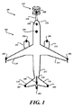
[0012]図1は、搭載機(installation aircraft)102(互換的に、航空機102と呼ばれる)に具体化される例示的な地上障害物衝突防止システム100の実施例の図である。地上障害物衝突防止システム100は、航空機102が航空機搭乗員の制御下で移動され及び/又は地上勤務員によって牽引されている間、地上障害物との衝突の危険性があり得る選択された位置において航空機102の外側に配置されたレーダセンサモジュール104(例えば、レーダエミッタ/検出器デバイス)を含む。
[0012] FIG. 1 is a diagram of an example of an exemplary ground obstacle
[0013]レーダセンサモジュール104はレーダ信号を放出する。地上障害物からのレーダ信号リターンが1つ又は複数のレーダセンサモジュール104によって検出される場合、検出された地上障害物の位置について決定がなされる。航空機搭乗員の制御下にある間の航空機102の移動中、及び/又は、地上勤務員による航空機102の牽引中、提示される平面図は、検出された地上障害物の存在及び相対的位置を示す。
[0013] The
[0014]例示的な実施例では、レーダ情報がゲートウェイユニット106に送られ、ゲートウェイユニット106は、検出されたレーダリターン信号の処理を実行して、航空機102に近接する地上障害物の位置を特定する。地上障害物衝突防止システム100の実施例は、航空機の周囲の領域の平面図を生成する。平面図は、航空機102の位置に対する特定された地上障害物の位置を示す1つ又は複数の地上物体アイコンを提示する。生成された平面図は、次いで、航空機搭乗員によって見ることができるディスプレイ上に提示される。
[0014] In the exemplary embodiment, radar information is sent to the
[0015]代替的な実施例は、必要に応じて、任意の特定された地上障害物との衝突の可能性、又は衝突の危険の可能性を決定するように構成することができる。そして、生成された平面図上に示される地上障害物に関連付けられる地上物体アイコンの色及び/又は表示強度(presentation intensity)は、特定の地上障害物との衝突の危険がより高いことを示すように変更することができる。 [0015] Alternative embodiments may be configured to determine the likelihood of a collision with any identified ground obstacle, or the risk of a collision, as appropriate. And the color and / or presentation intensity of the ground object icon associated with the ground obstacle shown on the generated plan view may indicate a higher risk of collision with a particular ground obstacle. Can be changed.
[0016]例えば、提示された地上物体アイコンについての緑色、灰色、又は白色は、検出された地上障害物が航空機102に危険を生じないことを示すために使用することができる。黄色は、検出された地上障害物が航空機102に対する潜在的な危険(警告(warning))をもたらすことを示すために使用することができる。赤色は、検出された地上障害物が航空機102に対して差し迫った危険(警報、アラーム(alarm))をもたらすことを示すために使用することができる。任意の適切な色を様々な実施例で使用することができる。 [0016] For example, green, gray, or white for a presented ground object icon can be used to indicate that a detected ground obstacle does not pose a danger to the aircraft 102. Yellow can be used to indicate that a detected ground obstruction poses a potential danger to the aircraft 102 (warning). The red color can be used to indicate that a detected ground obstacle poses an immediate danger (alarm) to the aircraft 102. Any suitable color can be used in various embodiments.
[0017]加えて、又は代替的に、生成された平面図に示される地上障害物に関連付けられた提示された地上物体アイコンの光強度は、第1のレベルから明るさが増した第2のレベルへと明るくしてもよい。生成された平面図に示される地上障害物に関連付けられる地上物体アイコンの光強度は、検出された地上障害物が航空機102に差し迫った危険(アラーム)をもたらすことを示すために、第1のレベルから明るさが増した第3のレベルへと明るくしてもよい。航空機搭乗員及び/又は地上勤務員などの他の当事者にとっての認識を高めるために、点滅(flashing)などを使用することができる。例えば、第1の点滅速度が警告に関連付けられてもよく、第2のより速い点滅速度がアラームに関連付けられてもよい。 [0017] Additionally or alternatively, the light intensity of the presented ground object icon associated with the ground obstacle shown in the generated plan view is increased from the first level to the second You may brighten to the level. The light intensity of the ground object icon associated with the ground obstacle shown in the generated plan view is a first level to indicate that the detected ground obstacle poses an imminent danger (alarm) to the aircraft 102. The brightness may be increased to a third level with increased brightness. Flashing or the like can be used to increase awareness for other parties such as aircraft crews and / or ground workers. For example, a first blink rate may be associated with a warning and a second faster blink rate may be associated with an alarm.
[0018]さらに、警告やアラームなどの可聴アラートや他の可視アラートは、航空機搭乗員及び/又は地上勤務員などの他の当事者に提示することができる。可聴アラートは、専用のスピーカー又は他の適当な音発生デバイスから発することができ、又は可聴音を発することができる別のシステムに統合することができる。視覚的なアラートは、専用の光や発光デバイスから発することができ、又は視覚的アラートを発することができる別のシステムに統合することができる。 [0018] In addition, audible alerts such as warnings and alarms and other visual alerts may be presented to other parties such as aircraft crews and / or ground workers. The audible alert can be emitted from a dedicated speaker or other suitable sound generating device, or can be integrated into another system that can emit an audible sound. The visual alert can be emitted from a dedicated light or light emitting device, or can be integrated into another system that can issue a visual alert.
[0019]代替的な実施例では、生成された平面図は、少なくとも1つの遠隔に位置する地上障害物アラートインジケータ108に伝えられてもよい。例えば、地上障害物アラートインジケータ108は、牽引車124を操作する地上勤務員メンバーによって見ることができるように、牽引車124上に配置することができる。代替的に、又は加えて、地上障害物アラートインジケータ108は、航空機搭乗員によって航空機102のコックピットで使用されている電子フライトバッグ内に配置されてもよいし、又はその一部として組み込まれてもよい。代替的に、又は加えて、地上障害物アラートインジケータ108は、地上での航空機102の移動を助けるために、管制塔又は関心のある他の離れた場所に配置することができる。いくつかの実施例では、地上障害物アラートインジケータ108は、生成された平面図を提示するために使用されるディスプレイを含む多機能システムの一部であってもよい。
[0019] In an alternative embodiment, the generated plan view may be communicated to at least one remotely located ground
[0020]様々な実施例では、地上障害物衝突防止システム100は、航空機102の位置に対する特定された地上障害物の位置を示す1つ又は複数の地上物体アイコンを提示するグラフィカルな平面図を提示するように構成されたディスプレイを含む。提示された地上物体アイコンは、航空機搭乗員や地上勤務員に対して視覚情報を与え、それによって、航空機102に近接した任意の特定された地上障害物との航空機102の衝突の潜在的な危険性を示す。さらに、地上障害物アイコンは、航空機102の現在位置に対する地上障害物の位置を示すようにディスプレイ上の位置に提示される。1つ又は複数のグラフィカルな地上障害物アイコンの位置を示す生成された平面図によって提示される情報に基づいて、航空機搭乗員及び/又は地上勤務員のメンバーは、検出された地上障害物との衝突を回避するために適切な回避行動を行うことができる。
[0020] In various embodiments, the ground obstacle
[0021]いくつかの実施例では、レーダセンサモジュール104は、様々な目的のために可視光又は非可視光を放出するように構成された航空機のライトユニットに実装される。通常、このような航空機のライトユニットは航空機102の先端(extremities)に位置している。これらの航空機の先端は、様々なタイプの地上障害物と衝突する可能性がある。このような航空機のライトは、警告信号であると他者が理解する着色光を放出する着色ナビゲーション/位置灯又は衝突防止灯とすることができる。レーダセンサモジュール104の他の実施例は、航空機102の外面に設置された専用のユニットであってもよい。
[0021] In some embodiments, the
[0022]図1に示すように、複数のレーダセンサモジュール104は航空機102上の様々な位置にある。例えば、レーダセンサモジュール104は航空機102の左翼110及び右翼112の翼端に配置される。翼端は航空機102の胴体114から外側に延びているので、これらのレーダセンサモジュール104に近接する地上障害物の検出は、地上勤務員が航空機102を前方方向又は後方方向に牽引しているとき及び/又は旋回操作中に航空機102を牽引しているときに、検出された地上障害物との翼110、112の衝突の可能性を評価するために使用され得る。
As shown in FIG. 1, the plurality of
[0023]同様に、複数のレーダセンサモジュール104は、左テール116及び右テール118の先端、並びに/又は胴体114の最後の最後などの、航空機102の後部に配置されてもよい。テール(水平尾翼)は航空機102の後部において胴体114から外側に延びているので、これらのレーダセンサモジュール104に近接する地上障害物の検出は、地上勤務員が航空機102を後方方向に牽引しているとき及び/又は旋回操作中に航空機102を牽引しているときに、検出された地上障害物とのテール116、118の衝突の可能性を評価するために使用され得る。同様に、胴体114の端部は航空機102の最も遠い範囲であるので、物体の検出はまた、地上障害物との衝突の可能性の有用な指標を提供し得る。
[0023] Similarly, a plurality of
[0024]レーダセンサモジュール104は、垂直安定板120の最上方(upper extent)に配置することができる。垂直安定板120は、航空機102の後部において胴体114から上方に延在し、一般に、航空機102の最も高い部分であるので、このレーダセンサモジュール104に近接する地上障害物の検出は、地上勤務員が前方方向又は後方方向に航空機102を牽引しているときに、検出された地上障害物との垂直安定板120の衝突の可能性を評価するために用いることができる。例えば、地上勤務員は、航空機102を、屋根のある格納庫へと牽引していてもよい。航空機102の垂直安定板120が屋根のある格納庫に入るには高さ制限が不十分である場合、垂直安定板120におけるレーダセンサモジュール104は、アラートや警告を提供する。
[0024] The
[0025]同様に、複数のレーダセンサモジュール104が、航空機エンジン122のエンジンカバーの再下方(lower extent)に配置されてもよい。これらのレーダセンサモジュール104に近接する地上の高さの低い物体の検出は、検出された地上障害物との航空機エンジン122の衝突の可能性を評価するために用いることができる。このような高さの低い地上障害物は、航空機102が後方方向に移動されていて、航空機を操作する航空機搭乗員及び/又は牽引車124を操作する地上勤務員の視界から高さの低い地上障害物が遮断されるときなどの場合、見ることが困難になることがある。
[0025] Similarly, a plurality of
[0026]典型的には、牽引車124は、航空機102の胴体114の前方部分又は機首126における着陸装置構造に結合する。牽引構造128は、牽引車124が航空機102から延在し、それによって、牽引車124についての地上勤務員オペレータにとっての視認性が向上するように、牽引車124を航空機102に結合する。また、航空機102から牽引車124が延在することにより、安全の目的のためのスペースの余地が維持される。
[0026] Typically, the
[0027]図2は、地上障害物衝突防止システム100を具現化する、例示的な地上障害物アラートインジケータ108の実施例のブロック図である。地上障害物アラートインジケータ108は、処理システム202、オプションの電源モジュール204、オプションの無線周波数(RF)通信システム206、オプションのメモリ208、及びユーザインターフェースシステム210を含む。ユーザインターフェースシステム210は、ディスプレイ214を有するディスプレイシステム212、オプションの可聴警告システム216及びオプションのユーザインターフェース218を備える。RF通信システム206は少なくともトランシーバ220を備える。メモリ208は、ユーザインターフェース処理モジュール222及びRF信号処理モジュール224を格納するための部分を含む。
FIG. 2 is a block diagram of an example ground
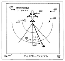
[0028]地上障害物衝突防止システム100の実施例は、航空機102の周囲の所定の領域の平面図226を生成し、検出された地上物体に関連付けられる1つ又は複数の地上物体アイコンが、生成された平面図上に示される。図2に示される例示的な平面図226は、航空機102に対応する航空機アイコン228を提示する。平面図226の範囲は、搭載機102が後方方向に移動しているとき、搭載機102の背後の所定の領域に制限される。搭載機102が前方方向に移動しているとき、平面図226の範囲は、搭載機102の前の所定の領域に制限される。いくつかの実施例では、平面図226の範囲は、搭載機102の近傍にある任意の検出された地上物体に関連付けられる任意の地上物体アイコンを示すことができるように、搭載機が停止されたとき、搭載機の周囲の所定の領域に制限される。このような実施例は、地上にいて搭載機102の近傍にいる個々を識別することができるという点で、特に有益となり得る。上述の所定の領域は同一であってもよいし異なっていてもよい。さらに、所定の領域の範囲は、人によって調整可能であってもよいし、航空機102の対地速度に基づいて自動的に調整可能であってもよい。
[0028] An embodiment of the ground obstacle
[0029]平面図226を見る航空機搭乗員及び/又は地上勤務員などの他の当事者は、航空機アイコン228の位置に基づいて、提示された平面図226における航空機102の相対的な位置を直観的に理解する。すなわち、平面図226上での航空機アイコン228の提示位置は、搭載機102の現在位置についての相対的な基準点を提供する。航空機アイコン228のために任意の適切な画像を使用することができ、ここでは航空機の輪郭として示されている。いくつかの航空機アイコン228は、航空機102が後方に移動しているときのテール、又は航空機102が前方に移動しているときの機首などの、航空機102の一部を表してもよい。
[0029] Other parties, such as an aircraft crew and / or ground crew looking at the
[0030]さらに、航空機アイコン228の提示位置は、平面図226上の任意の適切な位置にあってもよい。例えば、航空機アイコン228は、平面図226の最上部中央に配置することができる。このような上部の提示位置は、航空機102が後方(逆方向)に移動しているときに望ましい場合がある。航空機アイコン228は、平面図226のほぼ中央に配置されてもよい。このような中央の提示位置は、航空機102が停止されるとき、並びに/又は航空機102の前、背後、及び/もしくは側に地上障害物が存在し得る領域において航空機102が移動しているときに有益となり得る。航空機アイコン228は平面図226の下部に配置されてもよい。下部の提示位置は、航空機102が前方方向に移動しているときに有益となり得る。
[0030] Further, the presentation position of the
[0031]いくつかの実施例では、航空機アイコン228の提示位置は、航空機102の移動の方向に基づいて自動的に調整可能であってもよい。代替的に、又は加えて、航空機搭乗員及び/又は地上勤務員などの他の当事者は、ユーザ入力システム218を介して、航空機アイコン228の提示位置を手動で調整してもよい。さらに、平面図226上に示される平面図226の範囲(航空機102の周囲の距離の範囲)は、航空機の速度に基づいて自動的に調整可能であってもよく、並びに/又は航空機搭乗員及び/もしくは地上勤務員などの他の当事者によって手動で調整されてもよい。
[0031] In some examples, the presentation position of the
[0032]地上障害物衝突防止システム100の仮定的な動作を説明するために、地上障害物アイコン230は、背後にあり、航空機アイコン228の右にある提示位置において、平面図226上に提示される。したがって、航空機搭乗員及び/又は地上勤務員などの他の当事者は、背後にあり航空機102の右側にある潜在的な地上障害物があることを直観的に理解する。
[0032] To illustrate the hypothetical operation of the ground obstacle
[0033]いくつかの実施例は、航空機アイコン228から地上障害物アイコン230の相対的な距離を示すように構成することができる。例えば、125フィートの(必要に応じて提示される矢印234に関連付けられる)第1の距離232が、検出された地上物体が航空機102のテールの後方約125フィートにあることを示すために、平面図226上に提示される。(必要に応じて提示される矢印238に関連付けられる)20フィートの第2の例示的な距離236は、検出された地上物体が航空機102のテールの右側約20フィートにあることを示すために、平面図226上に提示される。したがって、第2の距離236は、搭載機の側(右側又は左側)に対する検出された地上障害物の距離を示す。
[0033] Some embodiments may be configured to indicate the relative distance from the
[0034]代替的に又は加えて、グリッド線242が平面図226上に提示されてもよい。ここで、例示的なグリッド線242はデカルト座標系に基づいている。このようなグリッド線242は、搭載機102からの相対距離を示す。グリッド線242は、見ている航空機搭乗員及び/又は地上勤務員などの他の当事者によって容易に理解される所定の距離の正方格子を作成するために示される。あるいは、グリッド線242は、航空機102のテール、機首又は中央などの航空機102上の選択された場所から放射状に広がる極座標系に基づいて提示することができる。グリッド線242は、航空機の他の選択された部分を基準にして提示されてもよい。例えば、グリッド線242は、航空機の翼及び/又はテールの範囲とぴったり合ってもよい(整列してもよい)。
[0034] Alternatively or in addition,
[0035]補足情報240が平面図226上に提示されてもよい。例えば、限定されるものではないが、例示的な平面図226は、航空機102の現在の対地速度が時速7.5マイル(MPH)であることを示す。必要に応じて、後方への移動方向又は前方への移動方向などの移動方向が示されてもよい。関心のある任意の適切な情報は、任意の適切な提示位置において平面図226上に含まれてもよい。
[0035]
[0036]様々な実施例では、処理システム202は、任意の適切なプロセッサ又はデバイスであってもよい。処理システム202は市販のプロセッサであってもよい。他の実施例では、処理システム202はファームウェアの実装であってもよい。処理システム202は、特別に設計されて製作されたプロセッサであってもよい。
[0036] In various embodiments, the
[0037]他のコンポーネントを必要に応じて地上障害物アラートインジケータ108に含めることができる。代替的に、地上障害物アラートインジケータ108が牽引車124のダッシュボードに統合され、航空機ディスプレイシステムに統合され、EFBに統合され、又はディスプレイを有するかディスプレイに結合される別のシステムに統合されるなどの場合、例示的な地上障害物アラートインジケータ108の1つ又は複数のコンポーネントは、他の便利な位置に存在してもよい。いくつかの実施例は、航空機衝突防止システム(ACAS)又は他の搭載される航空機警告システムに統合することができる。
[0037] Other components may be included in the ground
[0038]様々な実施例において、処理システム202は、ゲートウェイユニット106から受け取られたレーダリターン信号情報を、(検出レーダセンサモジュール104を有する)航空機102の部分の位置及び/又は当該部分からの距離(レンジ)並びに検出された地上障害物を特定するレーダ情報に対応する情報へと処理する。いくつかの実施例では、地上障害物アラートインジケータ108は、個々のレーダセンサモジュール104からレーダセンサ情報を直接受け取るように構成される。
[0038] In various embodiments, the
[0039]代替的に、ゲートウェイユニット106のいくつかの実施例は、レーダセンサモジュール104から受け取られたレーダリターン信号情報を、(検出レーダセンサモジュール104を有する)航空機の部分の位置及び/又は当該部分からの距離並びに検出された地上障害物を特定する情報へと処理してもよい。このような実施例では、ゲートウェイユニット106は、地上障害物アラートインジケータ108へ通信される、適切なアラート制御信号及び地上障害物位置情報を決定する。したがって、地上障害物アラートインジケータ108は、単に、ディスプレイ214上に提示される生成された平面図上に示される指示された地上物体に関連付けられるアイコンを提示し、及び/又は命令されたアラートを発行する。このような実施例は、地上障害物アラートインジケータ108が航空機102のコックピットで実施される場合、地上障害物アラートインジケータ108のうちの1つが牽引車124上に設置されるか又はそれに統合される場合、及び/又は、1つ又は複数の他の地上障害物アラートインジケータ108が(EFBなどの)搭乗員が携帯する携帯ハンドヘルドデバイスにおいて実施される場合などの、複数の地上障害物アラートインジケータ108が配備される場合に有用となり得る。
[0039] Alternatively, some embodiments of the
[0040]例示的な実施例では、地上障害物アラートインジケータ108は、RF信号を介してゲートウェイユニット106及び/又はレーダセンサモジュール104からレーダリターン信号情報を受け取るように構成される。RF信号処理モジュール224を実行する処理システム202は、受け取ったRF信号中のレーダリターン信号情報を、プロセッサ202による処理のために適した情報へと処理する。他の実施例は、他の無線媒体もしくは有線媒体を含む任意の適切な通信媒体を使用して、ゲートウェイユニット106及び又はレーダセンサモジュール104から情報を受け取るように構成されてもよい。
[0040] In the exemplary embodiment, ground
[0041]このようなRF通信ベースの実施例において、RF信号は、セキュリティの目的で暗号化されてもよい。代替的に、又は加えて、航空機102及び/又は地上障害物アラートインジケータ108の識別子は、牽引される航空機102のみが、現在航空機102を牽引している地上勤務員に情報を提供していることを確実にすることができる。
[0041] In such RF communication-based embodiments, the RF signal may be encrypted for security purposes. Alternatively or additionally, the identifier of aircraft 102 and / or ground
[0042]様々な実施例において、トランシーバ220は、ゲートウェイユニット106又は別のデバイスからRF信号を受け取るように構成された受信機デバイスである。例えば、ユーザインターフェース処理モジュール222及び/又はRF信号処理モジュール224に対するソフトウェアの更新又はソフトウェアの変更を、随時受け取ることができる。他の実施例では、トランシーバ220はまた、ゲートウェイユニット106又は別のデバイスにRF信号を送るように構成された送信機デバイスであってもよい。例えば、アラートの発行の確認が、検出された地上障害物との可能性のある衝突について地上クルーに通知されたことを確認するために送られてもよい。
[0042] In various embodiments, transceiver 220 is a receiver device configured to receive an RF signal from
[0043]電源モジュール204が、地上障害物アラートインジケータ108の1つ又は複数のコンポーネントに電力を供給するために含められてもよい。いくつかの状況では、地上障害物アラートインジケータ108のコンポーネントの電流及び/又は電圧の要件は、牽引車124の電源によって又は地上障害物アラートインジケータ108に設置された電池によって供給される電力(電圧及び/又は電流)とは異なってもよい。したがって、電源モジュール204は、受け取られる電力の電圧特性及び/又は電流特性を変更するなどすることによって、受け取られる電力を調整するように構成することができる。例えば、電源モジュール204の実施例は、変圧器、DC/DC電圧変換器、及び/又はDC/AC変換器を含むことができる。任意の適切な電源モジュール204、及び/又は適切なコンポーネントを使用することができる。
[0043] A
[0044]ユーザ入力システム218は、地上障害物アラートインジケータ108の様々な動作特性を制御するために、ボタン、ダイヤルなどの複数のコントローラを含んでもよい。ユーザインターフェース処理モジュール222を実行する処理システム202は、これらの動作特性に対するユーザーの変更を実施することができる。いくつかの実施例において、ディスプレイ214は、コントローラが調整可能なグラフィックアイコンなどとして示されるタッチスクリーンであってもよい。
[0044] The
[0045]例示的な実施例では、コントローラは、ディスプレイの光出力強度を現在の周囲照明条件に基づいて調整することができるように、ディスプレイ214の照明強度を調整するように構成することができる。別の例として、コントローラは、出力される音が背景雑音レベルについて調整することができるように、出力される可聴の警告又はアラームの音量を調整するように構成することができる。
[0045] In an exemplary embodiment, the controller can be configured to adjust the illumination intensity of the
[0046]図3は、レーダセンサモジュール104の例示的な実施例のブロック図である。レーダセンサモジュール104は、レーダシステム302、処理システム304、オプションの電源モジュール306、無線周波数(RF)通信システム308、及びオプションのメモリ310を含む。レーダシステム302は、レーダエミッタ312、アンテナ314、及びレーダ検出器316を含む。RF通信システム308は少なくともトランシーバを含む。いくつかの実施例において、トランシーバ318は適切なRF送信機デバイスに限定することができる。メモリ310は、レーダ信号処理モジュール320及びRF信号処理モジュール322を格納するための部分を含む。
FIG. 3 is a block diagram of an exemplary embodiment of the
[0047]処理システム304は任意の適切なプロセッサ又はデバイスとすることができる。処理システム304は市販のプロセッサであってもよい。他の実施例では、処理システム304はファームウェアの実装であってもよい。処理システム304は、特別に設計されて製作されたプロセッサであってもよい。
[0047] The
[0048]他のコンポーネントが、レーダセンサモジュール104に任意に含まれてもよい。例示的な実施例では、レーダセンサモジュール104は、航空機のライトモジュール(固定具(fixture))に統合される。航空機のライトは航空機102の様々な最も離れた範囲に配置することができるので、レーダセンサモジュール104は、地上障害物との衝突についての最も予想されるポイントに配置される。あるいは、例示的なレーダセンサモジュール104の1つ又は複数のコンポーネントは、航空機102の他の便利な位置に存在してもよいし、さらに、関心のある任意の適切な位置において、航空機の外表面に取り付けられ又は固定される、スタンドアロンのデバイスであってもよい。
[0048] Other components may optionally be included in the
[0049]新世代の高強度発光ダイオード(LED)ランプは、航空機の照明用途にとってますます利用可能になってきている。従来の航空機ライトモジュールに使用される従来の白熱ランプ又は他のタイプのランプと比較して、LEDのサイズが比較的小さいので、光モジュール内の空きスペースや空いている場所が利用可能となり得る。様々な実施例では、レーダセンサ及び他の電子デバイスが光モジュールに組み込まれてレーダセンサモジュール104を形成する。照明器具ベースの(light fixture-based)レーダセンサモジュールは、航空機102の外面上の既存の光モジュールのレセプタクルに固定可能に結合するように設計される。
[0049] New generation high intensity light emitting diode (LED) lamps are becoming increasingly available for aircraft lighting applications. Compared to conventional incandescent lamps or other types of lamps used in conventional aircraft light modules, the size of the LEDs is relatively small, so that free space or empty space in the light module may be available. In various embodiments, radar sensors and other electronic devices are incorporated into the optical module to form the
[0050]さらに、レーダセンサモジュール102は、無線周波数(RF)媒体又は他の適切な無線信号媒体を用いてレーダ情報を通信するようにさらに構成することができる。 RF通信システム308は、ゲートウェイユニット106により受け取られるRF信号を生成して送信する。いくつかの実施例では、トランシーバ318は、少なくともゲートウェイユニット106によって検出可能である距離についてのレーダリターン信号情報を送信するか又は通信する、RF送信機である。他の実施例において、トランシーバ318は、ゲートウェイユニット106又は別のデバイスからRF信号を受け取るように構成される。例えば、レーダ信号処理モジュール320及び/又はRF信号処理モジュール322に対するソフトウェアの更新又はソフトウェアの変更を随時受け取ることができる。
[0050] Further, the radar sensor module 102 can be further configured to communicate radar information using a radio frequency (RF) medium or other suitable radio signal medium. The
[0051]このようなRF信号ベースの実施例は既存の航空機102のための改造(retrofits)に特に適している。さらに、地上障害物衝突防止システム100を従来の航空機102に追加するために追加の配線や構造変更(又は少なくとも最小限の配線や構造の変更)が必要とされないので、航空機に対する変更についての規制当局による審査及び承認を回避することができるか、又は少なくとも軽減することができる。
[0051] Such RF signal based embodiments are particularly suitable for retrofits for existing aircraft 102. Further, since no additional wiring or structural changes (or at least minimal wiring or structural changes) are required to add the ground obstacle
[0052]レーダエミッタ312は、関心のある方向にアンテナ314から放出されるレーダ信号を生成するように構成される。アンテナ314は、レーダエミッタ312の検出範囲内にある任意の地上障害物から反射され得るレーダリターン信号を受け取るようにさらに構成される。レーダ検出器316は、アンテナ314からレーダリターン信号を受け取り、受け取られたレーダリターン信号をレーダリターン信号情報へと処理する。レーダリターン信号は、近くの地上障害物から反射される放射されたレーダ信号の反射に関連付けられる。
[0052] The
[0053]処理システム304は、レーダ検出器316からレーダリターン信号情報を受け取るように構成される。いくつかの実施例では、レーダ信号処理モジュール320を実行する処理システム304は、さらに、レーダリターン信号情報を、任意の検出された地上障害物の位置及び/又はそれまでの距離を特定するレーダ情報に対応する情報へと処理してもよい。RF信号処理モジュール322を実行する処理システム304は、レーダリターン信号情報を、RF通信システム308によりRF信号で通信するのに適した情報へと処理する。
[0053] The
[0054]電源モジュール306は、レーダセンサモジュール104の1つ又は複数のコンポーネントに電力を提供するために含めることができる。いくつかの状況では、レーダセンサモジュール104のコンポーネントの電流及び/又は電圧の要件は、レーダセンサモジュール104を内部に有する航空機ライトのLEDを照明するために供給される電力(電圧及び/又は電流)と異なっていてもよい。電源モジュール306は、好ましくは、改造用途の場合には既存の電源コンポーネント及びコネクタを使用して、航空機102から十分な量の電力を受け取るように構成される。電源モジュール306はまた、受け取られた電力の電圧特性及び/又は電流特性を変化させることなどによって、受け取られた電力を調整するように構成されてもよい。例えば、電源モジュール306の実施例は、変圧器、DC/DC電圧変換器、及び/又はDC/AC変換器を含むことができる。任意の適切な電源モジュール306、及び/又は適切なコンポーネントを使用することができる。
[0054] A
[0055]内部にレーダセンサモジュール104を有する航空機ライトモジュールは、好ましくは、航空機ライトモジュールの交換中に、航空機102上の対応する結合ユニットの嵌合コネクタから容易に切り離すことができる複数のコネクタを含む。結合ユニットにおける1つ又は複数のコネクタは、LED又は他のタイプのランプの照明のための電力を受け取るように構成される。例示的な実施例では、航空機ライトモジュールが地上走行中などにオンされる(作動される)とき、レーダセンサモジュール104は、電力を受け取り、動作可能になる。航空機ライトモジュールがオフである(非活性化される)とき、電力はレーダセンサモジュール104に提供されず、したがって、動作可能ではない。
[0055] The aircraft light module having the
[0056]他の実施例では、電力は電力接続を介して継続的に利用可能である。制御信号が航空機ライトモジュールに提供され、航空機ライトモジュールのLEDの照明を引き起こす。このような実施例では、電力はレーダセンサモジュール104にとって継続的に利用可能である。いくつかの実施例では、レーダセンサモジュール104は継続的に動作可能であり、したがって、レーダエミッタ312の検出範囲内にある任意の障害物や危険の存在を検出している。
[0056] In other embodiments, power is continuously available over the power connection. A control signal is provided to the aircraft light module to cause illumination of the LED of the aircraft light module. In such embodiments, power is continuously available to the
[0057]他の実施例では、地上勤務員や他のオペレータは、レーダセンサモジュール104を動作可能にさせる制御信号を提供する。代替的に、又は加えて、レーダセンサモジュール104を動作可能にさせる制御信号は、限定はされないが、航空機102を牽引するのに使用されるデバイスに関連付けられるコントローラなどの、別の電子システム又は電子デバイスによって提供される。
[0057] In other embodiments, ground workers and other operators provide control signals that enable the
[0058]様々な実施例において、放出されるレーダ信号が、関心のある方向に、又は地上障害物との可能性のある衝突の発生に関連付けられる視野(FOV)において放射されるように、レーダエミッタ312の向きが選択される。例えば、レーダエミッタ312は、翼110の先に配置されるとき、翼110、112の同じ高さにおいて物体の存在を検出するために、水平面に沿って方向づけられてもよい。いくつかの実施例では、レーダエミッタ312はまた、翼110、112の前にある物体を感知するように、前向きの方向に方向づけられてもよい。代替的に、又は加えて、レーダエミッタ312はまた、翼110、112の背後にある物体を感知するように、後ろ向きの方向に方向づけられてもよい。いくつかの実施例では、複数のレーダエミッタ312は、関心のある領域に関するレーダカバレッジを提供するために使用されてもよい。例えば、限定はされないが、2つのレーダエミッタ312を用いることができ、1つは前向きに方向づけられ、1つは後ろ向きに方向づけられてもよい。レーダセンサモジュール104の実施例は、任意の所望の数のレーダエミッタ312を使用することができる。さらに、実施例は、レーダ信号を放出し、レーダ反射を受け取って検出するために必要な、任意の適切な数のアンテナ314及び/又はレーダ検出器316を含むことができる。
[0058] In various embodiments, the radar is such that emitted radar signals are emitted in the direction of interest or in the field of view (FOV) associated with the occurrence of a potential collision with a ground obstacle. The orientation of the
[0059]レーダセンサモジュール104の視野(FOV)は、航空機102の周りの空間の領域の所望のカバレッジを提供する。FOVパラメータは一般的な事故の形状及び機能の要件(typical accident geometry and functional requirements)から導出される。航空機102の周囲の任意の死角は、1つの候補となる技術(レーダ)の視野及び光モジュール内にレーダを配置することに関連する制約に基づく。他のFOVは、レーダシステム302が光モジュール内に配置される場所に応じて可能である。
[0059] The field of view (FOV) of the
[0060]センサのFOVの閾値は、航空機102の着陸に必要な空間の特定の領域に基づいて評価することができる。さらに、センサのFOVは、航空機102の移動中の危険や障害物からの最小距離閾値を指定する規制要件に基づいて定義することができる。 [0060] The FOV threshold of the sensor may be evaluated based on a particular area of space required for the landing of the aircraft 102. Further, the FOV of the sensor can be defined based on regulatory requirements that specify a minimum distance threshold from danger and obstacles while the aircraft 102 is moving.
[0061]例示的な実施例では、レーダセンサモジュール104及びゲートウェイユニット106は、ハネウェル社製の、ACASシステム要件に適合する、OneWireless(商標)デバイスを含む。適切なリンクパワーバジェットを確保するために、特別なアンテナがこれらのデバイスと共に使用される。802.11(WLAN)無線技術などの他の無線プロトコルを使用してもよい。
[0061] In an exemplary embodiment,
[0062]図4は、ゲートウェイユニット106の例示的な実施例のブロック図である。ゲートウェイユニット106は、処理システム402、電源モジュール404、RF通信システム406、メモリ408、及びオプションのユーザインターフェースシステム410を含む。RF通信システム406はトランシーバ412を含む。ユーザインターフェースシステム410は、任意のディスプレイ416を備えたディスプレイシステム414、オプションの可聴警告システム418、及びオプションのユーザ入力420を含む。メモリ408は、レーダ情報処理モジュール422及びRF信号処理モジュール424を格納するための部分を含む。
FIG. 4 is a block diagram of an exemplary embodiment of
[0063]処理システム402は任意の適切なプロセッサ又はデバイスであってもよい。処理システム402は市販のプロセッサであってもよい。他の実施例では、処理システム402はファームウェアの実装であってもよい。処理システム402は、特別に設計されて製造されたプロセッサであってもよい。いくつかの実施例では、処理システム402は、レーダセンサモジュール104から又はRF通信システム406からレーダ情報を受け取る、別のシステム又はデバイスのコンポーネントであってもよい。
[0063] The
[0064]他のコンポーネントを、必要に応じて、ゲートウェイユニット106に含めてもよい。代替的に、例示的なゲートウェイユニット106の1つ又は複数のコンポーネントは、航空機102内の他の便利な位置に存在してもよい。
[0064] Other components may be included in the
[0065]例示的な実施例では、RF通信システム406は、レーダセンサモジュール104によって送られたRF信号を受け取る。このような実施例では、トランシーバ412は、少なくともレーダセンサモジュール104のブロードキャスト範囲内にある距離について通信されたレーダリターン信号情報を受け取る、RF受信機である。様々な実施例では、トランシーバ412は、RF信号をレーダセンサモジュール104又は別のデバイスに送るように構成することができる。例えば、レーダセンサモジュール104内のレーダ情報処理モジュール422及び/又はRF信号処理モジュール424に対する更新又は変更が、随時送られてもよい。
[0065] In the exemplary embodiment, the
[0066]有線ベースの通信媒体を用いて1つ又は複数のレーダセンサモジュール104からレーダ情報を受け取るように構成された有線ベースの実施例において、例示的なRF通信システム406は、適切な有線ベースの通信システムで置き換えることができる。いくつかの実施例は、レーダセンサモジュール104への及び/又は他のデバイスからのRF信号と有線ベースの信号の両方を受け取るように構成することができる。
[0066] In a wired-based embodiment configured to receive radar information from one or more
[0067]RF信号処理モジュール424を実行する処理システム402は、レーダセンサモジュール104から受け取ったRF信号情報を、レーダ情報へと処理する。レーダ情報処理モジュール422を実行する処理システム402は、さらに、レーダ情報を、地上障害物アラートインジケータ108と通信するのに適しているアラート情報へと処理する。
[0067] The
[0068]いくつかの実施例では、オプションの(optional)ユーザインターフェースシステム410は、レーダセンサモジュール104の検出範囲内にある任意の検出された障害物や危険についての警告及び/又は勧告を提供するために使用することができる。例えば、ゲートウェイユニット106は航空機102のコックピット内に配置されてもよい。このような実施例では、処理システム402は、任意のディスプレイ416上に提示することができるグラフィック表示情報を生成する。ディスプレイ416上に提示されるグラフィック情報は、地上障害物アラートインジケータ108によって提供される平面図226と同様であってもよい。したがって、ディスプレイ416を見る搭乗員は、彼らの航空機が地上走行されているか又は他の方法で地上勤務員によって移動されているときに、レーダセンサモジュール104の検出範囲内にある任意の検出された障害物や危険の性質を理解する。したがって、牽引中に存在する場合、航空機102の搭乗員は、地上勤務員と同じアラートを受け取る。
[0068] In some embodiments, the optional user interface system 410 provides warnings and / or recommendations for any detected obstacles or hazards that are within the detection range of the
[0069]代替的に、又は加えて、グラフィック表示情報は、リモートディスプレイに通信することができ、及び/又は別のシステムに通信することができる。例えば、グラフィック表示情報は、電子フライトバッグなどに伝達することができる。代替的に、又は加えて、グラフィック表示情報は搭載されたレーダデバイスに伝達することができる。 [0069] Alternatively or additionally, the graphical display information can be communicated to a remote display and / or can be communicated to another system. For example, the graphic display information can be transmitted to an electronic flight bag or the like. Alternatively or additionally, the graphic display information can be communicated to an onboard radar device.
[0070]いくつかの実施例では、可聴警告システム418は、任意の物体がレーダセンサモジュール104の検出範囲内にある場合に、航空機102の搭乗員に対して可聴の警告やアラートを発するように構成することができる。可聴警告システム418は航空機102のキャビン内の便利な位置に配置することができる。他の実施例では、可聴アラート又は警告を発することができるように、信号を別の可聴警告システムに通信してもよい。
[0070] In some embodiments, the audible warning system 418 may issue an audible warning or alert to a crew member of the aircraft 102 when any object is within the detection range of the
[0071]ユーザ入力システム420は、航空機102の搭乗員又は整備員などの別の個人からの入力を受け取るように構成される。いくつかの実施例では、ユーザ入力システム420は、ゲートウェイユニット106、1つもしくは複数のレーダセンサモジュール104、及び/又は1つもしくは複数の地上障害物アラートインジケータ108の動作を作動させるコマンドを入力するために使用してもよい。加えて、又は代替的に、任意の障害物又は危険が航空機102からの距離閾値内にある場合に、搭乗員は、アラートを生成するために使用される距離閾値を設定及び/又は調整することができる。
[0071] The
[0072]オプションの電源モジュール404は、ゲートウェイユニット106のコンポーネントに電力を供給する。航空機102が地上障害物衝突防止システム100の実施例によって改造される場合、航空機102上の単一の便利にアクセス可能な電源を、電源モジュール404に供給することができる。電源モジュール404は、ゲートウェイユニット106の1つ又は複数のコンポーネントに電力を供給することができる。
[0072] The optional power supply module 404 provides power to the components of the
[0073]いくつかの状況では、ゲートウェイユニット106のコンポーネントの電流及び/又は電圧の要件は、アクセスされる電力(電圧及び/又は電流)と異なっていてもよい。このような場合には、電源モジュール404は、受け取られる電力の電圧特性及び/又は電流特性を変化させることなどによって、受け取られる電力を調整するように構成される。例えば、電源モジュール404の実施例は、変圧器、DC/DC電圧変換器、及び/又はDC/AC変換器を含むことができる。当業者によって理解されるように、任意の適切な電源モジュール404及び/又は適切なコンポーネントを使用することができる。
[0073] In some situations, the current and / or voltage requirements of the components of the
[0074]図5は、限定はされないが、ナビゲーション/位置灯又は衝突防止灯などの、レーダセンサモジュール104を備える例示的な航空機ライトの例示的なライトコンパートメント(light compartment)502を示す。コンパートメント502は、(照明バージョンの要件に基づいて)2つのLEDアセンブリ又は2つのハロゲン電球504を備えた位置灯504を含む。光コンパートメント502は次のものを含む。
[0074] FIG. 5 illustrates an
・アンテナ−例えば2−4cmである。アンテナはガラスカバー506の背後に配置される。他の部分は、信号の減衰を増加させるアルミニウム又は複合材料で作られる。
・ガラス506の上又は中に取り付けられたアンテナを備えたレーダセンサモジュール104。
• Antenna-eg 2-4 cm. The antenna is disposed behind the
A
[0075]例示的な実施例では、レーダシステム302は、関連する電子機器を有する、産業用、科学的、及び医療用(industrial, scientific, and medical、ISM)2.4GHz帯の距離測定レーダである。1つの実施例では、ゲートウェイユニット106のISM帯無線通信のためのセンサノードアンテナは、位置灯コンパートメントに含まれる。1つの実施例では、アンテナは、RF信号通信のために透明であると予期される軽いガラス光カバーの下に配置される。アンテナはまた、ゲートウェイユニット106とのエラーのない通信のための十分な利得を提供する。
[0075] In an exemplary embodiment,
[0076]いくつかの実施例では、指向性アンテナが使用される。指向性アンテナは全方向性ダイポールよりも多くのスペースを必要とする。基本的に、少なくとも2つの適切な指向性アンテナの種類、八木アンテナ及びパッチアンテナがある。これらの両方は指向性の特性を提供するが、任意の適切なアンテナ314を使用することができる。八木アンテナは、メインローブの方向に平坦で長い。パッチアンテナは、メインローブ軸に垂直な平面においてより多くのスペースを必要とする。これは、八木アンテナのフロント要素が位置灯と干渉する可能性があることを意味する。他方、パッチアンテナは、位置灯コンポーネント(LEDリフレクタ、レーダアンテナレンズ)の間により大きなスペースを必要とする。
[0076] In some embodiments, a directional antenna is used. Directional antennas require more space than omnidirectional dipoles. Basically, there are at least two suitable directional antenna types, Yagi antenna and patch antenna. Both of these provide directional characteristics, but any
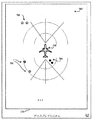
[0077]図6は代替的な平面図602を示す。本実施例では、検出された地上障害物からの距離が矢印604を用いて示される。テキスト606は、航空機102からの、又はテールなどの航空機102の所定の部分からの地上物体のレンジ(距離)を示す。ここで、グリッド線608は極座標系を使用して提示される。
[0077] FIG. 6 shows an
[0078]いくつかの実施例では、人を地上障害物として識別することができる。例えば、提示される地上障害物アイコン610が検出された人に対応する。ここで、地上障害物アイコン610は、人又は個人の画像として提示される。したがって、航空機の搭乗員は、航空機102に近接するときに地上勤務員の位置を容易に理解する。 [0078] In some embodiments, a person can be identified as a ground obstacle. For example, it corresponds to the person from whom the presented ground obstacle icon 610 is detected. Here, the ground obstacle icon 610 is presented as an image of a person or an individual. Thus, aircraft crews readily understand the location of ground workers when approaching the aircraft 102.
[0079]様々な実施例では、レーダエミッタ312、レーダアンテナ314、及びレーダ検出器316は、それぞれのレーダセンサモジュール104に近接する地上障害物を識別するためにレーダ情報を取得するように、協調して動作する。レーダエミッタ312により放出されるレーダ信号の強度、レーダアンテナ314の指向性、及び/又はレーダ検出器316の感度に基づいて、レーダセンサモジュール104は、十分に近接していて航空機102の一部との衝突を引き起こす可能性があり得る地上障害物を検出することができる。しかし、レーダセンサモジュール104はまた、航空機102から十分に遠く離れていて潜在的な衝突の危険とならない地上障害物を検出してもよい。したがって、地上障害物衝突防止システム100の実施例は、十分に近接していて衝突を引き起こす可能性があり得る検出された地上障害物と、衝突を引き起こすには十分に近接していない検出された地上障害物とを区別するように構成される。
[0079] In various embodiments,
[0080]例示的な実施例において、レーダエミッタ312により放出されるレーダ信号の強度、レーダアンテナ314の指向性、及び/又はレーダ検出器316の感度のうちの少なくとも1つは、レーダセンサモジュール104の検出範囲を関連する検出範囲に制限するように構成される。地上障害物が関連する検出範囲の外にある(関連する検出範囲から遠く離れている)場合には、レーダセンサモジュール104は地上障害物を検出しない。したがって、地上障害物アラートインジケータ108はアラートを発しない。
[0080] In the exemplary embodiment, at least one of the intensity of the radar signal emitted by the
[0081]代替的に、又は加えて、検出された地上障害物からのレンジ(又は距離)が決定されてもよい。レーダセンサモジュール104からの地上障害物のレンジは、実施例に応じて、レーダセンサモジュール104、ゲートウェイユニット106、及び/又は地上障害物アラートインジケータ108によって決定することができる。
[0081] Alternatively or in addition, the range (or distance) from the detected ground obstacle may be determined. The range of ground obstacles from the
[0082]決定されたレンジは所定のレンジ閾値と比較される。決定されたレンジがレンジ閾値よりも大きい場合、地上障害物との衝突の可能性は、地上障害物アラートインジケータ108がアラートを発しないように十分に低い。他方、決定されたレンジがレンジ閾値に少なくとも等しい場合、地上障害物アラートインジケータ108はアラートを発する。決定されたレンジのレンジ閾値との比較は、実施例に応じて、レーダセンサモジュール104、ゲートウェイユニット106、及び/又は地上障害物アラートインジケータ108によって実行することができる。
[0082] The determined range is compared to a predetermined range threshold. If the determined range is greater than the range threshold, the probability of a collision with a ground obstacle is low enough so that the ground
[0083]いくつかの実施例では、複数のレンジ閾値を使用することができる。異なるレンジ閾値を、地上障害物を検出する特定のレーダセンサモジュール104の特定の位置に依存して使用することができる。例えば、第1のレンジ閾値は航空機102の翼端に位置するレーダセンサモジュール104のために使用することができ、第2のレンジ閾値(第1のレンジ閾値より小さい)は航空機102の後部に位置するレーダセンサモジュール104のために使用することができ、第3のレンジ閾値(第1のレンジ閾値及び/又は第2のレンジ閾値より小さい)は航空機102のエンジン122上に位置するレーダセンサモジュール104のために使用することができる。
[0083] In some embodiments, multiple range thresholds may be used. Different range thresholds can be used depending on the particular location of the particular
[0084]加えて、又は代替的に、第1のレンジ閾値は警告タイプのアラートを生成するために使用することができる。そして、第2のレンジ閾値(第1のレンジ閾値より小さい)はアラームタイプのアラートを生成するために使用することができる。他のレンジ閾値は、他のアラートレベルを区別するために使用することができる。 [0084] Additionally or alternatively, the first range threshold can be used to generate a warning type alert. The second range threshold (less than the first range threshold) can then be used to generate an alarm type alert. Other range thresholds can be used to distinguish other alert levels.
[0085]さらに、所定のレンジ閾値は調整可能であってもよい。いくつかの実施例では、地上勤務員又は他の職員は、レンジ閾値を選択的に指定するか又は調整することができる。代替的に、又は加えて、レンジ閾値は、牽引されるときに、航空機の速度及び/又は方向に基づいて自動的に調整することができる。レンジ閾値に対する調整は、実施例に応じて、レーダセンサモジュール104、ゲートウェイユニット106、及び/又は地上障害物アラートインジケータ108によって実行されてもよい。
[0085] Further, the predetermined range threshold may be adjustable. In some embodiments, ground staff or other personnel can selectively specify or adjust the range threshold. Alternatively or additionally, the range threshold can be automatically adjusted based on the speed and / or direction of the aircraft when towed. Adjustments to range thresholds may be performed by
[0086]代替的な実施例では、1つ又は複数のセンサモジュールは、別のタイプのセンサを使用することができる。すなわち、レーダセンサではなく、センサモジュールは、音響、ソナー、又は光信号感知に基づいてもよい。 [0086] In alternative embodiments, the one or more sensor modules may use other types of sensors. That is, rather than a radar sensor, the sensor module may be based on acoustic, sonar, or optical signal sensing.
[0087]例示的な実施例では、エミッタは、音響信号を発するスピーカなどの音響エミッタである。いくつかの実施例では、放出された音は、人間が認識できない周波数を有してもよい。検出器は、地上障害物からの反射された音を検出する、マイクロフォンなどの音響検出器である。 [0087] In an exemplary embodiment, the emitter is an acoustic emitter, such as a speaker that emits an acoustic signal. In some embodiments, the emitted sound may have a frequency that humans cannot recognize. The detector is an acoustic detector such as a microphone that detects reflected sound from a ground obstacle.
[0088]別の例示的な実施例では、エミッタは光信号を発する発光体である。いくつかの実施例では、放出された光は、赤外光、紫外光などの、人間が認識できない周波数を有してもよい。検出器は、地上障害物からの反射光を検出する光検出器である。 [0088] In another exemplary embodiment, the emitter is a light emitter that emits an optical signal. In some embodiments, the emitted light may have a frequency that humans cannot recognize, such as infrared light or ultraviolet light. The detector is a photodetector that detects reflected light from a ground obstacle.
[0089]さらに別の例示的な実施例では、検出器は、航空機上のライトによって放出される光、他のランプによって放出されるかもしくは他の照明器具から放出される光、又は周囲光からの光に基づいて視覚映像を処理するカメラであってもよい。画像処理技術は、航空機が衝突し得る物体からのレンジを特定するために使用することができる。 [0089] In yet another exemplary embodiment, the detector is from light emitted by lights on an aircraft, light emitted by other lamps or emitted from other luminaires, or ambient light. It may be a camera that processes visual images based on the light. Image processing techniques can be used to identify ranges from objects that an aircraft can collide with.
[0090]他の実施例では、レーザ検出及び測距(LIDAR)システムを使用してもよい。不可視の光エネルギーを放出するように構成された他の発光体を使用することができ、検出器は物体の存在を検出するように構成される。 [0090] In other embodiments, a laser detection and ranging (LIDAR) system may be used. Other light emitters configured to emit invisible light energy can be used and the detector is configured to detect the presence of an object.
[0091]したがって、複数のセンサモジュールの各々は、センサを用いて地上障害物を検出し、検出された地上障害物に関連付けられる情報をゲートウェイユニット106に送り、複数のセンサモジュールの各々は、航空機がけん引されている間に地上障害物との接触の危険がある航空機の表面上に一意的に配置される。そして、ゲートウェイユニットにおいて、センサモジュールから送られた情報が受け取られる。そして、受け取られたセンサ情報に関連付けられた情報が、地上物体アラートインジケータに送られる。
[0091] Accordingly, each of the plurality of sensor modules detects a ground obstacle using the sensor and sends information associated with the detected ground obstacle to the
[0092]図7は、航空機102に近接した複数の検出された地上物体アイコン704、706、708を示す代替的な平面図702を示す。航空機102の周りの大きな領域を包含する平面図を提示するように、平面図702の範囲は十分に大きい。
[0092] FIG. 7 shows an
[0093]ここで、検出された地上物体アイコン704は、(航空機アイコン228で示される)航空機102に比較的近接している。検出された地上物体アイコン704に関連付けられる検出された地上物体が航空機102に対する危険を及ぼすことがあるので、検出された地上物体アイコン704は第1の色で(ここでは、黒の陰影で)示される。関連付けられる地上物体が航空機102に対する潜在的な危険であり得ることを、提示された検出された地上物体アイコン704が示すように、照明レベルは非常に明るくしてもよい。
[0093] Here, the detected
[0094]さらに、他の検出された地上物体アイコン706は、(航空機アイコン228で示される)航空機102に近接しているが、提示される検出された地上物体アイコン704からさらに遠い。検出された地上物体アイコン706に関連付けられる検出された地上物体は単に航空機102に対する危険の最小の可能性を提示する可能性があるので、検出された地上物体アイコン706は第2の色で(ここでは、灰色の陰影で)示される。関連付けられる地上物体の航空機102に対する潜在的な危険がより小さいことを示すために、照明レベルは(提示される検出された地上物体アイコン704の照明レベルより)明るくしてもよい。
[0094] Further, other detected
[0095]検出された地上物体アイコン708は(航空機アイコン228によって示される)航空機102から比較的遠く離れている。検出された地上物体アイコン708に関連付けられる検出された地上物体は航空機102に対して危険を及ぼさないので、検出された地上物体アイコン704は第3の色で(ここでは、白の陰影で)示される。関連付けられる地上物体が航空機102に対する潜在的な危険である可能性が低いことを、提示される検出された地上物体アイコン708が示すために、照明レベルは比較的低くてもよい。
[0095] The detected
[0096]いくつかの実施例では、検出された地上物体に関連付けられた特定の地上物体アイコンは、検出された地上物体の他の特性を示すために、異なる形状及び/又は輪郭を使用してもよい。例えば、検出された地上物体が牽引車124である場合、提示される地上物体アイコンは、牽引車の輪郭、牽引車の線画、又は牽引車の写真の形態であってもよい。別の限定的でない例として、検出された地上物体が別の航空機である場合、提示される地上物体アイコンは航空機の形態であってもよい。別の限定的でない例として、検出された地上物体が人である場合、提示される地上物体アイコンは、個人の輪郭の形態であるか、又は線描画(stick figured)(いくつかの線、曲線及び/又は点からなる、人物の非常に単純な描画)であってもよい。
[0096] In some embodiments, a particular ground object icon associated with a detected ground object uses a different shape and / or contour to indicate other characteristics of the detected ground object. Also good. For example, if the detected ground object is a
[0097]いくつかの実施例では、検出された地上物体の高さは、様々なセンサによって収集された情報から決定することができる。検出された地上物体の高さに関する高さ情報が利用可能である場合、検出された地上物体の高さは提示された平面図226上にテキストとして示されてもよい。
[0097] In some embodiments, the height of a detected ground object can be determined from information collected by various sensors. If height information regarding the height of the detected ground object is available, the height of the detected ground object may be shown as text on the presented
[0098]例えば、検出された地上物体の高さが「3フィート」であることを示すテキストが平面図226上に示されてもよい。この高さは十分に低く、航空機102の翼が検出された地上物体の上を安全に通過することができる。したがって、航空機102はその計画された経路を変更する必要はないかもしれない。
[0098] For example, text indicating that the height of the detected ground object is "3 feet" may be shown on the
[0099]他方、検出された地上物体の高さが「20フィート」であることがあり、平面図226上に示されてもよい。この高さは、航空機102の翼が安全に上を通過するには高すぎることがある。したがって、航空機102は、その計画された経路を変更するか、又は地上物体が移動されるまで停止する必要があるかもしれない。
[0099] On the other hand, the height of the detected ground object may be “20 feet” and may be shown on a
Claims (20)
搭載機の外部上の選択された異なる位置に各々が配置される複数のレーダセンサモジュールであって、各レーダセンサモジュールが、
レーダ信号を放出するように構成されるレーダエミッタ、及び
地上障害物から反射される放出されたレーダ信号の反射に関連付けられるレーダリターン信号を受け取るように構成されるレーダ検出器を含み、
前記レーダセンサモジュールは、前記検出されたレーダリターン信号に対応するレーダ情報を通信する、複数のレーダセンサモジュールと、
前記搭載機から前記複数のレーダセンサモジュールのうちの少なくとも1つによって検出される検出された地上物体までの距離を決定するように構成される処理システムと、
少なくとも1つの航空機アイコン及び前記検出された地上障害物に関連付けられるグラフィカルな地上障害物アイコンを示す平面図を提示するように構成されるディスプレイと
を備え、
前記平面図上の前記航空機アイコンの提示位置は、前記搭載機についての相対的な基準点を提供し、
前記グラフィカルな地上障害物アイコンの提示位置は、前記搭載機に対する前記検出された地上物体の位置に関連して示される地上物体衝突防止システム。 A ground object collision prevention system,
A plurality of radar sensor modules each arranged at a different selected position on the outside of the onboard machine, each radar sensor module comprising:
A radar emitter configured to emit a radar signal, and a radar detector configured to receive a radar return signal associated with a reflection of the emitted radar signal reflected from a ground obstacle;
The radar sensor module communicates radar information corresponding to the detected radar return signal, and a plurality of radar sensor modules;
A processing system configured to determine a distance from the onboard machine to a detected ground object detected by at least one of the plurality of radar sensor modules;
A display configured to present a top view showing at least one aircraft icon and a graphical ground obstacle icon associated with the detected ground obstacle;
The presentation position of the aircraft icon on the plan view provides a relative reference point for the onboard machine;
A ground object collision prevention system in which a presentation position of the graphical ground obstacle icon is shown in relation to the position of the detected ground object with respect to the onboard machine.
をさらに備え、
前記複数のレーダセンサモジュールは、各々が、前記受け取られたレーダリターン信号に関連付けられる前記レーダ情報を無線で送るように構成される無線周波数(RF)システムをさらに含み、
前記ゲートウェイユニットは、前記複数のレーダセンサモジュールから送られた前記レーダ情報を無線で受け取るように構成される前記RFシステムをさらに含む請求項1に記載のシステム。 A gateway unit coupled to the plurality of radar sensor modules and configured to receive the radar information communicated from the plurality of radar sensor modules;
The plurality of radar sensor modules further include a radio frequency (RF) system, each configured to wirelessly transmit the radar information associated with the received radar return signal;
The system of claim 1, wherein the gateway unit further comprises the RF system configured to wirelessly receive the radar information sent from the plurality of radar sensor modules.
レーダエミッタからレーダ信号を放出するステップと、
レーダ検出器において、地上障害物からの前記放出されたレーダ信号の反射に対応するレーダリターン信号を受け取るステップと、
前記地上障害物から反射される前記受け取られたレーダリターン信号の反射に関連付けられるレーダ情報を送るステップと、
前記複数のレーダセンサモジュールの各々は、前記航空機が牽引されている間に前記地上障害物との衝突の危険がある航空機の表面上に一意的に配置され、
ゲートウェイユニットにおいて、
前記レーダセンサモジュールから送られた前記レーダ情報を受け取るステップと、
前記受け取られたレーダ情報に関連付けられる情報を送るステップと、
処理システムにおいて、前記搭載機から前記複数のレーダセンサモジュールのうちの少なくとも1つによって検出される検出された地上物体までの距離を決定するステップと、
ディスプレイ上で、少なくとも1つの航空機アイコン及び前記検出された地上障害物に関連付けられるグラフィカルな地上障害物アイコンを示す平面図を提示するステップと
を含み、
前記平面図上の前記航空機アイコンの提示位置は前記搭載機についての相対的な基準点を提供し、
前記グラフィカルな地上障害物アイコンの提示位置は前記搭載機に対する前記検出された地上物体の位置に関して示される方法。 In each of the plurality of radar sensor modules,
Emitting a radar signal from a radar emitter;
Receiving in a radar detector a radar return signal corresponding to a reflection of the emitted radar signal from a ground obstacle;
Sending radar information associated with a reflection of the received radar return signal reflected from the ground obstacle;
Each of the plurality of radar sensor modules is uniquely disposed on a surface of the aircraft that is at risk of collision with the ground obstacle while the aircraft is being towed;
In the gateway unit,
Receiving the radar information sent from the radar sensor module;
Sending information associated with the received radar information;
In a processing system, determining a distance from the onboard machine to a detected ground object detected by at least one of the plurality of radar sensor modules;
Presenting on the display a plan view showing at least one aircraft icon and a graphical ground obstacle icon associated with the detected ground obstacle;
The presentation position of the aircraft icon on the plan view provides a relative reference point for the onboard machine;
The presentation position of the graphical ground obstacle icon is indicated with respect to the position of the detected ground object with respect to the onboard machine.
Applications Claiming Priority (7)
| Application Number | Priority Date | Filing Date | Title |
|---|---|---|---|
| US201261653297P | 2012-05-30 | 2012-05-30 | |
| US61/653,297 | 2012-05-30 | ||
| US201261706632P | 2012-09-27 | 2012-09-27 | |
| US61/706,632 | 2012-09-27 | ||
| US13/835,122 | 2013-03-15 | ||
| US13/835,122 US9581692B2 (en) | 2012-05-30 | 2013-03-15 | Collision-avoidance system for ground crew using sensors |
| PCT/US2013/043257 WO2013181334A1 (en) | 2012-05-30 | 2013-05-30 | Collision-avoidance system for ground crew using sensors |
Publications (1)
| Publication Number | Publication Date |
|---|---|
| JP2015523646A true JP2015523646A (en) | 2015-08-13 |
Family
ID=49673887
Family Applications (1)
| Application Number | Title | Priority Date | Filing Date |
|---|---|---|---|
| JP2015515173A Pending JP2015523646A (en) | 2012-05-30 | 2013-05-30 | Collision prevention system for ground workers using sensors |
Country Status (6)
| Country | Link |
|---|---|
| US (1) | US9581692B2 (en) |
| EP (1) | EP2856456A4 (en) |
| JP (1) | JP2015523646A (en) |
| CN (1) | CN104335265A (en) |
| IN (1) | IN2014DN09454A (en) |
| WO (1) | WO2013181334A1 (en) |
Cited By (2)
| Publication number | Priority date | Publication date | Assignee | Title |
|---|---|---|---|---|
| JP2020015348A (en) * | 2018-07-23 | 2020-01-30 | エスゼット ディージェイアイ テクノロジー カンパニー リミテッドSz Dji Technology Co.,Ltd | Multicopter |
| JP2020529583A (en) * | 2017-06-30 | 2020-10-08 | エイ・キューブド・バイ・エアバス・エル・エル・シー | Systems and methods for adjusting the range of lidar sensors on an aircraft |
Families Citing this family (47)
| Publication number | Priority date | Publication date | Assignee | Title |
|---|---|---|---|---|
| US8264377B2 (en) * | 2009-03-02 | 2012-09-11 | Griffith Gregory M | Aircraft collision avoidance system |
| US9581692B2 (en) | 2012-05-30 | 2017-02-28 | Honeywell International Inc. | Collision-avoidance system for ground crew using sensors |
| US9207319B2 (en) * | 2012-05-30 | 2015-12-08 | Honeywell International Inc. | Collision-avoidance system for ground crew using sensors |
| EP2901178A4 (en) | 2012-09-27 | 2016-03-30 | Honeywell Int Inc | Systems and methods for using radar-adaptive beam pattern for wingtip protection |
| CA2833985C (en) * | 2012-11-19 | 2020-07-07 | Rosemount Aerospace, Inc. | Collision avoidance system for aircraft ground operations |
| FR2999725B1 (en) * | 2012-12-18 | 2015-01-23 | Thales Sa | METHOD FOR ADJUSTING A CISION / MASKING SECTOR OF AN ENVIRONMENTAL SCRUTING DEVICE, CORRESPONDING ADJUSTER DEVICE AND TERMINAL |
| US20140336849A1 (en) * | 2013-05-08 | 2014-11-13 | Honeywell International Inc. | System and method for displaying rate-of-climb on an avionics vertical speed indicator |
| US10963133B2 (en) * | 2014-01-07 | 2021-03-30 | Honeywell International Inc. | Enhanced awareness of obstacle proximity |
| US9472109B2 (en) | 2014-01-07 | 2016-10-18 | Honeywell International Inc. | Obstacle detection system providing context awareness |
| US10431105B2 (en) | 2014-01-07 | 2019-10-01 | Honeywell International Inc. | Enhanced awareness of obstacle proximity |
| US9469416B2 (en) | 2014-03-17 | 2016-10-18 | DM3 Aviation LLC | Airplane collision avoidance |
| FR3020043B1 (en) * | 2014-04-17 | 2016-04-22 | Sagem Defense Securite | AIRCRAFT COMPRISING A RETRACTABLE ARM HAVING OBSTACLE DETECTOR |
| US9751527B2 (en) * | 2014-07-09 | 2017-09-05 | Alcatel-Lucent Usa Inc. | In-the-road, passable obstruction avoidance arrangement |
| CN105336221B (en) * | 2014-08-01 | 2017-12-08 | 深圳中集天达空港设备有限公司 | A kind of real-time capturing method and system of docking aircraft |
| KR101619599B1 (en) * | 2014-08-08 | 2016-05-10 | 현대자동차주식회사 | Vehicle Collision Avoidance Method and Apparatus of Low Power Consumption Based on Fused Radar Sensors |
| US9721475B2 (en) * | 2014-09-05 | 2017-08-01 | Honeywell International Inc. | Systems and methods for displaying object and/or approaching vehicle data within an airport moving map |
| WO2016045703A1 (en) * | 2014-09-23 | 2016-03-31 | Airbus Operations (S.A.S.) | Method and device for determining the ground collision risk of an aircraft |
| US9547993B2 (en) * | 2015-02-23 | 2017-01-17 | Honeywell International Inc. | Automated aircraft ground threat avoidance system |
| CN104749998A (en) * | 2015-03-23 | 2015-07-01 | 中国民航大学 | Automatic monitoring system for towbarless aircraft towing tractor |
| US10053231B2 (en) | 2015-10-20 | 2018-08-21 | Goodrich Lighting Systems, Inc. | Integration of aircraft exterior lighting with proximity sensing and warning |
| EP3165944B1 (en) * | 2015-11-04 | 2022-04-20 | Nxp B.V. | Embedded communication authentication |
| US10288890B2 (en) * | 2015-12-28 | 2019-05-14 | Garmin Switzerland Gmbh | Attachment for head mounted display |
| FR3046990B1 (en) * | 2016-01-27 | 2019-06-21 | Airbus Operations | SYSTEM FOR ASSISTING THE FLOOR GUIDANCE OF AN AIRCRAFT |
| US10043404B2 (en) * | 2016-04-18 | 2018-08-07 | Rosemount Aerospace Inc. | Method and system for aircraft taxi strike alerting |
| CN106355958A (en) * | 2016-08-30 | 2017-01-25 | 北京招通致晟科技有限公司 | Method and device for identifying aircraft in multi-radar system |
| US11094208B2 (en) * | 2016-09-30 | 2021-08-17 | The Boeing Company | Stereo camera system for collision avoidance during aircraft surface operations |
| US10302450B1 (en) * | 2017-06-19 | 2019-05-28 | Rockwell Collins, Inc. | Methods and systems for high accuracy and integrity estimation of flight critical aircraft states |
| US10354163B2 (en) * | 2017-06-19 | 2019-07-16 | Honeywell International Inc. | Enhanced computer vision using object location information |
| US11508247B2 (en) * | 2017-07-27 | 2022-11-22 | Honeywell International Inc. | Lidar-based aircraft collision avoidance system |
| US10895638B2 (en) * | 2017-09-12 | 2021-01-19 | Panasonic Intellectual Property Management Co., Ltd. | Radar detection system and radar detection method |
| US10794835B2 (en) * | 2017-09-12 | 2020-10-06 | Honeywell International Inc. | Co-location of airborne atmospheric particulate sensing with aircraft lighting |
| CN108053691A (en) * | 2017-12-19 | 2018-05-18 | 广东省航空航天装备技术研究所 | A kind of unmanned plane of unmanned plane anticollision automatic testing method and application this method |
| JP6949238B2 (en) * | 2018-02-26 | 2021-10-13 | フェデックス コーポレイト サービシズ,インコーポレイティド | Systems and methods for improving collision avoidance in logistics ground support devices using fusion of multi-sensor detection |
| CN108557096A (en) * | 2018-05-15 | 2018-09-21 | 陈永兵 | A kind of unmanned plane radar using organic electroluminescence device |
| US10959003B2 (en) | 2018-07-13 | 2021-03-23 | Rosemount Aerospace Inc. | Aircraft ground safety for ultrasonic sensors |
| US10935647B2 (en) * | 2018-07-13 | 2021-03-02 | Rosemount Aerospace Inc. | Aircraft ground safety for ultrasonic sensors |
| GB2575974A (en) * | 2018-07-27 | 2020-02-05 | Airbus Operations Ltd | Aircraft landing |
| WO2020068958A1 (en) * | 2018-09-25 | 2020-04-02 | Joy Global Surface Mining Inc | Proximity detection system for an industrial machine including externally mounted indicators |
| FR3087915B1 (en) * | 2018-10-31 | 2021-09-17 | Thales Sa | ANTI-COLLISION DEVICE, AVIONICS PROTECTION SYSTEM, ANTI-COLLISION PROCESS AND ASSOCIATED COMPUTER PROGRAM |
| FR3090978B1 (en) | 2018-12-19 | 2020-12-04 | Airbus Helicopters | method of detecting the proximity of a lateral arrangement of an aircraft with the ground and aircraft |
| US10867522B1 (en) * | 2019-08-28 | 2020-12-15 | Honeywell International Inc. | Systems and methods for vehicle pushback collision notification and avoidance |
| CN110491179B (en) * | 2019-09-02 | 2021-12-28 | 孔吉 | Airport scene monitoring system with dynamic virtual electronic fence |
| US11257388B2 (en) * | 2019-10-30 | 2022-02-22 | Honeywell International Inc. | Obstruction detection and warning system and method |
| US11366214B2 (en) * | 2019-12-30 | 2022-06-21 | Woven Planet North America, Inc. | Systems and methods for adaptive clutter removal from radar scans |
| US11635523B2 (en) * | 2020-09-29 | 2023-04-25 | Gulfstream Aerospace Corporation | Aircraft laser collision detection system |
| CN113506471B (en) * | 2021-09-07 | 2022-08-02 | 中国南方电网有限责任公司超高压输电公司检修试验中心 | Helicopter take-off and landing area safety warning method, device, equipment and storage medium |
| US11584543B1 (en) * | 2022-04-28 | 2023-02-21 | Beta Air, Llc | Systems and methods for monitoring sensor reliability in an electric aircraft |
Family Cites Families (53)
| Publication number | Priority date | Publication date | Assignee | Title |
|---|---|---|---|---|
| WO1993000647A2 (en) | 1991-06-21 | 1993-01-07 | Unitech Research, Inc. | Real time three dimensional geo-referenced digital orthophotograph-based positioning, navigation, collision avoidance and decision support system |
| US5448243A (en) | 1991-12-30 | 1995-09-05 | Deutsche Forschungsanstalt Fur Luft- Und Raumfahrt E.V. | System for locating a plurality of objects and obstructions and for detecting and determining the rolling status of moving objects, such as aircraft, ground vehicles, and the like |
| US5983161A (en) | 1993-08-11 | 1999-11-09 | Lemelson; Jerome H. | GPS vehicle collision avoidance warning and control system and method |
| US6118401A (en) * | 1996-07-01 | 2000-09-12 | Sun Microsystems, Inc. | Aircraft ground collision avoidance system and method |
| US6259378B1 (en) | 1997-09-22 | 2001-07-10 | Sandel Avionics | Display system for airplane cockpit or other vehicle |
| US20030067542A1 (en) | 2000-10-13 | 2003-04-10 | Monroe David A. | Apparatus for and method of collecting and distributing event data to strategic security personnel and response vehicles |
| US6246320B1 (en) | 1999-02-25 | 2001-06-12 | David A. Monroe | Ground link with on-board security surveillance system for aircraft and other commercial vehicles |
| US20050007257A1 (en) | 2000-05-11 | 2005-01-13 | Rast Rodger H. | System and method of preventing aircraft wingtip ground incursion |
| FR2820867A1 (en) | 2001-02-09 | 2002-08-16 | Philippe Gouvary | AUTOMATED PROCESS FOR MONITORING AND ORGANIZING THE MOVEMENT OF VEHICLES ON THE GROUND AND IDENTIFICATION OF FOREIGN BODIES ON THE TRACKS IN AN AIRPORT ZONE |
| WO2004034373A2 (en) | 2002-10-09 | 2004-04-22 | Ohio University | Multi-view head-up synthetic vision display system |
| US7099774B2 (en) * | 2003-01-21 | 2006-08-29 | Byron King | GPS based vehicle warning and location system |
| FR2852097B1 (en) | 2003-03-07 | 2005-05-06 | METHOD AND DEVICE FOR CONSTRUCTING AN ENVIRONMENTAL SYNTHESIS IMAGE OF AN AIRCRAFT AND PRESENTING IT ON A SCREEN OF SAID AIRCRAFT | |
| NO333526B1 (en) | 2003-06-12 | 2013-07-01 | Vestas Wind Sys As | System to prevent collision between aircraft and an obstacle |
| ATE414919T1 (en) | 2004-09-07 | 2008-12-15 | William Michael Butler | COLLISION AVOIDANCE WARNING AND TAXI STEERING DEVICE |
| US8629800B2 (en) * | 2004-09-30 | 2014-01-14 | The Boeing Company | Ground vehicle collision prevention systems and methods |
| US7379165B2 (en) | 2004-09-30 | 2008-05-27 | The Boeing Company | Ground vehicle collision prevention systems and methods |
| JP4573242B2 (en) | 2004-11-09 | 2010-11-04 | アルパイン株式会社 | Driving assistance device |
| US7925391B2 (en) | 2005-06-02 | 2011-04-12 | The Boeing Company | Systems and methods for remote display of an enhanced image |
| US7580591B2 (en) | 2005-07-01 | 2009-08-25 | The Boeing Company | Method for generating a synthetic perspective image |
| FR2902537B1 (en) | 2006-06-20 | 2016-04-29 | Eurocopter France | SYSTEM FOR DETECTING OBSTACLES IN THE NEIGHBORHOOD OF A POSITION POINT |
| SG139579A1 (en) * | 2006-07-20 | 2008-02-29 | Cyclect Electrical Engineering | A foreign object detection system |
| US20080103641A1 (en) | 2006-10-31 | 2008-05-01 | Honeywell International, Inc. | Methods and apparatus for overlaying non-georeferenced symbology on a georeferenced chart |
| DE102006053354B4 (en) | 2006-11-10 | 2010-03-11 | Eurocopter Deutschland Gmbh | All-round warning system for helicopters |
| US8378852B2 (en) | 2006-12-06 | 2013-02-19 | Universal Avionics Systems Corp. | Aircraft-centered ground maneuvering monitoring and alerting system |
| FR2912502B1 (en) * | 2007-02-13 | 2009-03-27 | Thales Sa | PROCESS FOR THE REAL-TIME PROCESSING OF TOPOGRAPHIC DATA IN AN AIRCRAFT FOR THEIR DISPLAY |
| FR2913775B1 (en) * | 2007-03-16 | 2010-08-13 | Thales Sa | OBSTACLE DETECTION SYSTEM, IN PARTICULAR FOR ANTICOLLISION SYSTEM |
| FR2917222B1 (en) * | 2007-06-05 | 2009-10-30 | Thales Sa | COLLISION PREVENTION DEVICE AND METHOD FOR A GROUND VEHICLE |
| WO2009045580A1 (en) | 2007-06-15 | 2009-04-09 | Mountaintop Technologies, Inc. | Aviation ground navigation system |
| US7965231B2 (en) * | 2007-08-04 | 2011-06-21 | Infinity Gear, Llc | Radio communication and GPS navigation device |
| US8019529B1 (en) | 2007-08-17 | 2011-09-13 | Rockwell Collins, Inc. | Runway and airport incursion alerting system and method |
| US8917191B1 (en) | 2011-09-22 | 2014-12-23 | Rockwell Collins, Inc. | Dual threaded system for low visibility operations |
| US8786467B2 (en) | 2007-11-14 | 2014-07-22 | The Boeing Company | Methods and systems for filtering traffic information for display |
| FR2925739B1 (en) * | 2007-12-20 | 2010-11-05 | Airbus France | METHOD AND DEVICE FOR PREVENTING GROUND COLLISIONS FOR AIRCRAFT. |
| FR2932279B1 (en) | 2008-06-10 | 2011-08-19 | Thales Sa | DEVICE AND METHOD FOR MONITORING OBSTRUCTIONS IN THE ENVIRONMENT CLOSE TO AN AIRCRAFT. |
| FR2935825B1 (en) | 2008-09-09 | 2010-09-24 | Thales Sa | VISUALIZATION DEVICE FOR AIRCRAFT COMPRISING DISPLAY MEANS FOR INTRUS TRAJECTORIES HAVING COLLISION RISK IN THE ENTIRE AIRCRAFT SURROUNDING AREA |
| US7932838B2 (en) * | 2008-11-17 | 2011-04-26 | Honeywell International, Inc. | Aircraft collision avoidance system |
| US7986249B2 (en) | 2008-11-24 | 2011-07-26 | Honeywell International Inc. | System and method for displaying graphical departure procedures |
| IL198950A (en) | 2008-11-25 | 2013-01-31 | Israel Aerospace Ind Ltd | Towbarless airplane tug |
| US8264377B2 (en) * | 2009-03-02 | 2012-09-11 | Griffith Gregory M | Aircraft collision avoidance system |
| JP2011028579A (en) | 2009-07-27 | 2011-02-10 | Toshiba Corp | Ground travel guidance support system |
| US20110216059A1 (en) | 2010-03-03 | 2011-09-08 | Raytheon Company | Systems and methods for generating real-time three-dimensional graphics in an area of interest |
| US8773289B2 (en) | 2010-03-24 | 2014-07-08 | The Boeing Company | Runway condition monitoring |
| US8378881B2 (en) * | 2010-10-18 | 2013-02-19 | Raytheon Company | Systems and methods for collision avoidance in unmanned aerial vehicles |
| US8638240B2 (en) | 2011-02-07 | 2014-01-28 | Honeywell International Inc. | Airport taxiway collision alerting system |
| US8754786B2 (en) | 2011-06-30 | 2014-06-17 | General Electric Company | Method of operating a synthetic vision system in an aircraft |
| US8537034B2 (en) | 2011-11-14 | 2013-09-17 | Safe Flight Instrument Corporation | Obstacle detection and notification system |
| US9581692B2 (en) | 2012-05-30 | 2017-02-28 | Honeywell International Inc. | Collision-avoidance system for ground crew using sensors |
| US8958942B2 (en) | 2012-05-30 | 2015-02-17 | Honeywell International Inc. | Systems and methods for displaying aircraft braking distance during surface operations |
| US20130321169A1 (en) | 2012-05-30 | 2013-12-05 | Honeywell International Inc. | Airport surface collision-avoidance system (ascas) |
| US9207319B2 (en) | 2012-05-30 | 2015-12-08 | Honeywell International Inc. | Collision-avoidance system for ground crew using sensors |
| US9959774B2 (en) | 2012-05-30 | 2018-05-01 | Honeywell International Inc. | Systems and methods for displaying obstacle-avoidance information during surface operations |
| US9082299B2 (en) | 2012-06-26 | 2015-07-14 | Honeywell International Inc. | Methods and systems for taxiway traffic alerting |
| US8976042B1 (en) | 2012-09-24 | 2015-03-10 | Rockwell Collins, Inc. | Image combining system, device, and method of multiple vision sources |
-
2013
- 2013-03-15 US US13/835,122 patent/US9581692B2/en active Active
- 2013-05-30 CN CN201380028179.5A patent/CN104335265A/en active Pending
- 2013-05-30 JP JP2015515173A patent/JP2015523646A/en active Pending
- 2013-05-30 EP EP13796900.2A patent/EP2856456A4/en not_active Ceased
- 2013-05-30 WO PCT/US2013/043257 patent/WO2013181334A1/en active Application Filing
- 2013-05-30 IN IN9454DEN2014 patent/IN2014DN09454A/en unknown
Cited By (2)
| Publication number | Priority date | Publication date | Assignee | Title |
|---|---|---|---|---|
| JP2020529583A (en) * | 2017-06-30 | 2020-10-08 | エイ・キューブド・バイ・エアバス・エル・エル・シー | Systems and methods for adjusting the range of lidar sensors on an aircraft |
| JP2020015348A (en) * | 2018-07-23 | 2020-01-30 | エスゼット ディージェイアイ テクノロジー カンパニー リミテッドSz Dji Technology Co.,Ltd | Multicopter |
Also Published As
| Publication number | Publication date |
|---|---|
| EP2856456A4 (en) | 2015-12-16 |
| US9581692B2 (en) | 2017-02-28 |
| CN104335265A (en) | 2015-02-04 |
| US20140062756A1 (en) | 2014-03-06 |
| EP2856456A1 (en) | 2015-04-08 |
| IN2014DN09454A (en) | 2015-07-17 |
| WO2013181334A1 (en) | 2013-12-05 |
Similar Documents
| Publication | Publication Date | Title |
|---|---|---|
| JP2015523646A (en) | Collision prevention system for ground workers using sensors | |
| US9207319B2 (en) | Collision-avoidance system for ground crew using sensors | |
| EP2864202B1 (en) | Helicopter collision-avoidance system using light fixture mounted radar sensors | |
| KR101689772B1 (en) | The warning on rear approaching and the method of accident warning using that | |
| EP2669704B1 (en) | Airport surface collision-avoidance system (ASCAS) | |
| US9959774B2 (en) | Systems and methods for displaying obstacle-avoidance information during surface operations | |
| CN103708041B (en) | System and method for filtering wingtip sensor information | |
| US8427340B2 (en) | Multi-mode safety system for spotter-assisted vehicle maneuvering | |
| CN209248021U (en) | The detection device that mist for vehicle detects | |
| EP2856454A1 (en) | Airport surface collision-avoidance system (ascas) | |
| US10793287B2 (en) | Method for controlling warning lights of an unmanned aerial vehicle and a system for application thereof | |
| KR101671993B1 (en) | Safety system for vehicle | |
| JP2018527685A (en) | Safety device | |
| US9640076B2 (en) | Communication device and communication method for a vehicle | |
| US11635523B2 (en) | Aircraft laser collision detection system | |
| KR20210018728A (en) | System for noticing emergency traffic and method thereof | |
| KR101485044B1 (en) | Apparatus for informing vehicle location through luminescent signal sensing and light irradiation | |
| US20240109478A1 (en) | Vehicle state-based light projection communication system | |
| WO2023037179A1 (en) | Anti-collision system | |
| JP2019046194A (en) | Aeronautical ground light contact avoidance system and warning method |