JP2015521973A - Side integrated bicycle wheel - Google Patents
Side integrated bicycle wheel Download PDFInfo
- Publication number
- JP2015521973A JP2015521973A JP2015520475A JP2015520475A JP2015521973A JP 2015521973 A JP2015521973 A JP 2015521973A JP 2015520475 A JP2015520475 A JP 2015520475A JP 2015520475 A JP2015520475 A JP 2015520475A JP 2015521973 A JP2015521973 A JP 2015521973A
- Authority
- JP
- Japan
- Prior art keywords
- spoke
- longitudinal center
- center plane
- spokes
- rim
- Prior art date
- Legal status (The legal status is an assumption and is not a legal conclusion. Google has not performed a legal analysis and makes no representation as to the accuracy of the status listed.)
- Pending
Links
Images


Classifications
-
- B—PERFORMING OPERATIONS; TRANSPORTING
- B60—VEHICLES IN GENERAL
- B60B—VEHICLE WHEELS; CASTORS; AXLES FOR WHEELS OR CASTORS; INCREASING WHEEL ADHESION
- B60B1/00—Spoked wheels; Spokes thereof
- B60B1/02—Wheels with wire or other tension spokes
- B60B1/04—Attaching spokes to rim or hub
- B60B1/041—Attaching spokes to rim or hub of bicycle wheels
-
- B—PERFORMING OPERATIONS; TRANSPORTING
- B60—VEHICLES IN GENERAL
- B60B—VEHICLE WHEELS; CASTORS; AXLES FOR WHEELS OR CASTORS; INCREASING WHEEL ADHESION
- B60B1/00—Spoked wheels; Spokes thereof
- B60B1/003—Spoked wheels; Spokes thereof specially adapted for bicycles
-
- B—PERFORMING OPERATIONS; TRANSPORTING
- B60—VEHICLES IN GENERAL
- B60B—VEHICLE WHEELS; CASTORS; AXLES FOR WHEELS OR CASTORS; INCREASING WHEEL ADHESION
- B60B3/00—Disc wheels, i.e. wheels with load-supporting disc body
- B60B3/08—Disc wheels, i.e. wheels with load-supporting disc body with disc body formed by two or more axially spaced discs
- B60B3/082—Disc wheels, i.e. wheels with load-supporting disc body with disc body formed by two or more axially spaced discs especially for light-weight wheels
-
- B—PERFORMING OPERATIONS; TRANSPORTING
- B60—VEHICLES IN GENERAL
- B60B—VEHICLE WHEELS; CASTORS; AXLES FOR WHEELS OR CASTORS; INCREASING WHEEL ADHESION
- B60B3/00—Disc wheels, i.e. wheels with load-supporting disc body
- B60B3/08—Disc wheels, i.e. wheels with load-supporting disc body with disc body formed by two or more axially spaced discs
- B60B3/087—Discs having several mutual contact regions
-
- B—PERFORMING OPERATIONS; TRANSPORTING
- B60—VEHICLES IN GENERAL
- B60B—VEHICLE WHEELS; CASTORS; AXLES FOR WHEELS OR CASTORS; INCREASING WHEEL ADHESION
- B60B3/00—Disc wheels, i.e. wheels with load-supporting disc body
- B60B3/10—Disc wheels, i.e. wheels with load-supporting disc body apertured to simulate spoked wheels
-
- B—PERFORMING OPERATIONS; TRANSPORTING
- B60—VEHICLES IN GENERAL
- B60B—VEHICLE WHEELS; CASTORS; AXLES FOR WHEELS OR CASTORS; INCREASING WHEEL ADHESION
- B60B5/00—Wheels, spokes, disc bodies, rims, hubs, wholly or predominantly made of non-metallic material
- B60B5/02—Wheels, spokes, disc bodies, rims, hubs, wholly or predominantly made of non-metallic material made of synthetic material
-
- B—PERFORMING OPERATIONS; TRANSPORTING
- B60—VEHICLES IN GENERAL
- B60B—VEHICLE WHEELS; CASTORS; AXLES FOR WHEELS OR CASTORS; INCREASING WHEEL ADHESION
- B60B2310/00—Manufacturing methods
- B60B2310/20—Shaping
- B60B2310/204—Shaping by moulding, e.g. injection moulding, i.e. casting of plastics material
-
- B—PERFORMING OPERATIONS; TRANSPORTING
- B60—VEHICLES IN GENERAL
- B60B—VEHICLE WHEELS; CASTORS; AXLES FOR WHEELS OR CASTORS; INCREASING WHEEL ADHESION
- B60B2310/00—Manufacturing methods
- B60B2310/20—Shaping
- B60B2310/242—Shaping by laminating, e.g. fabrication of sandwich sheets
-
- B—PERFORMING OPERATIONS; TRANSPORTING
- B60—VEHICLES IN GENERAL
- B60B—VEHICLE WHEELS; CASTORS; AXLES FOR WHEELS OR CASTORS; INCREASING WHEEL ADHESION
- B60B2310/00—Manufacturing methods
- B60B2310/30—Manufacturing methods joining
- B60B2310/306—Manufacturing methods joining by clamping or wedging, e.g. by clamping inserts as joining means
-
- B—PERFORMING OPERATIONS; TRANSPORTING
- B60—VEHICLES IN GENERAL
- B60B—VEHICLE WHEELS; CASTORS; AXLES FOR WHEELS OR CASTORS; INCREASING WHEEL ADHESION
- B60B2310/00—Manufacturing methods
- B60B2310/30—Manufacturing methods joining
- B60B2310/318—Manufacturing methods joining by adhesive bonding, e.g. glueing
-
- B—PERFORMING OPERATIONS; TRANSPORTING
- B60—VEHICLES IN GENERAL
- B60B—VEHICLE WHEELS; CASTORS; AXLES FOR WHEELS OR CASTORS; INCREASING WHEEL ADHESION
- B60B2310/00—Manufacturing methods
- B60B2310/50—Thermal treatment
- B60B2310/52—Curing
-
- B—PERFORMING OPERATIONS; TRANSPORTING
- B60—VEHICLES IN GENERAL
- B60B—VEHICLE WHEELS; CASTORS; AXLES FOR WHEELS OR CASTORS; INCREASING WHEEL ADHESION
- B60B2320/00—Manufacturing or maintenance operations
- B60B2320/10—Assembling; disassembling
- B60B2320/12—Assembly devices for spoked wheels
-
- B—PERFORMING OPERATIONS; TRANSPORTING
- B60—VEHICLES IN GENERAL
- B60B—VEHICLE WHEELS; CASTORS; AXLES FOR WHEELS OR CASTORS; INCREASING WHEEL ADHESION
- B60B2320/00—Manufacturing or maintenance operations
- B60B2320/10—Assembling; disassembling
- B60B2320/12—Assembly devices for spoked wheels
- B60B2320/122—Assembly devices for spoked wheels for spoke tensioning
-
- B—PERFORMING OPERATIONS; TRANSPORTING
- B60—VEHICLES IN GENERAL
- B60B—VEHICLE WHEELS; CASTORS; AXLES FOR WHEELS OR CASTORS; INCREASING WHEEL ADHESION
- B60B2360/00—Materials; Physical forms thereof
- B60B2360/30—Synthetic materials
- B60B2360/36—Composite materials
-
- B—PERFORMING OPERATIONS; TRANSPORTING
- B60—VEHICLES IN GENERAL
- B60B—VEHICLE WHEELS; CASTORS; AXLES FOR WHEELS OR CASTORS; INCREASING WHEEL ADHESION
- B60B2900/00—Purpose of invention
- B60B2900/10—Reduction of
-
- B—PERFORMING OPERATIONS; TRANSPORTING
- B60—VEHICLES IN GENERAL
- B60B—VEHICLE WHEELS; CASTORS; AXLES FOR WHEELS OR CASTORS; INCREASING WHEEL ADHESION
- B60B2900/00—Purpose of invention
- B60B2900/10—Reduction of
- B60B2900/112—Costs
-
- B—PERFORMING OPERATIONS; TRANSPORTING
- B60—VEHICLES IN GENERAL
- B60B—VEHICLE WHEELS; CASTORS; AXLES FOR WHEELS OR CASTORS; INCREASING WHEEL ADHESION
- B60B2900/00—Purpose of invention
- B60B2900/10—Reduction of
- B60B2900/113—Production or maintenance time
-
- B—PERFORMING OPERATIONS; TRANSPORTING
- B60—VEHICLES IN GENERAL
- B60B—VEHICLE WHEELS; CASTORS; AXLES FOR WHEELS OR CASTORS; INCREASING WHEEL ADHESION
- B60B2900/00—Purpose of invention
- B60B2900/10—Reduction of
- B60B2900/115—Complexity
-
- B—PERFORMING OPERATIONS; TRANSPORTING
- B60—VEHICLES IN GENERAL
- B60Y—INDEXING SCHEME RELATING TO ASPECTS CROSS-CUTTING VEHICLE TECHNOLOGY
- B60Y2200/00—Type of vehicle
- B60Y2200/10—Road Vehicles
- B60Y2200/13—Bicycles; Tricycles
-
- Y—GENERAL TAGGING OF NEW TECHNOLOGICAL DEVELOPMENTS; GENERAL TAGGING OF CROSS-SECTIONAL TECHNOLOGIES SPANNING OVER SEVERAL SECTIONS OF THE IPC; TECHNICAL SUBJECTS COVERED BY FORMER USPC CROSS-REFERENCE ART COLLECTIONS [XRACs] AND DIGESTS
- Y10—TECHNICAL SUBJECTS COVERED BY FORMER USPC
- Y10T—TECHNICAL SUBJECTS COVERED BY FORMER US CLASSIFICATION
- Y10T29/00—Metal working
- Y10T29/49—Method of mechanical manufacture
- Y10T29/49481—Wheel making
- Y10T29/49492—Land wheel
- Y10T29/49506—Tensioned spoke type wheel making
- Y10T29/4951—Tensioning spokes in series
-
- Y—GENERAL TAGGING OF NEW TECHNOLOGICAL DEVELOPMENTS; GENERAL TAGGING OF CROSS-SECTIONAL TECHNOLOGIES SPANNING OVER SEVERAL SECTIONS OF THE IPC; TECHNICAL SUBJECTS COVERED BY FORMER USPC CROSS-REFERENCE ART COLLECTIONS [XRACs] AND DIGESTS
- Y10—TECHNICAL SUBJECTS COVERED BY FORMER USPC
- Y10T—TECHNICAL SUBJECTS COVERED BY FORMER US CLASSIFICATION
- Y10T29/00—Metal working
- Y10T29/49—Method of mechanical manufacture
- Y10T29/49481—Wheel making
- Y10T29/49492—Land wheel
- Y10T29/49524—Rim making
- Y10T29/49526—Rim making with assembling
Abstract
回転軸に対して垂直な縦中心面を有する車輪。車輪は縦中心面の両側に側面をもつリムを有する。ハブがリムに対して同心に配置される。2つの一体側面素子が縦中心面の両側に配置されて、リムに及びハブの端部に結合される。一体側面素子のそれぞれは、環形側壁、フランジ部及び、縦中心面と交わらず、環形側壁とフランジ部を一体相互連結する、複数本のスポークを有する。側壁に隣接して、一方の側面素子のそれぞれのスポークの端部が他方の側面素子の位置合わせされたスポークの端部に結束されて、結束された端部の相互に離反する動きが制限される。A wheel having a longitudinal center plane perpendicular to the rotation axis. The wheel has a rim having sides on both sides of the longitudinal center plane. The hub is arranged concentrically with respect to the rim. Two integral side elements are disposed on either side of the longitudinal center plane and are coupled to the rim and to the end of the hub. Each of the integrated side surface elements has a plurality of spokes that integrally connect the annular side wall and the flange portion without intersecting the annular side wall, the flange portion, and the longitudinal center plane. Adjacent to the side wall, the end of each spoke of one side element is bound to the end of the aligned spoke of the other side element, limiting the movement of the bound ends away from each other. The
Description
本発明の実施形態は、ファイバ素材自転車車輪を含む、自転車車輪に向けられる。 Embodiments of the present invention are directed to bicycle wheels, including fiber material bicycle wheels.
通常の従来技術の自転車車輪は一般に、使用中に自転車にかかると推定される力に耐えることができる、アルミニウム及び/またはアルミニウム合金で作製される。そのような従来技術の自転車車輪は、金属リム、金属中心ハブ及び、リム及び/またはハブにねじ込まれるかまたは別の調節可能な手段で取り付けられる、複数本のスポークを有する。アルミニウム車輪は重く、かなり苦しい目に遭うことが多くなり得る。他の従来技術の自転車車輪は、炭素繊維またはその他の複合繊維材料のような、軽量材料で作製された部品を有する。複合繊維車輪の一例が、出願人の同時係属出願である、2010年2月19日に出願された、名称を「複合繊維自転車車輪(Composite Fiber Bicycle Wheels)」とする、特許文献1に開示されている。特許文献1はその全体が参照として本明細書に含められる。炭素繊維車輪は一般に、リム、スポーク、フランジ、等のような、様々な、十分に硬化された炭素繊維部品を個別に及び独立に形成することによって構成される。これらの複数の個別部品は次いで、車輪を形成するために、治具または他の構造体内で組み合わされて接合される。部品相互間の位置合わせは正確でなければならず、全ての部品の間の接合は分析的に精査されなければならない。得られる炭素繊維車輪は、優秀な、軽量で円滑な走行ができる車輪であるが作製プロセスには長い時間と多大な労働力が必要になり得る。 Conventional prior art bicycle wheels are generally made of aluminum and / or aluminum alloys that can withstand the forces estimated to be applied to the bicycle during use. Such prior art bicycle wheels have a metal rim, a metal center hub and a plurality of spokes that are screwed into the rim and / or hub or attached by another adjustable means. Aluminum wheels are heavy and can often be quite painful. Other prior art bicycle wheels have parts made of lightweight materials, such as carbon fiber or other composite fiber materials. An example of a composite fiber wheel is disclosed in Patent Document 1 filed on February 19, 2010, which is the applicant's co-pending application and named “Composite Fiber Bicycle Wheels”. ing. U.S. Pat. No. 6,057,097 is hereby incorporated by reference in its entirety. Carbon fiber wheels are typically constructed by individually and independently forming various fully cured carbon fiber parts such as rims, spokes, flanges, and the like. These multiple individual parts are then combined and joined in a jig or other structure to form a wheel. The alignment between the parts must be accurate and the joints between all parts must be scrutinized analytically. The resulting carbon fiber wheels are excellent, lightweight and smooth running wheels, but the fabrication process can require a long time and a large labor force.
本開示は、従来技術の欠点を克服し、別の利点を提供する、車輪及び関連する作製方法に向けられる。本開示は、ファイバ素材車輪を含む、自転車に用いるための車輪を説明する。本開示の少なくとも1つの態様は、縦中心面の両側の第1及び第2の側面を有するリムを含む自転車車輪を提供する。縦中心面の両側の第1及び第2の端部を有するハブが軸方向に位置合わせされ、リムに対して同心に配置される。2つの一体側面素子が縦中心面の両側に配置されてリム及びハブに結合される。一体側面素子のそれぞれは環形側壁及びフランジ部を一体相互連結している複数本のスポークを有する。 The present disclosure is directed to wheels and related fabrication methods that overcome the shortcomings of the prior art and provide other advantages. The present disclosure describes wheels for use in bicycles, including fiber material wheels. At least one aspect of the present disclosure provides a bicycle wheel that includes a rim having first and second sides on opposite sides of a longitudinal center plane. A hub having first and second ends on either side of the longitudinal center plane is axially aligned and concentric with the rim. Two integral side elements are disposed on either side of the longitudinal center plane and are coupled to the rim and hub. Each integral side element has a plurality of spokes integrally interconnecting the annular sidewall and the flange portion.
一実施形態において、一方の側面素子の環形側壁がリムの一方の側に固定され、フランジ部がハブの一方の端部に固定される。他方の側面素子の環形側壁がリムの他方の側に固定され、フランジ部がハブの他方の端部に固定される。側面素子のスポークはそれぞれの側面素子の側壁とフランジの間で引張状態にある。 In one embodiment, the annular side wall of one side element is secured to one side of the rim and the flange portion is secured to one end of the hub. The annular side wall of the other side element is fixed to the other side of the rim, and the flange portion is fixed to the other end of the hub. The spokes of the side elements are in tension between the side wall and flange of each side element.
少なくとも1つの実施形態において、第1の側面素子のスポークは第2の側面素子のスポークと位置合わせされて配置され、第1及び第2の側面素子のスポークのそれぞれは側壁に隣接する端部を有する。第1の側面素子のそれぞれのスポークの端部は第2の側面素子の位置合わせされたスポークの端部と結束されて、結束された端部の縦中心面に対して垂直な方向での相互に離反する動きを制限する。 In at least one embodiment, the spokes of the first side element are disposed in alignment with the spokes of the second side element, and each of the spokes of the first and second side elements has an end adjacent to the sidewall. Have. The ends of the respective spokes of the first side element are bound to the aligned spoke ends of the second side element so that the ends in the direction perpendicular to the longitudinal center plane of the bound ends Limit movement away from
少なくとも1つの実施形態において、側面素子は、環形側壁とスポークの間の連続する第1のファイバ広がり及びスポークとフランジ部の間の連続する第2のファイバ広がりを有する、ファイバ素材部品である。 In at least one embodiment, the side element is a fiber blank component having a continuous first fiber spread between the annular sidewall and the spoke and a continuous second fiber spread between the spoke and the flange.
本開示の別の態様はリム及びハブを有する車輪に用いるための一対の一体構造側面素子を提供する。それぞれの一体構造側面素子は、環形側壁、フランジ部及び、環形側壁とフランジ部を一体で相互連結している、複数本のスポークを有する、一体部材である。それぞれの環形側壁は固定態様でリムに連結されるように構成され、それぞれのフランジ部は固定態様でハブに連結されるように構成される。第1及び第2の側面素子の複数本のスポークは側壁とフランジの間で引張状態にあるように構成され、それぞれの側面素子はリムの縦中心面の両側にあって、スポークが引張状態にあるときには縦中心面の他方の側に交わることがないように構成される。少なくとも1つの実施形態において、側面素子は、環形側壁とスポークの間に広がる第1の連続ファイバ及びスポークとフランジ部の間に広がる第2の連続ファイバを有する、一体ファイバ素材ユニットである。 Another aspect of the present disclosure provides a pair of monolithic side elements for use in a wheel having a rim and a hub. Each integrally structured side element is an integral member having an annular sidewall, a flange portion, and a plurality of spokes integrally interconnecting the annular sidewall and the flange portion. Each annular side wall is configured to be connected to the rim in a fixed manner, and each flange portion is configured to be connected to the hub in a fixed manner. The plurality of spokes of the first and second side elements are configured to be in tension between the side wall and the flange, and each side element is on both sides of the longitudinal center plane of the rim so that the spoke is in tension. In some cases, it is configured not to cross the other side of the longitudinal center plane. In at least one embodiment, the side element is a unitary fiber blank unit having a first continuous fiber extending between the annular sidewall and the spoke and a second continuous fiber extending between the spoke and the flange.
本開示の別の態様は、回転軸を中心に回転可能であり、回転軸に垂直な縦中心面を有する、自転車車輪を提供する。車輪は、第1及び第2の側面が縦中心面の両側にあるリムを有する。第1及び第2の端部を有するハブが回転軸と同軸で位置合わせされ、リムの径方向で内側に配置される。第1の一体側面素子がリム及びハブに結合される。第1の側面素子は、リムの第1の側に固定された第1の側壁、ハブの第1の端部に結合された第1のフランジ部及び、第1の端部において第1の側壁に一体連結され、第2の端部において第1のフランジ部に一体連結された、複数本の第1のスポークを有する。第1のスポークは縦中心面の第1の側に配置され、縦中心面の第1の側で第1の側壁に連結される。 Another aspect of the present disclosure provides a bicycle wheel that is rotatable about a rotation axis and has a longitudinal center plane perpendicular to the rotation axis. The wheel has a rim having first and second side surfaces on both sides of the longitudinal center plane. A hub having first and second ends is aligned coaxially with the axis of rotation and is disposed radially inward of the rim. A first integral side element is coupled to the rim and hub. The first side element includes a first side wall fixed to the first side of the rim, a first flange portion coupled to the first end of the hub, and a first side wall at the first end. And a plurality of first spokes integrally connected to the first flange portion at the second end. The first spoke is disposed on the first side of the longitudinal center plane and is connected to the first side wall on the first side of the longitudinal center plane.
車輪は、第1の側面素子と反対側で縦中心面の第2の側面においてリム及びハブに結合された第2の一体側面素子を有する。第2の側面素子は、リムの第2の側に固定された第2の側壁、ハブの第2の端部に結合された第2のフランジ部及び、第1の端部において第2の側壁に一体連結され、第2の端部において第2のフランジ部に一体連結された、複数本の第2のスポークを有する。第2のスポークは縦中心面の第2の側に配置され、縦中心面の第2の側で第2の側壁に連結される。 The wheel has a second integral side element coupled to the rim and hub at the second side of the longitudinal center plane opposite the first side element. The second side element includes a second side wall secured to the second side of the rim, a second flange portion coupled to the second end of the hub, and a second side wall at the first end. And a plurality of second spokes integrally connected to the second flange portion at the second end. The second spoke is disposed on the second side of the longitudinal center plane and is connected to the second sidewall on the second side of the longitudinal center plane.
第1のスポークは第1の側壁と第1のフランジ部の間に引張状態で保持され、第2のスポークは第2の側壁と第2のフランジ部の間に引張状態で保持される。第1のスポークのそれぞれは第2のスポークのそれぞれ1本と位置合わせされて、縦中心面の両側で位置合わせされたスポークの対を形成する。位置合わせされたスポークの対の第1のスポーク及び第2のスポークのそれぞれの第1の端部は、位置合わせされたスポークの対の縦中心面に対して垂直な方向での相互に離反する動きを制限する、結束部材で結束される。 The first spoke is held in tension between the first side wall and the first flange portion, and the second spoke is held in tension between the second side wall and the second flange portion. Each of the first spokes is aligned with a respective one of the second spokes to form a pair of spokes aligned on both sides of the longitudinal center plane. The first end of each of the first and second spokes of the aligned spoke pair are spaced apart from each other in a direction perpendicular to the longitudinal center plane of the aligned spoke pair. It is bound by a binding member that limits movement.
本開示の別の態様は、リム、ハブ及び一対の対向する第1及び第2の一体側面素子を有する、自転車車輪の作製方法を提供する。車輪は回転軸及び回転軸に対して垂直な縦中心面を有する。方法は第1及び第2の一体側面素子をリムに取り付ける工程を含み、側面素子のそれぞれは、環形側壁、フランジ部及び、環形側壁とフランジ部を一体で相互連結している、複数本のスポークを有する。第1の一体側面素子の環形側壁は縦中心面の第1の側でリムの第1の側面に取り付けられ、第2の一体側面素子の環形側壁は縦中心面の第2の側でリムの第2の側面に取り付けられる。第1の一体側面素子のフランジ部は縦中心面の第1の側でハブの第1の端部に取り付けられ、第2の一体側面素子のフランジ部は縦中心面の第2の側でハブの第2の端部に取り付けられ、第1及び第2の側面素子のスポークは第1及び第2の側面素子のそれぞれの側壁とフランジの間に引張状態で保持される。第1及び第2の側面素子は、縦中心面の第1の側に配置され、縦中心面の第2の側に交わらない、第1の側面素子のスポーク及び、縦中心面の第2の側に配置され、縦中心面の第1の側に交わらない、第2の側面素子のスポークによって位置が定められる。第1の側面素子のスポークのそれぞれは第2の側面素子のスポークのそれぞれ1本と位置合わせされて、縦中心面の両側で位置合わせされたスポークの対を形成する。方法は、側壁に隣接する位置合わせされたスポークの対のスポークのそれぞれの端部を結束部材で結束して、位置合わせされたスポークの対の端部の縦中心面に対して垂直な方向での相互に離反する動きを制限する工程を含む。 Another aspect of the present disclosure provides a method of making a bicycle wheel having a rim, a hub, and a pair of opposing first and second integral side elements. The wheel has a rotation axis and a longitudinal center plane perpendicular to the rotation axis. The method includes attaching first and second integral side elements to the rim, each of the side elements having an annular sidewall, a flange portion, and a plurality of spokes integrally interconnecting the annular sidewall and the flange portion. Have The annular side wall of the first integral side element is attached to the first side of the rim on the first side of the longitudinal center plane, and the annular sidewall of the second integral side element is on the second side of the longitudinal center plane. Attached to the second side. The flange portion of the first integral side element is attached to the first end of the hub on the first side of the longitudinal center plane, and the flange portion of the second integral side element is the hub on the second side of the longitudinal center plane. The spokes of the first and second side elements are held in tension between the respective side walls and flanges of the first and second side elements. The first and second side surface elements are disposed on the first side of the longitudinal center plane and do not intersect with the second side of the longitudinal center plane. The position is determined by the spokes of the second side element that are arranged on the side and do not intersect the first side of the longitudinal center plane. Each of the spokes of the first side element is aligned with each one of the spokes of the second side element to form a pair of spokes aligned on both sides of the longitudinal center plane. The method includes tying the ends of each spoke of a pair of aligned spokes adjacent to the sidewalls with a tie member in a direction perpendicular to the longitudinal center plane of the ends of the pair of aligned spokes. The step of restricting the movements that are separated from each other.
本開示の別の態様は自転車用の車輪の作製方法を提供する。一実施形態の方法は、それぞれが、環形側壁、側壁の径方向に内側にある中心フランジ部及び、側壁と中心フランジ部の間に延びる、複数本のスポークを有する、ファイバ素材の第1及び第2の一体側面素子を形成する工程を含み、それぞれの側面素子は、側壁、中心フランジ及びスポークを形成する形状に、フランジとスポークの間に延びる少なくとも第1の連続ファイバ及びスポークと中心フランジの間に延びる少なくとも第2の連続ファイバで、つくられたファイバ素材の複数枚のシートを積み重ね、一硬化プロセスにおいて熱及び圧力によって側面素子全体を硬化して、側壁及びフランジに一体で相互連結されたスポークを有する、硬化された側面素子を形成することで、形成される。方法は、第1及び第2の側面素子を、リムに隣接し、スポークを相互に位置合わせして、配置する工程及び、第1及び第2の側面素子の側壁をリムの両側面に取り付ける工程も含む。方法は第1及び第2の側面素子の中心フランジをハブ上に配置する工程、スポークが引張状態にあるように第1及び第2の側面素子を配置する工程及び、第1及び第2の側面素子のフランジをハブに取り付ける工程も含む。 Another aspect of the present disclosure provides a method of making a bicycle wheel. The method of an embodiment includes a first and a first fiber material having annular sidewalls, a central flange portion radially inward of the sidewalls, and a plurality of spokes extending between the sidewall and the central flange portion. Forming two integral side elements, each side element being shaped to form a side wall, a center flange and a spoke, at least a first continuous fiber extending between the flange and the spoke and between the spoke and the center flange Spokes that are integrally interconnected to the side walls and flanges by stacking a plurality of sheets of fiber material produced with at least a second continuous fiber extending to the side, and curing the entire side element by heat and pressure in a single curing process Formed by forming a cured side element having The method includes placing first and second side elements adjacent to the rim and aligning the spokes with each other and attaching sidewalls of the first and second side elements to both sides of the rim. Including. The method includes placing a central flange of the first and second side elements on the hub, placing the first and second side elements such that the spoke is in tension, and the first and second sides. Also included is attaching the element flange to the hub.
本開示の別の態様は、自転車の車輪用の、一体ファイバ素材側面素子の作製方法を提供する。方法は、環形側壁、側壁の径方向に内側にある中心フランジ部及び、側壁と中心フランジ部の間に延びる、複数本のスポークを形成するための寸法形状につくられたファイバ素材の複数枚のシートを積み重ねる工程を含み、少なくとも第1の連続ファイバがフランジの一部とスポークのそれぞれの一部にかけて広がり、少なくとも第2の連続ファイバがスポークのそれぞれと中心フランジにかけて広がる。方法は、一硬化プロセスにおいて熱及び圧力によって側面素子全体を硬化して、側壁及びフランジに一体で相互連結されたスポークを有する、硬化された一体側面素子を形成する工程も含む。 Another aspect of the present disclosure provides a method of making a monolithic fiber blank side element for a bicycle wheel. The method includes a plurality of pieces of fiber stock sized and shaped to form an annular sidewall, a central flange portion radially inward of the sidewall, and a plurality of spokes extending between the sidewall and the central flange portion. Stacking sheets, wherein at least a first continuous fiber extends over a portion of the flange and each of the spokes, and at least a second continuous fiber extends over each of the spokes and the center flange. The method also includes curing the entire side element with heat and pressure in one curing process to form a cured integral side element having spokes integrally interconnected to the sidewalls and flanges.
本開示は、本発明のいくつかの実施形態にしたがう、炭素繊維またはその他の複合繊維の自転車車輪を含む、ファイバ素材自転車車輪及び関連する作製方法を説明する。本発明のいくつかの実施形態の完全な理解を提供するため、実施形態のいくつかの特定の詳細が以下の説明に述べられ、図面に示される。しかし、当業者には、本発明が他にも実施形態を有し得ること及び本発明の他の実施形態が以下に説明される特定の特徴の内のいくつかを用いずに実施され得ることは当然であろう。 The present disclosure describes fiber-based bicycle wheels and associated fabrication methods, including carbon fiber or other composite fiber bicycle wheels, according to some embodiments of the present invention. In order to provide a thorough understanding of some embodiments of the invention, certain specific details of the embodiments are set forth in the following description and illustrated in the drawings. However, those skilled in the art will recognize that the invention may have other embodiments and that other embodiments of the invention may be practiced without some of the specific features described below. Is natural.
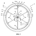
図1は本開示の一実施形態にしたがう自転車車輪10の斜視部分分解組立図であり、図2は車輪10の側面図である。基準系を確立する目的のため、車輪10は中心回転軸12に関して回転可能であり、中心軸に対して垂直な縦中心面14に関して概ね対称である。図2に示される車輪10の実施形態を見る場合、縦中心面14は紙面に平行であり、中心軸12は紙面に垂直に内外に延びる。
FIG. 1 is a perspective partially exploded view of a
図示される実施形態の車輪10は、中心軸12と同軸に位置合わせされ、縦中心面14に概ね対称である、環形リム16を有する。リム16は縦中心面の両側に配置された第1の側面18及び第2の側面20を有する。図1に示されるように、第1の側面18は左側面であり、第2の側面20は右側面である。本明細書において語「左」及び「右」は、図に示される図面に関する実施形態を説明するための空間基準の目的のために用いられることは当然である。リム16はクリンチャー式リムとすることができ、別の実施形態において、リムはチューブ式またはソーアップ式のリムとすることができる。リム16は、炭素繊維材料またはその他の適するファイバ素材材料のような、ファイバ素材材料で作製することができる。別の実施形態において、リムは、アルミニウム、アルミニウム合金またはその他の適する金属のような、金属材料で作製することができる。また別の実施形態において、リム16は、高性能車輪アセンブリのような、車輪に用いるに適する強度及び耐久特性を有する、他の材料で作製することができる。
The
車輪10は、縦中心面14の両側にそれぞれ配置された、一体左側面素子22及び一体右側面素子24を有する。一体側面素子は、(炭素繊維材料またはその他の複合繊維材料を含む)ファイバ素材材料、耐久性プラスチック、金属または、使用中に車輪に印加される力に耐え得るに十分に強く、耐久性がある、その他の材料で作製することができる。左側面素子22はリムの左側面18に固定結合され、右側面素子24はリムの右側面20に固定結合される。側面素子22及び24はリム16の側面18及び20に、接合、接着、(超音波溶接、摩擦圧接、誘導溶接、等を含む)溶接、または溶着することができ、あるいは他の手段で確実に結合させることができる。図示される実施形態において、左側面素子22及び右側面素子24は実質的に同じ構成を有する。左側面素子22及び右側面素子24はそれぞれ、外端部32において環形槽壁34にそれぞれが一体連結された複数本のスポーク30を有する、一個構成の一体構造である。スポーク30はそれぞれ、内端部36において、中心軸12に関して同軸配置された中心フランジ部38に一体連結される。フランジ部38は、車輪10がそれに関して回転する車軸構造を受け入れるように構成された中心ハブ40に、接合、接着、(超音波溶接、摩擦圧接、誘導溶接、等を含む)溶接、または溶着することができ、あるいは他の手段で確実に結合させることができる。
The
図示される実施形態のハブ40は、端部が縦中心面14の両側にある、管状部材であり、ハブはリムに対して同軸に位置合わせされ、同心配置される。したがって、一体側面素子22及び24はリム16とハブ40の間に広がり、リム16及びハブ40を構造的に相互連結する。図示される実施形態は自転車の前輪のためのフランジを示すが、同じ構成を後輪に対しても、中心フランジの形状が後輪用のハブ40,車軸及びギアを受け入れるに適していることを除いて、用いることができる。
The
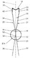
図3及び4に見られるように、左側面素子22の環形側壁34はリムの左側面18に確実に固定された、径方向に外側の係合部42を有する。左側壁34は径方向に内側に、縦中心面14に向かって延びて、径方向に内側の端部44において終端する。右側面素子24の環形側壁34は、径方向に外側の係合部46がリムの右側面20に確実に固定されている、同様の構成を有する。右側壁34は径方向に内側に、縦中心面14に向かって延びて、左側壁34の内端部44に直に隣接する、径方向に内側の端部48において終端する。したがって、左側及び右側の側壁34はリム16から離れる方向に広がり、互いに向けて収斂して、側壁34間に楔形空間50を定める。
As can be seen in FIGS. 3 and 4, the
図示される実施形態において、側壁34の左内端部44及び右内端部48は、リム16から内向きの側壁34間の楔形空間50が完全に封止されるように相互に、接合、接着、(超音波溶接、摩擦圧接、誘導溶接、等を含む)溶接または溶着されるか、あるいは他の手段で確実に結合される、係合部を実質的に縦中心面14に定める。図示される実施形態では側壁を相互に、及びリムに、接合するために接着剤を用いているが、他の実施形態では側壁34をリム16に結合するに適する他の手法または機構を用いることができる。
In the illustrated embodiment, the left
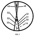
図1及び2に示されるように、左側面素子22及び右側面素子24のそれぞれは、車輪10にわたって均等に分配された6本のスポーク30を有する。別の実施形態において、側面素子22及び24は6本より多いかまたは少ないスポーク30を有することができる。左側面素子22及び右側面素子24は、一方の側面素子に2本または4本のスポーク及び他方の側面素子に6本または8本のスポークのように、異なる数のスポークを有することができる、図示される実施形態において、左側面素子22のそれぞれのスポーク30は、右側素子24の対応するスポーク30と位置合わせされて、縦中心面14の両側で位置合わせされた複合ファイバスポーク30の対31を定める。
As shown in FIGS. 1 and 2, each of the
図3及び5に見られるように、左側面素子22のそれぞれのスポーク30の外端部32は左側壁34の内端部44と一体連結される。同様に、右側面素子24のそれぞれのスポーク30の外端部32は右側壁34の内端部48と一体連結される。少なくとも1つの実施形態において、側面素子22及び24は、炭素繊維ユニットまたはその他の複合繊維ユニットのような、一体ファイバ素材側面素子である。側壁34とスポーク30の間の一体連結は、側壁34の部分と対応するスポーク30の外端部32を形成する、炭素繊維布のような、連続複合ファイバ材料の1つ以上の層を有する。したがって、連続ファイバは側壁34の部分とスポーク30にかけて広がってこれらの一体連結部品管の極めて強固な相互連結を提供する。
As can be seen in FIGS. 3 and 5, the
図示される実施形態において、左及び右の側壁34の内端部44及び48は相互に連結され、左及び右の側壁34のそれぞれに連結された、スポーク30の位置合わせされた対31のそれぞれも、位置合わせされたスポーク30の外端部32が互いに直に隣接するように収斂する。少なくとも1つの実施形態において、スポーク30のそれぞれの対31の外端部32は実質的に縦中心面14において相互に連結される。しかし、左側面素子22のスポーク30は左側壁34に一体連結されて縦中心面14の右側には交わらないことに注意されたい。同様に、右側面素子24のスポーク30は左側壁34に一体連結されて縦中心面14の左側には交わらない
少なくとも1つの実施形態の車輪10は、左及び右の側壁34に隣接し、車輪10の使用中のスポークの外端部32(及び対応する側壁34の内端部44/48)の縦中心面14に対して垂直な方向での相互の離反を防止するか、そうではなくとも対抗するため、位置合わせされたスポーク30のそれぞれの対31の外端部32を結束するように配置された、結束部材52を有する。結束部材32は側壁34の直に隣接して位置合わせされたスポーク30の外端部30の周囲に巻き付くラッシング部材とすることができる。結束部材32は、スポーク30を囲んで巻き付けられ、所定の場所で硬化された、炭素繊維材料のような、複合ファイバ材料とすることができる。別の実施形態において、結束部材52は、スポーク30または側壁34に固定態様で取り付いてスポーク及び側壁の分離を防止する、クリップまたはその他の機械器具とすることができる。
In the illustrated embodiment, the inner ends 44 and 48 of the left and
図6はスポーク30と左側面素子22及び右側面素子24のそれぞれの中心フランジ38の間の一体連結を示す断面図である。一体ファイバ素材側面素子22及び24を含む実施形態において、スポーク30は、スポーク30の内端部30及び中心フランジ38の部分を形成する、炭素繊維布のような、連続複合繊維材料の1つ以上の層によってそれぞれの中心フランジ38に一体連結される。したがって、連続ファイバはそれぞれのスポーク30及び中心フランジ38にかけて広がり、これらの一体連結された部品間の極めて強固な相互連結を提供する。少なくとも1つの実施形態において、複合繊維材料の1つ以上の層は、左側面素子22または右側面素子24のそれぞれの、スポーク30、中心フランジ38及び側壁34の部分を形成する。したがって、連続ファイバは、スポークの全長にかけて、及びフランジ及び側壁の隣接部分に沿って、広がる。フランジ、スポーク及び側壁の構成にかけて完全に広がる、連続ファイバのこの構成はこれらの一体連結された部品間の極めて強固な相互連結を提供し、同時に車輪10の重量を最小限に抑える。
FIG. 6 is a cross-sectional view showing the integral connection between the
図6に見られるように、それぞれの中心フランジ38の径方向に内側の部分54はハブ40の外端部56に連結される。図示される実施形態において、中心フランジ38は中心軸12と同軸で位置合わせされた開口58を有し、開口58はハブ40の内径に実質的に対応する直径を有する、開口58の周りの中心フランジ38がキャップ60のヘッド62とハブ40の間に堅く押さえ込まれるように、キャップ60が開口58を通してハブ40内にまたはハブ40に対してある程度延び込む。図示される実施形態において、キャップ60は圧迫状態でハブ40も押さえ込み、これは車輪10に静的張力を維持する。キャップ60は、左側面素子22及び右側面素子24の中心フランジ38がハブ40の末端において縦中心面14の両側で互いに隔てられて支持されるように、中心フランジ38及び/またはハブ40の外端部56に接着される。ハブ40,隔てられた中心フランジ38及び、それぞれが外端部32においてそれぞれの相手のスポーク30に結束された、一体連結されたスポーク30のこの構成の結果、車輪10にわたるスポーク30は一様な張力で保持される。図示される実施形態のキャップ60は回転軸と同軸で配置された内部ベアリングを有し、ベアリングは回転軸の周りの円滑な回転のために車軸を支持する。他の実施形態において、キャップ60は、例えば、外部または内部のギア装置、外付(ディスク)または内蔵(ドラム)のブレーキ装置、パワーメーター、電気モーター、発電機、電池または、自転車に乗るときに使用できる、その他の適する部品を支持するための、構造も有することができる。
As seen in FIG. 6, the radially inner portion 54 of each
キャップ60は、自転車に連結するために所定の位置でハブ40に車軸アセンブリを配置することを可能にするように構成された、環形部材である。キャップ60は、側面素子22及び24のそれぞれの中心フランジ32に取り付けられる、炭素繊維材料または複合繊維材料とすることができる。別の実施形態において、キャップ60は、アルミニウム合金のような、金属、あるいは、中心フランジ38及び/またはハブ40に固定態様で結合させるか、そうではなくとも確実に取り付けることができる、その他の適する金属材料とすることができる。
The
車輪10の左側面素子22及び右側面素子24は、リム16及びハブ40にユニットとして取り付けることができる、概ねフラットな、一個構成の一体部材として構成することができる。例えば、側面素子が一体炭素繊維側面素子である少なくとも1つの実施形態において、左側面素子22及び右側面素子24のそれぞれは、側壁34,スポーク30及び中心フランジ38を定めるための形状につくられて配位された、炭素繊維布材料の複数の層を積み重ねることによって形成される。この炭素繊維層構造の全体はジグ内に概ねフラットな位置でユニットとして配置され、熱及び圧力を用いて硬化される。一実施形態において、複数の選ばれた形状の炭素繊維布片が、少なくとも1つの連続布片がそれぞれのスポーク30と側壁34の隣接部の間の一体インターフェースを形成するために配置されるように、積み重ねられる。選ばれた形状の連続ファイバ素材布片を、スポーク全体並びに対応する側壁34及び中心フランジ34のそれぞれの部分に沿って広がる層を形成するための形状寸法につくることができる。この構成において、概ね径方向に配位された連続ファイバが、フランジ、スポーク30の全体及び側壁34にかけて広がることができる。
The
側面素子22及び24が冷却されて、ジグから取り出された後、側面素子22及び24は比較的フラットであり、スポーク30にはまだ張力がかかっていない。側面素子22及び24は次いでリム16の左側面18及び右側面20にそれぞれ接合されるか、そうではなくとも取り付けられ、スポーク30の外端部32が結束部材によって結束される。中心フランジが相互に隔てられて保持されるように、ハブ40がハブの外端部56において中心フランジ間に配置され、中心フランジをハブ70に対して押さえ込むためにキャップ60が所定の場所に固定される。中心フランジ38が相互に引き離されてハブ40及び/またはキャップ60の外端に固定されると、スポーク30は車輪10にわたって一様に張力がかけられて、スポーク30は引張状態に維持される。側面素子22及び24並びにその他の部品が接合または接着されるか、または別の手段で合わせて固定された後に得られた車輪10は、非常に強く、軽量で、耐久性があり、バランスがとられていて、自転車及び自転車乗りに極めて円滑な乗り心地を提供する、正しく調整された車輪である。
After the
側面素子22及び24のこの構成によって、部品の完全な積重ね及び単一工程での硬化が可能になり、この結果、一体形成部分の精確な位置合わせが得られる。この構成によって、スポークと側壁及び/または中心フランジの間の、多数の個別重ね継ぎも排除される。この構成によって、費用または時間がそれほどかからない態様で作製することができる一層強健な車輪を提供する、一体連結部品にわたる構造健全性も与えられる。
This configuration of
上述から、本発明の特定の実施形態は例証の目的のために本明細書に説明されているが、本発明を逸脱することなく様々な改変がなされ得ることは当然であろう。さらに、特定の実施形態または実施例に関連して説明した本発明の態様が、別の実施形態においては組み合わされるかまたは排除され得る。本発明のいくつかの実施形態にともなう利点をそれらの実施形態に関連して説明したが、他の実施形態もそのような利点を示すことがあり得る。さらに、必ずしも全ての実施形態が本発明の範囲内に入るためにそのような利点を有する必要はない。したがって、本発明は添付される特許請求の範囲による以外に限定されることはない。 From the foregoing, it will be appreciated that while specific embodiments of the invention have been described herein for purposes of illustration, various modifications may be made without departing from the invention. Furthermore, aspects of the invention described in connection with particular embodiments or examples may be combined or eliminated in other embodiments. Although the advantages associated with some embodiments of the invention have been described in connection with those embodiments, other embodiments may exhibit such advantages. Moreover, not all embodiments need have such advantages in order to fall within the scope of the invention. Accordingly, the invention is not limited except as by the appended claims.
10 自転車車輪
12 中心回転軸
14 縦中心面
16 環形リム
18,20 リム側面
22,24 側面素子
30 スポーク
31 ファイバスポーク対
32 スポーク外端部
34 環形側壁
36 スポーク内端部
38 中心フランジ部
40 中心ハブ
42,46 係合部
44,48 側壁内端部
50 楔形空間
52 結束部材
54 中心フランジ径方向内側部
56 ハブ外端部
58 開口
60 キャップ
62 キャップヘッド
DESCRIPTION OF
Claims (32)
前記縦中心面の両側に第1の側面及び第2の側面をもつリム、
前記縦中心面の両側にあって、前記リムに対し、軸方向に位置合わせされ、同心に配置されている、第1の端部及び第2の端部を有するハブ、及び
前記縦中心面の両側に配置され、前記リム及び前記ハブに結合されている、一対の一体側面素子、
−前記側面素子のそれぞれは、環形側壁、フランジ部及び、前記環形側壁と前記フランジ部を一体相互連結する、複数本のスポークを有する、
−前記側面素子は第1の側面素子及び第2の側面素子を含む、
−前記第1の側面素子の前記環形側壁は前記リムの前記第1の側面に固定され、前記第1の側面素子の前記フランジ部は前記ハブの前記第1の端部に固定される、
−前記第2の側面素子の前記環形側壁は前記リムの前記第2の側面に固定され、前記第2の側面素子の前記フランジ部は前記ハブの前記第2の端部に固定される、
−前記第1の側面素子及び前記第2の側面素子の前記複数本のスポークは前記第1の側面素子及び前記第2の側面素子のそれぞれの前記側壁と前記フランジの間で引張状態にある、
を有し、
前記第1の側面素子の前記スポークが前記第2の側面素子の前記複数本のスポークと位置合わせされて配置され、前記第1の側面素子及び前記第2の側面素子の前記複数本のスポークのそれぞれが前記側壁に隣接する端部を有し、前記第1の側面素子の前記複数本のスポークのそれぞれの前記端部が前記第2の側面素子の位置合わせされたスポークの前記端部に結束されて、前記結束された端部の前記縦中心面に対して垂直な方向での相互に離反する動きを制限する、
ことを特徴とする車輪。 In a bicycle wheel having a longitudinal center plane perpendicular to the rotation axis,
A rim having a first side and a second side on both sides of the longitudinal center plane;
A hub having a first end and a second end that are axially aligned and concentrically with respect to the rim on both sides of the longitudinal center plane; and A pair of integral side elements disposed on both sides and coupled to the rim and the hub;
Each of the side elements has an annular sidewall, a flange portion, and a plurality of spokes interconnecting the annular sidewall and the flange portion together;
The side element comprises a first side element and a second side element;
The annular side wall of the first side element is fixed to the first side of the rim, and the flange part of the first side element is fixed to the first end of the hub;
The annular side wall of the second side element is fixed to the second side of the rim, and the flange part of the second side element is fixed to the second end of the hub;
The plurality of spokes of the first side element and the second side element are in tension between the respective side walls of the first side element and the second side element and the flange;
Have
The spokes of the first side element are arranged in alignment with the plurality of spokes of the second side element, and the plurality of spokes of the first side element and the second side element are arranged. Each has an end adjacent to the side wall, and each end of the plurality of spokes of the first side element is bound to the end of the aligned spoke of the second side element The movement of the bound ends in a direction perpendicular to the longitudinal center plane is limited.
A wheel characterized by that.
前記縦中心面の両側に第1の側面及び第2の側面をもつリム、
前記縦中心面の両側にあって、前記リムに対し、軸方向に位置合わせされ、同心に配置されている、第1の端部及び第2の端部を有するハブ、及び
前記縦中心面の両側に配置され、前記リム及び前記ハブに結合されている、一対の一体側面素子、
−前記側面素子のそれぞれは、環形側壁、フランジ部及び複数本のスポークを有し、前記複数本のスポークは、前記環形側壁と前記フランジ部を、前記環形側壁と前記スポークの間に広がる第1の連続ファイバによって、及び前記スポークと前記フランジ部の間に広がる第2の連続ファイバによって、一体相互連結する、
を有し、
前記側面素子が第1の側面素子及び第2の側面素子を含み、前記第1の側面素子の前記環形側壁が前記リムの前記第1の側面に固定され、前記第1の側面素子の前記フランジ部が前記ハブの前記第1の端部に固定され、前記第2の側面素子の前記環形側壁が前記リムの前記第2の側面に固定され、前記第2の側面素子の前記フランジ部が前記ハブの前記第2の端部に固定され、前記第1の側面素子及び前記第2の側面素子の前記複数本のスポークが前記第1の側面素子及び前記第2の側面素子のそれぞれの前記側壁と前記フランジの間で引張状態にある、
ことを特徴とする車輪。 In a bicycle wheel having a longitudinal center plane perpendicular to the rotation axis,
A rim having a first side and a second side on both sides of the longitudinal center plane;
A hub having a first end and a second end that are axially aligned and concentrically with respect to the rim on both sides of the longitudinal center plane; and A pair of integral side elements disposed on both sides and coupled to the rim and the hub;
Each of the side elements has an annular side wall, a flange portion and a plurality of spokes, the plurality of spokes extending through the annular side wall and the flange portion between the annular side wall and the spoke; Integrally interconnected by a continuous fiber and by a second continuous fiber extending between the spoke and the flange portion;
Have
The side element includes a first side element and a second side element, the annular side wall of the first side element is fixed to the first side surface of the rim, and the flange of the first side element A portion is fixed to the first end of the hub, the annular side wall of the second side element is fixed to the second side of the rim, and the flange portion of the second side element is the The plurality of spokes of the first side element and the second side element are fixed to the second end of the hub, and the side walls of the first side element and the second side element respectively. And in tension between the flange and
A wheel characterized by that.
前記側面素子のそれぞれが、環形側壁、フランジ部及び、前記環形側壁と前記フランジ部を一体相互連結する、複数本のスポークを有する一体部材であり、
前記環形側壁のそれぞれが前記リムに固定態様で連結するように構成され、前記フランジ部のそれぞれが前記ハブに固定態様で連結するように構成され、前記環形側壁のいずれの一方も他方の前記環形側壁の径方向に内側の端部に確実に取り付けられるように構成された径方向に内側の端部を有し、前記第1の側面素子及び前記第2の側面素子の前記複数本のスポークが前記側壁と前記フランジの間で引張状態にあるように構成され、前記側面素子のそれぞれが、前記スポークが引張状態にあるときには、前記縦中心面の他方の側に交わることなく、前記縦中心面の両側にあるように構成され、
前記側面素子のそれぞれからの前記スポークの端部が前記側壁に隣接して互いに結束されて、前記縦中心面に対して垂直な方向での相互に離反する動きを制限する、
ことを特徴とする一対の一体側面素子。 In a pair of integral side elements for use in a bicycle wheel having a rim, a hub and a longitudinal center plane,
Each of the side elements is an integral member having an annular sidewall, a flange portion, and a plurality of spokes integrally interconnecting the annular sidewall and the flange portion;
Each of the annular side walls is configured to be coupled to the rim in a fixed manner, and each of the flange portions is configured to be coupled to the hub in a fixed manner, and any one of the annular side walls is configured to be the other annular shape. A plurality of spokes of the first side surface element and the second side surface element having a radially inner end portion configured to be securely attached to a radially inner end portion of the side wall; The longitudinal center plane is configured to be in a tension state between the side wall and the flange, and each of the side surface elements does not intersect the other side of the longitudinal center plane when the spoke is in a tension state. Configured to be on both sides of the
The ends of the spokes from each of the side elements are bound together adjacent to the side wall to limit the movement away from each other in a direction perpendicular to the longitudinal center plane;
A pair of integral side elements.
前記側面素子のそれぞれが、環形側壁、フランジ部及び、前記環形側壁と前記フランジ部を、前記環形側壁と前記スポークの間に広がる第1の連続ファイバによって、及び前記スポークと前記フランジ部の間に広がる第2の連続ファイバによって、一体相互連結する、複数本のスポークを有する一体部材であり、
前記環形側壁のそれぞれが前記リムに固定態様で連結するように構成され、前記フランジ部のそれぞれが前記ハブに固定態様で連結するように構成され、第1の前記側面素子及び第2の前記側面素子の前記複数本のスポークが前記側壁と前記フランジの間で引張状態にあるように構成され、前記側面素子のそれぞれが、前記スポークが引張状態にあるときには、前記縦中心面の他方の側に交わることなく、前記縦中心面の両側にあるように構成される、
ことを特徴とする側面素子。 In a pair of fiber material side elements for use in a bicycle wheel having a rim, hub and longitudinal center plane,
Each of the side elements includes an annular sidewall, a flange portion, and the annular sidewall and the flange portion by a first continuous fiber extending between the annular sidewall and the spoke, and between the spoke and the flange portion. An integral member having a plurality of spokes interconnected integrally by a second continuous fiber that spreads;
Each of the annular side walls is configured to be connected to the rim in a fixed manner, and each of the flange portions is configured to be connected to the hub in a fixed manner, and the first side surface element and the second side surface are configured. The plurality of spokes of the element are configured to be in tension between the side wall and the flange, and each of the side elements is on the other side of the longitudinal center plane when the spoke is in tension. Configured to be on both sides of the longitudinal center plane without intersecting,
A side element characterized by that.
第1の側面及び第2の側面をもつリム、
−前記リムは実質的に円形であり、中心軸を囲んで配置される、及び
−前記第1の側面は前記縦中心面の第1の側に配置され、前記第2の側面は前記縦中心面の第1の側とは反対側の第2の側に配置される、
前記中心軸と位置合わせされ、前記リムの径方向に内側に配置された、第1の端部及び第2の端部を有するハブ管、
前記リム及び前記ハブ管に結合された第1の側の一体側面素子、
−前記第1の側の側面素子は前記縦中心面の前記第1の側に配置される、
−前記第1の側の側面素子は、前記リムの前記第1の側面に固定された第1の側壁、前記ハブ管の前記第1の端部に結合された第1の中心フランジ部及び、第1の端部において前記第1の側壁に一体連結され、第2の端部において前記第1の中心フランジ部に一体連結された、複数本の第1のスポークを有する、
−前記第1のスポークは前記縦中心面の前記第1の側に配され、前記縦中心面の前記第1の側で前記第1の側壁に連結される、
−前記第1の側壁、
及び
前記リム及び前記ハブ管に結合された第2の側の一体側面素子、
−前記第2の側の側面素子は前記縦中心面の前記第2の側に配置される、
−前記第2の側の側面素子は、前記リムの前記第2の側面に固定された第2の側壁、前記ハブ管の前記第2の端部に結合された第2の中心フランジ部及び、第1の端部において前記第2の側壁に一体連結され、第2の端部において前記第2の中心フランジ部に一体連結された、複数本の第2のスポークを有する、
−前記第2のスポークは前記縦中心面の前記第2の側に配され、前記縦中心面の前記第2の側で前記第2の側壁に連結される、
−前記第2の側壁、
を有し、
前記第1のスポークが前記第1の側壁と前記第1の中心フランジの間に引張状態で保持され、前記第2のスポークが前記第2の側壁と前記第2の中心フランジの間に引張状態で保持される、及び
前記第1のスポークのそれぞれが前記第2のスポークのそれぞれ1本と位置合わせされて、前記縦中心面の両側で位置合わせされたスポークの対を形成し、前記位置合わせされたスポークの対の前記第1のスポーク及び前記第2のスポークのそれぞれの前記第1の端部が、前記位置合わせされたスポークの対の前記第1の端部の前記縦中心面に対して垂直な方向での相互に離反する動きを制限する結束部材によって結束される、
ことを特徴とする車輪。 A wheel that is rotatable about a central axis and has a longitudinal central plane perpendicular to the central axis, the wheel comprising:
A rim having a first side and a second side;
The rim is substantially circular and is disposed around a central axis; and the first side is disposed on a first side of the longitudinal center plane and the second side is the longitudinal center. Disposed on a second side opposite the first side of the surface;
A hub tube having a first end and a second end, aligned with the central axis and disposed radially inward of the rim;
A first side integral side element coupled to the rim and the hub tube;
The first side surface element is disposed on the first side of the longitudinal center plane;
The first side surface element comprises a first side wall fixed to the first side surface of the rim, a first central flange portion coupled to the first end of the hub tube; and A plurality of first spokes integrally connected to the first side wall at a first end and integrally connected to the first central flange at a second end;
The first spoke is disposed on the first side of the longitudinal center plane and connected to the first side wall on the first side of the longitudinal center plane;
The first side wall;
And a second side integral side element coupled to the rim and the hub tube;
The second side surface element is disposed on the second side of the longitudinal center plane;
The second side surface element comprises a second sidewall fixed to the second side surface of the rim, a second central flange portion coupled to the second end of the hub tube; A plurality of second spokes integrally connected to the second side wall at a first end and integrally connected to the second center flange at a second end;
The second spoke is disposed on the second side of the longitudinal center plane and connected to the second side wall on the second side of the longitudinal center plane;
-Said second sidewall,
Have
The first spoke is held in tension between the first side wall and the first center flange, and the second spoke is in tension between the second side wall and the second center flange. And each of the first spokes is aligned with a respective one of the second spokes to form a pair of spokes aligned on opposite sides of the longitudinal center plane, the alignment The first end of each of the first spoke and the second spoke of the aligned spoke pair is relative to the longitudinal center plane of the first end of the aligned spoke pair Bound by a binding member that restricts the movement away from each other in the vertical direction,
A wheel characterized by that.
第1のフランジ部、第1の外側係合部及び第1の内側係合部をもつ第1の環形側壁及び、前記縦中心面の第1の側に配されて前記第1の環形側壁と前記第1のフランジ部を一体相互連結している、第1のスポークを有する前記第1の一体側面素子と、第2のフランジ部、第2の外側係合部及び第2の内側係合部をもつ第2の環形側壁及び、前記縦中心面の第2の側に配されて前記第2の環形側壁と前記第2のフランジ部を一体相互連結している、第2のスポークを有する前記第2の一体側面素子を前記リムに取り付ける工程であって、前記第1の外側係合部は前記縦中心面の前記第1の側で前記リムの第1の側面に取り付けられ、前記第2の外側係合部は前記縦中心面の前記第2の側で前記リムの第2の側面に取り付けられる工程、
前記第1の側壁の前記第1の内側係合部を前記第2の側壁の前記第2の内側係合部に固定する工程、
前記第1のフランジ部を前記縦中心面の前記第1の側で前記ハブの第1の端部に取り付ける工程、
前記第2のフランジ部を前記縦中心面の前記第2の側で前記ハブの第2の端部に取り付ける工程であって、前記第1のフランジ部及び前記第2のフランジを前記縦中心面から引き離すことで、前記第1のスポークは前記第1の側壁と前記第1のフランジ部の間で引張状態に保持され、前記第2のスポークは前記第2の側壁と前記第2のフランジ部の間で引張状態に保持される工程、
及び
前記第1のスポークのそれぞれの径方向外端部を前記第2のスポークの位置合わせされたそれぞれの位置合わせされた径方向端部を、位置合わせされたスポークの対を定めて、前記位置合わせされたスポークの対の前記径方向外端部の前記縦中心面に対して垂直な方向での相互に離反する動きを制限するため、結束部材で結束する工程、
を含むことを特徴とする方法。 In a method of manufacturing a bicycle wheel having a rim, a hub, and a pair of opposed first and second integrated side surface elements, the wheel has a rotation axis and a vertical center plane perpendicular to the rotation axis. The method comprises:
A first annular sidewall having a first flange portion, a first outer engagement portion and a first inner engagement portion; and the first annular sidewall disposed on a first side of the longitudinal center plane; The first integral side surface element having a first spoke, the second flange portion, the second outer engagement portion, and the second inner engagement portion integrally interconnecting the first flange portion. And a second spoke having a second annular side wall and a second spoke disposed on the second side of the longitudinal center plane and integrally interconnecting the second annular side wall and the second flange portion. Attaching a second integral side element to the rim, wherein the first outer engagement portion is attached to the first side of the rim on the first side of the longitudinal center plane; An outer engaging portion of the rim being attached to the second side of the rim on the second side of the longitudinal center plane;
Fixing the first inner engagement portion of the first side wall to the second inner engagement portion of the second side wall;
Attaching the first flange to the first end of the hub on the first side of the longitudinal center plane;
Attaching the second flange portion to the second end of the hub on the second side of the longitudinal center plane, wherein the first flange portion and the second flange are attached to the longitudinal center plane; The first spoke is held in tension between the first side wall and the first flange portion, and the second spoke is the second side wall and the second flange portion. A process of being held in tension between
And each radial outer end of the first spoke is aligned with each aligned radial end of the second spoke and a pair of aligned spokes is defined, A step of bundling with a bundling member in order to limit the mutually separated movement in a direction perpendicular to the longitudinal center plane of the radially outer end of the pair of aligned spokes;
A method comprising the steps of:
それぞれが環形側壁、前記側壁の径方向に内側の中心フランジ部及び、前記側壁と前記中心フランジの間に延びる、複数本のスポークを有する、第1の一体ファイバ素材側面素子及び第2の一体ファイバ素材側面素子を形成する工程であって、前記側面素子のそれぞれは、前記側壁、前記中心フランジ及び前記スポークを、前記フランジと前記スポークの間に広がる少なくとも第1の連続ファイバ及び前記スポークと前記中心フランジの間に広がる少なくとも第2の連続ファイバによって、形成するための形状につくられた複数枚のファイバ素材材料シートを積み重ねるステップ及び、前記スポークが前記側壁及び前記フランジに一体連結されている硬化された側面素子を形成するため、前記側面素子の全体を一硬化プロセスにおいて熱及び圧力によって硬化するステップによって、形成されるものである工程、
前記第1の側面素子と前記第2の側面素子を、リムに隣接させ、スポークを相互に位置合わせして、位置決めする工程、
前記第1の側面素子及び前記第2の側面素子の前記側壁をリムの両側面に取り付ける工程、
前記第1の側面素子及び前記第2の側面素子をハブに配置する工程及び前記第1の側面素子及び前記第2の側面素子を前記スポークが引張状態にあるように配置する工程、及び
前記第1の側面素子及び前記第2の側面素子の前記フランジを前記ハブに固定する工程、
を含むことを特徴とする方法。 In a method of making a fiber material wheel for a bicycle,
A first integrated fiber material side surface element and a second integrated fiber, each having an annular side wall, a central flange portion radially inward of the side wall, and a plurality of spokes extending between the side wall and the central flange Forming a side surface element, wherein each of the side elements includes at least a first continuous fiber and the spoke and the center extending from the side wall, the central flange and the spoke between the flange and the spoke. Stacking a plurality of fiber stock sheets shaped to form with at least a second continuous fiber extending between the flanges, and curing the spokes integrally connected to the sidewalls and the flanges. In order to form a side element, the entire side element is heated in one curing process. Step those by the step of curing, which is formed by the force,
Positioning the first side element and the second side element adjacent to a rim and aligning the spokes with each other;
Attaching the side walls of the first side element and the second side element to both side faces of the rim;
Disposing the first side element and the second side element on a hub, disposing the first side element and the second side element such that the spokes are in tension; and Fixing the flanges of the first side element and the second side element to the hub;
A method comprising the steps of:
Applications Claiming Priority (3)
| Application Number | Priority Date | Filing Date | Title |
|---|---|---|---|
| US13/535,290 | 2012-06-27 | ||
| US13/535,290 US9108461B2 (en) | 2012-06-27 | 2012-06-27 | Bicycle wheel with unitary side construction |
| PCT/US2013/047985 WO2014004727A1 (en) | 2012-06-27 | 2013-06-26 | Bicycle wheel with unitary side construction |
Publications (2)
| Publication Number | Publication Date |
|---|---|
| JP2015521973A true JP2015521973A (en) | 2015-08-03 |
| JP2015521973A5 JP2015521973A5 (en) | 2016-08-18 |
Family
ID=49777344
Family Applications (1)
| Application Number | Title | Priority Date | Filing Date |
|---|---|---|---|
| JP2015520475A Pending JP2015521973A (en) | 2012-06-27 | 2013-06-26 | Side integrated bicycle wheel |
Country Status (10)
| Country | Link |
|---|---|
| US (2) | US9108461B2 (en) |
| EP (1) | EP2867032A4 (en) |
| JP (1) | JP2015521973A (en) |
| KR (1) | KR20150027250A (en) |
| CN (1) | CN104968509B (en) |
| AU (1) | AU2013280303A1 (en) |
| CA (1) | CA2877939A1 (en) |
| MX (1) | MX2015000154A (en) |
| TW (1) | TWI631024B (en) |
| WO (1) | WO2014004727A1 (en) |
Families Citing this family (9)
| Publication number | Priority date | Publication date | Assignee | Title |
|---|---|---|---|---|
| US9108461B2 (en) * | 2012-06-27 | 2015-08-18 | Cayucos Cowboys, Llc | Bicycle wheel with unitary side construction |
| DE102013201842A1 (en) * | 2013-02-05 | 2014-08-21 | ThyssenKrupp Carbon Components GmbH | Radstern made of composite spoke elements and its connection to the rim base |
| US9403404B2 (en) * | 2014-01-28 | 2016-08-02 | Po-Chien Lin | Carbon fiber rim and method of manufacturing the same |
| ITUA20161779A1 (en) * | 2016-03-17 | 2017-09-17 | Campagnolo Srl | Bicycle wheel and related manufacturing process |
| KR102487167B1 (en) * | 2016-12-14 | 2023-01-10 | 현대자동차 주식회사 | Bicycle wheel and manufacturing the same |
| WO2019033175A1 (en) * | 2017-08-18 | 2019-02-21 | Carbon Revolution Limited | Shaped preform for spoke portion of a composite wheel |
| FR3084286B1 (en) * | 2018-07-26 | 2021-02-26 | H Prec | WHEEL SAIL AND MANUFACTURING MACHINE |
| CN114746283A (en) * | 2019-09-30 | 2022-07-12 | Css复合材料有限责任公司 | Reinforced thermoplastic parts and method of making same |
| US11660909B2 (en) | 2019-12-11 | 2023-05-30 | Sram, Llc | Tire retaining feature for a bicycle rim |
Citations (6)
| Publication number | Priority date | Publication date | Assignee | Title |
|---|---|---|---|---|
| FR406445A (en) * | 1909-08-24 | 1910-01-29 | Louis Bled | Manufacturing process for vehicle wheels |
| FR708138A (en) * | 1930-12-19 | 1931-07-20 | Manuf Fr D Ameublement De Jeux | Wheel for children's car and toys |
| JPS5932501A (en) * | 1982-08-17 | 1984-02-22 | Honda Motor Co Ltd | Frp spoke plate |
| JPH07505349A (en) * | 1990-10-26 | 1995-06-15 | シュランガー ラファエル | Wheel |
| JPH0999702A (en) * | 1995-10-04 | 1997-04-15 | Araya Kogyo Kk | Wheel for bicycle and its manufacture |
| US20080265659A1 (en) * | 2007-04-24 | 2008-10-30 | Joachim Heyse | Spoke, wheel and process for manufacturing a spoke, especially for bicycles |
Family Cites Families (51)
| Publication number | Priority date | Publication date | Assignee | Title |
|---|---|---|---|---|
| US3369843A (en) | 1965-07-16 | 1968-02-20 | Philip E. Prew | Laminated wheel and method of manufacture |
| DE2026837A1 (en) | 1970-06-02 | 1971-12-30 | Fichtel & Sachs Ag, 8720 Schweinfurt | Vehicle wheel made of plastic with a brake hub and tools for its manufacture |
| US3862779A (en) | 1973-05-01 | 1975-01-28 | William Weir Jayne | Vehicle wheel |
| US4280736A (en) | 1979-05-24 | 1981-07-28 | Raudman Charles J | Vehicle wheel |
| FR2460195A1 (en) | 1979-07-02 | 1981-01-23 | Ferrary J P | METHOD FOR MANUFACTURING CYCLE RIM OR CYCLOMOTOR RIM |
| DE3134249A1 (en) | 1981-08-29 | 1983-03-17 | Bayer Ag, 5090 Leverkusen | PLASTIC WHEEL |
| US4413860A (en) | 1981-10-26 | 1983-11-08 | Great Lakes Carbon Corporation | Composite disc |
| US4532097A (en) | 1981-12-28 | 1985-07-30 | Ford Motor Company | Method of forming fiber reinforced synthetic material wheel |
| JPS58118401A (en) | 1982-01-07 | 1983-07-14 | Honda Motor Co Ltd | Production method of rim made of continuous fiber reinforced plastic |
| JPS58118402A (en) | 1982-01-07 | 1983-07-14 | Honda Motor Co Ltd | Spoke plate made of carbon fiber reinforced plastic |
| US4527839A (en) | 1982-04-30 | 1985-07-09 | Honda Giken Kogyo Kabushiki Kaisha | Synthetic wheel formed from two halves |
| US4793659A (en) | 1982-11-30 | 1988-12-27 | Werner Oleff | Spoked wheel of synthetic material and method of making therefor |
| DE3345555C2 (en) | 1983-12-16 | 1986-10-02 | Messerschmitt-Bölkow-Blohm GmbH, 8012 Ottobrunn | Disc wheel |
| DE3722307A1 (en) | 1987-07-06 | 1989-01-26 | Anatolij Sergeevic Cygankov | WHEEL FOR A BICYCLE |
| US4919490A (en) | 1988-10-12 | 1990-04-24 | E. I. Du Pont De Nemours And Company | Vehicle wheel |
| US4930843A (en) | 1988-10-14 | 1990-06-05 | Hamilton-Sattui | Hollow shell fiber reinforced resin impregnated bicycle wheel construction and method therefor |
| US5184874A (en) * | 1990-04-10 | 1993-02-09 | Olson Paul D | Injection molded plastic bicycle wheel |
| US5350221A (en) | 1991-07-11 | 1994-09-27 | Edo Sports Inc. | Fiber reinforced spoke for wheels of bicycles, wheelchairs and the like, and method of making same |
| GB2260734A (en) | 1991-10-24 | 1993-04-28 | Csir | Wheel frame |
| US5415463A (en) | 1993-08-09 | 1995-05-16 | Olson; P. Douglas | Injection molded plastic bicycle wheel |
| AU643420B3 (en) | 1993-05-20 | 1993-11-11 | Michael Bede Whiteford | Improved wheel and method of forming same |
| US5452945A (en) | 1993-10-12 | 1995-09-26 | Schlanger; Raphael | Vehicle wheel |
| US5549360A (en) | 1994-08-15 | 1996-08-27 | Lipeles; Jay L. | Minimum weight wheel rim |
| US6139040A (en) | 1994-09-15 | 2000-10-31 | Dempsey; Douglas E. | Shear-bonded molded bicycle component assembly |
| US5540485A (en) | 1994-11-10 | 1996-07-30 | Enders; Mark L. | Composite bicycle wheel |
| AUPN108095A0 (en) | 1995-02-13 | 1995-03-09 | Kilpatrick, Ernest Leslie | Bicycle wheel |
| US5915796A (en) | 1997-04-29 | 1999-06-29 | Dymanic Composites Inc. | Composite fiber spoke vehicular wheel and method of making the same |
| US6033612A (en) | 1997-06-27 | 2000-03-07 | Tiodize Company, Inc. | Method for making a non-metallic, fiber reinforced wheel |
| US6068347A (en) | 1997-11-13 | 2000-05-30 | Shimano Inc. | Bicycle wheel |
| DE19916444C2 (en) | 1999-04-12 | 2002-10-31 | Lightcon Gmbh | wheel |
| ITTO20010121A1 (en) | 2001-02-13 | 2002-08-13 | Campagnolo Srl | PROCEDURE FOR THE MANUFACTURE OF A BICYCLE WHEEL RIM, DEVICE FOR THE IMPLEMENTATION OF THE PROCEDURE, AND THE CIRCLE SO OBTAINED |
| US6428116B1 (en) | 2001-05-21 | 2002-08-06 | Giant Manufacturing Co., Ltd. | Bicycle wheel with V-shaped spokes |
| WO2003061933A1 (en) | 2002-01-25 | 2003-07-31 | Highflyer Investments 5 (Proprietary) Limited | Motor vehicle wheel frame |
| ITBO20020700A1 (en) * | 2002-11-06 | 2004-05-07 | Vuelta Internat S P A | WHEEL FOR BICYCLE, PARTICULARLY FOR BICYCLE |
| US8002362B2 (en) | 2004-02-17 | 2011-08-23 | Trek Bicycle Corporation | Optimal thermal properties in light weight and high performance braking composite clincher or tubular tire bicycle wheel rim |
| DE102005043755A1 (en) | 2005-09-13 | 2007-03-15 | Dt Swiss Ag | Method for producing a rim, and rim |
| FR2890896B1 (en) | 2005-09-16 | 2007-10-26 | Salomon Sa | METHOD FOR MANUFACTURING A VOLTAGE RAY WHEEL AND A TENSION RAY WHEEL |
| DE102006010445B4 (en) | 2006-03-03 | 2014-02-13 | Denk Engineering Gmbh | rim |
| FR2900869B1 (en) * | 2006-05-12 | 2009-03-13 | Salomon Sa | SPOKE WHEEL |
| US7350877B1 (en) | 2006-11-03 | 2008-04-01 | Shimano Inc. | Bicycle rim |
| FR2912345B1 (en) | 2007-02-09 | 2009-05-08 | Salomon Sa | COMPOSITE MATERIAL RADIUS FOR A SPOKE WHEEL. |
| DE102007019611A1 (en) | 2007-04-24 | 2008-10-30 | Dt Swiss Ag | Wheel, rim and method of making a wheel |
| US20080284237A1 (en) | 2007-05-15 | 2008-11-20 | Rick Tsai | Bicycle wheel rim assembly with flat spokes |
| US20080296962A1 (en) | 2007-05-30 | 2008-12-04 | Rick Tsai | Connection members of spokes for bicycle wheel |
| US20090152938A1 (en) | 2007-12-12 | 2009-06-18 | Rick Tsai | Connection of spokes and hub of bicycle wheels |
| FR2933030B1 (en) | 2008-06-27 | 2015-09-04 | Corima | LACED RAY WHEEL, IN PARTICULAR FOR A CYCLE, AND METHOD OF MANUFACTURING SUCH A WHEEL |
| US8528991B2 (en) * | 2009-03-12 | 2013-09-10 | Raphael Schlanger | Vehicle wheel rim |
| US20100301663A1 (en) * | 2009-05-26 | 2010-12-02 | Mad Fibers, Llc | Composite fiber bicycle wheels |
| US20110084541A1 (en) * | 2009-05-30 | 2011-04-14 | Reynolds Cycling Llc | Tri-Flange Hub |
| CN201951161U (en) * | 2011-01-07 | 2011-08-31 | 王景山 | Carbon fiber bicycle wheel rim assembly structure |
| US9108461B2 (en) * | 2012-06-27 | 2015-08-18 | Cayucos Cowboys, Llc | Bicycle wheel with unitary side construction |
-
2012
- 2012-06-27 US US13/535,290 patent/US9108461B2/en active Active
-
2013
- 2013-06-26 CN CN201380038144.XA patent/CN104968509B/en not_active Expired - Fee Related
- 2013-06-26 WO PCT/US2013/047985 patent/WO2014004727A1/en active Application Filing
- 2013-06-26 KR KR1020157002003A patent/KR20150027250A/en not_active Application Discontinuation
- 2013-06-26 MX MX2015000154A patent/MX2015000154A/en unknown
- 2013-06-26 CA CA2877939A patent/CA2877939A1/en not_active Abandoned
- 2013-06-26 EP EP13808485.0A patent/EP2867032A4/en not_active Withdrawn
- 2013-06-26 JP JP2015520475A patent/JP2015521973A/en active Pending
- 2013-06-26 AU AU2013280303A patent/AU2013280303A1/en not_active Abandoned
- 2013-06-27 TW TW102123095A patent/TWI631024B/en not_active IP Right Cessation
-
2015
- 2015-07-08 US US14/794,772 patent/US9770940B2/en not_active Expired - Fee Related
Patent Citations (6)
| Publication number | Priority date | Publication date | Assignee | Title |
|---|---|---|---|---|
| FR406445A (en) * | 1909-08-24 | 1910-01-29 | Louis Bled | Manufacturing process for vehicle wheels |
| FR708138A (en) * | 1930-12-19 | 1931-07-20 | Manuf Fr D Ameublement De Jeux | Wheel for children's car and toys |
| JPS5932501A (en) * | 1982-08-17 | 1984-02-22 | Honda Motor Co Ltd | Frp spoke plate |
| JPH07505349A (en) * | 1990-10-26 | 1995-06-15 | シュランガー ラファエル | Wheel |
| JPH0999702A (en) * | 1995-10-04 | 1997-04-15 | Araya Kogyo Kk | Wheel for bicycle and its manufacture |
| US20080265659A1 (en) * | 2007-04-24 | 2008-10-30 | Joachim Heyse | Spoke, wheel and process for manufacturing a spoke, especially for bicycles |
Also Published As
| Publication number | Publication date |
|---|---|
| MX2015000154A (en) | 2015-08-10 |
| AU2013280303A1 (en) | 2015-01-29 |
| CA2877939A1 (en) | 2014-01-03 |
| EP2867032A1 (en) | 2015-05-06 |
| EP2867032A4 (en) | 2017-05-17 |
| US20140001820A1 (en) | 2014-01-02 |
| US9108461B2 (en) | 2015-08-18 |
| TW201420379A (en) | 2014-06-01 |
| KR20150027250A (en) | 2015-03-11 |
| CN104968509B (en) | 2017-10-20 |
| WO2014004727A1 (en) | 2014-01-03 |
| US20150314640A1 (en) | 2015-11-05 |
| US9770940B2 (en) | 2017-09-26 |
| TWI631024B (en) | 2018-08-01 |
| CN104968509A (en) | 2015-10-07 |
Similar Documents
| Publication | Publication Date | Title |
|---|---|---|
| JP2015521973A (en) | Side integrated bicycle wheel | |
| TWI394669B (en) | Reinforced composite rim | |
| JP2015016863A (en) | Composite fiber bicycle wheels | |
| JP2015521973A5 (en) | ||
| US9604499B2 (en) | Compression molded hub shell | |
| JP5988053B2 (en) | Electric motor for electric vehicle | |
| US5064250A (en) | Wheel for light vehicle and disc used therefor | |
| US4488761A (en) | Wheel disc brake | |
| US8246119B2 (en) | Vehicle wheel spoke connection | |
| EP3578387A1 (en) | Reinforced structure of wheel rim made of composite material | |
| JP7386865B2 (en) | Wheel disc and manufacturing machinery | |
| JP7140761B2 (en) | separate handle | |
| TWM438398U (en) | Bicycle wheel rim structure with aluminum composite material | |
| EP2586625B1 (en) | Carbon fiber bicycle wheel | |
| US11938757B2 (en) | Wheel suspension system | |
| US11951768B2 (en) | Hub for retaining spokes with loops | |
| TW201004832A (en) | Handlebar grip with combinational rings | |
| JP2016068893A (en) | Front fork | |
| JPH02299901A (en) | Wheel and disk for wheel |
Legal Events
| Date | Code | Title | Description |
|---|---|---|---|
| A521 | Written amendment |
Free format text: JAPANESE INTERMEDIATE CODE: A523 Effective date: 20160627 |
|
| A621 | Written request for application examination |
Free format text: JAPANESE INTERMEDIATE CODE: A621 Effective date: 20160627 |
|
| A977 | Report on retrieval |
Free format text: JAPANESE INTERMEDIATE CODE: A971007 Effective date: 20170208 |
|
| A131 | Notification of reasons for refusal |
Free format text: JAPANESE INTERMEDIATE CODE: A131 Effective date: 20170214 |
|
| A02 | Decision of refusal |
Free format text: JAPANESE INTERMEDIATE CODE: A02 Effective date: 20170912 |