JP2015521716A - Internal combustion engines, especially large diesel engines - Google Patents
Internal combustion engines, especially large diesel engines Download PDFInfo
- Publication number
- JP2015521716A JP2015521716A JP2015518984A JP2015518984A JP2015521716A JP 2015521716 A JP2015521716 A JP 2015521716A JP 2015518984 A JP2015518984 A JP 2015518984A JP 2015518984 A JP2015518984 A JP 2015518984A JP 2015521716 A JP2015521716 A JP 2015521716A
- Authority
- JP
- Japan
- Prior art keywords
- cooling
- internal combustion
- combustion engine
- engine according
- passage
- Prior art date
- Legal status (The legal status is an assumption and is not a legal conclusion. Google has not performed a legal analysis and makes no representation as to the accuracy of the status listed.)
- Pending
Links
Images


Classifications
-
- F—MECHANICAL ENGINEERING; LIGHTING; HEATING; WEAPONS; BLASTING
- F01—MACHINES OR ENGINES IN GENERAL; ENGINE PLANTS IN GENERAL; STEAM ENGINES
- F01P—COOLING OF MACHINES OR ENGINES IN GENERAL; COOLING OF INTERNAL-COMBUSTION ENGINES
- F01P3/00—Liquid cooling
- F01P3/02—Arrangements for cooling cylinders or cylinder heads
-
- F—MECHANICAL ENGINEERING; LIGHTING; HEATING; WEAPONS; BLASTING
- F01—MACHINES OR ENGINES IN GENERAL; ENGINE PLANTS IN GENERAL; STEAM ENGINES
- F01P—COOLING OF MACHINES OR ENGINES IN GENERAL; COOLING OF INTERNAL-COMBUSTION ENGINES
- F01P7/00—Controlling of coolant flow
- F01P7/14—Controlling of coolant flow the coolant being liquid
- F01P7/16—Controlling of coolant flow the coolant being liquid by thermostatic control
- F01P7/165—Controlling of coolant flow the coolant being liquid by thermostatic control characterised by systems with two or more loops
-
- F—MECHANICAL ENGINEERING; LIGHTING; HEATING; WEAPONS; BLASTING
- F01—MACHINES OR ENGINES IN GENERAL; ENGINE PLANTS IN GENERAL; STEAM ENGINES
- F01P—COOLING OF MACHINES OR ENGINES IN GENERAL; COOLING OF INTERNAL-COMBUSTION ENGINES
- F01P3/00—Liquid cooling
- F01P3/12—Arrangements for cooling other engine or machine parts
- F01P3/14—Arrangements for cooling other engine or machine parts for cooling intake or exhaust valves
-
- F—MECHANICAL ENGINEERING; LIGHTING; HEATING; WEAPONS; BLASTING
- F02—COMBUSTION ENGINES; HOT-GAS OR COMBUSTION-PRODUCT ENGINE PLANTS
- F02B—INTERNAL-COMBUSTION PISTON ENGINES; COMBUSTION ENGINES IN GENERAL
- F02B75/00—Other engines
- F02B75/16—Engines characterised by number of cylinders, e.g. single-cylinder engines
-
- F—MECHANICAL ENGINEERING; LIGHTING; HEATING; WEAPONS; BLASTING
- F02—COMBUSTION ENGINES; HOT-GAS OR COMBUSTION-PRODUCT ENGINE PLANTS
- F02F—CYLINDERS, PISTONS OR CASINGS, FOR COMBUSTION ENGINES; ARRANGEMENTS OF SEALINGS IN COMBUSTION ENGINES
- F02F1/00—Cylinders; Cylinder heads
- F02F1/02—Cylinders; Cylinder heads having cooling means
- F02F1/10—Cylinders; Cylinder heads having cooling means for liquid cooling
- F02F1/16—Cylinder liners of wet type
-
- F—MECHANICAL ENGINEERING; LIGHTING; HEATING; WEAPONS; BLASTING
- F02—COMBUSTION ENGINES; HOT-GAS OR COMBUSTION-PRODUCT ENGINE PLANTS
- F02F—CYLINDERS, PISTONS OR CASINGS, FOR COMBUSTION ENGINES; ARRANGEMENTS OF SEALINGS IN COMBUSTION ENGINES
- F02F1/00—Cylinders; Cylinder heads
- F02F1/24—Cylinder heads
- F02F1/26—Cylinder heads having cooling means
- F02F1/36—Cylinder heads having cooling means for liquid cooling
- F02F1/38—Cylinder heads having cooling means for liquid cooling the cylinder heads being of overhead valve type
-
- F—MECHANICAL ENGINEERING; LIGHTING; HEATING; WEAPONS; BLASTING
- F01—MACHINES OR ENGINES IN GENERAL; ENGINE PLANTS IN GENERAL; STEAM ENGINES
- F01P—COOLING OF MACHINES OR ENGINES IN GENERAL; COOLING OF INTERNAL-COMBUSTION ENGINES
- F01P3/00—Liquid cooling
- F01P3/02—Arrangements for cooling cylinders or cylinder heads
- F01P2003/028—Cooling cylinders and cylinder heads in series
-
- F—MECHANICAL ENGINEERING; LIGHTING; HEATING; WEAPONS; BLASTING
- F01—MACHINES OR ENGINES IN GENERAL; ENGINE PLANTS IN GENERAL; STEAM ENGINES
- F01P—COOLING OF MACHINES OR ENGINES IN GENERAL; COOLING OF INTERNAL-COMBUSTION ENGINES
- F01P2060/00—Cooling circuits using auxiliaries
- F01P2060/02—Intercooler
-
- F—MECHANICAL ENGINEERING; LIGHTING; HEATING; WEAPONS; BLASTING
- F02—COMBUSTION ENGINES; HOT-GAS OR COMBUSTION-PRODUCT ENGINE PLANTS
- F02F—CYLINDERS, PISTONS OR CASINGS, FOR COMBUSTION ENGINES; ARRANGEMENTS OF SEALINGS IN COMBUSTION ENGINES
- F02F1/00—Cylinders; Cylinder heads
- F02F1/24—Cylinder heads
- F02F1/242—Arrangement of spark plugs or injectors
Landscapes
- Engineering & Computer Science (AREA)
- Chemical & Material Sciences (AREA)
- Combustion & Propulsion (AREA)
- Mechanical Engineering (AREA)
- General Engineering & Computer Science (AREA)
- Cylinder Crankcases Of Internal Combustion Engines (AREA)
Abstract
本発明は、内燃エンジン、特に、大型のディーゼルエンジンに関し、少なくとも第1と第2の冷却回路(31,32)と、シリンダライナ(3)を収納するシリンダハウジング(2)を備える少なくとも1つの単一シリンダ(1)と、少なくとも1つの単一シリンダヘッド(4)とを有し、前記シリンダライナ(3)は、前記単一シリンダヘッド(4)において少なくとも1つの冷却チャンバ(14)に流れ接続された少なくとも1つの冷却ジャケット(5,6)によって取り囲まれ、前記シリンダライナ(3)は第1および第2冷却ジャケット(5,6)によって取り囲まれ、前記第1冷却ジャケット(5)は、その流れにおいて、前記シリンダハウジング(2)内において前記第2冷却ジャケット(6)から分離されている。高い効率と低い排気ガス値を可能にするために、前記単一シリンダヘッド(4)において、前記第1冷却ジャケット(5)を少なくとも第1冷却チャンバ(14)に流れ接続し、前記第2冷却ジャケット(6)を少なくとも第2冷却チャンバ(24)に流れ接続することが提案される。The present invention relates to an internal combustion engine, in particular, a large diesel engine, and includes at least one unit including at least first and second cooling circuits (31, 32) and a cylinder housing (2) that houses a cylinder liner (3). A cylinder (1) and at least one single cylinder head (4), the cylinder liner (3) being flow-connected to at least one cooling chamber (14) in the single cylinder head (4) Surrounded by at least one cooling jacket (5, 6), the cylinder liner (3) is surrounded by first and second cooling jackets (5, 6), and the first cooling jacket (5) In flow, it is separated from the second cooling jacket (6) in the cylinder housing (2). In order to enable high efficiency and low exhaust gas values, in the single cylinder head (4), the first cooling jacket (5) is flow-connected to at least the first cooling chamber (14) and the second cooling It is proposed to flow connect the jacket (6) to at least the second cooling chamber (24).
Description
本発明は、内燃エンジン、特に、大型のディーゼルエンジンに関し、少なくとも1つの第1と少なくとも1つの第2の冷却回路と、シリンダライナを収納するシリンダハウジングを備える少なくとも1つの単一シリンダと、少なくとも1つの単一シリンダヘッドとを有し、前記シリンダライナは、前記単一シリンダヘッドにおいて少なくとも1つの冷却チャンバに流れ接続された少なくとも1つの冷却ジャケットによって取り囲まれ、前記シリンダハウジング内において前記第1冷却ジャケットは、その流れにおいて前記第2冷却ジャケットから分離されている。 The present invention relates to an internal combustion engine, in particular a large diesel engine, at least one first and at least one second cooling circuit, at least one single cylinder with a cylinder housing containing a cylinder liner, and at least one. The cylinder liner is surrounded by at least one cooling jacket in flow connection with at least one cooling chamber at the single cylinder head, and the first cooling jacket within the cylinder housing. Is separated from the second cooling jacket in its flow.
シリンダヘッドの第1冷却回路とエンジンブロックの第2冷却回路とが互いに接続された内燃エンジンの冷却システムが、独国特許出願公開第102004047452号明細書(特許文献1)から知られている。前記第1冷却回路と第2冷却回路との間には、冷媒流の分割を制御する制御可能なアクチュエータ手段が設けられている。
A cooling system for an internal combustion engine in which a first cooling circuit for a cylinder head and a second cooling circuit for an engine block are connected to each other is known from
シリンダヘッド冷却用の第1冷却回路とシリンダブロック冷却用の第2冷却回路とを備える類似の冷却システムが欧州特許出願第1035306号明細書(特許文献2)から知られている。 A similar cooling system comprising a first cooling circuit for cooling the cylinder head and a second cooling circuit for cooling the cylinder block is known from EP-A-1035306.
独国特許出願公開第102004024289号明細書(特許文献3)は、高温回路と低温回路とを備える車両用冷却システムを開示している。前記高温回路は内燃エンジンを冷却するために設けられ、前記低温回路はインタークーラおよびオプションとしてオイルクーラを冷却するために設けられている。 German Patent Application No. 102004024289 (Patent Document 3) discloses a cooling system for a vehicle including a high-temperature circuit and a low-temperature circuit. The high temperature circuit is provided for cooling the internal combustion engine, and the low temperature circuit is provided for cooling the intercooler and optionally the oil cooler.
内燃エンジンの補助ユニット冷却用の低温回路と、前記内燃エンジンとその他の補助ユニットとの冷却用の高温回路とを備える回路構成も独国特許出願公開第102011101337号明細書(特許文献4)から知られている。 A circuit configuration including a low-temperature circuit for cooling an auxiliary unit of an internal combustion engine and a high-temperature circuit for cooling the internal combustion engine and other auxiliary units is also known from DE 102011101337 (Patent Document 4). It has been.
実開平06−60745号公報(特許文献5)は、シリンダライナとシリンダヘッドとを収納するシリンダハウジングを備える少なくとも1つのシリンダを有する内燃エンジンを開示し、前記シリンダライナは、第1および第2冷却ジャケットによって包囲され、前記第1冷却ジャケットは前記シリンダヘッドの冷却チャンバに流れ接続されている。前記第1冷却ジャケットは、前記シリンダハウジング内において流れに関して前記第2冷却ジャケットから分離されている。類似の内燃エンジンは、特開昭55−057614号公報(特許文献6)又は特開昭58−65927号公報(特許文献7)からも知られている。 Japanese Utility Model Laid-Open No. 06-60745 (Patent Document 5) discloses an internal combustion engine having at least one cylinder including a cylinder housing that houses a cylinder liner and a cylinder head. The cylinder liner includes first and second cooling elements. Surrounded by a jacket, the first cooling jacket is flow connected to the cooling chamber of the cylinder head. The first cooling jacket is separated from the second cooling jacket for flow in the cylinder housing. Similar internal combustion engines are also known from Japanese Patent Application Laid-Open No. 55-057614 (Patent Document 6) or Japanese Patent Application Laid-Open No. 58-65927 (Patent Document 7).
バルブシートリングを冷却するために大型のエンジンにおいて別体の冷却回路を使用することも知られている。 It is also known to use a separate cooling circuit in large engines to cool the valve seat ring.
今日、大型のエンジンをますます改善された効率と低エミッションで運転することが求められていることから、内燃エンジンの平均圧と点火圧ポテンシャルを改良されたスーパーチャージャー技術(二段階スーパーチャージング)に適合させることが必要である。このことは、シリンダライナと、シリンダヘッドのファイアデッキ(fire deck)の領域において以前よりも多くの熱を拡散させることが必要である、ということを意味している。 Today's demand for larger engines with ever-increasing efficiency and low emissions means supercharger technology that improves the average pressure and ignition pressure potential of internal combustion engines (two-stage supercharging) It is necessary to adapt to. This means that it is necessary to dissipate more heat than before in the area of the cylinder liner and the fire deck of the cylinder head.
本発明の課題は、ファイアデッキとシリンダライナの領域において大型のエンジンの熱の拡散を改善することにある。 The object of the present invention is to improve the heat diffusion of large engines in the area of the fire deck and cylinder liner.
これは、本発明に依れば、単一シリンダヘッドにおいて、第1冷却ジャケットが少なくとも1つの第1冷却チャンバに流れ接続され、第2冷却ジャケットが少なくとも1つの第2冷却チャンバに流れ接続されることによって達成される。 This is according to the invention in a single cylinder head, the first cooling jacket is flow connected to at least one first cooling chamber and the second cooling jacket is flow connected to at least one second cooling chamber. Is achieved.
前記シリンダライナのトップランドリングの効果的な冷却を達成するために、前記第1冷却ジャケットが少なくとも1つの好ましくは環状の第1冷却通路に流れ接続され、この通路が、前記シリンダハウジング内において少なくとも1つの好ましくは環状の第1流れ移行部(flow transfer)を介して、前記シリンダライナの前記トップランド領域を包囲するように構成すると有利である。前記第1冷却通路は、好ましくは、少なくとも部分的に、好ましくは主として、前記第1冷却ジャケットと前記単一シリンダヘッドとの間に配置される。これによって、特に、前記シリンダライナが前記冷却通路から延出する少なくとも1つの径方向止まり穴(radial blind hole)、径方向貫通穴、又は好ましくは接線方向に形成された凹部(tangential milled recess)、を含む場合に、前記トップランドリング領域におけるシリンダの冷却を極めて優れたものとすることが可能となる。 In order to achieve effective cooling of the topland ring of the cylinder liner, the first cooling jacket is flow connected to at least one preferably annular first cooling passage, which passage is at least in the cylinder housing. It is advantageous if the top land area of the cylinder liner is surrounded by one preferably annular first flow transfer. The first cooling passage is preferably arranged at least partly, preferably mainly between the first cooling jacket and the single cylinder head. Thereby, in particular, the cylinder liner extends from the cooling passage at least one radial blind hole, a radial through hole, or preferably a tangentially milled recess, In this case, the cooling of the cylinder in the top land ring region can be made extremely excellent.
前記第1冷却通路は、前記シリンダハウジングと前記単一シリンダヘッドとの間の少なくとも1つの移行開口部(transfer opening)を介して、前記単一シリンダヘッドにおいて前記第1冷却チャンバに流れ接続されている。 The first cooling passage is flow-connected to the first cooling chamber at the single cylinder head via at least one transfer opening between the cylinder housing and the single cylinder head. Yes.
前記第1冷却ジャケットは、部分的に、前記シリンダライナを包囲する前記シリンダハウジングによって、そして、部分的には、前記シリンダライナ自身によって、形成され、ここで、好ましくは、前記第2冷却ジャケットは、前記単一シリンダハウジングによって形成されている。前記第2冷却ジャケットが前記第1冷却通路を実質的に包囲するように構成すると、前記トップランドリング領域における特に良好な冷却が得られる。 The first cooling jacket is formed in part by the cylinder housing surrounding the cylinder liner and in part by the cylinder liner itself, wherein preferably the second cooling jacket is , Formed by the single cylinder housing. When the second cooling jacket is configured to substantially surround the first cooling passage, particularly good cooling in the top land ring region can be obtained.
前記シリンダハウジングから独立して、前記単一シリンダヘッドのファイアデッキの領域を最適に冷却するためには、本発明の範囲において、前記第2冷却ジャケットが、前記シリンダハウジングと前記単一シリンダヘッドとの間の少なくとも1つの好ましくは環状の第2オーバフロー開口部を介して、前記単一冷却ヘッドにおいて少なくとも1つの第2冷却チャンバに流れ接続されることが提案される。 In order to optimally cool the area of the fire deck of the single cylinder head independent of the cylinder housing, within the scope of the present invention, the second cooling jacket comprises the cylinder housing, the single cylinder head, It is proposed that the single cooling head is flow-connected to at least one second cooling chamber via at least one preferably annular second overflow opening in between.
前記第2冷却チャンバは、好ましくは、バルブシートリングを包囲する少なくとも1つの環状第2冷却通路と、前記燃焼チャンバ内に開口する中央コンポーネント、好ましくはインジェクタ、に近接する少なくとも1つの軸心方向接続通路と、更に、前記第2冷却通路と第3冷却通路との間の径方向接続通路と、前記単一シリンダヘッドの前記ファイアデッキの径方向の接続セン孔とを有し、前記接続セン孔は、前記第2冷却通路又は軸心方向接続通路へと延出し、好ましくは、前記第2冷却チャンバの前記コンポーネントは、少なくとも主として、前記単一シリンダヘッドの前記ファィアデッキにおいて前記シリンダ軸心上の法平面に配置されている。 The second cooling chamber preferably has at least one axial second connection adjacent to at least one annular second cooling passage surrounding the valve seat ring and a central component, preferably an injector, opening into the combustion chamber. A passage, a radial connection passage between the second cooling passage and the third cooling passage, and a radial connection center hole of the fire deck of the single cylinder head, the connection center hole Extends to the second cooling passage or the axial connection passage, preferably the components of the second cooling chamber are at least primarily on the cylinder axis in the fire deck of the single cylinder head. Arranged in the normal plane.
更に、前記軸心方向接続通路を、前記第1冷却チャンバと第2冷却チャンバとの間に配置された前記単一シリンダヘッドの少なくとも1つの部分冷却チャンバに流れ接続し、前記部分冷却チャンバが、好ましくは、少なくとも1つの吸気ポートおよび/又は排気ポートを包囲し、前記部分冷却チャンバが中間デッキによって前記第1冷却水チャンバから分離され、そして、前記部分冷却チャンバが、前記中間デッキの少なくとも1つの第2流れ移行部(second flow transfer)を介して、前記第1冷却水チャンバに流れ接続するように構成することを提案することができる。 Further, the axial connection passage is flow-connected to at least one partial cooling chamber of the single cylinder head disposed between the first cooling chamber and the second cooling chamber, the partial cooling chamber comprising: Preferably, surrounding at least one intake port and / or exhaust port, the partial cooling chamber is separated from the first cooling water chamber by an intermediate deck, and the partial cooling chamber is at least one of the intermediate decks It can be proposed to configure to flow connect to the first cooling water chamber via a second flow transfer.
前記中央コンポーネントの領域における正確に規定された放熱を可能にするために、前記中間デッキと前記中央コンポーネント又は当該中央コンポーネントを収納するスリーブ、との間に環状空隙を形成し、この環状空隙に環状バッフルを設け、当該環状バッフルを前記スリーブに固定接続すると有利である。前記バッフルは、金属製又はプラスチック製のバッフルとして構成することができる。 In order to allow precisely defined heat dissipation in the region of the central component, an annular gap is formed between the intermediate deck and the central component or a sleeve containing the central component, and the annular gap is annular. It is advantageous if a baffle is provided and the annular baffle is fixedly connected to the sleeve. The baffle can be configured as a metal or plastic baffle.
このようにすることで、二つの冷却回路を備える冷却システムは、前記シリンダハウジング又は前記単一シリンダヘッドの鋳造部分に一体化される。 In this way, a cooling system comprising two cooling circuits is integrated into the cast part of the cylinder housing or the single cylinder head.
前記二つの冷却回路は、原則的に、同じ温度で作動することができる。 The two cooling circuits can in principle operate at the same temperature.
但し、前記二つの冷却回路が異なる温度レベルを有するようにして、第1冷却回路が高温回路として構成され、第2冷却回路が低温回路として構成され、前記低温回路が前記高温回路よりも低い温度レベルを有するように構成すると特に有利である。 However, the first cooling circuit is configured as a high temperature circuit, the second cooling circuit is configured as a low temperature circuit such that the two cooling circuits have different temperature levels, and the low temperature circuit is at a lower temperature than the high temperature circuit. It is particularly advantageous to have a level.
前記高温回路は、前記第1冷却回路によって形成され、約85℃の前記第1冷媒ジャケットへの入口温度を有する。前記冷媒は、前記トップランドリング領域と、第1ピストンリング溝の領域のピストンリング領域との冷却を確保すために上方領域において前記シリンダライナの周りを流れ、その後、前記第1移行開口部を介して前記単一シリンダヘッドの前記第1冷却チャンバへと流れる。 The high temperature circuit is formed by the first cooling circuit and has an inlet temperature to the first refrigerant jacket of about 85 ° C. The refrigerant flows around the cylinder liner in the upper region to ensure cooling of the top land ring region and the piston ring region in the region of the first piston ring groove, and then passes the first transition opening. To the first cooling chamber of the single cylinder head.
前記第2冷却回路は、その温度に関して、前記第2冷却ジャケットへの入口温度が約50℃〜70℃の範囲となるように制御される前記低温回路を形成する。冷媒は、前記シリンダ軸心に対して実質的に垂直に位置する法平面において前記単一シリンダヘッドのファイアデッキを通って流れる。前記冷却セン孔と冷却通路とは、前記単一シリンダヘッドの燃焼チャンバルーフに非常に近く配置され、それにより、前記吸気バルブと排気バルブのバルブシートリングにも冷媒を供給する。流れは、前記単一シリンダヘッドの中心に向けられ、前記インジェクタスリーブの領域において、バッファによって偏向され、その後、径方向外側の前記接続セン孔への反対方向において前記単一シリンダヘッドの前記底部部分冷却チャンバを通って流れる。前記第1冷却回路の流れと前記第2冷却回路の流れとは、前記上方の第1冷却チャンバの領域において目的的に合流され、その後、前記集水ラインへの開口部において前記シリンダヘッドから共に流出する。前記第2冷却回路の冷媒は、前記第1冷却回路から取ることができる。両冷却回路の混合は、第1冷却回路と第2冷却回路との間(シリンダハウジングの冷却ジャケットに入る前)に少なくとも1つの混合バルブを設けることによって可能となる。その結果、内燃エンジンが低温状態又はアイドリング状態にある場合に、第1冷却回路の高温の水を第2冷却回路に混入させることが可能となり、ここで、前記混合バルブは温度依存的に制御することが可能である。 The second cooling circuit forms the low-temperature circuit that is controlled so that the temperature of the inlet to the second cooling jacket is in the range of about 50 ° C. to 70 ° C. with respect to the temperature. Refrigerant flows through the fire deck of the single cylinder head in a normal plane located substantially perpendicular to the cylinder axis. The cooling hole and cooling passage are located very close to the combustion chamber roof of the single cylinder head, thereby supplying refrigerant also to the valve seat rings of the intake and exhaust valves. The flow is directed to the center of the single cylinder head and is deflected by a buffer in the region of the injector sleeve, and then the bottom portion of the single cylinder head in the direction opposite to the connecting hole on the radially outer side Flows through the cooling chamber. The flow of the first cooling circuit and the flow of the second cooling circuit are purposely merged in the region of the upper first cooling chamber, and then together from the cylinder head at the opening to the water collection line. leak. The refrigerant of the second cooling circuit can be taken from the first cooling circuit. Mixing of both cooling circuits is possible by providing at least one mixing valve between the first cooling circuit and the second cooling circuit (before entering the cooling jacket of the cylinder housing). As a result, when the internal combustion engine is in a low temperature state or an idling state, it becomes possible to mix hot water of the first cooling circuit into the second cooling circuit, where the mixing valve is controlled in a temperature-dependent manner. It is possible.
シリンダハウジングに二つの別々の冷却回路が設けられ、単一シリンダヘッドに二つの別々の冷却流ガイドが設けられる結果、前記トップランド、前記単一シリンダヘッドの前記ファイアデッキおよび吸気ポートと排気ポートの周囲、の領域を、それぞれ最適な冷媒温度で別々に意図的に冷却することが可能となる。 The cylinder housing is provided with two separate cooling circuits, and the single cylinder head is provided with two separate cooling flow guides, so that the top land, the fire deck of the single cylinder head and the intake and exhaust ports It is possible to intentionally cool the surrounding area separately at each optimum refrigerant temperature.
以下、図面を参照して本発明について更に詳細に説明する。 Hereinafter, the present invention will be described in more detail with reference to the drawings.
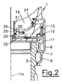
前記内燃エンジンは、複数の単一シリンダ1を有し、各単一シリンダ1は、シリンダハウジング2とシリンダライナ3とを有する。前記シリンダハウジング2は、その頂部において、単一シリンダヘッド4によって閉じられている。
The internal combustion engine has a plurality of single cylinders 1, and each single cylinder 1 has a
前記シリンダライナ3は、第1冷却ジャケット5と第2冷却ジャケット6とによって包囲され、前記第1冷却ジャケット5と第2冷却ジャケット6とは異なる冷却回路31,32に属し、前記シリンダハウジング2内で互いに分離され、これにより、前記単一シリンダヘッド4に対して別々に冷媒が供給される。前記第1冷却ジャケット5は前記第1冷却回路31の第1供給通路5aから延出し、前記第2冷却ジャケット6は前記第2冷却回路32の第2供給通路6aから延出している。前記第1冷却ジャケット5は、前記シリンダライナ3を包囲し、環状第1長手移行部(transfer)7を介して、前記シリンダライナ3の環状第1冷却通路8と、接線方向形成凹部(tangential milled recesses)9、径方向止まり孔又は径方向貫通穴に流れ接続されてトップランドリング領域10を冷却する。移行通路(transfer channel)11が、前記環状第1冷却通路8から延出し、この通路は第1移行開口部12と、前記シリンダ軸心1aに対して実質的に平行に配置された上昇通路(riser channel)13とを介して前記第1冷却チャンバ14内に開口している。前記環状第1通路領域8は、前記シリンダハウジング2内へと形成されている前記第2冷却ジャケット6によって取り囲まれている。前記第2冷却ジャケット6は、第2移行通路15と、前記シリンダハウジング2と前記単一シリンダヘッド4との間の、たとえば環状の、少なくとも1つの第2移行開口部16と、更に径方向の第1接続セン孔17を介して環状第2冷却通路18に流れ接続されてバルブシートリング43を冷却する。前記第2冷却通路18は、径方向接続通路19を介して少なくとも1つの軸心方向接続通路20に接続され、これは噴射ノズル等の中央コンポーネントを収納するためのスリーブ21に隣接するシリンダ軸心1aの方向に配設されている。更に、前記第2冷却ジャケット6は、径方向第2接続セン孔22を介して少なくとも1つの軸心方向接続通路20に接続されている。前記第2冷却通路18と前記第1および第2接続セン孔17および22は、実質的に、前記単一シリンダヘッド4のファイアデッキ23の法平面(ε)に配置され、前記軸心方向接続通路20と共に、前記第2冷却回路32によって供給される前記第2冷却チャンバ24を形成している。
The
前記軸心方向接続通路20は、底部部分冷却チャンバ25に接続され、これは、中間デッキ26によって、その上方に位置する前記第1冷却チャンバ14から分離されている。前記部分冷却チャンバ25は、第2流れ移行部(second flow transfer)27を介して前記第1冷却チャンバ14と接続されている。
The
前記軸心方向および径方向接続通路19,20は、好ましくは、セン孔によって形成される。
The axial and
前記中間デッキ26と前記スリーブ21との間には環状空隙28が形成され、その内部に、金属又はプラスチック製の環状バッフル29が挿入されている。当該バッフル29は、たとえば、溶接や接着等によって、前記スリーブ21に固定接続することができる。
An
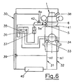
図6は、前記内燃エンジンの冷却システム30を略示している。当該冷却システム30は、第1冷却回路31と第2冷却回路32とを有し、第1冷却回路31は高温回路HTとして構成され、第2冷却回路32は低温回路NTとして構成されている。前記第1冷却回路31には第1冷媒ポンプ33が設けられ、前記第2冷却回路32には第2冷媒ポンプ34が設けられている。前記第1冷却回路31の冷媒は、前記第1冷媒ポンプ33から、高温インタークーラとして構成された第1インタークーラ35に流れ、当該インタークーラから前記シリンダハウジング2の前記第1ジャケット5に到達する。前記第2冷却回路32の冷媒は、前記第2冷媒ポンプ34によって、低温インタークーラとして構成された第2インタークーラ36へと運ばれ、ここから、それはオイルクーラ37を介して前記第2冷却ジャケット6に供給される。冷媒は、上述したように、前記シリンダハウジング2と単一シリンダヘッド4との前記冷却チャンバを通って流れ、ここで、前記二つの冷却回路31,32からの流れが前記単一シリンダヘッド4において合流し、共通の冷媒収集ライン38を介して再び前記単一シリンダ4を離れる。前記冷媒は、サーモスタットバルブ39を介して中央ユニットクーラ40に到達する。冷媒は、前記ユニットクーラ40の下流側で、前記第1冷却回路31と前記第2冷却回路32の二つの部分流へと分けられる。
FIG. 6 schematically shows the internal combustion
前記冷却回路31は、約85℃(前記第1冷却ジャケット5への入口温度)で作動し、ここで、前記トップランドリング領域10と、前記ピストンリング領域の第1溝9の領域とを十分に冷却するべく、冷媒は上方領域において前記シリンダライナ3の周りを流れる。その後、前記第1冷却回路31の冷媒は前記第1移行開口部12の領域を前記単一シリンダヘッド4へと流れる。
The
前記第2冷却回路32は、その温度に関して、前記第2冷却ジャケット6への入口温度が50℃から70℃の範囲となるように制御される。前記第2冷却回路32の冷媒は、実質的に、前記シリンダ軸心1a上の法平面(ε)において、前記単一シリンダヘッド4の前記ファイアデッキ23を通って流れる。前記第2冷却通路18と分配セン孔17および22は、前記単一シリンダヘッド4の燃焼チャンバルーフの近傍で前記シリンダ軸心1a上の法平面(ε)の領域に配置されて、吸気バルブと排気バルブとのバルブシートリング43を冷却する。前記流れは、前記単一シリンダヘッド4の中心に向かう方向に径方向に向けられ、前記バッフル29によって、前記スリーブ21の領域において偏向され、前記分配セン孔17および22に対する反対の方向で前記底部分冷却チャンバ25を通って流れる。前記第1および第2冷却回路31,32の流れは、前記上方の第1冷却チャンバ14の領域において目的的に合流され、その後、前記集合ライン38を通って前記単一シリンダヘッドヘッド4から共に出る。前記第2冷却回路32は、前記第2冷媒ジャケット6に入る前に、前記低温冷却回路NTから分岐させることが可能である。前記二つの冷却回路31,32の混合は、これら第1および第2冷却回路31,32間に混合バルブ41を設けることによって可能とされる。例えば、低温の内燃エンジンあるいはアイドリング運転において、前記高温回路HTからの熱水を前記低温回路NTに混合させることができる。前記混合バルブ41と制御バルブ42とは温度依存式に制御することが可能である。
The temperature of the
Claims (28)
Applications Claiming Priority (3)
| Application Number | Priority Date | Filing Date | Title |
|---|---|---|---|
| ATA50248/2012 | 2012-06-26 | ||
| ATA50248/2012A AT513053B1 (en) | 2012-06-26 | 2012-06-26 | Internal combustion engine, in particular large diesel engine |
| PCT/EP2013/062804 WO2014001181A1 (en) | 2012-06-26 | 2013-06-19 | Internal combustion engine, in particular large diesel engine |
Related Child Applications (1)
| Application Number | Title | Priority Date | Filing Date |
|---|---|---|---|
| JP2018122331A Division JP2018145971A (en) | 2012-06-26 | 2018-06-27 | Internal combustion engine, in particular large diesel engine |
Publications (1)
| Publication Number | Publication Date |
|---|---|
| JP2015521716A true JP2015521716A (en) | 2015-07-30 |
Family
ID=48670556
Family Applications (2)
| Application Number | Title | Priority Date | Filing Date |
|---|---|---|---|
| JP2015518984A Pending JP2015521716A (en) | 2012-06-26 | 2013-06-19 | Internal combustion engines, especially large diesel engines |
| JP2018122331A Pending JP2018145971A (en) | 2012-06-26 | 2018-06-27 | Internal combustion engine, in particular large diesel engine |
Family Applications After (1)
| Application Number | Title | Priority Date | Filing Date |
|---|---|---|---|
| JP2018122331A Pending JP2018145971A (en) | 2012-06-26 | 2018-06-27 | Internal combustion engine, in particular large diesel engine |
Country Status (5)
| Country | Link |
|---|---|
| US (1) | US9874133B2 (en) |
| JP (2) | JP2015521716A (en) |
| AT (1) | AT513053B1 (en) |
| DE (1) | DE112013003196A5 (en) |
| WO (1) | WO2014001181A1 (en) |
Cited By (4)
| Publication number | Priority date | Publication date | Assignee | Title |
|---|---|---|---|---|
| JP2016217191A (en) * | 2015-05-15 | 2016-12-22 | トヨタ自動車株式会社 | Cylinder head |
| JP2019070370A (en) * | 2017-10-11 | 2019-05-09 | 株式会社豊田自動織機 | Cooling device for cylinder head |
| JP2019163739A (en) * | 2018-03-20 | 2019-09-26 | ダイハツディーゼル株式会社 | Cylinder head cooling structure and cylinder head having cooling structure |
| JP2020521914A (en) * | 2017-06-02 | 2020-07-27 | アーファオエル・リスト・ゲーエムベーハー | Cylinder head with valve seat ring cooling |
Families Citing this family (15)
| Publication number | Priority date | Publication date | Assignee | Title |
|---|---|---|---|---|
| CN103993958A (en) * | 2014-05-30 | 2014-08-20 | 南车玉柴四川发动机股份有限公司 | Energy-saving and environment-friendly type high-power locomotive diesel engine |
| JP2017155591A (en) * | 2014-06-17 | 2017-09-07 | 川崎重工業株式会社 | Engine cooling system |
| DK179175B1 (en) * | 2016-03-16 | 2018-01-08 | Man Diesel & Turbo Filial Af Man Diesel & Turbo Se Tyskland | A cylinder cover for a large two-stroke turbocharged compression-ignited internal combustion engine |
| GB2548835B (en) * | 2016-03-29 | 2018-04-18 | Ford Global Tech Llc | A cooling system |
| WO2018057305A1 (en) * | 2016-09-20 | 2018-03-29 | Cummins Inc. | Systems and methods for avoiding structural failure resulting from hot high cycles using a cylinder head cooling arrangement |
| WO2018156682A1 (en) * | 2017-02-24 | 2018-08-30 | Cummins Inc. | Engine cooling system including cooled exhaust seats |
| CH713618A1 (en) * | 2017-03-22 | 2018-09-28 | Liebherr Machines Bulle Sa | Liquid-cooled internal combustion engine. |
| AT520289B1 (en) * | 2017-08-09 | 2019-03-15 | Avl List Gmbh | CYLINDER HEAD FOR AN INTERNAL COMBUSTION ENGINE |
| CN108223096B (en) * | 2018-02-07 | 2021-03-12 | 广西玉柴机器股份有限公司 | Cooling system of V-shaped multi-cylinder diesel engine |
| JP6716723B2 (en) * | 2018-10-29 | 2020-07-01 | 株式会社小松製作所 | Cylinder head and engine |
| AT522271B1 (en) * | 2019-03-20 | 2021-02-15 | Avl List Gmbh | COMBUSTION ENGINE WITH AT LEAST ONE CYLINDER |
| US10876462B1 (en) * | 2019-07-18 | 2020-12-29 | Ford Global Technologies, Llc | Coolant jacket insert |
| DE102019123878B3 (en) * | 2019-09-05 | 2021-03-11 | Mtu Friedrichshafen Gmbh | Crankcase for an internal combustion engine, internal combustion engine |
| AT524536B1 (en) * | 2021-03-15 | 2022-07-15 | Avl List Gmbh | LIQUID-COOLED INTERNAL ENGINE |
| US11525419B1 (en) * | 2021-10-26 | 2022-12-13 | Progress Rail Locomotive Inc. | Engine power module and cylinder head for same |
Citations (3)
| Publication number | Priority date | Publication date | Assignee | Title |
|---|---|---|---|---|
| JPS54155328A (en) * | 1978-05-26 | 1979-12-07 | Sulzer Ag | Device for cooling cylinder cover of fourrprocess diesel engine |
| JPS5837920U (en) * | 1981-09-04 | 1983-03-11 | 三菱自動車工業株式会社 | engine cooling system |
| WO1996009467A1 (en) * | 1994-09-19 | 1996-03-28 | Motoren-Werke Mannheim Aktiengesellschaft | Cylinder head |
Family Cites Families (15)
| Publication number | Priority date | Publication date | Assignee | Title |
|---|---|---|---|---|
| AT283824B (en) * | 1966-02-23 | 1970-08-25 | H C Hans Dipl Ing Dr Dr List | Internal combustion engine with exhaust gas turbocharger and charge air cooler |
| DE2514592C2 (en) * | 1975-04-03 | 1982-10-14 | Mtu Motoren- Und Turbinen-Union Friedrichshafen Gmbh, 7990 Friedrichshafen | Single cylinder head |
| JPS5557614A (en) * | 1978-10-23 | 1980-04-28 | Nissan Motor Co Ltd | Colling device for internal combustion engine |
| JPS5837920A (en) | 1981-08-28 | 1983-03-05 | Mitsubishi Electric Corp | Liquid phase epitaxy growing apparatus |
| JPS5865927A (en) * | 1981-10-14 | 1983-04-19 | Toyota Motor Corp | Cooling device of cylinder block in internal-combustion engine |
| JPH0660745B2 (en) | 1986-05-08 | 1994-08-10 | 松下電器産業株式会社 | Hot water supply bath heating system |
| US4815419A (en) * | 1986-10-23 | 1989-03-28 | Mitsubishi Jidosha Kogyo Kabushiki Kaisha | Engine cooling apparatus |
| JPH0660745A (en) | 1992-08-10 | 1994-03-04 | Furukawa Electric Co Ltd:The | Manufacture of flat cable |
| JPH0660745U (en) * | 1993-01-29 | 1994-08-23 | 富士重工業株式会社 | Engine cooling system |
| AT92U1 (en) * | 1993-03-23 | 1995-01-25 | Avl Verbrennungskraft Messtech | INTERNAL COMBUSTION ENGINE WITH AT LEAST ONE GAS EXCHANGE CHANNEL PER CYLINDER |
| IT1308421B1 (en) | 1999-03-11 | 2001-12-17 | Fiat Ricerche | COOLING SYSTEM FOR AN INTERNAL COMBUSTION ENGINE. |
| JP3800875B2 (en) * | 1999-08-05 | 2006-07-26 | トヨタ自動車株式会社 | In-cylinder injection spark ignition internal combustion engine |
| DE102004024289A1 (en) | 2004-05-15 | 2005-12-15 | Deere & Company, Moline | Cooling system for a vehicle |
| DE102004047452A1 (en) * | 2004-09-30 | 2006-04-13 | Fev Motorentechnik Gmbh | Cooling system for internal combustion engine has controllable setting member to regulate distribution of cooling air stream between two cooling circuits in dependence on measured parameter |
| DE102011101337A1 (en) * | 2011-05-12 | 2011-12-01 | Daimler Ag | Circuit arrangement for refrigeration of auxiliary unit of internal combustion engine of hybrid vehicle e.g. motor car, has low-temperature circuit linked with high-temperature circuit, so that coolant is passed via high-temperature circuit |
-
2012
- 2012-06-26 AT ATA50248/2012A patent/AT513053B1/en active
-
2013
- 2013-06-19 JP JP2015518984A patent/JP2015521716A/en active Pending
- 2013-06-19 WO PCT/EP2013/062804 patent/WO2014001181A1/en active Application Filing
- 2013-06-19 DE DE112013003196.5T patent/DE112013003196A5/en active Pending
- 2013-06-19 US US14/410,721 patent/US9874133B2/en active Active
-
2018
- 2018-06-27 JP JP2018122331A patent/JP2018145971A/en active Pending
Patent Citations (3)
| Publication number | Priority date | Publication date | Assignee | Title |
|---|---|---|---|---|
| JPS54155328A (en) * | 1978-05-26 | 1979-12-07 | Sulzer Ag | Device for cooling cylinder cover of fourrprocess diesel engine |
| JPS5837920U (en) * | 1981-09-04 | 1983-03-11 | 三菱自動車工業株式会社 | engine cooling system |
| WO1996009467A1 (en) * | 1994-09-19 | 1996-03-28 | Motoren-Werke Mannheim Aktiengesellschaft | Cylinder head |
Cited By (4)
| Publication number | Priority date | Publication date | Assignee | Title |
|---|---|---|---|---|
| JP2016217191A (en) * | 2015-05-15 | 2016-12-22 | トヨタ自動車株式会社 | Cylinder head |
| JP2020521914A (en) * | 2017-06-02 | 2020-07-27 | アーファオエル・リスト・ゲーエムベーハー | Cylinder head with valve seat ring cooling |
| JP2019070370A (en) * | 2017-10-11 | 2019-05-09 | 株式会社豊田自動織機 | Cooling device for cylinder head |
| JP2019163739A (en) * | 2018-03-20 | 2019-09-26 | ダイハツディーゼル株式会社 | Cylinder head cooling structure and cylinder head having cooling structure |
Also Published As
| Publication number | Publication date |
|---|---|
| DE112013003196A5 (en) | 2015-03-19 |
| US20150211408A1 (en) | 2015-07-30 |
| US9874133B2 (en) | 2018-01-23 |
| JP2018145971A (en) | 2018-09-20 |
| AT513053B1 (en) | 2014-03-15 |
| AT513053A1 (en) | 2014-01-15 |
| WO2014001181A1 (en) | 2014-01-03 |
Similar Documents
| Publication | Publication Date | Title |
|---|---|---|
| JP2018145971A (en) | Internal combustion engine, in particular large diesel engine | |
| US10787952B2 (en) | Exhaust side block insert, cylinder block assembly including the same, and heat management system of engine including the same | |
| JP2018145971A5 (en) | ||
| US8061309B2 (en) | Cooling system | |
| RU2589556C2 (en) | Engine system and method of reducing production cost thereof | |
| US9212620B2 (en) | Coolant jackets for an internal combustion engine and method of control | |
| CN107152349B (en) | Cylinder head of internal combustion engine | |
| US9541093B2 (en) | Multi-stage turbocharger arrangement | |
| CN1877107B (en) | Internal combustion engine | |
| CN109812350B (en) | Cylinder head with integrated exhaust manifold and engine cooling system comprising same | |
| CN106988854B (en) | Cooling system for internal combustion engine | |
| CN105937461A (en) | A water jacket for an internal combustion engine | |
| CN108894888B (en) | Engine cylinder cover | |
| CN108035818B (en) | Cylinder head for a prechamber spark plug | |
| CN107313872A (en) | The cylinder head of explosive motor | |
| US7845339B2 (en) | Exhaust gas recirculation cooler coolant plumbing configuration | |
| CN103080520A (en) | Coolant jacket for a liquid-cooled cylinder head | |
| CN107532500B (en) | Coolant circuit for liquid-cooled transmission | |
| JP4985210B2 (en) | Cylinder head and heater piping structure | |
| CN114233507B (en) | Cooling water jacket of engine cylinder cover | |
| CN115126620A (en) | Liquid cooling type internal combustion engine | |
| CN104685180A (en) | Liquid cooling system for an internal combustion engine of a vehicle | |
| JP2006161689A (en) | Cooling water passage structure for engine with supercharger | |
| CN114174659A (en) | Cooling optimized cylinder head and optimized cylinder head cooling method | |
| CN220353953U (en) | Cylinder head cooling water jacket, cylinder head, engine and vehicle |
Legal Events
| Date | Code | Title | Description |
|---|---|---|---|
| A621 | Written request for application examination |
Free format text: JAPANESE INTERMEDIATE CODE: A621 Effective date: 20160610 |
|
| A977 | Report on retrieval |
Free format text: JAPANESE INTERMEDIATE CODE: A971007 Effective date: 20170313 |
|
| A131 | Notification of reasons for refusal |
Free format text: JAPANESE INTERMEDIATE CODE: A131 Effective date: 20170328 |
|
| A601 | Written request for extension of time |
Free format text: JAPANESE INTERMEDIATE CODE: A601 Effective date: 20170628 |
|
| A601 | Written request for extension of time |
Free format text: JAPANESE INTERMEDIATE CODE: A601 Effective date: 20170828 |
|
| A521 | Request for written amendment filed |
Free format text: JAPANESE INTERMEDIATE CODE: A523 Effective date: 20170926 |
|
| A02 | Decision of refusal |
Free format text: JAPANESE INTERMEDIATE CODE: A02 Effective date: 20180227 |