JP2015519747A - Magnetic shield three-phase rotary transformer - Google Patents
Magnetic shield three-phase rotary transformer Download PDFInfo
- Publication number
- JP2015519747A JP2015519747A JP2015510856A JP2015510856A JP2015519747A JP 2015519747 A JP2015519747 A JP 2015519747A JP 2015510856 A JP2015510856 A JP 2015510856A JP 2015510856 A JP2015510856 A JP 2015510856A JP 2015519747 A JP2015519747 A JP 2015519747A
- Authority
- JP
- Japan
- Prior art keywords
- coil
- transformer
- slot
- axis
- phase
- Prior art date
- Legal status (The legal status is an assumption and is not a legal conclusion. Google has not performed a legal analysis and makes no representation as to the accuracy of the status listed.)
- Withdrawn
Links
Images


Classifications
-
- H—ELECTRICITY
- H01—ELECTRIC ELEMENTS
- H01F—MAGNETS; INDUCTANCES; TRANSFORMERS; SELECTION OF MATERIALS FOR THEIR MAGNETIC PROPERTIES
- H01F38/00—Adaptations of transformers or inductances for specific applications or functions
- H01F38/18—Rotary transformers
-
- H—ELECTRICITY
- H01—ELECTRIC ELEMENTS
- H01F—MAGNETS; INDUCTANCES; TRANSFORMERS; SELECTION OF MATERIALS FOR THEIR MAGNETIC PROPERTIES
- H01F27/00—Details of transformers or inductances, in general
- H01F27/28—Coils; Windings; Conductive connections
- H01F27/2823—Wires
-
- H—ELECTRICITY
- H01—ELECTRIC ELEMENTS
- H01F—MAGNETS; INDUCTANCES; TRANSFORMERS; SELECTION OF MATERIALS FOR THEIR MAGNETIC PROPERTIES
- H01F30/00—Fixed transformers not covered by group H01F19/00
- H01F30/06—Fixed transformers not covered by group H01F19/00 characterised by the structure
- H01F30/12—Two-phase, three-phase or polyphase transformers
Abstract
1次部分(11;12)および2次部分(12;11)を備える三相変圧器(10)であって、1次部分(11)が、強磁性材料で作られた第1の本体、および1次コイル(24、25、26、27)を備え、2次部分(12)が、強磁性材料で作られた第2の本体、および2次コイル(28、29、30、31)を備え、第1の本体が、軸線Aの第1の環状スロット(22)および軸線Aの第2の環状スロット(23)を画定し、1次コイルが、第1のスロット(22)に軸線Aの第1のトロイダルコイル(24)、第1のスロット(22)に軸線Aの第2のトロイダルコイル(25)、第2のスロット(23)に軸線Aの第3のトロイダルコイル(26)、および第2のスロット(23)に軸線Aの第4のトロイダルコイル(27)を備え、第2のコイル(25)および第3のコイル(26;226)が直列に接続されている、三相変圧器。A three-phase transformer (10) comprising a primary part (11; 12) and a secondary part (12; 11), wherein the primary part (11) is made of a ferromagnetic material; And a primary coil (24, 25, 26, 27), a secondary part (12) comprising a second body made of a ferromagnetic material, and a secondary coil (28, 29, 30, 31). The first body defines a first annular slot (22) of axis A and a second annular slot (23) of axis A, and the primary coil is in axis A in the first slot (22). A first toroidal coil (24), a second toroidal coil (25) of axis A in the first slot (22), a third toroidal coil (26) of axis A in the second slot (23), And a second slot (23) with a fourth toroidal coil (27) of axis A A second coil (25) and the third coil (26; 226) are connected in series, a three-phase transformer.
Description
本発明は、変圧器の一般的分野に関する。特に、本発明は、回転三相変圧器に関する。 The present invention relates to the general field of transformers. In particular, the present invention relates to a rotating three-phase transformer.
回転三相変圧器は、互いに対して回転する2つの軸の間の接触なしでエネルギーおよび/または信号を伝達する働きをする。 A rotating three-phase transformer serves to transfer energy and / or signals without contact between two axes that rotate relative to each other.
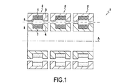
図1および図2は、先行技術のそれぞれの回転三相変圧器1を示している。
1 and 2 show respective prior art rotary three-
変圧器1は、相U、V、およびWに対応する3つの回転単相変圧器2を有する。各回転単相変圧器2は、軸線Aを中心として互いに対して回転する部分3および部分4を有する。例示として、部分3は固定子であり、部分4は回転子であり、または逆もまた同じである。変形においては、部分3および部分4は、両方とも、静止座標系(図示せず)に対して回転可能である。トロイダルコイル5は、部分3の強磁性材料で作られた本体によって画定されたスロット6に収容されている。トロイダルコイル7は、部分4の強磁性材料で作られた本体によって画定されたスロット8に収容されている。回転単相変圧器2ごとに、コイル5および7は、1次コイルおよび2次コイルを形成する(または、逆もまた同じである)。
The
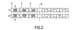
図1は、部分3が軸線Aを中心として部分4を取り囲む「U字状」と呼ばれる変形を示しているが、図2は、部分3および部分4が軸線方向に並んでいる、「E字状」または「ポット型」と呼ばれる変形を示している。 FIG. 1 shows a variant called “U-shape” in which the part 3 surrounds the part 4 around the axis A, but FIG. 2 shows that the part 3 and the part 4 are aligned in the axial direction. A variant called “shape” or “pot type” is shown.
図1または図2の三相変圧器1は、磁束を結合することが可能である強制磁束を有する静止三相変圧器とは異なって、相の各々の磁束を最大限利用することが可能でないので、大きな重量および体積を有する。そのうえ、図2の例においては、平衡化された抵抗を保存するために、回転軸線と相との間の距離に応じて異なる断面の導電体を使用することが必要である。
The three-
文献米国特許出願公開第2011/0050377号明細書は、4列回転三相変圧器を記載している。その変圧器は、かなりの重量および体積を有する。また、その文献は、5列回転三相変圧器を記載している。その変圧器は、かなりの重量および体積を有する。そのうえ、これは、スロットを介して磁気回路の中央列の中を通過する半径方向巻線を利用し、ここでこのような巻線は、図1および図2の変圧器に使用されるトロイダル巻線よりも実施するのがより複雑である。 The document US 2011/0050377 describes a four-row rotating three-phase transformer. The transformer has a considerable weight and volume. The document also describes a five-row rotating three-phase transformer. The transformer has a considerable weight and volume. Moreover, it utilizes radial windings that pass through slots in the central row of the magnetic circuit, where such windings are toroidal windings used in the transformers of FIGS. It is more complicated to implement than a line.
したがって、三相変圧器のトポロジーを改善する必要がある。 Therefore, it is necessary to improve the topology of the three-phase transformer.
本発明は、1次部分および2次部分を有する三相変圧器にして、
・1次部分が、強磁性材料で作られた第1の本体および1次コイルを備え、2次部分が、強磁性材料で作られた第2の本体および2次コイルを備え、
・第1の本体が、軸線Aの第1の環状スロットおよび軸線Aの第2の環状スロットを画定し、第1のスロットが、第1の側脚、中央脚、およびリングによって画定され、第2のスロットが、中央脚、第2の側脚、およびリングによって画定され、
・1次コイルが、相Uに対応する第1のスロットに軸線Aの第1のトロイダルコイル、第1のスロットに軸線Aの第2のトロイダルコイル、第2のスロットに軸線Aの第3のトロイダルコイル、および相Wに対応する第2のスロットに軸線Aの第4のトロイダルコイルを備え、相Vに対応する第2のコイルおよび第3のコイルが、直列に接続されている、三相変圧器であって、
第2のコイルおよび第3のコイルの巻回および接続方向が、第2のコイルおよび第3のコイルに流れる電流について、第2のコイルの第1の磁位に対応し、第3のコイルの第1の磁位と逆の第2の磁位に対応する、三相変圧器を提供する。
The present invention provides a three-phase transformer having a primary part and a secondary part,
The primary part comprises a first body and a primary coil made of a ferromagnetic material, the secondary part comprises a second body and a secondary coil made of a ferromagnetic material;
The first body defines a first annular slot of axis A and a second annular slot of axis A, the first slot being defined by a first side leg, a central leg and a ring; Two slots are defined by a central leg, a second side leg, and a ring;
The primary coil has a first toroidal coil of axis A in the first slot corresponding to phase U, a second toroidal coil of axis A in the first slot, and a third toroid of axis A in the second slot; A three-phase coil comprising a toroidal coil and a fourth toroidal coil of axis A in a second slot corresponding to phase W, wherein the second and third coils corresponding to phase V are connected in series A transformer,
The winding and connecting direction of the second coil and the third coil correspond to the first magnetic position of the second coil with respect to the current flowing through the second coil and the third coil, A three-phase transformer is provided that corresponds to a second magnetic potential opposite to the first magnetic potential.
この変圧器においては、三相電流が適切な方向に1次コイルに流れるようにされる場合に、1次コイルの巻回方向を考えると、第1および第2の1次コイルの磁位は反対であり、第3および第4の1次コイルの磁位は反対である。それは、変圧器が体積および重量に関して低減された寸法となり得るようにする磁束結合につながる。特に、それは、強制された鎖交磁束を有する3列三相静止変圧器の結合された磁束を脚に再現することにつながる。そのうえ、変圧器の1次コイルは、軸線Aの簡単なトロイダルコイルのみを利用し、したがって、構造が特に簡単であり得るようにする。 In this transformer, when the winding direction of the primary coil is considered when the three-phase current is caused to flow through the primary coil in an appropriate direction, the magnetic potentials of the first and second primary coils are The opposite is true, and the magnetic potentials of the third and fourth primary coils are opposite. It leads to flux coupling that allows the transformer to be reduced in size and volume. In particular, it leads to reproducing the combined magnetic flux of the three-row three-phase static transformer with forced interlinkage flux in the leg. Moreover, the primary coil of the transformer utilizes only a simple toroidal coil of axis A, so that the structure can be particularly simple.
一実施形態においては、1次部分および2次部分は、軸線Aを中心として互いに対して回転可能である。 In one embodiment, the primary portion and the secondary portion are rotatable relative to each other about axis A.
こうした状況では、本発明は、その結合した磁束により、特に3つの単相回転変圧器を使用することに対して低減された重量および体積を有する回転三相変圧器を提供する。 In such a situation, the present invention provides a rotating three-phase transformer having a reduced weight and volume due to its combined magnetic flux, especially for using three single-phase rotating transformers.
一実施形態においては、第2の本体は、軸線Aの第1の環状2次スロットおよび軸線Aの第2の環状2次スロットを画定し、第1の2次スロットは、第1の2次側脚、2次中央脚、および2次リングによって画定され、第2の2次スロットは、2次中央脚、第2の2次側脚、および2次リングによって画定され、2次コイルは、相Uに対応する第1の2次スロットに軸線Aの第1のトロイダル2次コイル、第1の2次スロットに軸線Aの第2のトロイダル2次コイル、第2の2次スロットに軸線Aの第3のトロイダル2次コイル、および相Wに対応する第2の2次ノッチに軸線Aの第4のトロイダル2次コイルを備え、相Vに対応する第2の2次コイルおよび第3の2次コイルは、直列に接続されている。 In one embodiment, the second body defines a first annular secondary slot of axis A and a second annular secondary slot of axis A, wherein the first secondary slot is the first secondary slot. The secondary leg is defined by the side leg, the secondary central leg, and the secondary ring, the second secondary slot is defined by the secondary central leg, the second secondary side leg, and the secondary ring, A first toroidal secondary coil of axis A in the first secondary slot corresponding to phase U, a second toroidal secondary coil of axis A in the first secondary slot, and axis A in the second secondary slot. A third toroidal secondary coil, and a second toroidal secondary coil of axis A at the second secondary notch corresponding to phase W, the second secondary coil corresponding to phase V and the third The secondary coils are connected in series.
この実施形態においては、2次コイルは、1次コイルと同じ原理で作られている。したがって、2次コイルはまた、変圧器の重量および体積を制限することに寄与し、軸線Aのトロイダルコイルのみを使用しながら変圧器が構築され得るようにする。 In this embodiment, the secondary coil is made on the same principle as the primary coil. Thus, the secondary coil also contributes to limiting the weight and volume of the transformer, allowing the transformer to be constructed using only the axis A toroidal coil.
一実施形態においては、第2の本体は、軸線Aの第1の環状2次スロットおよび軸線Aの第2の環状2次スロットを画定し、第1の2次スロットは、第1の2次側脚、2次中央脚、および2次リングによって画定され、第2の2次スロットは、2次中央脚、第2の2次側脚、および2次リングによって画定され、
・2次コイルは、直列に接続された1つまたは複数の2次コイルを備え、前記2次コイルは、前記2次脚に巻回されて、前記2次脚におけるスロットの中を通過する。
In one embodiment, the second body defines a first annular secondary slot of axis A and a second annular secondary slot of axis A, wherein the first secondary slot is the first secondary slot. A second secondary slot is defined by the secondary central leg, the second secondary side leg, and the secondary ring, defined by the side leg, the secondary central leg, and the secondary ring;
The secondary coil comprises one or more secondary coils connected in series, the secondary coil being wound around the secondary leg and passing through a slot in the secondary leg.
この実施形態においては、2次コイルは、1次コイルの原理と異なる原理で作られているが、やはり同様な利点を有する。したがって、2次コイルはまた、変圧器の重量および体積を制限することに寄与し、大部分において軸線Aのトロイダルコイルを使用しながら変圧器が構築され得るようにする。 In this embodiment, the secondary coil is made on a principle different from that of the primary coil, but still has similar advantages. Thus, the secondary coil also contributes to limiting the weight and volume of the transformer, allowing the transformer to be constructed using the toroidal coil of axis A for the most part.
一実施形態においては、第1の側脚および第1の2次側脚は、互いに一致し、エアギャップによって分離され、第1の中央脚および第1の2次中央脚は、互いに一致し、エアギャップによって分離され、第2の側脚および第2の2次測脚は、互いに一致し、エアギャップによって分離される。 In one embodiment, the first side leg and the first secondary side leg coincide with each other and are separated by an air gap, the first central leg and the first secondary central leg coincide with each other; The second side leg and the second secondary leg are separated from each other by the air gap and are separated from each other by the air gap.
1次部分は、軸線Aに対して2次部分を取り囲んでもよく、または逆もまた同じであってもよい。それは、「U字状」であると呼ばれる変圧器を作ることに対応する。 The primary part may surround the secondary part relative to the axis A, or vice versa. It corresponds to making a transformer called “U-shaped”.
1次部分および2次部分は、軸線Aの方向に並んで置かれていてもよい。それは、「E字状」または「ポット型」であると呼ばれる変圧器を作ることに対応する。 The primary part and the secondary part may be placed side by side in the direction of the axis A. It corresponds to making a transformer called “E-shaped” or “pot-shaped”.
一実施形態においては、1次部分および2次部分は、互いに対して静止している。本発明による静止変圧器は、本発明による回転変圧器と同じ利点を有する。 In one embodiment, the primary part and the secondary part are stationary relative to each other. A static transformer according to the invention has the same advantages as a rotary transformer according to the invention.
一実施形態においては、強磁性材料で作られた第1および第2の本体は、1次コイルおよび2次コイルを完全に取り囲む。 In one embodiment, the first and second bodies made of a ferromagnetic material completely surround the primary and secondary coils.
こうした状況では、変圧器は磁気的にシールドされる。 In these situations, the transformer is magnetically shielded.
本発明の他の特徴および利点は、添付の図面を参照して行われる次の説明から明らかになり、図面は限定的な性質を有さない実施形態を示す。 Other features and advantages of the present invention will become apparent from the following description, given with reference to the accompanying drawings, which show embodiments that are not of a limiting nature.
図3は、本発明の第1の実施形態における回転変圧器10の断面図である。変圧器10は、強制された鎖交磁束を有する磁気シールド三相回転変圧器である。
FIG. 3 is a cross-sectional view of the
変圧器10は、軸線Aを中心として互いに対して回転するのに適した部分11および部分12を備える。例示として、部分11は固定子であり、部分12は回転子であり、または逆もまた同じである。変形においては、部分11および部分12は、両方とも、静止座標系(図示せず)に対して回転可能である。
The
部分12は、軸線Aのリング13と、強磁性材料で作られた3つの脚14、15、および16とを備える。脚14、15、および16の各々は、リング13から始まって軸線Aから半径方向に離れるように延在する。脚14は、リング13の一方の端部にあり、脚16は、リング13の他方の端部にあり、脚15は、脚14と脚16との間にある。リング13ならびに脚14および15は、半径方向外方向に開いた環状スロット34を画定する。リング13ならびに脚15および16は、半径方向外方向に開いた環状スロット35を画定する。全般的に、リング13ならびに脚14、15、および16は、半径方向外方向に開いた2つの環状スロット34および35を画定する強磁性材料の本体を形成する。
The
部分11は、軸線Aのリング17と、強磁性材料で作られた3つの脚18、19、および20とを備える。リング17は、リング13を取り囲む。脚18、19、および20の各々は、リング17から始まって軸線Aに向かって半径方向に延在する。脚18は、リング17の一方の端部にあり、脚20は、リング17の他方の端部にあり、脚19は、脚18と脚20との間にある。リング17ならびに脚18および19は、半径方向内方向に開いた環状スロット22を画定する。リング17ならびに脚19および20は、半径方向内方向に開いた環状スロット23を画定する。全般的に、リング17ならびに脚18、19、および20は、半径方向内方向に開いた2つの環状スロット22および23を画定する強磁性材料の本体を形成する。
脚14および18、15および19、ならびにまた16および20は、エアギャップ21を画定するように1対で互いに面しており、それによって、変圧器10の列を形成する。
リング13および17は、脚14〜16、および18〜20と一緒に、変圧器10の磁気回路を形成する。したがって、変圧器10は、3列変圧器である。より正確には、変圧器10の磁気回路は、第1の列(脚14および18に対応する)、第2の列(脚15および19に対応する)、および第3の列(脚16および20に対応する)を有する。図4は、図10の変圧器の磁気回路を示す分解斜視図である。
図3をもう一度参照して、変圧器10は、部分11に固締されたコイル24、25、26、および27と、部分12に固締されたコイル28、29、30、および31とを備える。以下、表記pおよびsは、コイル24〜27が変圧器10の1次コイルであり、コイル28〜31が変圧器10の2次コイルである構成を基準にして使用される。しかしながら、1次および2次は、本質的に、説明されている例に対して逆にされることがある。
Referring once again to FIG. 3, the
コイル24は、変圧器10の相Upに対応する軸線Aのトロイダルコイルである。これは、スロット22に位置する。コイル25は、軸線Aのトロイダルコイルであり、これは、スロット22に位置する。コイル26は、軸線Aのトロイダルコイルであり、これは、スロット23に位置し、これは、コイル25と直列に接続されている。コイル25および26は、変圧器10の相Vpに対応する。最後に、コイル27は、変圧器10の相Wpに対応する軸線Aのトロイダルコイルである。これは、スロット23に位置する。コイル24〜27の各々は、n1の巻数を有する。用語「軸線Aのトロイダルコイル」は、その巻数を有するコイルが軸線Aに巻回されることを意味するのに使用される。用語「トロイダル」は、軸線を中心として円を回転させることによって生じるような立体を指す限定的な意味に使用されない。対照的に、図示された例の場合ように、トロイダルコイルの断面は、特に長方形であってもよい。
相応して、コイル28は、変圧器10の相Upに対応する軸線Aのトロイダルコイルである。これは、スロット34に位置する。コイル29は、軸線Aのトロイダルコイルであり、これは、スロット34に位置する。コイル30は、軸線Aのトロイダルコイルであり、これは、スロット35に位置し、これは、コイル29と直列に接続されている。コイル29および30は、変圧器10の相Vsに対応する。最後に、コイル31は、変圧器10の相Wsに対応する軸線Aのトロイダルコイルである。これは、スロット35に位置する。
Correspondingly, the
コイル24、25、28、および29は、リング13に置かれている磁心32を取り囲む。用語「磁心」は、コイルによって発生する同一方向の磁束が多数である磁気回路の部分を意味するのに使用される。したがって、コイル24および25に流れる電流は、磁心32における磁位に対応する。相応して、コイル26、27、30、および31は、リング13に置かれている磁心33を取り囲む。したがって、コイル26および27に流れる電流は、磁心33における磁位に対応する。
図5Aを参照して、いかに変圧器10が動作するかについて説明が続く。図5Aにおいては、次の表記が使用される。
With reference to FIG. 5A, the description continues as to how the
・Ap、Bp、およびCpは、変圧器10の1次コイルの入口点である。図3の相U、V、およびWは、それぞれ図4Aの相A、B、およびCに対応するが、同じ対応が2次コイルに使用されるという条件で、すべての他の対応型が可能である。
A p , B p , and C p are the entry points of the primary coil of the
・Iap、Ibp、およびIcpは、点Ap、Bp、およびCpにおけるそれぞれの入力電流である。 I ap , I bp , and I cp are the respective input currents at points A p , B p , and C p .
・Oap、Obp、およびOcpは、すべての種類の静止三相変圧器(スター−スター、スター−デルタ、デルタ−デルタ、デルタ−スター、Z字形、・・・)と同一の可能な電気的結合を作る接続点である。 O ap , O bp , and O cp are the same possible for all types of static three-phase transformers (star-star, star-delta, delta-delta, delta-star, Z-shaped, ...) A connection point that creates electrical coupling.
・黒ドットは、コイルに流れる電流と対応する磁位の方向との間の関係を示す。点がコイルの左側にある場合には、コイルは、発生する磁位が入力電流と同じ方向にあるような方向に巻回される(時計回り巻回)。点がコイルの右側にある場合には、巻回方向は、発生する磁位を入力電流に対して反対の方向にさせる(反時計回り方向の巻回)。 Black dots indicate the relationship between the current flowing through the coil and the corresponding magnetic potential direction. When the point is on the left side of the coil, the coil is wound in such a direction that the generated magnetic potential is in the same direction as the input current (clockwise winding). When the point is on the right side of the coil, the winding direction causes the generated magnetic potential to be opposite to the input current (counterclockwise winding).
・Pa、−Pb、Pb、およびPcは、それぞれ電流Iap、Ibp、およびIcpに対応する磁心32および33における磁位であり、
・As、Bs、Cs、Oas、Obs、およびOcsは、出口点および2次コイルに接続するための点である。
Pa, -Pb, Pb, and Pc are the magnetic potentials in the
A s , B s , C s , O as , O bs , and O cs are points for connecting to the exit point and the secondary coil.
図5Aに示されたコイル25および26の巻回方向および直列接続を考えると、電流Ibpは、磁心32において、磁位Paと反対の方向の磁位Pbに対応し、磁心33において、磁位Pcと反対の方向の磁位Pbに対応する。
Considering the winding direction and series connection of the
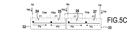
図5B〜図5Eは、図5Aの図と同様な図であり、ここで1次コイルのみが示されており、これらは、同じ効果が得られるようにする変形の直列接続および巻回方向を示している。 5B-5E are views similar to the view of FIG. 5A, where only the primary coil is shown, which has a modified series connection and winding direction to achieve the same effect. Show.
したがって、変圧器10は、絶対値が等しく、各々の磁心32および33において方向が反対であり、かつ2つの磁心の間の対称軸線Bに対して対称である磁位Pa、Pb、およびPcを生成することを可能にする。2π/3の位相オフセットを有する2つの磁位源は、2π/3で相互に位相オフセットされる3つの三相電圧源が再構築され得るので、したがって、変圧器10は、強制磁束を有する(鎖交磁束を有する)三相変圧器として動作することができる。
Thus, the
2次コイルの相における巻数の数がn2と書かれている場合には、任意の三相変圧器の場合のように、電圧の比が、第1の近似値にn2/n1で与えられ、電流の比は、n1/n2で与えられる。回転変圧器10は、複数の2次コイルをもつ可能性を含めて、(強制された)鎖交磁束を有する任意の静止三相変圧器と同じ特性を有する。図5A〜図5Eの巻線トポロジーを有する磁気回路によって行われる磁気結合は、単相変圧器に対して、強制磁束を有する静止三相変圧器の場合と同じ3/2の結合係数を、発生する磁束において有することを可能にする。最良の結合係数を有するために、磁気列の各々の磁気抵抗は、主としてエアギャップに起因して等しいことが必要である。詳細には、強制磁束を有する静止三相変圧器の場合のように、磁性材料の磁気抵抗よりも高い列の各々において等価の磁気抵抗を発生させることが必要である。回転変圧器においては、これは、本質的にエアギャップによって実現される。
If the number of turns in the phase of the secondary coil is written as n 2 , the voltage ratio is n 2 / n 1 to the first approximation as in the case of any three-phase transformer Given, the ratio of currents is given by n 1 / n 2 . The
変圧器10は、いくつかの利点を有する。
The
特に、磁気回路は完全にコイル24〜31を取り囲むということが理解できる。したがって、変圧器10は、磁気的にシールドされる。そのうえ、コイル24〜31は、すべて軸線Aのトロイダルコイルである。したがって、変圧器10は、形状がより複雑なコイルを必要としない。
In particular, it can be seen that the magnetic circuit completely surrounds the coils 24-31. Therefore, the
そのうえ、変圧器10の相は、インダクタンスおよび抵抗が平衡化されていてもよい。
Moreover, the phase of the
詳細には、磁気回路の幾何学的形状が各半コイルにおいて磁束の半分を相殺する働きをするので、合計2*n1の巻数を有する相Vのインダクタンスは、やはり相UおよびWのインダクタンスに等しく、各々は、n1の巻数を有する。より正確には、コイル25は、コイル24と同じ数の巻数を有し、同じ磁気回路と分かり、同様のことが、コイル26およびコイル27にあてはまる。しかし、コイル24および27は、同じ数の巻数で対称であり、したがって、それらのインダクタンスは等しい。コイル25は、コイル26と反対の方向に巻回され、したがって中央列(脚15および19によって形成される)の並列接続のため相殺されるその磁束の半分を有し、同様のことが、コイル26にあてはまる。したがって、コイル25および26の全インダクタンスは、コイル24および27の全インダクタンスに等しい。
Specifically, because the geometry of the magnetic circuit serves to cancel half of the magnetic flux in each half coil, the inductance of phase V having a total of 2 * n 1 turns will again be the inductance of phases U and W. Equally, each has n 1 turns. More precisely, the
抵抗は、コイルにおける導体の断面を変更することによって平衡化できる。n1の巻数を有する相UおよびWの断面は等しいが、2*n1の巻数を有する相Vの断面は、前述の断面の2倍である。詳細には、相において平衡化された抵抗を保存するために、2倍長い相は、また、長さのその増加を補償するために2倍の断面積を有さなければならない。 The resistance can be balanced by changing the cross section of the conductor in the coil. The cross sections of phases U and W with n 1 turns are equal, but the cross section of phase V with 2 * n 1 turns is twice that of the previous cross section. Specifically, in order to preserve the resistance equilibrated in the phase, a phase that is twice as long must also have a double cross-sectional area to compensate for its increase in length.
最後に、変圧器10は、低減された重量および体積を有する。
Finally, the
詳細には、変圧器10が図1または図2の変圧器1と比較される場合で、同じ性能を提供するように設計されると仮定すると、次の家庭が行われ得る:
・導電性材料:Qは変圧器1の3つの単相変圧器のうちの1つのコイルにおける導電性材料の量であるとする。したがって、変圧器1のコイルにおける導電性材料の量は、3Qである。
・磁性材料:各列について同じ磁気抵抗Reが関係する場合には、変圧器1の各単相変圧器は、2Reに近い磁気回路の全磁気抵抗を有する。変圧器10については、磁気回路の全磁気抵抗は、3/2Reに近い。
Specifically, assuming that the
Conductive material: Let Q be the amount of conductive material in one coil of the three single phase transformers of
Magnetic material: When the same magnetoresistance Re is involved for each row, each single-phase transformer of
変圧器10について、変圧器1の場合と同じ励磁電流および同じ数の巻数n1で、誘導磁界および磁束は、したがって2倍にされる。詳細には、変圧器1については、乗算係数は0.5(すなわち、磁気抵抗比=2によって割られる結合係数=1)であり、鎖交磁束を有する変圧器10については、乗算係数は1(すなわち、磁気抵抗比=3/2によって割られる結合係数=3/2)である。したがって、比は、確かに2(1/0.5)に等しい。この特性は、同じ性能について、変圧器1に対して変圧器10を最適化する可能性をほぼ数値化することを可能にする。
For the
巻数の数を√2低減することが決定され、それによって、√2の誘導磁界の増加を生じさせ、同時に同じ励磁電流について同じ電圧を有することを可能にする。 It has been decided to reduce the number of turns by {square root over (2)}, thereby causing an increase in the induced magnetic field of {square root over (2)} and simultaneously having the same voltage for the same excitation current.
同じジュール損失および同じ相抵抗を有する設計については、これは、下記のものを与える:
・コイル24については、√2少ない巻数である必要があり、したがって、導電性材料の量は、Q/√2である。一定のジュール損失については、抵抗(ρl/S)はまた、√2(√2で割られる長さ)で割られ、したがって、ジュール損失を保存するために、同じ負荷電流、励磁電流、および電圧については√2で断面を割ることが可能である(実際には、熱伝導に依存する局部過熱を回避することが必要であるので、節約はそれほど大きくないことがある)。したがって、コイル24の導電性材料の量は、Q/2である。同じ推論がコイル27にあてはまる。
・コイル25および26については、√2少ない巻数である必要があり、したがって、導電性材料の量は、2*Q/√2=√2*Qである。一定のジュール損失においては、U字状単相変圧器に対して長さに√2を掛けるので、断面に√2を掛ける。したがって、コイル25および26は、2Qに等しい導電性材料の量を必要とする。
For designs with the same Joule loss and the same phase resistance, this gives:
The
The
変圧器10の一定の相抵抗については、したがって、導電性材料の全量は、Q/2+2Q+Q/2=3*Qである。変圧器1については、導電性材料の量は、3*Q、すなわち同じ量であった。比較として、静止三相変圧器については、導電性材料の量は、3Q/2である。
For the constant phase resistance of the
鉄損に関しては、誘導磁界Bの増加にもかかわらず、√2のその増加が、非飽和状態内に留まることを可能にすると想定される(エアギャップの高い磁気抵抗は、磁性材料において弱い誘導磁界を有する変圧器10を設計するのに有利に働き、その磁気抵抗を減少させるためにエアギャップの面積を増大させることが必要であり、それは、磁性材料の面積の増大を必要とする)。
With regard to iron loss, it is assumed that despite the increase of the induced magnetic field B, that increase of √2 allows it to remain in the unsaturated state (the high magnetoresistance of the air gap is a weak induction in magnetic materials). In order to favor the design of the
ヒステリシスによる損失は、KHB2f*Vで与えられ、電流損失は、KFB2f2*Vで与えられ、ここで、
・V:体積、
・f:使用周波数、
・B:最大誘導磁界、
・KH:磁性材料および磁気回路の構造と関連する定数、ならびに
・KF:磁性材料および磁気回路の構造と関連する定数。
The loss due to hysteresis is given by K H B 2 f * V and the current loss is given by K F B 2 f 2 * V, where
V: volume
・ F: Frequency used
B: Maximum induction magnetic field,
K H : constants related to the structure of magnetic material and magnetic circuit, and K F : constants related to the structure of magnetic material and magnetic circuit.
したがって、損失は、強制磁束を有する三相変圧器10に標準回転変圧器1を置き換えた場合に単位体積当たり2倍大きい((√2B)2=2B2)。
Therefore, the loss is twice as large per unit volume ((√2B) 2 = 2B 2 ) when the standard
磁気回路の体積の節約を数値化すると、体積が約42%減少することが推定でき、これは、鉄損について約16%の全体的増加があることを意味する(0.58*2=1.16)。これは、本質的に、初期寸法決定に依存する。回転変圧器で、鉄損は、ジュール損失よりもはるかに小さく、したがって、全損失の増加(8%未満)は無視できることが考えられ得る。 Quantifying the volume savings of the magnetic circuit, it can be estimated that the volume is reduced by about 42%, which means that there is an overall increase of about 16% in iron loss (0.58 * 2 = 1) .16). This essentially relies on initial sizing. With a rotary transformer, the iron loss is much smaller than the Joule loss, so it can be considered that the increase in total loss (less than 8%) is negligible.
図3に示されたコイル24〜31の位置は、1つの例を成し、他の位置が適切な場合もある。図3の詳細Vに対応する図6A〜図6Cは、コイル24〜31を位置決めするそれぞれ異なる可能性を示している。図6Aにおいては、スロット22または23において、コイルは、軸線方向に互いに隣接しており、これらは、反対の方向に巻回される。図6Bにおいては、スロット22または23において、コイルは、軸線Aを中心として互いに巻回され、これらは、反対の方向に巻回される。図6Cにおいては、スロット22または23において、コイルは、軸線方向に互いに隣接しており、これらは、同じ方向に巻回される。図示されていない変形においては、スロット22または23におけるコイルは混合される。
The positions of the
図7は、本発明の第2の実施形態における変圧器110を示している。変圧器110は、図3の「U字状」変圧器10の「E字状」または「ポット型」変形であると考えられてもよい。したがって、図6の場合および図3の場合と同じ参照符号が、混同の危険なしに使用され、変圧器110の詳細な説明は省略される。変圧器110の磁気回路の分解斜視図である図8で理解できるように、参照符号13および17は、2つの軸線方向に間隔を置いて設けられたリングに対応し、脚14〜16および18〜20が、2つのリング13とリング17との間に軸線方向に延在すること、ならびにこの例における磁心が列に置かれていることを単に述べておく。
FIG. 7 shows a
図9は、本発明の第3の実施形態における変圧器210を示している。変圧器210は、図3の回転変圧器10に対応する静止変圧器と考えられてもよい。したがって、図9においては、図3の要素と同一または類似の要素を示すために200を加えて、図3の場合と同じ参照符号が使用される。
FIG. 9 shows a
変圧器210は、軸線Aを中心とするリング213と、3つの脚214、215、および216と、軸線Aを中心とする強磁性材料のリング217とを有する。脚214、215、および216の各々は、リング213から始まって軸線Aから半径方向に離れるように延在する。脚214は、リング213の一方の端部にあり、脚216は、リング213の他方の端部にあり、脚215は、脚214と脚216との間にある。リング213および脚214〜216を取り囲むリング217は、エアギャップ221を画定する。
リング213および217は、脚214〜216と一緒に、変圧器210の3列磁気回路を形成する。より正確には、変圧器210の磁気回路は、第1の列(脚214に対応する)、第2の列(脚215に対応する)、および第3の列(脚216に対応する)を有する。
変圧器210の磁気回路は、2つのリング、第1の列、および第2の列の間のスロット222、ならびに2つのリング、第2の列、および第3の列の間のスロット223を画定する。
The magnetic circuit of
変圧器210は、コイル224、225、226、および227と、コイル228、229、230、および231とを有する。
The
コイル224は、変圧器210の相Upに対応する軸線Aのトロイダルコイルである。これは、スロット222に位置する。コイル225は、軸線Aのトロイダルコイルであり、これは、スロット222に位置する。コイル226は、軸線Aのトロイダルコイルであり、これは、スロット223に位置し、これは、コイル225と直列に接続されている。コイル225および226は、変圧器210の相Vpに対応する。最後に、コイル227は、変圧器210の相Wpに対応する軸線Aのトロイダルコイルである。これは、スロット223に位置する。
相応して、コイル228は、変圧器210の相Upに対応する軸線Aのトロイダルコイルである。これは、スロット222に位置する。コイル229は、軸線Aのトロイダルコイルであり、これは、スロット222に位置する。コイル230は、軸線Aのトロイダルコイルであり、これは、スロット223に位置し、これは、コイル229と直列に接続されている。コイル229および230は、変圧器210の相Vsに対応する。最後に、コイル231は、変圧器210の相Wsに対応する軸線Aのトロイダルコイルである。これは、スロット223に位置する。
Correspondingly,
変圧器210は、強制された鎖交磁束を有し、かつ3列磁気回路を有する磁気シールド三相静止変圧器である。これは、図3の変圧器10に類似した動作および利点を有する。
The
図10は、第4の実施形態における変圧器310を示している。変圧器310は、図7の磁気シールド変圧器210の非磁気シールドの変形であると考えられてもよい。したがって、図8の場合および図7の場合と同じ参照符号が、混同の危険なしに使用され、変圧器310の詳細な説明は省略される。変圧器310の磁気回路は、完全にコイル224〜231を取り囲まないこと、および変圧器210とは違って、変圧器310はしたがって磁気シールドされないことを単に述べておく。
FIG. 10 shows a
図11、図12、および図13は、本発明を理解するのに有用である第1の実施形態における変圧器410を示している。変圧器410は、強制された鎖交磁束を有する三相回転変圧器と考えられてもよく、これは、図3の変圧器10の変形と考えられてもよい。したがって、図11〜図13においては、図3の変圧器10の要素と同一または類似する要素は、混同の危険なしに同じ参照符号で示される。以下、変圧器410の特定の特徴が、詳細に説明される。
11, 12, and 13 illustrate a
トロイダルコイル24の代わりに、変圧器410は、4つのコイルを有し、これらのうちコイル424aおよびコイル424dが、図11に示されており、これらのコイルは、直列に接続されており、脚18に形成されたスロット436に収容されている。相応して、トロイダルコイル28の代わりに、変圧器410は、4つのコイルを有し、これらのうちコイル428aおよびコイル428dが、図11に示されており、これらのコイルは、直列に接続されており、脚15に形成されたスロット437に収容されている。
Instead of the
トロイダルコイル25および26の代わりに、変圧器410は、図12に示されるように、コイル425a、425b、425c、および425dを有し、これらのコイルは直列に接続されており、脚19に形成されたスロット436に収容されている。相応して、トロイダルコイル29および30の代わりに、変圧器410は、コイル429a、429b、429c、および429dを有し、これらのコイルは直列に接続されており、脚15に形成されたスロット437に収容されている。
Instead of
同様に、トロイダルコイル27の代わりに、変圧器410は、4つのコイルを有し、これらのうちコイル427aおよびコイル427dは、図11に示されており、これらのコイルは、直列に接続されており、脚20に形成されるスロット436に収容されている。相応して、トロイダルコイル31の代わりに、変圧器410は、4つのコイルを有し、これらのうちコイル431aおよびコイル431dは、図11に示されており、これらのコイルは、直列に接続されており、脚16に形成されたスロット437に収容されている。
Similarly, instead of
換言すれば、相は、もはや回転軸線Aに巻回されないが、列の各々に半径方向に巻回される。したがって、変圧器410は、脚14および18によって形成された列における磁心438と、脚15および19によって形成された列における磁心439と、脚16および20によって形成された列における磁心440との3つの半径方向磁心を有する。
In other words, the phase is no longer wound around the axis of rotation A, but is wound radially around each of the rows. Thus,
図14は、図5A〜図5Eの場合と同じ表記を使用しており、これは、変圧器410の動作を示している。
FIG. 14 uses the same notation as in FIGS. 5A-5E, which shows the operation of the
図14においては、コイル424a、424d、および図示されずかつそれに接続されたコイルは、電流Iapについて、磁心438における軸線Aの方へ向けられた半径方向磁位Paに対応する。同様に、コイル425a、425b、425cおよび425dは、電流Ibpについて、磁心439における軸線Aの方へ向けられた半径方向磁位Pbに対応する。最後に、コイル427a、427d、および図示されずかつそれに接続されたコイルは、電流Iacについて、磁心440における軸線Aの方へ向けられた半径方向磁位Pcに対応する。
In FIG. 14,
磁位Pa、Pb、およびPcは絶対値が等しく、これらは、すべて軸線Aの方へ向けられる。図示されていない変形においては、磁位Pa、Pb、およびPcは、図示された例に対して反対の方向にあり、すなわち、これらは、すべて軸線Aから離れるように向けられる。 The magnetic positions Pa, Pb, and Pc are equal in absolute value and they are all directed toward the axis A. In a variant not shown, the magnetic positions Pa, Pb and Pc are in the opposite direction to the example shown, ie they are all directed away from the axis A.
この構成は、磁束が適切に結合し得るようにする。より正確には、変圧器410のトポロジーは、上述の変圧器10の場合と同じ3/2の結合係数を得ることを可能にする。理論的結合係数および三相平衡を得るためには、列の各々を介して通過するリング17の中点とリング13の中点との間の磁気抵抗が同一であることで十分である。
This configuration allows the magnetic flux to be properly coupled. More precisely, the topology of the
変圧器410は、トロイダルコイルの使用のみを除いて、変圧器10と同じ利点を有する。特に、変圧器410は、3/2の乗算係数が得られるようにする相の結合を得ることを可能にする。
The
図示された実施形態においては、変圧器410は、相ごとに、直列の4つの1次コイル(中央相のコイル425a〜425d)、および直列の4つの2次コイル(中央相のコイル429a〜429d)を備える。変形においては、各列におけるコイル数は、より大きくまたはより小さいこともある。これらは、1次コイルおよび2次コイルの各列において異なるコイル数であってもよい。
In the illustrated embodiment, the
図11〜図13に示された変圧器410は、「U字状」変圧器である。図示されていない変形においては、「E字状」または「ポット型」変圧器が、同様なトポロジーを有することになる。こうした状況では、磁心は、軸線方向であることになる。図15は、分解斜視図において、このような「E字状」変形を作るのに適した磁気回路を示している。図13の要素に対応する要素は、混同の危険なしに同じ参照符号で示される。
The
図3の変圧器10において、かつ図11の変圧器410において、コイルは、三相磁束が、強制された鎖交磁束を有する三相静止変圧器と均等な方法で、変圧器の3つの列において再現され得るようにする。同様に、図7の変圧器110において、かつ変圧器410の「E字状」変形(図示されないが、図15の磁気回路に基づく)において、コイルは、三相磁束が、強制された鎖交磁束を有する三相静止変圧器と均等な方法で、変圧器の3つの列において再現され得るようにする。
In the
したがって、これらの変圧器の1次コイルおよび2次コイルは互換性がある。全般的に、変圧器10の1次コイルは、強制された鎖交磁束を有する三相静止変圧器と均等な方法で3列において三相磁束を再現することを可能にするトポロジーの任意の2次コイルと互換性がある。したがって、変圧器10においては、1次コイルおよび2次コイルは、同じ原理で作られる。しかしながら、変形においては、1次コイルおよび2次コイルは、異なる原理で、たとえば図11〜図13の変圧器410の原理で作られることもある。
Thus, the primary and secondary coils of these transformers are interchangeable. In general, the primary coil of the
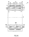
図16は、変圧器10の1次コイルおよび変圧器410の2次コイルを使用した、第5の実施形態における変圧器510の断面図である。図16においては、したがって、図3の場合または図11の場合と同じ参照符号が使用され、詳細な説明は省略される。
FIG. 16 is a cross-sectional view of the
知られている方法で、変圧器は、複数の2次コイルを有してもよい。したがって、図示されていない実施形態においては、各2次コイルのコイルは、変圧器410の原理を使用してコイルを通すのに必要なスロットをその脚においてもつことを条件として、共通の本体に変圧器10の原理および変圧器410に原理を使用して同時に作られてもよい。
In a known manner, the transformer may have a plurality of secondary coils. Thus, in an embodiment not shown, each secondary coil has a common body with a common slot provided that the legs have the necessary slots to pass the coil using the principle of
Claims (9)
1次部分(11)が、強磁性材料で作られた第1の本体、および1次コイル(24、25、26、27;224、225、226、227)を備え、2次部分(12)が、強磁性材料で作られた第2の本体、および2次コイル(28、29、30、31;228、229、230、231)を備え、
第1の本体が、軸線Aの第1の環状スロット(22)および軸線Aの第2の環状スロット(23)を画定し、第1のスロット(22)が、第1の側脚(18;214)、中央脚(19;215)、およびリング(17;213)によって画定され、第2のスロット(23)が、中央脚(19;215)、第2の側脚(20;216)、およびリング(17;213)によって画定され、
1次コイルが、相Uに対応する第1のスロット(22)に軸線Aの第1のトロイダルコイル(24;234)、第1のスロット(22)に軸線Aの第2のトロイダルコイル(25;235)、第2のスロット(23)に軸線Aの第3のトロイダルコイル(26;226)、および相Wに対応する第2のスロット(23)に軸線Aの第4のトロイダルコイル(27;227)を備え、相Vに対応する第2のコイル(25;225)および第3のコイル(26;226)が、直列に接続されている、三相変圧器であって、
第2のコイル(25;225)および第3のコイル(26;236)の巻回および接続方向が、第2のコイル(25;225)および第3のコイル(26;226)に流れる電流(Ibp)について、第2のコイル(25;225)の第1の磁位(−Pb)に対応し、第3のコイル(26;226)の第1の磁位(−Pb)と逆の第2の磁位(Pb)に対応する、三相変圧器。 A three-phase transformer (10, 110, 210, 310, 510) having a primary part (11; 12) and a secondary part (12; 11),
The primary part (11) comprises a first body made of a ferromagnetic material and a primary coil (24, 25, 26, 27; 224, 225, 226, 227), the secondary part (12) Comprises a second body made of a ferromagnetic material and a secondary coil (28, 29, 30, 31; 228, 229, 230, 231),
The first body defines a first annular slot (22) of axis A and a second annular slot (23) of axis A, the first slot (22) being a first side leg (18; 214), the central leg (19; 215), and the ring (17; 213), the second slot (23) is connected to the central leg (19; 215), the second side leg (20; 216), And a ring (17; 213),
The primary coil has a first toroidal coil (24; 234) with an axis A in a first slot (22) corresponding to phase U and a second toroidal coil (25 with an axis A in a first slot (22). 235), a third toroidal coil (26; 226) of axis A in the second slot (23), and a fourth toroidal coil (27 of axis A in the second slot (23) corresponding to phase W) (27); 227), a three-phase transformer, wherein a second coil (25; 225) and a third coil (26; 226) corresponding to phase V are connected in series,
The winding and connecting direction of the second coil (25; 225) and the third coil (26; 236) is determined by the current flowing through the second coil (25; 225) and the third coil (26; 226) ( I bp ) corresponds to the first magnetic potential (−Pb) of the second coil (25; 225) and is opposite to the first magnetic potential (−Pb) of the third coil (26; 226). A three-phase transformer corresponding to the second magnetic potential (Pb).
2次コイルが、相Uに対応する第1の2次スロット(34)に軸線Aの第1のトロイダル2次コイル(28)、第1の2次スロット(34)に軸線Aの第2のトロイダル2次コイル(29)、第2の2次スロット(35)に軸線Aの第3のトロイダル2次コイル(30)、および相Wに対応する第2の2次ノッチ(35)に軸線Aの第4のトロイダル2次コイル(31)を備え、相Vに対応する第2の2次コイル(29)および第3の2次コイル(30)が、直列に接続されている、請求項2に記載の変圧器(10、110)。 The second body defines a first annular secondary slot (34) of axis A and a second annular secondary slot (35) of axis A, the first secondary slot (34) being A secondary secondary leg (14), a secondary central leg (15), and a secondary ring (13) defined by a second secondary slot (35), the secondary central leg (15), the second Secondary leg (16) and secondary ring (13)
A secondary coil has a first toroidal secondary coil (28) of axis A in a first secondary slot (34) corresponding to phase U and a second of axis A in a first secondary slot (34). Toroidal secondary coil (29), second secondary slot (35) to third toroidal secondary coil (30) of axis A, and second secondary notch (35) corresponding to phase W to axis A And a second secondary coil (29) and a third secondary coil (30) corresponding to phase V are connected in series. The transformer (10, 110) according to.
2次コイルが、直列に接続された1つまたは複数の2次コイル(424c、429c、431c)を備え、前記2次コイル(429c)が、前記2次脚に巻回されて、前記2次脚におけるスロット(436)の中を通過する、請求項2に記載の変圧器(510)。 The second body defines a first annular secondary slot (34) of axis A and a second annular secondary slot (35) of axis A, the first secondary slot (34) being A secondary secondary leg (14), a secondary central leg (15), and a secondary ring (13) defined by a second secondary slot (36), the secondary central leg (15), the second Secondary leg (16) and secondary ring (13)
The secondary coil includes one or more secondary coils (424c, 429c, 431c) connected in series, and the secondary coil (429c) is wound around the secondary leg, and the secondary coil The transformer (510) of claim 2, wherein the transformer (510) passes through a slot (436) in the leg.
Applications Claiming Priority (3)
| Application Number | Priority Date | Filing Date | Title |
|---|---|---|---|
| FR1254291 | 2012-05-10 | ||
| FR1254291A FR2990557B1 (en) | 2012-05-10 | 2012-05-10 | THREE-PHASE MAGNETICALLY LEVER TRANSFORMER |
| PCT/FR2013/050984 WO2013167828A1 (en) | 2012-05-10 | 2013-05-03 | Three-phase rotary transformer having a magnetic shell |
Publications (2)
| Publication Number | Publication Date |
|---|---|
| JP2015519747A true JP2015519747A (en) | 2015-07-09 |
| JP2015519747A5 JP2015519747A5 (en) | 2016-06-23 |
Family
ID=48534431
Family Applications (1)
| Application Number | Title | Priority Date | Filing Date |
|---|---|---|---|
| JP2015510856A Withdrawn JP2015519747A (en) | 2012-05-10 | 2013-05-03 | Magnetic shield three-phase rotary transformer |
Country Status (9)
| Country | Link |
|---|---|
| US (1) | US9607758B2 (en) |
| EP (1) | EP2847772A1 (en) |
| JP (1) | JP2015519747A (en) |
| CN (1) | CN104471658A (en) |
| BR (1) | BR112014027880A2 (en) |
| CA (1) | CA2872718A1 (en) |
| FR (1) | FR2990557B1 (en) |
| RU (1) | RU2014149340A (en) |
| WO (1) | WO2013167828A1 (en) |
Families Citing this family (6)
| Publication number | Priority date | Publication date | Assignee | Title |
|---|---|---|---|---|
| FR2990559B1 (en) * | 2012-05-10 | 2015-05-01 | Hispano Suiza Sa | THREE-PHASE TRANSFORMER MAGNETICALLY WITH THREE MAGNETIC CORES |
| FR3059043B1 (en) | 2016-11-18 | 2018-12-14 | Safran Aircraft Engines | TURBOMACHINE HAVING A THREE PHASE POWER SUPPLY TRANSDUCER OF ELECTRIC DEFROSTING ELEMENTS |
| CN109038993A (en) * | 2018-09-15 | 2018-12-18 | 天津大学 | A kind of all-in-one machine of integrated threephase alternator, transformer |
| CN109767902B (en) * | 2019-01-29 | 2021-05-04 | 河海大学 | High-power high-frequency rotating power electronic transformer |
| RU191500U1 (en) * | 2019-05-15 | 2019-08-08 | Федеральное государственное бюджетное образовательное учреждение высшего образования "Комсомольский-на-Амуре государственный университет" (ФГБОУ ВО "КнАГУ") | ROTATING MAGNETIC FIELD TRANSFORMER |
| FR3103308B1 (en) | 2019-11-20 | 2021-10-08 | Safran Aircraft Engines | Rotary transformer and rotating machine comprising such a rotary transformer |
Family Cites Families (16)
| Publication number | Priority date | Publication date | Assignee | Title |
|---|---|---|---|---|
| CA2109652A1 (en) * | 1992-11-25 | 1994-05-26 | Richard J. Becker | Rotary transformer |
| US5608771A (en) * | 1995-10-23 | 1997-03-04 | General Electric Company | Contactless power transfer system for a rotational load |
| JP2001015363A (en) * | 1999-04-28 | 2001-01-19 | Tokin Corp | Noncontact-type transformer |
| DE19953583C1 (en) * | 1999-11-08 | 2001-12-06 | Dieter Seifert | Rotary transformer inductive coupling for asynchronous electrical machine has stationary ferromagnetic primary and ferromagnetic secondary attached to rotor for transfer of slip load |
| DE10203651B4 (en) * | 2002-01-30 | 2004-04-01 | Aloys Wobben | exchangers |
| US7868723B2 (en) * | 2003-02-26 | 2011-01-11 | Analogic Corporation | Power coupling device |
| US7545056B2 (en) * | 2003-05-27 | 2009-06-09 | Pratt & Whitney Canada Corp. | Saturation control of electric machine |
| DE202004016751U1 (en) * | 2004-10-28 | 2005-01-27 | Pro-Micron Gmbh & Co. Kg Modular Systems | Transponder system for non-contact inductive power transmission transfers power from a static side with a reading-coil on a stator onto a rotating side with a transponder coil on a spindle |
| CN1933294A (en) * | 2005-09-12 | 2007-03-21 | 丁振荣 | Brushless non-slip ring AC asynchronous and synchronous electric machine with rotor winding as armature winding |
| FR2892848B1 (en) * | 2005-10-27 | 2009-12-25 | Centre Nat Etd Spatiales | ROTATING TRANSFORMER |
| US7197113B1 (en) * | 2005-12-01 | 2007-03-27 | General Electric Company | Contactless power transfer system |
| US7439713B2 (en) * | 2006-09-20 | 2008-10-21 | Pratt & Whitney Canada Corp. | Modulation control of power generation system |
| CA2721358C (en) * | 2008-04-14 | 2016-12-20 | Aker Engineering & Technology As | Rotary transformer |
| CH700533A1 (en) * | 2009-03-11 | 2010-09-15 | Alstom Technology Ltd | Rotary transformer to supply the field winding in a dynamoelectric machine. |
| US20110141771A1 (en) * | 2010-12-07 | 2011-06-16 | Karl Kyrberg | Electric power system including power converter and rotary transformer and method of assembling same |
| FR2990556B1 (en) * | 2012-05-09 | 2014-05-30 | Hispano Suiza Sa | THREE-PHASE TRIPHASE ROTATING TRANSFORMER FREE |
-
2012
- 2012-05-10 FR FR1254291A patent/FR2990557B1/en active Active
-
2013
- 2013-05-03 US US14/400,143 patent/US9607758B2/en active Active
- 2013-05-03 EP EP13725414.0A patent/EP2847772A1/en not_active Withdrawn
- 2013-05-03 CA CA2872718A patent/CA2872718A1/en not_active Abandoned
- 2013-05-03 JP JP2015510856A patent/JP2015519747A/en not_active Withdrawn
- 2013-05-03 RU RU2014149340A patent/RU2014149340A/en not_active Application Discontinuation
- 2013-05-03 CN CN201380024572.7A patent/CN104471658A/en active Pending
- 2013-05-03 WO PCT/FR2013/050984 patent/WO2013167828A1/en active Application Filing
- 2013-05-03 BR BR112014027880A patent/BR112014027880A2/en not_active IP Right Cessation
Also Published As
| Publication number | Publication date |
|---|---|
| RU2014149340A (en) | 2016-07-10 |
| CA2872718A1 (en) | 2013-11-14 |
| FR2990557B1 (en) | 2015-05-01 |
| US20150137924A1 (en) | 2015-05-21 |
| WO2013167828A1 (en) | 2013-11-14 |
| EP2847772A1 (en) | 2015-03-18 |
| BR112014027880A2 (en) | 2017-06-27 |
| CN104471658A (en) | 2015-03-25 |
| FR2990557A1 (en) | 2013-11-15 |
| US9607758B2 (en) | 2017-03-28 |
Similar Documents
| Publication | Publication Date | Title |
|---|---|---|
| JP2015519747A (en) | Magnetic shield three-phase rotary transformer | |
| JP6174126B2 (en) | Three-phase rotary transformer with free interlinkage magnetic flux | |
| US7274280B1 (en) | Nine-phase step-up/step-down autotransformer | |
| CN209168896U (en) | Three-phase transformer | |
| US9424987B2 (en) | Three-phase/two-phase rotary transformer including a scott connection | |
| JP6208221B2 (en) | Three-phase / two-phase rotary transformer | |
| JPS60240111A (en) | Transformer | |
| US7750782B1 (en) | Nine-phase autotransformer | |
| JP6247282B2 (en) | Three-phase two-phase fixed transformer with forcibly coupled magnetic flux | |
| US9424978B2 (en) | Magnetically shielded three phase rotary transformer having three magnetic cores | |
| US6456184B1 (en) | Reduced-cost core for an electrical-power transformer | |
| US10217555B2 (en) | Compact inductor | |
| TWI830063B (en) | Three-phase magnetics assembly | |
| KR20150073055A (en) | Power circuit, iron core for scott connected transformer, scott connected transformer and superheated steam generator | |
| JP7365700B2 (en) | variable transformer | |
| US1227415A (en) | Transformer. | |
| WO2011124285A1 (en) | Static electric power converter | |
| JP2022188551A (en) | static induction electric machine | |
| JP6210871B2 (en) | Power circuit | |
| RU89304U1 (en) | MULTI-CHANNEL VOLTAGE STABILIZER | |
| RU2353014C1 (en) | Converter transformer | |
| JPS62205611A (en) | Transformer for three-phase, two-phase conversion |
Legal Events
| Date | Code | Title | Description |
|---|---|---|---|
| A521 | Written amendment |
Free format text: JAPANESE INTERMEDIATE CODE: A523 Effective date: 20160425 |
|
| A621 | Written request for application examination |
Free format text: JAPANESE INTERMEDIATE CODE: A621 Effective date: 20160425 |
|
| A761 | Written withdrawal of application |
Free format text: JAPANESE INTERMEDIATE CODE: A761 Effective date: 20160713 |