JP2015513450A - Valve device - Google Patents
Valve device Download PDFInfo
- Publication number
- JP2015513450A JP2015513450A JP2014556165A JP2014556165A JP2015513450A JP 2015513450 A JP2015513450 A JP 2015513450A JP 2014556165 A JP2014556165 A JP 2014556165A JP 2014556165 A JP2014556165 A JP 2014556165A JP 2015513450 A JP2015513450 A JP 2015513450A
- Authority
- JP
- Japan
- Prior art keywords
- valve device
- pulse tube
- plunger
- edge
- pulse
- Prior art date
- Legal status (The legal status is an assumption and is not a legal conclusion. Google has not performed a legal analysis and makes no representation as to the accuracy of the status listed.)
- Withdrawn
Links
Images


Classifications
-
- B—PERFORMING OPERATIONS; TRANSPORTING
- B01—PHYSICAL OR CHEMICAL PROCESSES OR APPARATUS IN GENERAL
- B01D—SEPARATION
- B01D46/00—Filters or filtering processes specially modified for separating dispersed particles from gases or vapours
- B01D46/02—Particle separators, e.g. dust precipitators, having hollow filters made of flexible material
- B01D46/04—Cleaning filters
-
- B—PERFORMING OPERATIONS; TRANSPORTING
- B01—PHYSICAL OR CHEMICAL PROCESSES OR APPARATUS IN GENERAL
- B01D—SEPARATION
- B01D46/00—Filters or filtering processes specially modified for separating dispersed particles from gases or vapours
- B01D46/66—Regeneration of the filtering material or filter elements inside the filter
- B01D46/70—Regeneration of the filtering material or filter elements inside the filter by acting counter-currently on the filtering surface, e.g. by flushing on the non-cake side of the filter
- B01D46/71—Regeneration of the filtering material or filter elements inside the filter by acting counter-currently on the filtering surface, e.g. by flushing on the non-cake side of the filter with pressurised gas, e.g. pulsed air
-
- B—PERFORMING OPERATIONS; TRANSPORTING
- B01—PHYSICAL OR CHEMICAL PROCESSES OR APPARATUS IN GENERAL
- B01D—SEPARATION
- B01D46/00—Filters or filtering processes specially modified for separating dispersed particles from gases or vapours
- B01D46/42—Auxiliary equipment or operation thereof
- B01D46/4272—Special valve constructions adapted to filters or filter elements
Abstract
圧縮ガスのパルスを提供して、布製フィルタ(1)に設けられた布製フィルタバグ(6)を清浄化するために適合された、布製フィルタ(1)に用いられる弁装置(9)。この弁装置(9)は、パルス管(13)の第1の端部(16)の縁部(15)に対して運動可能なプランジャ(12)を有している。弁装置(9)が閉鎖されている場合には、プランジャ(12)が、パルス管(13)の第1の端部(16)の縁部(15)に接触していて、パルス管(13)の内部(13a)への圧縮ガスの流れを遮断している。プランジャ(12)および/またはパルス管(13)の第1の端部(16)の縁部(15)には、シール材料から成るシール部分(19)が配置されている。A valve device (9) used for a fabric filter (1) adapted to provide a pulse of compressed gas and to clean the fabric filter bug (6) provided in the fabric filter (1). This valve device (9) has a plunger (12) movable relative to the edge (15) of the first end (16) of the pulse tube (13). When the valve device (9) is closed, the plunger (12) is in contact with the edge (15) of the first end (16) of the pulse tube (13) and the pulse tube (13 The flow of the compressed gas to the inside (13a) is cut off. On the edge (15) of the first end (16) of the plunger (12) and / or the pulse tube (13), a sealing part (19) of sealing material is arranged.
Description
本発明は、圧縮ガスのパルスを提供して、つまり、衝撃を与えて少なくとも1つの布製フィルタバグを清浄化するための弁装置に関する。 The present invention relates to a valve arrangement for providing a pulse of compressed gas, i.e. for applying an impact to clean at least one fabric filter bug.
背景技術
布製フィルタは、ガス清浄化システムに頻繁に使用される。このような布製フィルタは、典型的に多数のフィルタバグを有している。これらのフィルタバグでは、ガスが進入するのに対して、このガス内で同伴された粒子または粉塵は濾布よって捕捉され、最終的にフィルタバグの外側に付着する。しばらくの間、このような布製フィルタが使用されると、フィルタバグの外面が多少なりとも粒子または粉塵で覆われ、その後、布を通るガスの適切な通路を維持するために、フィルタバグが清浄化されなければならない。フィルタバグの清浄化は、このフィルタバグの内側に圧縮空気のパルスを提供して布を急速に伸長させ、これによって、フィルタバグの外面に付着している粒子を払い落とすことによって行うことができる。フィルタバグに圧縮空気のパルスを提供することができるようにするためには、弁装置が設けられてよい。
BACKGROUND ART Fabric filters are frequently used in gas cleaning systems. Such fabric filters typically have numerous filter bugs. In these filter bugs, gas enters, whereas particles or dust entrained in the gas are trapped by the filter cloth and eventually adhere to the outside of the filter bug. When such a fabric filter is used for a while, the outer surface of the filter bug is covered with some particles or dust, and then the filter bug is cleaned to maintain a proper passage of gas through the fabric. Must be made. Cleaning the filter bug can be done by providing a pulse of compressed air inside the filter bug to cause the fabric to stretch rapidly, thereby removing particles adhering to the outer surface of the filter bug. . In order to be able to provide a pulse of compressed air to the filter bag, a valve device may be provided.
欧州特許出願公開第0678177号明細書には、汚染されたガスを清浄化するための濾過設備に設けられた鉛直に配置された袋状のフィルタバグに圧縮空気パルスを接続するための弁装置が開示されている。この弁装置が適切に機能するとしても、場合によっては、まだ改良が必要となる。 European Patent Application 0 678 177 discloses a valve device for connecting a compressed air pulse to a vertically arranged bag-like filter bag provided in a filtration facility for cleaning contaminated gas. It is disclosed. Even if this valve device functions properly, it may still need improvement.
概要
本願において図示した1つの態様によれば、圧縮ガスのパルスを提供して少なくとも1つの布製フィルタバグを清浄化するための、布製フィルタに用いられる弁装置が提供されている。この弁装置は、プランジャと、第1の端部および第2の端部を備えたパルス管とを有している。プランジャとパルス管とは、弁装置の開放状態と閉鎖状態との間で互いに関連して運動可能である。プランジャは、閉鎖状態では、パルス管の第1の端部の縁部に接触して、パルス管の第1の端部を閉鎖するように配置されており、プランジャは、開放状態では、パルス管の第1の端部内へ圧縮ガスが進入するのを許容して、パルス管の第2の端部から放出された圧縮ガスのパルスを提供するように配置されている。プランジャおよびパルス管の第1の端部の縁部のうちの少なくとも一方に、シール材料から形成されたシール部分が配置されている。これによって、弁装置の閉鎖状態でプランジャとパルス管の第1の端部の縁部との間に封止が提供されている。
SUMMARY In accordance with one aspect illustrated herein, a valve device for use with a fabric filter is provided for providing a pulse of compressed gas to clean at least one fabric filter bug. The valve device has a plunger and a pulse tube having a first end and a second end. The plunger and the pulse tube are movable relative to each other between the open state and the closed state of the valve device. The plunger is arranged to contact the edge of the first end of the pulse tube in the closed state and close the first end of the pulse tube, and the plunger is in the open state to the pulse tube. Is arranged to provide a pulse of compressed gas released from the second end of the pulse tube, allowing the compressed gas to enter into the first end of the pulse tube. At least one of the plunger and the edge of the first end of the pulse tube is disposed with a seal portion formed from a seal material. This provides a seal between the plunger and the edge of the first end of the pulse tube in the closed state of the valve device.
本願において図示した別の態様によれば、弁装置を有する布製フィルタ清浄化システムが提供されている。 According to another aspect illustrated herein, a fabric filter cleaning system having a valve device is provided.
上述した特徴および別の特徴を以下の図面によって例示し、詳細に説明する。 The above described and other features are illustrated and described in detail in the following figures.
好適な実施の形態の詳細な説明
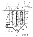
図1は、布製フィルタ1の断面を側方から見た概略図である。この布製フィルタ1はハウジング2を有している。このハウジング2の内部2aへのガス入口は、粒子状材料、たとえば粉塵が除去されるようになっているガスのためのダクト3である。このダクト3は、接続部3aに流体接続されているかまたはハウジング2の下側の部分2bと一体に形成されている。内部2aからの清浄ガス出口はダクト4である。このダクト4は、接続部4aに接続されているかまたはハウジング2の上側の部分2cと一体に形成されている。ハウジング2の内部2aで両ダクト3,4の間には、水平なプレート5が配置されている。このプレート5に設けられた開口5a内には、引き伸ばされた管状の布製バグ6の形態の多数の布製濾過装置が取外し可能に取り付けられている。典型的には、1つの布製フィルタ1が2〜20000個のこのような布製バグ6を有していてよい。運転中には、粉塵粒子を含んだガス、たとえば燃焼設備からの煙道ガスが、ダクト3を介してハウジング2の下側の部分2bに進入する。その後、ガスがバグ6の布を通過して、このバグ6の内部6aに進入するのに対して、粉塵粒子はバグ6の外面6bに捕集される。その後、清浄ガスが、バグ6の内部6aからプレート5の開口5aを通流して、ダクト4を介して布製フィルタ1から進出する。
DETAILED DESCRIPTION OF PREFERRED EMBODIMENTS FIG. 1 is a schematic view of a cross section of a fabric filter 1 as viewed from the side. The fabric filter 1 has a housing 2. The gas inlet to the interior 2a of the housing 2 is a
時として、捕集された粉塵粒子をバグ6の外面6bから除去することが必要となる。布製フィルタ1の上側の部分2cには、パルスガス用ダクト7が配置されている。このパルスガス用ダクト7は、バグ6が取り付けられた開口5aに対して、それぞれ1つのパルスノズル8を備えている。パルスガス用ダクト7は、圧縮ガス、たとえば与圧空気の供給部に流体接続された弁装置9に接続されている。圧縮ガスは、典型的には、バグ6の外面6bを清浄化するために適した2〜6barの絶対圧を有している。
Sometimes it is necessary to remove the collected dust particles from the outer surface 6b of the
たとえば、粉塵粒子の前回の除去以来、所定の時間が経過したかまたは両ダクト3,4の間での測定時にガス流における所定の圧力損失が生じたことに基づき、捕集された粉塵粒子をバグ6の外面6bから除去することが適当であることが決定されると、短期間、典型的には150〜500msの期間、弁装置9が開放される。結果として、この短期間の弁装置9の開放によって、短パルスのガスが、パルス管13の内部13aを通流して、流体接続されたパルスガス用ダクト7と、流体接続された各パルスノズル8とに到達し、バグ6の内部6aに流入する。このようなパルスのガスの結果として、バグ6が急速に膨張し、その外面6bに捕集された粉塵の、全てではないにせよ、大部分が解放されるようになっている。このような解放された粉塵は、ハウジング2のホッパ10内に下向きに落下する。したがって、ダクト7と、ノズル8と、弁装置9とが、布製フィルタ1の清浄化システムを形成している。時として、粉塵はホッパ10から、たとえばスクリュ11によって除去される。
For example, since a predetermined time has elapsed since the previous removal of the dust particles or a predetermined pressure loss in the gas flow has occurred during the measurement between the
図2には、弁装置9の実施の形態の一例が概略的に示してある。この弁装置9は、プランジャ12とパルス管13とを有している。プランジャ12は、弁ハウジング14の内側において弁装置9の開放状態と閉鎖状態との間で運動可能である。閉鎖状態では、図2に示したように、プランジャ12が、パルス管13の、開放する第1の端部16の縁部15に接触していて、これによって、パルス管13の第1の端部16を閉鎖しているかもしくは閉塞しているので、パルス管13の第1の端部16を取り囲む圧力タンク17内に存在する圧縮ガス、たとえば圧縮空気が、パルス管13に進入することができず、その内部13aを通流することができない。開放状態では、プランジャ12が変位させられていて、開放した第1の端部16の縁部15に接触しておらず、圧力タンク17内の圧縮ガスがパルス管13に進入することができ、内部13aを通流して、パルスガス用ダクト7と、流体接続された各パルスノズル8とに到達することができる。圧縮ガスの、弁装置9を急速に開閉することによって得られるパルスは、パルス管13の、パルスガス用ダクト7に流体接続された第2の端部18から放出され、引き続き、ノズル8に到達して、バグ6を清浄化する。
FIG. 2 schematically shows an embodiment of the valve device 9. The valve device 9 has a
また、プランジャ12に接触しかつプランジャ12から離反するように運動可能となるようにパルス管13の縁部15を配置することが可能であってもよいし、実際には、パルス管13および/またはパルス管13の縁部15とプランジャ12との両方が、互いに関して運動可能であってもよい。言い換えると、パルス管13の縁部15とプランジャ12とが圧力タンク17内で協働して、圧縮ガスをパルス管13内に流入させるための通路を開閉する。プランジャ12とパルス管13とは、硬質の材料、たとえば鋼またはポリアミド材料から製造されていてもよいし、これらの材料の硬さに類似もしくは同程度の硬さを有していて、圧縮ガスのパルスを提供するために弁装置9が開閉される際のプランジャ12とパルス管13との間の繰り返される衝突に耐えることができる別種のあらゆる適切な材料から製造されていてもよい。パルス管13とプランジャ12とは、同じ材料から製造されていてもよいし、異なる材料から製造されていてもよい。いずれにせよ、プランジャ12とパルス管13との硬さおよび非変形性は、プランジャ12とパルス管13の第1の端部16の縁部15との形成において誤差が小さいことを意味している。圧縮ガスパルスを効率よく提供しつつ、圧力損失を最小限に抑えることができるようにするためには、弁装置9がその閉鎖状態にある場合に、あらゆるガス漏れが最小限に抑えられていることが望ましい。
It may also be possible to arrange the
図3a〜図3fにおいて詳しく説明する種々異なる実施の形態では、シール材料から成る1つ以上のシール部分19が、プランジャ12または縁部15に存在しているかもしくはプランジャ12および縁部15に存在している。シール材料は、プランジャ12とパルス管13とを形成する材料よりも変形可能であってよく、これによって、弁装置9の閉鎖状態でのパルス管13の第1の端部16の閉鎖が改善される一方、同時に誤差要求が緩和される。なぜならば、シール部分19がプランジャ12と縁部15との接触面におけるあらゆる欠陥を補償することができるからである。弁装置9の閉鎖が改善されると、圧縮ガスの漏れを減少させることができ、さらに、圧縮ガスを布製フィルタ清浄化システムに供給するためのコストが削減される。
In different embodiments, which are described in detail in FIGS. 3 a-3 f, one or more sealing
プランジャ12が縁部15に接触している場合には、プランジャ12または縁部15もしくはプランジャ12および縁部15に存在しているシール部分19がある程度変形させられてよく、これによって、閉鎖状態での弁装置9の気密性が改善される。シール部分19の変形は可能である。なぜならば、このシール部分19がプランジャ12およびパルス管13の材料よりも軟質であるかまたは、言い換えると、プランジャ12およびパルス管13の硬さよりも少ない変形硬さを有しているからである。シール部分19を製造するための適切な材料は、ポリマ材料、たとえばプラスチックを含んでいてもよいし、適切な特性を有する別種の材料、たとえば天然ゴムまたは合成ゴムを含んでいてもよい。さらに、シール材料は、やや弾性的な特性を有していてよい。
If the
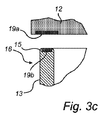
図3a〜図3fには、プランジャ12が縁部15に接触する範囲A内のシール部分19の配置形態の多数の無制限の例がより詳しく示してある。明瞭な図示のために、ここでは、弁装置9が開放状態で示してある。
3a to 3f show in more detail a number of unlimited examples of the arrangement of the sealing
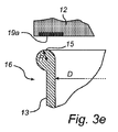
図3aでは、シール部分19が、パルス管13の第1の端部16の縁部15に配置されている。図3bおよび図3eでは、シール部分19が、プランジャ12に配置されている。図3d〜図3fでは、縁部15が、この縁部15に対して所定の曲率半径Rを備えて、より丸み付けられた断面形状を有する「ベルマウス(ラッパ口)」の形で形成されている。このベルマウスの丸み付けられた断面形状によって、弁装置9がその開放状態にある場合に、パルス管13の、開放した第1の端部16への圧縮ガスの流れが容易になる。曲率半径Rは5〜15mmであってもよいし、R>0.1×Dとして定義されてもよい。なお、Dは、パルス管13の直径である。
In FIG. 3 a, the sealing
図3cおよび図3dでは、プランジャ12に第1のシール部分19aが存在しており、縁部15に第2のシール部分19bが存在している。図3fでは、シール部分19がプランジャ12とベルマウス状の縁部15とに存在しており、より詳細には、本質的にベルマウス形状全体がシール材料から形成されている。また、たとえば、図3dおよび図3fに示した形態をベースとして、シール材料から成る部分19がベルマウス状の縁部15にしか存在しておらず、プランジャ12にはシール部分19が存在していない別の変化形態も可能である。
3c and 3d, the
付言しておくと、シール材料から成る部分がパルス管縁部に配置されることによって、パルス管入口に所望の幾何学形状を提供することが容易になり、さらに、この幾何学形状は、弁装置9が開放している場合、パルス管内に流入する圧縮ガスに対する流れ特性を改善することができる。 In addition, the portion of the sealing material located at the pulse tube edge facilitates providing the desired geometry at the pulse tube inlet, and the geometry is When the device 9 is open, the flow characteristics for the compressed gas flowing into the pulse tube can be improved.
シール部分19がプランジャ12に配置されている場合には、このプランジャ12を置き換えるかまたは変更することが極めて簡単であるので、本発明の実施の形態が既存の装置に簡単に提供される。
If the sealing
最後に、シール部分19がプランジャ12と縁部15とに配置されている場合には、2つの位置の間でそれぞれ異なるシール材料を組み合わせることが可能となり、さらに、これらのシール材料は、より効率のよい封止さえ提供することができる。
Finally, if the sealing
シール材料から成るシール部分19,19a,19bは、プランジャ12および/または縁部15の材料に少なくとも部分的に組み込まれていてもよいし、プランジャ12および/または縁部15の材料と一体に製造されていてもよい。縁部15がベルマウス形状を有している場合には、シール部分19;19bがベルマウス状の縁部15に少なくとも部分的に組み込まれていてよい。プランジャ12および/または縁部15の材料へのシール部分19の組込みまたは部分的な組込みは、シール部分19の確実な取付けを提供する。これによって、圧縮ガスのパルスをパルスガス用ダクト7を介してノズル8に供給するために、弁装置9が繰返し開閉される場合に発生する、プランジャ12とパルス管13との間での複数回の繰り返される衝突に耐えることが可能となる。
The sealing
要するに、本発明に係る弁装置9は、圧縮ガスのパルスを提供して布製フィルタ1内の布製フィルタバグ6を清浄化するために適合された弁装置9におけるシール性を改善している。弁装置9は、パルス管13の第1の端部16の縁部15に対して運動可能なプランジャ12を有している。弁装置9が閉鎖されている場合には、プランジャ12がパルス管13の第1の端部16の縁部15に接触していて、したがって、パルス管13の内部13aへの圧縮ガスの流れを遮断している。プランジャ12および/またはパルス管13の第1の端部16の縁部15には、シール材料から成るシール部分19が配置されている。こうして、パルス管13内への圧縮ガスの漏れが減少させられ、さらに、布製フィルタ1に用いられる清浄化装置のコストが削減される。同時に、プランジャ12とパルス管13の第1の端部16の縁部15との間で誤差要求が緩和され、シール材料が、その弾性的なかつ/または変形可能な特性のため、プランジャ12とパルス管13との接触面の形状におけるあらゆる凹凸を埋め合わせることができる。このことは、さらに、弁装置9の製造におけるコスト削減を意味している。
In short, the valve device 9 according to the present invention improves the sealing performance of the valve device 9 adapted to provide a pulse of compressed gas to clean the
本発明を多数の好適な実施の形態に関して説明したにもかかわらず、当業者によって自明であるように、本発明の範囲から逸脱することなしに、種々異なる変更が行われてもよいし、そのエレメントの代わりに、同等のものが用いられてもよい。さらに、本発明の主要な範囲から逸脱することなしに、特殊な状況または材料を本発明の教示に適合させるために、多くの変更が行われてもよい。したがって、本発明は、この本発明を実施するために考慮された最良の形態として記載した特殊な実施の形態に限定されるものではなく、本発明は、添付した特許請求の範囲に属する全ての実施の形態を包括することが意図されている。さらに、第1、第2等の術語の使用は、決して順序または重要性を示すものではなく、むしろ、第1、第2等の用語は、ある1つのエレメントを別のエレメントと区別するために使用されるものである。 Although the present invention has been described in terms of a number of preferred embodiments, various modifications may be made without departing from the scope of the invention, as will be apparent to those skilled in the art. An equivalent may be used instead of the element. In addition, many modifications may be made to adapt a particular situation or material to the teachings of the invention without departing from the main scope thereof. Accordingly, the present invention is not limited to the specific embodiment described as the best mode contemplated for carrying out the invention, and the invention is not limited to the appended claims. It is intended to encompass embodiments. Furthermore, the use of the terms first, second, etc. is by no means implied in order or importance; rather, terms such as first, second, etc. are used to distinguish one element from another. It is what is used.
Claims (15)
Applications Claiming Priority (3)
| Application Number | Priority Date | Filing Date | Title |
|---|---|---|---|
| EP12154678.2A EP2626122A1 (en) | 2012-02-09 | 2012-02-09 | Valve arrangement |
| EP12154678.2 | 2012-02-09 | ||
| PCT/IB2013/050842 WO2013118036A1 (en) | 2012-02-09 | 2013-01-31 | Valve arrangement |
Publications (1)
| Publication Number | Publication Date |
|---|---|
| JP2015513450A true JP2015513450A (en) | 2015-05-14 |
Family
ID=47884443
Family Applications (1)
| Application Number | Title | Priority Date | Filing Date |
|---|---|---|---|
| JP2014556165A Withdrawn JP2015513450A (en) | 2012-02-09 | 2013-01-31 | Valve device |
Country Status (8)
| Country | Link |
|---|---|
| US (1) | US20140318087A1 (en) |
| EP (1) | EP2626122A1 (en) |
| JP (1) | JP2015513450A (en) |
| CN (1) | CN104114257A (en) |
| AU (1) | AU2013217250A1 (en) |
| CA (1) | CA2864210A1 (en) |
| IN (1) | IN2014DN07186A (en) |
| WO (1) | WO2013118036A1 (en) |
Cited By (1)
| Publication number | Priority date | Publication date | Assignee | Title |
|---|---|---|---|---|
| JP2022046493A (en) * | 2015-11-03 | 2022-03-23 | スプレイング システムズ カンパニー | Apparatus and method for spray drying |
Families Citing this family (6)
| Publication number | Priority date | Publication date | Assignee | Title |
|---|---|---|---|---|
| US10343098B2 (en) | 2013-05-13 | 2019-07-09 | General Electric Company | Cleaning valve with dampening mechanism |
| EP2913091B1 (en) * | 2014-02-26 | 2018-07-18 | General Electric Technology GmbH | Method for cleaning a fabric filter system |
| EP3130829B1 (en) * | 2015-08-12 | 2018-08-15 | General Electric Technology GmbH | Valve |
| CN206984426U (en) | 2016-06-14 | 2018-02-09 | Jvm有限公司 | Drug packages equipment |
| US11092980B2 (en) | 2016-11-16 | 2021-08-17 | General Electric Technology Gmbh | Pulse valve with pressure vessel penetration |
| CN110538525B (en) * | 2019-09-11 | 2021-11-02 | 江苏亿金环保科技有限公司 | Bag-type dust collector |
Family Cites Families (13)
| Publication number | Priority date | Publication date | Assignee | Title |
|---|---|---|---|---|
| US926400A (en) * | 1907-06-14 | 1909-06-29 | Patrick J Freaney | Valve. |
| DE3933169A1 (en) * | 1989-10-04 | 1991-04-18 | Messerschmitt Boelkow Blohm | SEAT VALVE |
| DE4030086C1 (en) * | 1990-09-21 | 1991-12-12 | Herbert 7853 Steinen De Huettlin | |
| SE468721B (en) | 1991-07-04 | 1993-03-08 | Flaekt Ab | VALVE DEVICE FOR GENERATING SHORT-TERM PRESSURE PULSES EXAMPLE FOR BLEASING BASIC FILTER ELEMENTS |
| JP3533348B2 (en) * | 1999-09-16 | 2004-05-31 | Smc株式会社 | Dust collector valve |
| NL1013371C2 (en) * | 1999-10-22 | 2001-04-24 | Asco Controls Bv | Apparatus and method for cleaning a filter. |
| JP4242171B2 (en) * | 2003-02-21 | 2009-03-18 | メタウォーター株式会社 | Filter and filter module |
| WO2005079954A1 (en) * | 2004-02-17 | 2005-09-01 | Donaldson Company, Inc. | Air cleaner arrangements; serviceable filter elements; and, methods |
| CN200961711Y (en) * | 2006-10-11 | 2007-10-17 | 江苏科林集团有限公司 | Air cylinder type pulse valve |
| DE102007017091A1 (en) * | 2007-04-10 | 2008-10-16 | Mahle International Gmbh | Ring filter element |
| CN101293158B (en) * | 2008-06-12 | 2011-01-26 | 武汉华保技术工程有限公司 | Impulse magnetic valve for removing dust and clearing ash |
| CN101879395B (en) * | 2010-02-09 | 2012-08-22 | 中山市君禾机电设备有限公司 | Filter element component and dust removal device therewith |
| IT1401291B1 (en) * | 2010-05-27 | 2013-07-18 | Messina | VALVE AND CLEANING SYSTEM FOR DUST DUST |
-
2012
- 2012-02-09 EP EP12154678.2A patent/EP2626122A1/en not_active Withdrawn
-
2013
- 2013-01-31 CN CN201380008903.8A patent/CN104114257A/en active Pending
- 2013-01-31 JP JP2014556165A patent/JP2015513450A/en not_active Withdrawn
- 2013-01-31 IN IN7186DEN2014 patent/IN2014DN07186A/en unknown
- 2013-01-31 WO PCT/IB2013/050842 patent/WO2013118036A1/en active Application Filing
- 2013-01-31 AU AU2013217250A patent/AU2013217250A1/en not_active Abandoned
- 2013-01-31 CA CA2864210A patent/CA2864210A1/en not_active Abandoned
-
2014
- 2014-07-10 US US14/328,029 patent/US20140318087A1/en not_active Abandoned
Cited By (1)
| Publication number | Priority date | Publication date | Assignee | Title |
|---|---|---|---|---|
| JP2022046493A (en) * | 2015-11-03 | 2022-03-23 | スプレイング システムズ カンパニー | Apparatus and method for spray drying |
Also Published As
| Publication number | Publication date |
|---|---|
| EP2626122A1 (en) | 2013-08-14 |
| IN2014DN07186A (en) | 2015-04-24 |
| US20140318087A1 (en) | 2014-10-30 |
| CA2864210A1 (en) | 2013-08-15 |
| AU2013217250A1 (en) | 2014-08-14 |
| CN104114257A (en) | 2014-10-22 |
| WO2013118036A1 (en) | 2013-08-15 |
Similar Documents
| Publication | Publication Date | Title |
|---|---|---|
| JP2015513450A (en) | Valve device | |
| EP2998628B1 (en) | Valve with small vessel penetration diameter | |
| JP2015509842A (en) | Filter housing and filter unit | |
| JP2015160210A (en) | Fabric filter system and method for cleaning the fabric filter system | |
| EP2803886B1 (en) | Cleaning valve with dampening mechanism | |
| CN108136428A (en) | For the cleaning of needle nozzle | |
| US9993762B2 (en) | Quiet pulse valve | |
| US759141A (en) | Pneumatic renovator. | |
| JP2007085547A (en) | Quick connecting pipe joint with filter | |
| JP2023501887A (en) | Filter device and method for cleaning filter element of filter device | |
| KR101106073B1 (en) | Reverse-cleaning apparatus of a filter for a high pressure dust collector | |
| US10092872B2 (en) | Valve with small vessel penetration diameter | |
| CN113573793B (en) | Cleaning device and cleaning method for dust collector | |
| WO2018194494A1 (en) | System for industrial gas dedusting using baghouses | |
| KR20150080968A (en) | Control device of air supplying line applied in filtering device | |
| JP4747021B2 (en) | Filter device | |
| WO2018194491A1 (en) | Industrial gas dedusting line | |
| JP7462340B2 (en) | Filter Backwash System | |
| RU76246U1 (en) | HOSE FILTER | |
| RU76247U1 (en) | HOSE FILTER | |
| CN107923549A (en) | Valve | |
| JP2016010793A (en) | Air cleaning device | |
| JP6484458B2 (en) | Filter cleaning device and filter cleaning method for air cleaning device | |
| RU2603655C1 (en) | Filter with impulse regeneration | |
| EP3031508A2 (en) | The louver regeneration system for horizontal bag filter |
Legal Events
| Date | Code | Title | Description |
|---|---|---|---|
| A761 | Written withdrawal of application |
Free format text: JAPANESE INTERMEDIATE CODE: A761 Effective date: 20150617 |