JP2015512788A - Insulation for casting articles - Google Patents
Insulation for casting articles Download PDFInfo
- Publication number
- JP2015512788A JP2015512788A JP2015505862A JP2015505862A JP2015512788A JP 2015512788 A JP2015512788 A JP 2015512788A JP 2015505862 A JP2015505862 A JP 2015505862A JP 2015505862 A JP2015505862 A JP 2015505862A JP 2015512788 A JP2015512788 A JP 2015512788A
- Authority
- JP
- Japan
- Prior art keywords
- molten material
- mold cavity
- thermal blanket
- thermal
- mold
- Prior art date
- Legal status (The legal status is an assumption and is not a legal conclusion. Google has not performed a legal analysis and makes no representation as to the accuracy of the status listed.)
- Pending
Links
Images


Classifications
-
- B—PERFORMING OPERATIONS; TRANSPORTING
- B22—CASTING; POWDER METALLURGY
- B22D—CASTING OF METALS; CASTING OF OTHER SUBSTANCES BY THE SAME PROCESSES OR DEVICES
- B22D27/00—Treating the metal in the mould while it is molten or ductile ; Pressure or vacuum casting
- B22D27/04—Influencing the temperature of the metal, e.g. by heating or cooling the mould
-
- B—PERFORMING OPERATIONS; TRANSPORTING
- B22—CASTING; POWDER METALLURGY
- B22C—FOUNDRY MOULDING
- B22C9/00—Moulds or cores; Moulding processes
-
- B—PERFORMING OPERATIONS; TRANSPORTING
- B22—CASTING; POWDER METALLURGY
- B22D—CASTING OF METALS; CASTING OF OTHER SUBSTANCES BY THE SAME PROCESSES OR DEVICES
- B22D17/00—Pressure die casting or injection die casting, i.e. casting in which the metal is forced into a mould under high pressure
-
- B—PERFORMING OPERATIONS; TRANSPORTING
- B22—CASTING; POWDER METALLURGY
- B22D—CASTING OF METALS; CASTING OF OTHER SUBSTANCES BY THE SAME PROCESSES OR DEVICES
- B22D17/00—Pressure die casting or injection die casting, i.e. casting in which the metal is forced into a mould under high pressure
- B22D17/20—Accessories: Details
- B22D17/2015—Means for forcing the molten metal into the die
- B22D17/2023—Nozzles or shot sleeves
-
- B—PERFORMING OPERATIONS; TRANSPORTING
- B22—CASTING; POWDER METALLURGY
- B22D—CASTING OF METALS; CASTING OF OTHER SUBSTANCES BY THE SAME PROCESSES OR DEVICES
- B22D17/00—Pressure die casting or injection die casting, i.e. casting in which the metal is forced into a mould under high pressure
- B22D17/20—Accessories: Details
- B22D17/2015—Means for forcing the molten metal into the die
- B22D17/203—Injection pistons
-
- B—PERFORMING OPERATIONS; TRANSPORTING
- B22—CASTING; POWDER METALLURGY
- B22D—CASTING OF METALS; CASTING OF OTHER SUBSTANCES BY THE SAME PROCESSES OR DEVICES
- B22D17/00—Pressure die casting or injection die casting, i.e. casting in which the metal is forced into a mould under high pressure
- B22D17/20—Accessories: Details
- B22D17/22—Dies; Die plates; Die supports; Cooling equipment for dies; Accessories for loosening and ejecting castings from dies
-
- B—PERFORMING OPERATIONS; TRANSPORTING
- B22—CASTING; POWDER METALLURGY
- B22D—CASTING OF METALS; CASTING OF OTHER SUBSTANCES BY THE SAME PROCESSES OR DEVICES
- B22D19/00—Casting in, on, or around objects which form part of the product
- B22D19/0081—Casting in, on, or around objects which form part of the product pretreatment of the insert, e.g. for enhancing the bonding between insert and surrounding cast metal
-
- B—PERFORMING OPERATIONS; TRANSPORTING
- B22—CASTING; POWDER METALLURGY
- B22D—CASTING OF METALS; CASTING OF OTHER SUBSTANCES BY THE SAME PROCESSES OR DEVICES
- B22D19/00—Casting in, on, or around objects which form part of the product
- B22D19/02—Casting in, on, or around objects which form part of the product for making reinforced articles
-
- B—PERFORMING OPERATIONS; TRANSPORTING
- B22—CASTING; POWDER METALLURGY
- B22D—CASTING OF METALS; CASTING OF OTHER SUBSTANCES BY THE SAME PROCESSES OR DEVICES
- B22D19/00—Casting in, on, or around objects which form part of the product
- B22D19/08—Casting in, on, or around objects which form part of the product for building-up linings or coverings, e.g. of anti-frictional metal
-
- B—PERFORMING OPERATIONS; TRANSPORTING
- B22—CASTING; POWDER METALLURGY
- B22D—CASTING OF METALS; CASTING OF OTHER SUBSTANCES BY THE SAME PROCESSES OR DEVICES
- B22D19/00—Casting in, on, or around objects which form part of the product
- B22D19/14—Casting in, on, or around objects which form part of the product the objects being filamentary or particulate in form
-
- C—CHEMISTRY; METALLURGY
- C04—CEMENTS; CONCRETE; ARTIFICIAL STONE; CERAMICS; REFRACTORIES
- C04B—LIME, MAGNESIA; SLAG; CEMENTS; COMPOSITIONS THEREOF, e.g. MORTARS, CONCRETE OR LIKE BUILDING MATERIALS; ARTIFICIAL STONE; CERAMICS; REFRACTORIES; TREATMENT OF NATURAL STONE
- C04B30/00—Compositions for artificial stone, not containing binders
- C04B30/02—Compositions for artificial stone, not containing binders containing fibrous materials
-
- C—CHEMISTRY; METALLURGY
- C04—CEMENTS; CONCRETE; ARTIFICIAL STONE; CERAMICS; REFRACTORIES
- C04B—LIME, MAGNESIA; SLAG; CEMENTS; COMPOSITIONS THEREOF, e.g. MORTARS, CONCRETE OR LIKE BUILDING MATERIALS; ARTIFICIAL STONE; CERAMICS; REFRACTORIES; TREATMENT OF NATURAL STONE
- C04B2111/00—Mortars, concrete or artificial stone or mixtures to prepare them, characterised by specific function, property or use
- C04B2111/00474—Uses not provided for elsewhere in C04B2111/00
- C04B2111/00482—Coating or impregnation materials
- C04B2111/00525—Coating or impregnation materials for metallic surfaces
-
- C—CHEMISTRY; METALLURGY
- C04—CEMENTS; CONCRETE; ARTIFICIAL STONE; CERAMICS; REFRACTORIES
- C04B—LIME, MAGNESIA; SLAG; CEMENTS; COMPOSITIONS THEREOF, e.g. MORTARS, CONCRETE OR LIKE BUILDING MATERIALS; ARTIFICIAL STONE; CERAMICS; REFRACTORIES; TREATMENT OF NATURAL STONE
- C04B2111/00—Mortars, concrete or artificial stone or mixtures to prepare them, characterised by specific function, property or use
- C04B2111/00474—Uses not provided for elsewhere in C04B2111/00
- C04B2111/00482—Coating or impregnation materials
- C04B2111/00577—Coating or impregnation materials applied by spraying
-
- Y—GENERAL TAGGING OF NEW TECHNOLOGICAL DEVELOPMENTS; GENERAL TAGGING OF CROSS-SECTIONAL TECHNOLOGIES SPANNING OVER SEVERAL SECTIONS OF THE IPC; TECHNICAL SUBJECTS COVERED BY FORMER USPC CROSS-REFERENCE ART COLLECTIONS [XRACs] AND DIGESTS
- Y10—TECHNICAL SUBJECTS COVERED BY FORMER USPC
- Y10T—TECHNICAL SUBJECTS COVERED BY FORMER US CLASSIFICATION
- Y10T428/00—Stock material or miscellaneous articles
- Y10T428/24—Structurally defined web or sheet [e.g., overall dimension, etc.]
- Y10T428/24802—Discontinuous or differential coating, impregnation or bond [e.g., artwork, printing, retouched photograph, etc.]
- Y10T428/24926—Discontinuous or differential coating, impregnation or bond [e.g., artwork, printing, retouched photograph, etc.] including ceramic, glass, porcelain or quartz layer
Landscapes
- Engineering & Computer Science (AREA)
- Mechanical Engineering (AREA)
- Chemical & Material Sciences (AREA)
- Ceramic Engineering (AREA)
- Organic Chemistry (AREA)
- Structural Engineering (AREA)
- Materials Engineering (AREA)
- Furnace Housings, Linings, Walls, And Ceilings (AREA)
- Molds, Cores, And Manufacturing Methods Thereof (AREA)
- Nozzles (AREA)
- Civil Engineering (AREA)
- Coating By Spraying Or Casting (AREA)
- Insulating Bodies (AREA)
- Casting Or Compression Moulding Of Plastics Or The Like (AREA)
- Application Of Or Painting With Fluid Materials (AREA)
Abstract
いくつかの実施形態は物品を鋳造する方法およびシステムを提供する。方法の一例は、熱ブランケットをモールドキャビティ内に提供し位置付けること、および続いて溶融材料をモールドキャビティに導入し、熱ブランケットと接触させることを含む。本方法により溶融材料が、溶融材料の導入時から少なくともモールドキャビティが満たされるまで延びる滞留時間の間、溶融状態を維持することが可能になる。別の例では、熱ブランケットを使用する方法は、溶融材料の第1の導入時から加圧時まで延びる滞留時間の間、溶融材料を溶融状態に維持することを含む。システムは様々なモールドタイプ、1つまたは複数の熱ブランケットを含み、およびいくつかの場合プリフォームおよび/またはインサートも提供される。新規熱ブランケットおよびそれを製造する方法も開示される。Some embodiments provide methods and systems for casting articles. An example of the method includes providing and positioning a thermal blanket within the mold cavity and subsequently introducing molten material into the mold cavity and contacting the thermal blanket. The method allows the molten material to remain in a molten state for a residence time that extends from the introduction of the molten material to at least the filling of the mold cavity. In another example, a method using a thermal blanket includes maintaining the molten material in a molten state for a residence time extending from the first introduction of the molten material to the time of pressurization. The system includes various mold types, one or more thermal blankets, and in some cases preforms and / or inserts are also provided. A novel thermal blanket and a method of manufacturing the same are also disclosed.
Description
関連出願の相互参照
本出願は、2013年3月15日に出願され、Thermal Isolation for Casting Articlesと題された米国特許出願第13/840,423号明細書、2012年7月3日に出願され、MMC with Enhanced Thermal Isolationと題された米国仮特許出願第61/690,727号明細書、および2012年4月12日に出願され、Thermal Isolation for Casting Articlesと題された米国仮特許出願第61/623,532号明細書に対する優先権を主張する。本出願は、2013年3月15日に出願され、Thermal Isolation Spray for Casting Articlesと題された米国特許出願第13/836,001号明細書に関連する。上記参照出願はそれぞれ、それら全体を本明細書中で参照することによって本明細書に組み込まれる。
CROSS REFERENCE TO RELATED APPLICATIONS This application was filed on March 15, 2013 and filed on July 3, 2012, US Patent Application No. 13 / 840,423 entitled Thermal Isolation for Casting Articles. US Provisional Patent Application No. 61 / 690,727 entitled MMC with Enhanced Thermal Isolation, and US Provisional Patent Application No. 61 filed April 12, 2012 and entitled Thermal Isolation for Casting Articles. Claims priority to / 623,532. This application is related to US patent application Ser. No. 13 / 836,001, filed Mar. 15, 2013 and entitled Thermal Isolation Spray for Casting Articles. Each of the above referenced applications is hereby incorporated by reference herein in its entirety.
鋳造は歴史の長い周知の技術であり、液化または溶融材料を、所望の形状のキャビティを有するモールドに注入または射出する。次に液化材料は固化することを許され、そして鋳物物品が製造される。金属鋳造は鋳造の一種であり、溶融金属が高温でモールドキャビティに導入され、次に金属が冷却するにつれ固化することを許される。冷却の速度およびパターンは固化プロセスに影響を及ぼす可能性があり、最終鋳物物品の構造に直接影響を及ぼし得る。例えば、いくつかの場合、鋳物は部分的に多くの異なる箇所で固化し始める場合があり、鋳物内の多方向性固化をもたらす。他の場合、時期尚早の冷却または望ましくない速度での冷却は、鋳物内部の望ましくない微細構造をもたらす恐れがあり、またはモールドキャビティを部分的に閉塞または遮断する場合があり、その結果、未完成の鋳物または部分的な鋳物がもたらされる。 Casting is a well-known technique with a long history, in which liquefied or molten material is injected or injected into a mold having a cavity of a desired shape. The liquefied material is then allowed to solidify and a cast article is produced. Metal casting is a type of casting in which molten metal is introduced into the mold cavity at a high temperature and then allowed to solidify as the metal cools. The rate and pattern of cooling can affect the solidification process and can directly affect the structure of the final casting article. For example, in some cases, the casting may partially begin to solidify at many different locations, resulting in multidirectional solidification within the casting. In other cases, premature cooling or cooling at an undesired rate may result in undesirable microstructure within the casting, or may partially occlude or block the mold cavity, resulting in incompleteness. Castings or partial castings.
溶融材料が最初にモールドキャビティの側壁または他の内側表面と接触するとき、モールドキャビティ内での溶融材料の固化は最も高い頻度で始まる。溶融材料は一般にモールド自体よりはるかに熱いので、最初に接触すると、熱は急速に溶融材料からモールド中へ逃げる。いったん材料が最初にモールドの壁と接触すると、固化はキャビティ全体に溶融材料を通して急速に広がり得る。例えば、溶融金属は極めて高い熱損失率を示し、いったん固化が始まると、モールド内部の溶融金属の全量が、ほとんど瞬間的に凝固し得る。溶融材料の最初の導入から完全な固化まで延びる期間は、滞留時間と呼ばれることが多い。認識されるように、滞留時間は溶融材料、特に溶融金属の場合極めて短い場合があり、時にほんの数秒間だけ続くこともあり、あるいは1秒未満(例えばミリ秒)の場合さえある。 When the molten material first contacts the sidewalls or other inner surface of the mold cavity, solidification of the molten material within the mold cavity begins with the highest frequency. Since the molten material is generally much hotter than the mold itself, upon first contact, heat quickly escapes from the molten material into the mold. Once the material first contacts the mold wall, solidification can spread rapidly through the molten material throughout the cavity. For example, molten metal exhibits a very high heat loss rate, and once solidification begins, the total amount of molten metal inside the mold can solidify almost instantaneously. The period extending from the initial introduction of the molten material to complete solidification is often referred to as the residence time. As will be appreciated, the residence time may be very short for molten materials, particularly molten metals, sometimes lasting only a few seconds, or even less than a second (eg, milliseconds).
いくつかの場合、溶融材料の滞留時間を延ばすことは有用であり得る。例えば、滞留時間を延ばすことにより、固化前にモールドキャビティを満たす適切な時間が完結することが保証され得る、または固化材料中の所望の粒子パターンの成長が促進され得る。さらに、より長い滞留時間により、鋳造プロセス中の追加の活動が容易になり得る。例として、複合材料を鋳造するとき、滞留時間を延ばすことにより、固化が完了する前、インサート、プリフォームおよび他の複合材料を鋳物内へ位置付ける際にさらなる融通性がもたらされ得る。 In some cases it may be useful to increase the residence time of the molten material. For example, extending the residence time can ensure that the proper time to fill the mold cavity prior to solidification is complete, or can facilitate the growth of the desired particle pattern in the solidified material. In addition, the longer residence time may facilitate additional activities during the casting process. As an example, when casting a composite material, increasing the residence time can provide additional flexibility in positioning inserts, preforms and other composite materials into the casting before solidification is complete.
滞留時間を延ばすためのこれまでの試みは、2、3の異なる手法を含んでいる。モールドキャビティの表面とモールドに導入される溶融材料との温度差を最小化することによって滞留時間を増大しようとしたものもある。溶融材料の温度により近い温度までモールドを加熱することを含む試みもあれば、モールドの温度により近い温度まで溶融材料の温度を下げることを含む試みもあった。他の試みは、溶融材料をより速くモールド全体に分散させるために複雑な湯口システムを使用することを含む。これらの試みはいくぶん有用ではあるが、モールドの温度を上げることは多量のエネルギーを消費し得るし、また溶融材料の融点によって本質的に制限され得るので実用的でなかった。最新型湯口システムは、有益性がほとんど増さない状態で、鋳造の複雑さおよび費用を増大する恐れがある。 Previous attempts to extend the residence time include a few different approaches. Some have attempted to increase the residence time by minimizing the temperature difference between the mold cavity surface and the molten material introduced into the mold. Some attempts have included heating the mold to a temperature that is closer to the temperature of the molten material, while other attempts have been to reduce the temperature of the molten material to a temperature that is closer to the temperature of the mold. Other attempts include using a complex sprue system to disperse the molten material throughout the mold faster. While these attempts are somewhat useful, raising the temperature of the mold has been impractical because it can consume large amounts of energy and can be essentially limited by the melting point of the molten material. Modern sprue systems can increase casting complexity and cost with little added benefit.
本発明のいくつかの実施形態は、物品を鋳造するための方法を対象とし、方法は鋳造プロセスの前または間、熱ブランケットをモールドキャビティに位置付けることを含む。一実施形態では、熱ブランケットを提供すること、および熱ブランケットの少なくとも一部をモールドキャビティ内に位置付けることを含む、物品を鋳造するための方法が提供される。熱ブランケットは、第1表面および第2表面を有する断熱材料層を含む。方法はさらに、溶融材料がモールドキャビティを満たすまで溶融材料をモールドキャビティに導入し熱ブランケットの第1表面と接触させることを含む。いくつかの場合、モールドキャビティ内の溶融材料は、溶融材料のモールドキャビティへの導入時から、少なくとも溶融材料がモールドキャビティを満たすまで延びる滞留時間の間、溶融状態を維持する。 Some embodiments of the present invention are directed to a method for casting an article, the method including positioning a thermal blanket in a mold cavity before or during the casting process. In one embodiment, a method for casting an article is provided that includes providing a thermal blanket and positioning at least a portion of the thermal blanket within a mold cavity. The thermal blanket includes a thermal insulation material layer having a first surface and a second surface. The method further includes introducing the molten material into the mold cavity and contacting the first surface of the thermal blanket until the molten material fills the mold cavity. In some cases, the molten material in the mold cavity remains in a molten state for a dwell time that extends from the time the molten material is introduced into the mold cavity until the molten material fills the mold cavity.
別の実施形態では、熱ブランケットを提供すること、熱ブランケットの少なくとも一部をモールドキャビティ内に位置付けること、溶融材料をモールドキャビティに導入し熱ブランケットの第1表面と接触させること、および少なくとも鋳物物品の一部を形成するために溶融材料が固化するまで溶融材料に圧力を適用すること含む。モールドキャビティ内の溶融材料は、溶融材料のモールドキャビティへの導入時から、溶融材料への圧力の適用時まで延びる滞留時間の間、溶融状態を維持する。 In another embodiment, providing a thermal blanket, positioning at least a portion of the thermal blanket within the mold cavity, introducing molten material into the mold cavity and contacting the first surface of the thermal blanket, and at least a casting article Applying pressure to the molten material until the molten material has solidified to form a portion thereof. The molten material in the mold cavity remains in a molten state for a residence time that extends from the time the molten material is introduced into the mold cavity until the pressure is applied to the molten material.
本発明の他の実施形態は、物品を鋳造するためのシステムを提供する。一実施形態では、モールドキャビティと、少なくとも1つの熱ブランケットとを含む、物品を鋳造するためのシステムが提供される。モールドキャビティは内側表面を有し、熱ブランケットは断熱材料層を含む。いくつかの場合、熱ブランケットは、モールドキャビティに導入された溶融材料を、モールドキャビティの内側表面から隔絶するように構成される。そうすることにより、少なくとも溶融材料がモールドキャビティを満たすまで、モールドキャビティ内の溶融材料が溶融状態を維持することが可能になり得る。 Another embodiment of the invention provides a system for casting an article. In one embodiment, a system for casting an article is provided that includes a mold cavity and at least one thermal blanket. The mold cavity has an inner surface and the thermal blanket includes an insulating material layer. In some cases, the thermal blanket is configured to isolate molten material introduced into the mold cavity from the inner surface of the mold cavity. By doing so, it may be possible for the molten material in the mold cavity to remain in a molten state at least until the molten material fills the mold cavity.
本発明の他の実施形態は、物品を鋳造する際に使用する熱ブランケットを提供する。一実施形態では、第1表面と、反対側の第2表面と、1つまたは複数のセラミック繊維材料の副層とを有する断熱材料層を含む熱ブランケットが提供される。各副層は、層の第1表面と平行なX−Y方向に実質的に位置付けられたセラミック繊維の配置を含む。セラミック繊維は少なくとも部分的に一緒に焼結される。いくつかの場合、断熱材料層は約0.0625インチ未満の厚みを有する。 Other embodiments of the present invention provide a thermal blanket for use in casting an article. In one embodiment, a thermal blanket is provided that includes an insulating material layer having a first surface, an opposing second surface, and a sublayer of one or more ceramic fiber materials. Each sub-layer includes an arrangement of ceramic fibers positioned substantially in the XY direction parallel to the first surface of the layer. The ceramic fibers are at least partially sintered together. In some cases, the insulating material layer has a thickness of less than about 0.0625 inches.
本発明の他の実施形態は、物品を鋳造する際に使用するための熱ブランケットを作製する方法を提供する。一実施形態では、断熱材料層を提供すること、および断熱材料層を約6lbs/ft3〜約12lbs/ft3の密度まで圧縮することを含む方法が提供される。断熱材料層は、複数のセラミック繊維の副層で形成されるセラミック繊維材料を含む。方法はさらに、複数の副層のそれぞれの中でセラミック繊維を少なくとも部分的に一緒に焼結するように断熱材料層を加熱することを含む。加熱後のいつか、方法は、複数のセラミック繊維の副層の1つまたは複数を除去することを含む。複数の副層の1つまたは複数が、物品を鋳造する際に使用するための熱ブランケットを画定することができる。 Other embodiments of the present invention provide a method of making a thermal blanket for use in casting an article. In one embodiment, to provide a heat-insulating material layer, and a method comprising compressing the insulating material layer to a density of about 6 lbs / ft 3 ~ about 12 lbs / ft 3 is provided. The thermal insulation material layer includes a ceramic fiber material formed of a plurality of ceramic fiber sublayers. The method further includes heating the insulating material layer to at least partially sinter the ceramic fibers together in each of the plurality of sublayers. At some time after heating, the method includes removing one or more of the plurality of ceramic fiber sublayers. One or more of the plurality of sublayers can define a thermal blanket for use in casting the article.
これらおよび様々な他の特徴および有利性は、以下の詳細な記載を読むことにより明らかになる。 These and various other features and advantages will become apparent upon reading the following detailed description.
以下の図は本発明の特定の実施形態を示し、従って本発明の範囲を制限しない。図は(一定の縮尺であると記載されない限り)一定の縮尺ではなく、以下の詳細な記載中の説明と併せて使用することが意図される。これより先、本発明の実施形態は付随する図面と併せて記載され、図面中、類似の番号は類似の要素を示す。 The following figures show specific embodiments of the invention and therefore do not limit the scope of the invention. The figures are not to scale (unless stated to be to scale) and are intended to be used in conjunction with the following detailed description. Further embodiments of the present invention will be described with reference to the accompanying drawings, wherein like numerals indicate like elements.
以下の詳細な記載は本質的に例であり、本発明の範囲、適用可能性、および構成を制限する意図は決してない。正しくは以下の記載は、本発明の例示的実施形態を実行するためのいくつかの実例を提供する。構成、材料、寸法および製造プロセスの例が、選択された要素に関して提供され、あらゆる他の要素は、本発明の分野における通常の技術を有する人に知られるものを採用する。当業者であれば、記載される例の多くは幅広い適切な代替例を有することを認識するであろう。 The following detailed description is exemplary in nature and is in no way intended to limit the scope, applicability, and configuration of the invention. Rather, the following description provides several examples for carrying out exemplary embodiments of the invention. Examples of configurations, materials, dimensions, and manufacturing processes are provided for selected elements, and all other elements are those known to those having ordinary skill in the art of the present invention. One skilled in the art will recognize that many of the examples described have a wide range of suitable alternatives.
本明細書に記載される実施形態は、全体的に金属鋳造を含む鋳造プロセスに関連し、かつ適用可能である。本明細書に記載される多くの例は、モールドキャビティに導入される溶融材料からの熱の伝達に関連するか、様々な方法でそれに取り組む。例えば、いくつかの実施形態は、溶融材料から、様々な種類のモールドの周囲モールドキャビティ、射出スリーブ、射出先端部、および/または他の部分への熱の伝達を考察する。同じく、いくつかの実施形態は、溶融材料から、複合鋳物内の様々なプリフォームおよび/またはインサートへの熱の伝達を考察する。いくつかの実施形態は、断熱材料の使用を介した伝熱特性の変化に向けられる。 The embodiments described herein are generally applicable and applicable to casting processes that include metal casting. Many examples described herein relate to or address the transfer of heat from the molten material introduced into the mold cavity in various ways. For example, some embodiments contemplate heat transfer from the molten material to the surrounding mold cavities, injection sleeves, injection tips, and / or other parts of various types of molds. Similarly, some embodiments consider the transfer of heat from the molten material to the various preforms and / or inserts in the composite casting. Some embodiments are directed to changes in heat transfer characteristics through the use of thermal insulation materials.
さらに、いくつかの実施形態は、溶融材料がモールドキャビティ内のインサート、プリフォームおよび他の物体の表面などのモールドキャビティ内の表面、ならびにモールドキャビティ自体の内壁に接近するとき溶融材料の挙動を制御および/または変化することに向けられる。同じく、いくつかの実施形態は、鋳造プロセス内で伝熱に影響を及ぼすために使用できる材料を考察し、いくつかの実施形態は、鋳造プロセスに有用であり得る断熱材料を記載する。いくつかの実施形態は、鋳造プロセスにおける伝熱に対処するために使用できる断熱材料を作製または製造するための方法を記載する。いくつかの実施形態は、異なる鋳造プロセス内でいくつかの種類の断熱材料を使用するための方法、ならびにその方法を実行するために提供されるシステムを記載する。当然のことながら、本明細書に記載される実施形態は、様々な製品、物品、システムおよび/または方法の例であり、可能な実施形態およびそれらの適用の範囲を制限することを意味しないことは認識されるはずである。 In addition, some embodiments control the behavior of the molten material as it approaches the surfaces in the mold cavity, such as the surfaces of inserts, preforms and other objects in the mold cavity, and the inner wall of the mold cavity itself. And / or directed to change. Similarly, some embodiments discuss materials that can be used to affect heat transfer within the casting process, and some embodiments describe insulating materials that may be useful in the casting process. Some embodiments describe a method for making or manufacturing an insulating material that can be used to address heat transfer in a casting process. Some embodiments describe a method for using several types of thermal insulation materials within different casting processes, as well as a system provided to perform the method. It will be appreciated that the embodiments described herein are examples of various products, articles, systems and / or methods and are not meant to limit the scope of possible embodiments and their applications. Should be recognized.
図1は、ある実施形態による熱ブランケットを製造する方法100を示す流れ図である。方法100は概して断熱材料の層を提供すること(102)によって開始する。次に断熱材料層は圧縮され(104)、加熱され(106)、所定の期間、所望の温度で保持される(108)。所定の期間、所望の温度で材料層を保持した後、取り扱いを容易にするために材料層を冷却(110)させておく。方法100の次のステップは、1つまたは複数の副層を断熱材料層から除去すること(112)を含み、これについては本明細書でさらに記載される。
FIG. 1 is a flow diagram illustrating a
いくつかの実施形態によれば、方法100の開始時に使用される断熱材料層は、モールドキャビティ内で溶融材料からの伝熱を低減するために有用であり得る断熱特性を呈する。従って、断熱材料は、所望の伝熱特性を有する任意の所望の材料であることができる。
According to some embodiments, the thermal insulation material layer used at the beginning of the
いくつかの実施形態では、断熱材料はセラミック材料を含む。特定の実施形態では、断熱材料はセラミック繊維材料を含む。断熱材料の構成は変化することができる。しかしながら、いくつかの場合、断熱材料は、セラミック繊維のマットまたはブランケットとして構成される。セラミック繊維材料の一例は、酸化アルミニウムおよび/またはシリカ繊維を含む材料層である。 In some embodiments, the thermal insulation material comprises a ceramic material. In certain embodiments, the thermal insulation material comprises a ceramic fiber material. The composition of the insulating material can vary. However, in some cases, the thermal insulation material is configured as a ceramic fiber mat or blanket. An example of a ceramic fiber material is a material layer comprising aluminum oxide and / or silica fibers.
図2Aは、方法100に従って圧縮される(104)前に現れ得る断熱材料層200Aの一例の概略的な側面断面図である。図2Aは、可能な層200Aの簡単な高度に概略的な図であり、一定の縮尺でなく、またそのような層の内部の全ての詳細を代表していないことは認識されよう。いくつかの実施形態によれば、断熱材料層200Aは、第1の表面202、第2の反対側の表面204、およびセラミック繊維材料の1つまたは複数の副層206を含む。いくつかの実施形態によれば、各副層206は、図2Aの例で示されるような第1表面202に対して概ね平行なX−Y方向に実質的に(例えば大部分または全体的に)位置付けられた柔軟性セラミック繊維208の構成物から形成される。いくつかの場合、多数の小セラミック繊維の特性により、一定の弾性または圧縮性を有する層200Aが提供される。代表的な副層206を示すために図2Aで点線が使用されているが、副層は実際には図2Aの簡易図で示されるような均一の厚みも完全に平行な構成も有していなくてよいことは認識されよう。
FIG. 2A is a schematic side cross-sectional view of an example thermal
複数の異なる種類の断熱材料を使用して断熱材料層を形成してもよいことが考えられる。いくつかの実施形態によれば、断熱材料層は、周知の熱セラミック材料であるSAFFIL(登録商標)LDマット材料の層であり得る。いくつかの実施形態で有用であり得る別の商業的に入手可能な材料は、Thermal Ceramicsによって製造されるセラミックブランケット断熱材であるKaowoolである。 It is contemplated that a plurality of different types of thermal insulation material may be used to form the thermal insulation material layer. According to some embodiments, the thermal insulation material layer can be a layer of SAFFIL® LD mat material, which is a well known thermal ceramic material. Another commercially available material that may be useful in some embodiments is Kaowool, a ceramic blanket insulation manufactured by Thermal Ceramics.
図1に戻ると、断熱材料層を提供した(102)あと、方法100は、材料層を圧縮すること(104)および材料層を加熱すること(106)を含む。いくつかの実施形態によれば、断熱材料層は、加熱されながら圧縮され、一定の時間、所望の温度で保持される(108)間、圧縮され続ける。いくつかの実施形態によれば、断熱材料層は、焼成炉の中で圧縮し(104)かつ加熱すること(106)ができる。例えば、いくつかの場合、材料層を焼成炉の表面に平らに横たえ、1つまたは複数の自立型おもりまたはおもり付き物品(例えば、焼成炉備品)によって圧縮することができる。いくつかの場合、通常は締付モールド(例えば締付機構を備えた鋼製モールド)にふさわしくない程度まで材料を加熱することが望ましいとき、材料層をおもりを用いて重力によって圧縮することが有用である場合がある。
Returning to FIG. 1, after providing a thermal insulation material layer (102), the
いくつかの実施形態によれば、断熱材料層を圧縮するために用いられる力は、保持時間、温度および圧縮される層の所望の密度に基づいて決定される。いくつかの実施形態によれば、保持期間の終了後、約6lbs/ft3〜約12lbs/ft3の密度まで断熱材料層を圧縮する力を生成するのに十分な重さが材料層の上に置かれる。いくつかの場合、力は約9lbs/ft3の密度まで層を圧縮するのに十分である。いくつかの場合、おもりの力および焼成炉(または他の加熱装置)の温度により、保持期間が経過する間、断熱材料層中の相変化が引き起こされる。例えば、いくつかの場合、方法100は材料層を、材料層内の複数の副層内のセラミック繊維の一部または多くを少なくとも部分的に一緒に焼結するような温度まで加熱すること(106)、およびそのような温度で保持すること(108)を含み得る。
According to some embodiments, the force used to compress the insulating material layer is determined based on retention time, temperature, and the desired density of the layer to be compressed. According to some embodiments, after the end of the retention period, enough weight to produce a force to compress the insulating material layer to a density of about 6 lbs / ft 3 ~ about 12 lbs / ft 3 is on the material layer Placed in. In some cases, the force is sufficient to compress the layer to a density of about 9 lbs / ft 3 . In some cases, the force of the weight and the temperature of the firing furnace (or other heating device) cause a phase change in the insulation layer during the holding period. For example, in some cases, the
層が圧縮され加熱される保持期間は、材料層に与えられる圧力および温度に応じて変わり得る。一実施形態によれば、断熱セラミック繊維材料(例えば、SAFFIL(登録商標)LDマット)の層は、約1,200℃(2192°F)まで加熱され、次に1,200℃(2192°F)で少なくとも最低1時間、加圧下に保持される。いくつかの場合、セラミック繊維材料は約1,200℃(2192°F)まで上げられ、次に約4時間〜約8時間保持される。別の実施形態では、セラミック繊維材料は約1,200℃(2192°F)で約6時間保持される。当然のことながら、所望の変化と他の圧力および温度の状態とに応じて、多様な保持期間が材料中の所望の相変化を実現するように作用する。いくつかの実施形態では、保持温度は約1,093℃(2000°F)から約1,260℃(2300°F)であり得、いくつかの実施形態では、保持温度は約1,149℃(2100°F)から約1,204℃(2200°F)であり得る。いくつかの場合、SAFFIL(登録商標)LDマットなどのセラミック繊維材料層は、約1,200℃(2192°F)で約4時間超、約6時間超、約8時間超、またはさらに多くの時間にわたり圧縮し、保持することができる。例えば、いくつかの場合、断熱材料中の所望の相変化を実現するために最低保持時間量が必要とされ得るが、最低閾時間が満たされた後、追加の保持時間は材料に悪影響を及ぼしてはいけない。 The holding period during which the layer is compressed and heated can vary depending on the pressure and temperature applied to the material layer. According to one embodiment, the layer of insulating ceramic fiber material (eg, SAFFIL® LD mat) is heated to about 1200 ° C. (2192 ° F.) and then 1,200 ° C. (2192 ° F.). ) For at least 1 hour. In some cases, the ceramic fiber material is raised to about 1200 ° C. (2192 ° F.) and then held for about 4 hours to about 8 hours. In another embodiment, the ceramic fiber material is held at about 1200 ° C. (2192 ° F.) for about 6 hours. Of course, depending on the desired change and other pressure and temperature conditions, various holding periods will act to achieve the desired phase change in the material. In some embodiments, the holding temperature can be from about 1,093 ° C. (2000 ° F.) to about 1,260 ° C. (2300 ° F.), and in some embodiments, the holding temperature is about 1,149 ° C. (2100 ° F.) to about 1,204 ° C. (2200 ° F.). In some cases, a ceramic fiber material layer, such as a SAFFIL® LD mat, at about 1200 ° C. (2192 ° F.) for greater than about 4 hours, greater than about 6 hours, greater than about 8 hours, or even more It can be compressed and held over time. For example, in some cases, a minimum amount of retention time may be required to achieve the desired phase change in the insulating material, but after the minimum threshold time is met, the additional retention time will adversely affect the material. must not.
図1に戻ると、所望の温度で断熱材料層を保持し(108)、所望の期間圧縮した後、任意選択的に、今圧縮された層を、材料の取扱いを可能にするために十分に冷却(110)させておく。いくつかの場合、今圧縮された層は、室温(例えば約20℃(68°F))まで完全に冷却させておくことができる。十分な量を冷却した後、方法(100)は、1つまたは複数のセラミック繊維の副層を、圧縮された断熱材料層から取り除くこと(112)を含む。図1の実施形態は冷却ステップを示すが、いくつかの場合、冷却ステップは必須でなくてもよく、1つまたは複数の副層は、冷却の必要なしに取り除くことができることは認識されよう。 Returning to FIG. 1, after holding the insulating material layer at the desired temperature (108) and compressing for a desired period of time, optionally, the now compressed layer is sufficient to allow handling of the material. Allow to cool (110). In some cases, the now compressed layer can be allowed to cool completely to room temperature (eg, about 20 ° C. (68 ° F.)). After cooling a sufficient amount, the method (100) includes removing (112) one or more ceramic fiber sub-layers from the compressed insulation layer. Although the embodiment of FIG. 1 illustrates a cooling step, it will be appreciated that in some cases the cooling step may not be essential and the one or more sublayers may be removed without the need for cooling.
図2Bは、いくつかの実施形態による圧縮の後の、図2Aに示される断熱材料の層200Bの概略的な側面断面図である。図2Aと同様、図2Bは必ずしも一定の縮尺でなく、代わりに、層200Aが方法(100)の圧縮(104)、加熱(106)および保持(108)プロセスの結果としてどのように変化し得るかについての簡略化された高度に概略的な図であることは認識されよう。さらに、個別の副層206を示すために図2Bで点線が使用されているが、副層は図2Bの簡易図で示されるように均一の厚みも完全に平行な構造も有していなくてもよいことは認識されよう。
FIG. 2B is a schematic side cross-sectional view of the layer of
図2Bの例によって示されるように、いくつかの場合、断熱材料層200Aを圧縮し加熱することにより、セラミック繊維副層206は、材料層200Bが圧縮および加熱後に圧縮された構造を維持するように変形される。いくつかの場合、この変形または相変化は、副層内の隣接する繊維が一緒に焼結することに起因し得るものであり、従って、各副層内の繊維をバインダなしに一緒に保持する方法を提供する。いくつかの場合、いくつかのセラミック繊維は、副層間で概ねZ方向に延在し得るが、出願人はほとんどの部分で焼結はX−Y方向で起き、従って層200Bが圧縮され加熱された後、副層の1つまたは複数の分離および除去が容易になると考えている。例えば、いくつかの場合、図2Bに示されるように1つの副層210を副層206のスタックから剥離することができる。
As shown by the example of FIG. 2B, in some cases, by compressing and heating the insulating
1つまたは複数の副層206を断熱材料の圧縮された層200Bから除去した(112)後、1つまたは複数の除去された副層206は、本明細書でさらに記載されるような様々な鋳造方法およびシステムで使用できる断熱性熱ブランケットの基礎を形成することができる。いくつかの実施形態によれば、熱ブランケットを形成するために層200Bから除去される副層206の数は、特定の適用に所望される構造的特性および熱的特徴に応じて変化し得る。本明細書で使用される際、用語副層は、断熱性開始材料(例えばSAFFIL(登録商標)LDマットまたはKaowool)から分離された層の1つまたは複数を指すために使用される。いくつかの場合、熱ブランケットは、断熱材料の層を有するか含むものとして本明細書中で記載され、断熱材料の層は、使用されいくつかの場合であり、圧縮された断熱材料から除去された副層を指す。
After removing one or more sub-layers 206 from the
いくつかの場合、除去された副層210(または熱ブランケットの一部である材料層)の厚みは、溶融材料と接触するのに十分な強度を呈するが、特定の所望の特性を呈するために、特定の最大厚みの好みを満たすように選択することができる。例えば、いくつかの場合、除去された1つまたは複数の副層210は、約0.0625インチ未満の合計厚みを有するが、約6lbs/ft3〜約12lbs/ft3の密度を有する。いくつかの場合、除去された副層210は約9lbs/ft3の密度を有し得る。いくつかの実施形態によれば、(熱ブランケットの層を形成する)除去された副層は、約0.0001インチ〜約0.0625インチの厚みを有する。いくつかの場合、厚みは約0.03インチ〜約0.06インチであるように選択される。いくつかの実施形態によれば、除去された副層210(例えば熱ブランケットの層)の厚みは、約0.03インチである。
In some cases, the thickness of the removed sublayer 210 (or material layer that is part of the thermal blanket) exhibits sufficient strength to contact the molten material, but to exhibit certain desired properties. Can be selected to meet certain maximum thickness preferences. For example, in some cases, one or more sub-layers 210 have been removed, which has a total thickness of less than about 0.0625 inches, a density of about 6 lbs / ft 3 ~ about 12 lbs / ft 3. In some cases, the removed
いくつかの実施形態によれば、使用される材料に依存して、材料を12lbs/ft3を超える密度を得るように圧縮することにより、熱ブランケット内の繊維を粒子に分解し始めることができる。いくつかの場合、12lbs/ft3よりわずかに高い密度をもたらす圧力を使用できるが、はるかにより低い密度をもたらす重さを使用することにより、上に記載した所望の副層がもたらされない場合があり、シート層を剥離または除去することはより難しいかもしれない。 According to some embodiments, depending on the material used, the fibers in the thermal blanket can begin to break down into particles by compressing the material to obtain a density greater than 12 lbs / ft 3. . In some cases, pressures that result in slightly higher densities than 12 lbs / ft 3 can be used, but using weights that result in much lower densities may not result in the desired sublayers described above. Yes, it may be more difficult to peel or remove the sheet layer.
いくつかの実施形態によれば、熱ブランケット内の層(例えば除去された副層210)は、鋳造プロセスで有用な特定の特性および/または特徴を呈する。例えば、いくつかの場合、熱ブランケットは、モールドキャビティに導入される溶融材料を、モールドキャビティの内側表面から隔絶するように構成される。いくつかの場合、少なくとも溶融材料がモールドキャビティを満たすまでモールドキャビティ内の溶融材料が溶融状態を維持するように十分長い間隔絶は続く。いくつかの場合、熱ブランケットまたは副層は、圧力が(例えば高圧鋳造法により)溶融材料に適用されるまで溶融材料をモールドキャビティの内側表面から隔絶するように構成される。 According to some embodiments, the layers in the thermal blanket (eg, the removed sublayer 210) exhibit certain properties and / or characteristics that are useful in the casting process. For example, in some cases, the thermal blanket is configured to isolate molten material introduced into the mold cavity from the inner surface of the mold cavity. In some cases, the interval continues long enough that the molten material in the mold cavity remains molten until at least the molten material fills the mold cavity. In some cases, the thermal blanket or sublayer is configured to isolate the molten material from the inner surface of the mold cavity until pressure is applied to the molten material (eg, by high pressure casting).
いくつかの場合、句「溶融状態を維持する」は、溶融材料が一定期間溶融を完全に(すなわち100%)維持することを意味する。いくつかの場合、句「溶融状態を維持する」は、溶融材料が実質的に全て溶融されるもしくは大部分溶融される、または大部分溶融され部分的に固化されることを意味する。いくつかの場合、句「溶融状態を維持する」は、材料がその材料の相ダイアグラムの液相線温度曲線より上の温度で維持され、その結果、材料が実用的な目的のため十分に溶融されていると見なされることを意味する。 In some cases, the phrase “maintain molten state” means that the molten material maintains full melting (ie, 100%) for a period of time. In some cases, the phrase “maintain molten state” means that substantially all of the molten material is melted or partly melted, or partly melted and partially solidified. In some cases, the phrase “maintain molten state” means that the material is maintained at a temperature above the liquidus temperature curve of the phase diagram of the material, so that the material is sufficiently melted for practical purposes. Means that it is considered.
いくつかの実施形態によれば、熱ブランケットは、圧力がモールドキャビティ内の溶融材料に適用されると分解および/または実質的に崩壊するように構成される。例えば、いくつかの場合、熱ブランケットまたは副層は、溶融材料のおもさに耐えるのに十分頑丈であり得るが、いったん圧力が溶融材料に適用され、材料が熱ブランケットに押し込まれ、湿潤し始めると、分解し始める場合がある。熱ブランケットに湿潤するや否や、溶融材料とモールドキャビティ内の他の表面との間の隔絶は弱められ、それは熱の移行および固化を速める傾向にある。いくつかの場合、断熱材料層(すなわち図1〜2Bに関連して記載されるような圧縮された材料から除去された1つまたは複数の副層)を含む熱ブランケットは、モールドから鋳物を取り外すや否や熱ブランケットに由来する断熱材料が事実上検出不可能であるように、分解し実質的に崩壊し得る。例えば、熱ブランケットの一例を構成する圧縮されたSAFFIL(登録商標)LDマットの副層内のセラミック繊維は、肉眼では見えない可能性があり、いくつかの場合、走査型電子顕微鏡などの器具の助力を得てのみ検出できる場合がある。 According to some embodiments, the thermal blanket is configured to decompose and / or substantially collapse when pressure is applied to the molten material in the mold cavity. For example, in some cases, the thermal blanket or sublayer may be strong enough to withstand the weight of the molten material, but once pressure is applied to the molten material, the material is pushed into the thermal blanket and wets. When it starts, it may start to disassemble. As soon as it wets the thermal blanket, the isolation between the molten material and other surfaces in the mold cavity is weakened, which tends to accelerate heat transfer and solidification. In some cases, a thermal blanket that includes a layer of thermal insulation material (ie, one or more sublayers removed from the compressed material as described in connection with FIGS. 1-2B) removes the casting from the mold. As soon as the thermal insulation material from the thermal blanket is practically undetectable, it can decompose and substantially collapse. For example, ceramic fibers in the sublayer of a compressed SAFFIL® LD mat that constitutes an example of a thermal blanket may not be visible to the naked eye, and in some cases, in instruments such as a scanning electron microscope In some cases, it can only be detected with assistance.
いくつかの実施形態によれば、熱ブランケットは、第1表面および反対側の第2表面を有する断熱材料層を含む。上に記載されるように、いくつかの場合、熱ブランケット中の断熱材料層は、圧縮されかつ高密度化された断熱材料の1つまたは複数の副層を除去することによって形成することができる。いくつかの実施形態によれば、熱ブランケットは断熱材料層から構成される、すなわち熱ブランケットと、除去された副層の群は同一物である。いくつかの場合、熱ブランケットは、図2Bに示されるような圧縮された断熱材料から除去された副層から実質的に構成され得るが、除去された副層の性能に実質的に影響を及ぼさない程度まで他の材料を含んでもよい。一例として、いくつかの場合、熱ブランケットは特定の他の材料を含んでもよいが、崩壊するや否や他の材料は断熱材料と同様に事実上検出不可能である。言うまでもなく、いくつかの熱ブランケットは、熱ブランケットの性能を向上させ得る、または性能に影響を及ぼし得る他の材料を含んでもよく、実施形態は特定の構成に制限されない。 According to some embodiments, the thermal blanket includes a layer of thermal insulation material having a first surface and an opposite second surface. As described above, in some cases, the layer of thermal insulation material in the thermal blanket can be formed by removing one or more sub-layers of compressed and densified thermal insulation material. . According to some embodiments, the thermal blanket is comprised of a layer of insulating material, i.e., the thermal blanket and the group of sublayers removed are the same. In some cases, the thermal blanket may be substantially composed of a sublayer removed from the compressed insulation material as shown in FIG. 2B, but substantially affects the performance of the removed sublayer. Other materials may be included to a lesser extent. As an example, in some cases, the thermal blanket may include certain other materials, but as soon as it collapses, other materials are virtually undetectable, as is the insulating material. Of course, some thermal blankets may include other materials that may improve or affect the performance of the thermal blanket, and embodiments are not limited to a particular configuration.
上に記載されるように、図1〜2Bに関連して記載された実施形態などいくつかの実施形態は概して、熱ブランケット断熱体およびそれを作製する方法に関連付けられる。図3〜18を見ると、熱ブランケットを使用する方法およびシステムに関連する多数の実施形態、ならびにそれらを用いて鋳造された物品が記載されている。さらに、本明細書と同時に出願され、Thermal Isolation Spray for Casting Articlesと題され、代理人整理番号63974.3.7を有する米国特許出願第13/836,001号明細書は、断熱スプレーを用いた鋳造、およびそれにより鋳造された物品に関連する多数の実施形態を記載している。関連出願の断熱スプレーに適用可能な実施形態のいくつかまたは全ては、熱ブランケット断熱体にも適用可能であり得る。この関連出願は、その全体が参照により本明細書に組み込まれる。 As described above, some embodiments, such as those described in connection with FIGS. 1-2B, are generally associated with a thermal blanket insulation and a method of making the same. Turning to FIGS. 3-18, numerous embodiments associated with methods and systems using thermal blankets and articles cast using them are described. In addition, US patent application Ser. No. 13 / 836,001, filed concurrently with this specification, entitled Thermal Isolation Spray for Casting Articles and having Attorney Docket No. 6398.3.7, used an adiabatic spray. A number of embodiments relating to casting and the articles cast thereby have been described. Some or all of the embodiments applicable to the thermal spray of related applications may also be applicable to thermal blanket insulation. This related application is incorporated herein by reference in its entirety.
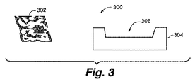
図3はある実施形態による鋳造システム300を概略的に表現する。システム300は概して、熱ブランケット302と、モールドキャビティ306を画定するモールド304とを含む。いくつかの実施形態によれば、物品を鋳造するための方法は、熱ブランケット302をモールドキャビティ306内に位置決めすることを含む。熱ブランケット300は、第1表面および第2表面を有する断熱材料層を含む。いくつかの場合、熱ブランケット302は、図1〜2Bに関連して上に記載した熱ブランケットの1つ、または上に記載されるような圧縮された断熱材料の1つまたは複数の副層を組み込む熱ブランケットであってもよい。モールド304は多数の異なる種類のモールドであることができ、異なるタイプの鋳造用に構成することができる。いくつかの場合、モールド304は、重力鋳造に有用であり得る。
FIG. 3 schematically represents a
図4はある実施形態による鋳造システム400を概略的に表現する。システム400は概して、第1熱ブランケット402および第2熱ブランケット404と、モールドキャビティ408を画定するモールド406とを含む。いくつかの実施形態によれば、物品を鋳造するための方法は、第1および第2熱ブランケット402、404をモールドキャビティ408内に位置決めすることを含む。熱ブランケット400はそれぞれ、第1表面および第2表面を有する断熱材料層を含む。いくつかの場合、熱ブランケット402、404は、図1〜2Bに関連して上に記載した熱ブランケットの1つ、または上に記載されるような圧縮された断熱材料の1つまたは複数の副層を組み込む熱ブランケットであってもよい。モールド406は多数の異なる種類のモールドであることができ、異なるタイプの鋳造用に構成することができる。いくつかの場合、モールド406は、第1モールド部分410および第2モールド部分412を含み、直接高圧鋳造法の間、それらを相互に押し付けることができる。
FIG. 4 schematically represents a
図5はある実施形態による鋳造システム500を概略的に表現する。システム500は概して、3つの熱ブランケット502、504および506と、モールドキャビティ510を画定するモールド508とを含む。さらに、システム500はプリフォームまたはインサート512を含む。いくつかの実施形態によれば、物品を鋳造するための方法は、熱ブランケット502、504および506を、プリフォームまたはインサート512と一緒にモールドキャビティ510内に位置決めすることを含む。熱ブランケットはそれぞれ、第1表面および第2表面を有する断熱材料層を含む。いくつかの場合、熱ブランケットは、図1〜2Bに関連して上に記載した熱ブランケットの1つ、または上に記載されるような圧縮された断熱材料の1つまたは複数の副層を組み込む熱ブランケットであってもよい。モールド508は多数の異なる種類のモールドであることができ、異なるタイプの鋳造用に構成することができる。いくつかの場合、モールド508は、第1モールド部分520、第2モールド部分522、射出スリーブ524、およびプランジャ526を含み、プランジャ526は、間接高圧鋳造法の間、溶融材料をモールドキャビティ510に射出するように作動させることができる。
FIG. 5 schematically represents a
図3〜5は本明細書に記載される実施形態による物品を鋳造するために使用できる可能なシステムの数例を示すが、それら図は単なる例であり、他の実施形態のシステムの他の構成を制限することを意味しないことは認識されよう。単なる一例として、いくつかのシステムは、モールド、複数の熱ブランケット、および複合物品を鋳造するために使用される複数のプリフォームおよび/またはインサートを含んでもよい。 Although FIGS. 3-5 illustrate several examples of possible systems that can be used to cast articles according to embodiments described herein, the figures are merely examples, and other systems of other embodiments It will be appreciated that it does not mean limiting the configuration. By way of example only, some systems may include a mold, a plurality of thermal blankets, and a plurality of preforms and / or inserts used to cast a composite article.
物品を鋳造するためのいくつかの方法は、上に記載されたもののうちの1つなどの1つまたは複数の熱ブランケットの使用を含んでもよい。いくつかの実施形態によれば、熱ブランケットは、間接高圧鋳造モールドの一部である射出スリーブおよび/または射出先端部の隔絶を補助するために使用することができる。周知のように、射出スリーブおよび射出先端部を介してモールドに射出される溶融材料はいくつかの場合、材料がモールドキャビティに到達する前でさえ、射出スリーブ/射出先端部内にある間、凝固または固化し始めることがある。いくつかの場合、早過ぎる凝固は、溶融材料が射出スリーブおよび/または先端部の内側表面に蓄積することを引き起こす恐れがあり、およびいくつかの場合、溶融材料をモールドキャビティに導入するための流路の部分的または完全な遮断をもたらし得る。いくつかの場合、この問題は特に小型の射出先端部に取り組むときに顕著である。いくつかの実施形態によれば、熱ブランケットを射出スリーブおよび/または射出先端部内に位置決めし、モールド機構のそれら部分を溶融材料から隔絶することができる。例えば、溶融材料が射出スリーブを介して先端部およびモールドキャビティに押し込まれるとき、溶融材料は熱ブランケットの横を通過し、かつ熱ブランケットと接触し得るが、いくつかの場合、顕著な範囲まで熱ブランケットを透過することも浸透することもなく、材料は自由に先端部を介してモールドキャビティに流れ続ける。さらに、いくつかの場合、熱ブランケットは、いくつかの場合に他の種類の断熱が困難であろうモールドのいくつかの部分を溶融材料から隔絶することができる。例えば、いくつかの熱ブランケットおよび/または熱ブランケット内の断熱層は、約0.0625インチ未満の合計厚みを有し得る。 Some methods for casting an article may include the use of one or more thermal blankets, such as one of those described above. According to some embodiments, the thermal blanket can be used to assist in the isolation of the injection sleeve and / or injection tip that is part of the indirect high pressure casting mold. As is well known, the molten material that is injected into the mold through the injection sleeve and injection tip in some cases solidifies or remains in the injection sleeve / injection tip, even before the material reaches the mold cavity. May start to solidify. In some cases, premature solidification can cause the molten material to accumulate on the inner surface of the injection sleeve and / or tip, and in some cases, the flow to introduce the molten material into the mold cavity. May result in partial or complete blockage of the road. In some cases, this problem is particularly noticeable when working with small injection tips. According to some embodiments, a thermal blanket can be positioned within the injection sleeve and / or injection tip to isolate those portions of the mold mechanism from the molten material. For example, when the molten material is pushed through the injection sleeve into the tip and mold cavity, the molten material can pass next to the thermal blanket and contact the thermal blanket, but in some cases the heat is to a significant extent. The material continues to flow freely through the tip and into the mold cavity without penetrating or penetrating the blanket. Further, in some cases, the thermal blanket can isolate some portions of the mold from the molten material that in some cases may be difficult to insulate other types of. For example, some thermal blankets and / or thermal insulation layers within the thermal blankets may have a total thickness of less than about 0.0625 inches.
いくつかの実施形態によれば、(熱ブランケット層を形成する)除去された副層は、約0.0001インチ〜約0.0625インチの厚みを有する。いくつかの場合、厚みは約0.03インチ〜約0.06インチであるように選択される。いくつかの実施形態によれば、除去された副層210(例えば熱ブランケット層)の厚みは約0.03インチである。従って、非常に薄い熱ブランケットを、それらの小さい厚みのため、狭いまたは収縮された領域内で使用することができる。 According to some embodiments, the removed sublayer (forming the thermal blanket layer) has a thickness of about 0.0001 inches to about 0.0625 inches. In some cases, the thickness is selected to be from about 0.03 inches to about 0.06 inches. According to some embodiments, the thickness of the removed sublayer 210 (eg, thermal blanket layer) is about 0.03 inches. Thus, very thin thermal blankets can be used in narrow or constricted areas due to their small thickness.
いくつかの実施形態によれば、物品を鋳造するための方法は、鋳物内部の固化の方向を制御するために少なくとも2つの熱ブランケットを使用することを含む。例えば、いくつかの場合、第1熱ブランケットをモールドキャビティ内にモールドキャビティ表面に対向して位置付けることができる。次に、ある量の溶融材料をモールドキャビティに導入することができる。溶融材料を導入した後、第2熱ブランケットを溶融材料の上面に位置付けることができる。いくつかの場合、第1および第2熱ブランケットの一方は他方より薄く、それにより固化の方向の制御がもたらされ得る。例えば、いくつかの場合、熱ブランケットの薄い方の層が、厚い方の層より早く摩耗し始め、分解し得る。いくつかの場合、熱ブランケットの薄い方の層はより劣る断熱その厚い方の層を提供し、従って熱は薄い方の層を通してより簡単に移行され、その結果、薄い方の層で固化の開始がもたらされる。固化は、厚い方の熱ブランケット層に到達するまで溶融材料を通って進むことができる。 According to some embodiments, a method for casting an article includes using at least two thermal blankets to control the direction of solidification within the casting. For example, in some cases, the first thermal blanket can be positioned in the mold cavity opposite the mold cavity surface. An amount of molten material can then be introduced into the mold cavity. After introducing the molten material, the second thermal blanket can be positioned on the top surface of the molten material. In some cases, one of the first and second thermal blankets is thinner than the other, which can provide control of the direction of solidification. For example, in some cases, the thinner layer of the thermal blanket begins to wear faster and can decompose than the thicker layer. In some cases, the thinner layer of the thermal blanket provides a poorer insulation that thicker layer, so heat is more easily transferred through the thinner layer, so that the thin layer begins to solidify Is brought about. Solidification can proceed through the molten material until it reaches the thicker thermal blanket layer.
いくつかの実施形態によれば、熱ブランケットを使用して鋳物内部に機能的勾配を生じさせることができる。周知のように、いくつかの種類の溶融材料は、1種または複数種の溶融金属を含み、いくつかの場合、金属と混合される粒子物質またはセラミック繊維物質を含み得る。いくつかの場合によれば、溶融材料が熱ブランケットに浸透し通過するとき、溶融材料内の特別な/繊維物質が熱ブランケットを通過することが難しい傾向にあるように、熱ブランケットをモールド内に位置付けることができる。従って、粒子および/または繊維の層または量が、熱ブランケットの界面に蓄積する傾向にある。粒子および/または繊維の分画量を含む溶融材料の一例はDuralcanであり、それはRio Tinto Alcanによって製造されている。例えば、1つの可能な使用において、Duralcan材料は、材料がモールドキャビティに導入されるとき、30体積含有率であり得、粒子物質が熱ブランケットを通過することが困難であるせいで、熱ブランケットの界面で最大約60体積含有率であり得る。いくつかの場合、その後溶融材料は、モールドキャビティの別側に近づくにつれ約30体積含有率まで低下するように調整し戻してもよく、従って溶融材料内に機能的勾配がもたらされる。言うまでもなくこれは可能な機能的勾配のほんの一例であり、本明細書中の出願人の開示に基づいて多数の変更を実行できることは認識されよう。 According to some embodiments, a thermal blanket can be used to create a functional gradient within the casting. As is well known, some types of molten material include one or more molten metals, and in some cases may include particulate or ceramic fiber materials that are mixed with the metal. According to some cases, when the molten material penetrates and passes through the thermal blanket, the thermal blanket is placed in the mold so that the special / fiber material in the molten material tends to be difficult to pass through the thermal blanket. Can be positioned. Thus, a layer or amount of particles and / or fibers tends to accumulate at the thermal blanket interface. An example of a molten material containing a fraction of particles and / or fibers is Duralcan, which is manufactured by Rio Tinto Alcan. For example, in one possible use, the Duralcan material can be 30 volume content when the material is introduced into the mold cavity, and because of the difficulty in passing particulate matter through the thermal blanket, There may be up to about 60 volume content at the interface. In some cases, the molten material may then be adjusted back down to about 30 volume content as it approaches the other side of the mold cavity, thus providing a functional gradient within the molten material. It will be appreciated that this is just one example of a possible functional gradient and that many changes can be made based on the applicant's disclosure herein.
いくつかの実施形態によれば、モールドキャビティ内の溶融材料が、導入後、どのように、どこにおよび/またはいつモールド表面と接触するかに関する制御措置を提供するために、1つまたは複数の熱ブランケットをモールドキャビティ内に位置付けることができる。他の箇所で考察されるように、金属などの溶融材料は、いくつかの場合、迅速な熱交換により、モールド壁と接触するとすぐに非常に迅速に固化することができる。いくつかの実施形態では、圧力が溶融材料に適用されるまで溶融材料がモールド壁と接触することを防止するために、1つまたは複数の熱ブランケットをモールドキャビティ内に位置付けることができる。例えば、溶融材料がモールドキャビティに導入されるとき、溶融材料はキャビティ全体に分散し、最終的に1つまたは複数の熱ブランケットの1つまたは複数の部分と接触し得る。材料の量が増加し続けるとき、材料はいくつかの場合、熱ブランケットと接触する表面張力面を形成し、従って材料が熱層を通過してモールドキャビティ壁に達することを防止し得る。言い換えると、モールドキャビティが満たされているとき、熱ブランケットは溶融材料をモールドキャビティ壁の1つまたは複数の部分から隔絶する。いくつかの場合、いったんキャビティが満たされると、追加の溶融材料がモールドに射出され、従って既にモールドキャビティを満たしている材料に圧力を適用し得る。いくつかの場合、キャビティを満たすことができ、そして、例えば複数のモールド部分を接合すること、上側モールドプレートを締め付けること等によってモールドを閉ざすことによって圧力を適用することができる。従って、いくつかの実施形態は、圧力が適用されるまでの溶融材料がモールド壁と接触する瞬間を制御(例えば延ばすまたは遅らせる)ことができる。いくつかの場合、いったん所望の圧力に到達すると、溶融材料は熱ブランケットとの界面で表面張力を突破し、熱ブランケットに浸透し始める。浸透が進むにつれ、溶融材料はより多くの熱量を周囲環境に奪われ、部分的な固化を開始し得る一方で移動する、従っていくつかの熱ブランケット中の繊維および/または粒子構造を分解する。 According to some embodiments, one or more heats are provided to provide control measures regarding how, where and / or when the molten material in the mold cavity contacts the mold surface after introduction. A blanket can be positioned in the mold cavity. As discussed elsewhere, molten materials such as metals can solidify very quickly as soon as they come into contact with the mold wall, due to rapid heat exchange. In some embodiments, one or more thermal blankets can be positioned within the mold cavity to prevent the molten material from contacting the mold wall until pressure is applied to the molten material. For example, when molten material is introduced into the mold cavity, the molten material can be dispersed throughout the cavity and eventually contact one or more portions of one or more thermal blankets. As the amount of material continues to increase, the material may in some cases form a surface tension surface that contacts the thermal blanket, thus preventing the material from passing through the thermal layer and reaching the mold cavity wall. In other words, when the mold cavity is filled, the thermal blanket isolates the molten material from one or more portions of the mold cavity wall. In some cases, once the cavity is filled, additional molten material can be injected into the mold, thus applying pressure to the material already filling the mold cavity. In some cases, the cavity can be filled and pressure can be applied by closing the mold, eg, by joining multiple mold parts, clamping the upper mold plate, and the like. Thus, some embodiments can control (eg, lengthen or delay) the moment the molten material contacts the mold wall until pressure is applied. In some cases, once the desired pressure is reached, the molten material breaks through the surface tension at the interface with the thermal blanket and begins to penetrate the thermal blanket. As infiltration progresses, the molten material is deprived of more heat by the surrounding environment and moves while it can begin partial solidification, thus breaking down the fiber and / or particle structure in some thermal blankets.
いくつかの場合、いったんモールドキャビティ内の所望の圧力に到達すると、溶融材料は瞬間的に見え得る様式で非常に素早くモールド表面と接触し得る。単なる一例として、いくつかの場合、所望の圧力に到達することにより溶融材料は約0.25インチ厚である熱ブランケットに浸入かつ浸透され、続いて約200ミリ秒で完全に固化される。従って、いくつかの場合、熱ブランケットは、例えばブランケットを圧迫する溶融材料の表面張力のせいで、溶融材料をモールドキャビティ壁などのモールド内の他の構造から隔絶または分離するのに有用であり得る。いくつかの場合、いったん圧力が適用されると、熱ブランケット内(例えばセラミック繊維材料内)の強化繊維は溶融材料から生じる増大する力に簡単に道を譲り渡し得る。溶融材料が浸透し、固化し始めるとき、固化する材料の移動は、いくつかのブランケット内のセラミック繊維材料を微細な片に分解する傾向にある。そのような片は肉眼で見えないかもしれないが、検出するために走査型電子顕微鏡を必要とし得る。 In some cases, once the desired pressure in the mold cavity is reached, the molten material can contact the mold surface very quickly in a manner that can be seen instantaneously. By way of example only, in some cases, reaching the desired pressure causes the molten material to penetrate and penetrate a thermal blanket that is about 0.25 inches thick, followed by complete solidification in about 200 milliseconds. Thus, in some cases, the thermal blanket can be useful to isolate or separate the molten material from other structures in the mold, such as the mold cavity wall, due to, for example, the surface tension of the molten material compressing the blanket. . In some cases, once pressure is applied, the reinforcing fibers in the thermal blanket (eg, in the ceramic fiber material) can easily give way to the increasing forces arising from the molten material. As the molten material penetrates and begins to solidify, the movement of the solidifying material tends to break the ceramic fiber material in some blankets into fine pieces. Such a piece may not be visible to the naked eye, but may require a scanning electron microscope to detect.
本明細書に記載される特定の実施形態は、モールドキャビティ内での1つまたは複数の熱ブランケットの位置決めを記載する。いくつかの場合、位置決めは、ブランケットをモールドに大まかに横たえるのと同程度に簡単であり得る。従って、ブランケットを使用して、注入する間溶融材料をモールドキャビティの側面から隔絶するための一種の保持池を作り出すことができ、その結果、固化する前に、必要な材料のほとんどすべてがモールドキャビティまで進む。十分な量の溶融材料が「保持池」に導入されると、圧力を適用して溶融材料を熱ブランケットを通過させ、キャビティの表面に到達させることができる。従って、熱ブランケットはいくつかの場合、溶融金属がほとんど瞬間的にモールドキャビティの表面のほとんどすべてまたはすべてに入って来ることを可能にするのに有用であり得る。モールドの全表面に沿った同時またはほとんど同時の凝固は、いくつかの場合、最終鋳物内のより望ましい固化パターズ(patters)を促進し得る。 Certain embodiments described herein describe the positioning of one or more thermal blankets within a mold cavity. In some cases, positioning can be as simple as roughly laying the blanket on the mold. Thus, a blanket can be used to create a kind of holding basin for isolating the molten material from the side of the mold cavity during pouring, so that almost all of the required material is removed from the mold cavity prior to solidification. Proceed to Once a sufficient amount of molten material has been introduced into the “retention pond”, pressure can be applied to allow the molten material to pass through the thermal blanket and reach the surface of the cavity. Thus, thermal blankets may be useful in some cases to allow molten metal to enter almost all or all of the mold cavity surface almost instantaneously. Simultaneous or near simultaneous solidification along the entire surface of the mold may in some cases promote more desirable solidification patterns within the final casting.
いくつかの場合、熱ブランケットは、モールドキャビティの主要な形状(例えば主な表面間の移行等)に全体的に従い得るが、いくつかの場合、表面のささいな形状に厳密に従わなくてよい。例えば、いくつかの場合、モールドは、鋳物の主要本体と一緒に鋳造されるとき表面特徴部を形成するいくつかのより小さい空隙、隙間、凹部、流路等を画定し得る。いくつかの場合、そのような表面特徴部の上に熱ブランケットを横たえることができるが、小さい凹部の中に挿入しなくてもよく、またモールド内のすべてのささいな細部に正確に従わなくてよい。いくつかの場合、モールドキャビティ表面のいくつかの部分は、「被覆されない」まま残してもよいと考えられる。なぜなら、一般に熱ブランケットの使用により、キャビティのほとんどまたはすべてを満たすことが可能になり得るからであり、続いて加圧すると、加圧前に熱ブランケットにより溶融材料はモールドの全表面の非常に近くまで来ることが許容されているので、全てのより小さい亀裂、隙間、流路、窪み等をほとんど瞬間的に満たすことができる。 In some cases, the thermal blanket may generally follow the major shape of the mold cavity (eg, transition between major surfaces, etc.), but in some cases may not strictly follow the minor shape of the surface. For example, in some cases, the mold may define a number of smaller voids, gaps, recesses, channels, etc. that form surface features when cast with the main body of the casting. In some cases, a thermal blanket can be laid over such surface features, but does not need to be inserted into a small recess and does not accurately follow all the minor details in the mold. Good. In some cases, it is contemplated that some portions of the mold cavity surface may remain “uncoated”. This is because, in general, the use of a thermal blanket may make it possible to fill most or all of the cavities, and when subsequently pressurized, the thermal blanket causes the molten material to be very close to the entire surface of the mold before pressing. All the smaller cracks, gaps, channels, depressions, etc. can be filled almost instantaneously.
いくつかの場合、例えば、モールドの全ての形状または特徴部を、熱ブランケットで正確に適合させる必要はない。例えば、いくつかの場合、溶融材料が加圧前に鋳物の所望の最終形状により近づくかできるだけ近づくように、モールドキャビティの形状に概ね適合することで十分であり得る。これにより溶融材料がより小さい特徴部の方に流れなければならない距離をより短くすることができ、およびモールドキャビティの部分が早期に固化することが防止され得る。いくつかの場合、従って特徴部を熱ブランケットで概ね覆うことにより、溶融材料が時期尚早に固化する可能性がより高いかもしれない「被覆されない」移動距離を低減または最小化することができる。いくつかの場合、熱ブランケットを使用して、モールドのより厚い部分に通じるランナまたは流路として使用されるモールドのより薄い部分を覆うことができる。従って、ブランケットにより、モールドのより厚い部分が満たされる前、より薄い部分を通る材料流が時期尚早に凝固および閉塞することが防止され得る。 In some cases, for example, not all shapes or features of the mold need be accurately matched with a thermal blanket. For example, in some cases, it may be sufficient to generally conform to the shape of the mold cavity so that the molten material is closer or as close as possible to the desired final shape of the casting prior to pressing. This can reduce the distance that the molten material must flow toward the smaller features and can prevent the mold cavity portion from solidifying prematurely. In some cases, thus, generally covering the features with a thermal blanket can reduce or minimize the “uncoated” travel distance where the molten material may be more likely to solidify prematurely. In some cases, a thermal blanket can be used to cover the thinner part of the mold that is used as a runner or flow path leading to the thicker part of the mold. Thus, the blanket may prevent premature solidification and plugging of the material flow through the thinner portion before the thicker portion of the mold is filled.
いくつかの場合、1つまたは複数の熱ブランケットの使用により、通常使用され得るよりも低温の温度で鋳造モールドを稼働させることができる鋳造プロセスが提供され得る。より低温のモールド温度により、今度はより速い固化時間を実現することができ、より速い固化時間により、溶融材料の改善された固化(例えば、より細かい粒子、わずかの長い粒子、より少ない樹枝状結晶成長(dendrite growths)等)がもたらされ得る。いくつかの場合、モールドキャビティを裏打ちするために1つまたは複数の熱ブランケットを使用する鋳造方法は、金属鋳造プロセスに一般的である250℃に近い温度とは対照的に室温(例えば約20℃)のモールドで実行され得る。従って、いくつかの実施形態は、250Cに近い温度で作動されるモールドに典型的な特性と実質的に同じである、室温のモールド内での材料流れ特性をもたらすことができ、同時により高い固化または冷却速度ももたらす。 In some cases, the use of one or more thermal blankets can provide a casting process that can operate the casting mold at a lower temperature than would normally be used. The lower mold temperature can in turn achieve a faster setting time, and the faster setting time improves the solidification of the molten material (eg finer particles, few longer particles, fewer dendrites) Growth, etc.) can be effected. In some cases, casting methods that use one or more thermal blankets to line the mold cavities are at room temperature (eg, about 20 ° C.) as opposed to temperatures close to 250 ° C. that are common in metal casting processes. ). Thus, some embodiments can provide material flow characteristics in a room temperature mold that are substantially the same as those typical for molds operated at temperatures close to 250 C, while at the same time higher solidification. Or it also provides a cooling rate.
いくつかの実施形態によれば、1つまたは複数の熱ブランケットの使用により溶融金属の滞留時間が延長され得る。ほんの一例として、いくつかの場合、熱ブランケットをモールドキャビティ内に位置決めすることにより、秒、ミリ秒、およびより短い単位のオーダーではなく分のオーダーの滞留時間がもたらされ得る。いくつかの実施形態によれば、鋳造プロセスの間熱ブランケットを使用することにより30秒以上の滞留時間がもたらされ得る。いくつかの場合、熱ブランケットにより約1分〜約10分の滞留時間がもたらされ得る。いくつかの場合、もたらされる滞留時間は約3〜8分であり得る。いくつかの場合、滞留時間は約4分または約5分以上であり得る。いくつかの場合、滞留時間を調整するために、熱ブランケットの厚みを(例えばより少ないまたはより多い断熱材料の副層を選択することによって)調整することができる。 According to some embodiments, the use of one or more thermal blankets can extend the residence time of the molten metal. By way of example only, in some cases, positioning a thermal blanket within a mold cavity can result in residence times on the order of minutes rather than on the order of seconds, milliseconds, and shorter units. According to some embodiments, the use of a thermal blanket during the casting process can provide a residence time of 30 seconds or more. In some cases, a thermal blanket can provide a residence time of about 1 minute to about 10 minutes. In some cases, the resulting residence time can be about 3-8 minutes. In some cases, the residence time can be about 4 minutes or about 5 minutes or more. In some cases, the thickness of the thermal blanket can be adjusted (eg, by selecting fewer or more sublayers of insulating material) to adjust the residence time.
いくつかの場合、増大された滞留時間により、複合材料の鋳造を含む様々な鋳造方法に利点を提供することができる。例えば、延長または増大された滞留時間により、鋳造プロセスの間、タイル、インサート、プリフォームおよび他の種類の物体をモールドキャビティ内に配置するのに有用である追加の時間がもたらされ得る。いくつかの過去の方法では、非常に速い固化速度のため、材料を複合的鋳物に挿入するのに多数の人員が必要とされる場合がある。対照的に、熱ブランケットを使用すると、必要な人員はより少なくなる場合があり、および/またはプリフォームの位置の正確性を向上するために滞留時間がもたらされる場合があり、パーフォームが所望の間隔で分配されること等が保証される。これは高性能材料を鋳造するのに有用であり得、また、増大された滞留時間の間、鋳物の特性を調整することによって鋳物の性能を選択的に変更することをより簡単にし得る。 In some cases, increased residence time can provide advantages for various casting methods including casting of composite materials. For example, an extended or increased residence time can provide additional time that is useful for placing tiles, inserts, preforms, and other types of objects in the mold cavity during the casting process. Some past methods may require a large number of personnel to insert the material into the composite casting due to the very fast solidification rate. In contrast, the use of a thermal blanket may require less personnel and / or may provide dwell time to improve the accuracy of the position of the preform so that the perform is desired. It is guaranteed that it is distributed at intervals. This can be useful for casting high performance materials and can make it easier to selectively change the performance of a casting by adjusting the properties of the casting during an increased residence time.
いくつかの場合、増大された滞留時間により、溶融材料の初期注入と、それに続くキャビティ内への1つまたは複数の物体の配置とが可能になり得、それらは材料によって封入されることを意味する。物体を申し分なく配置した後、いくつかの場合、圧力を適用して鋳造プロセスを終了し、および溶融材料をそのように全ての部分に押し込めることができ、それが熱ブランケットによって予め隔絶されたモールドキャビティ。従って、増大された滞留時間は、複合材料の鋳造に有用であり得ることは認識されよう。なぜなら、増大された滞留時間は、最終的な鋳物の特性を調整するために異なる物体(例えばインサート、異なる密度を有するセラミックプリフォーム層等)を配置できるより長い期間を提供するからである。 In some cases, the increased residence time may allow for the initial injection of molten material and subsequent placement of one or more objects in the cavity, meaning they are encapsulated by the material To do. After the object has been perfectly placed, in some cases, pressure can be applied to finish the casting process, and the molten material can be pushed into all parts so that it is pre-isolated by a thermal blanket cavity. Thus, it will be appreciated that increased residence time may be useful for casting composite materials. This is because the increased residence time provides a longer period in which different objects (eg, inserts, ceramic preform layers having different densities, etc.) can be placed to adjust the final casting properties.
いくつかの実施形態によれば、1つまたは複数の熱ブランケットの使用により、1つまたは複数のダイ壁の熱伝導率を効率的に修正する能力が提供され得る。ほんの一例として、いくつかの場合、熱ブランケットの少なくとも一部を、1つまたは複数のモールド壁に対してモールドキャビティ内に位置付けることができる。選択されたモールド壁に対して熱ブランケットを配置することによりモールド壁のその部分は断熱され、従ってモールド壁の熱伝導率プロファイルは変更される。そのような配置されたブランケットを有するモールド内に溶融材料が導入されるとき、溶融材料は、材料がむき出しのモールド壁と接触するか、熱ブランケットで断熱されたモールド壁の一部と接触するかに応じて、異なる熱変化を経験する。従って、溶融材料は部分的(例えばモールド壁のむき出しの部分と接触する部分)に他の部分(例えば熱ブランケットと接触する部分)より速く熱を失うので、モールドの1つまたは複数の壁、または壁を部分的に断熱することにより、鋳物中の方向性のある固化を促進することができる。従って、様々なサイズの熱ブランケットを使用して、モールドの異なる部分を選択的に断熱し、それにより鋳物の異なる部分を異なる時間および/または速度で固化することができ、それは鋳物物品の所望の材料特性を生じさせるのに有用であり得る。 According to some embodiments, the use of one or more thermal blankets may provide the ability to efficiently modify the thermal conductivity of one or more die walls. By way of example only, in some cases, at least a portion of the thermal blanket can be positioned within the mold cavity relative to one or more mold walls. By placing a thermal blanket against the selected mold wall, that portion of the mold wall is insulated, thus changing the thermal conductivity profile of the mold wall. When molten material is introduced into a mold having such an arranged blanket, does the molten material contact the exposed mold wall or a portion of the mold wall that is insulated with a thermal blanket? Depending on, you will experience different thermal changes. Thus, the molten material loses heat partially (eg, in contact with the exposed portion of the mold wall) faster than other portions (eg, in contact with the thermal blanket), so one or more walls of the mold, or By partially insulating the walls, directional solidification in the casting can be promoted. Thus, various sizes of thermal blankets can be used to selectively insulate different parts of the mold, thereby allowing different parts of the casting to solidify at different times and / or speeds, which may be desired for the cast article. It can be useful to produce material properties.
いくつかの実施形態によれば、第1熱ブランケットはキャビティを実質的に裏打ちするためにモールドキャビティ内に位置付けることができる。溶融材料をキャビティに注入した後、モールドを閉じて加圧する前に、追加の熱ブランケットを溶融材料の上に配置することができる。従って、溶融材料は実際には断熱性の囲みの内側にあり、断熱性の囲みにより時期尚早の固化の可能性は、どの一点においても、モールドキャビティの残り部分を満たした後でもっぱら密閉され加圧されるモールドの開放端部の近くでさえ、低減される。 According to some embodiments, the first thermal blanket can be positioned within the mold cavity to substantially line the cavity. After injecting the molten material into the cavity, an additional thermal blanket can be placed over the molten material before closing and pressurizing the mold. Therefore, the molten material is actually inside the insulating enclosure, and the possibility of premature solidification due to the insulating enclosure is only sealed and added after filling the rest of the mold cavity at any one point. Even near the open end of the mold to be pressed.
いくつかの実施形態によれば、熱ブランケットは、上に記載したような多くの異なる種類の鋳造方法で使用することができる。いくつかの場合、熱ブランケットは、いずれかの有用な場所に、および/またはいずれかのモールド表面、プリフォームまたはインサート表面と接触させて、あるいは異なる種類の溶融材料の間に、位置付けることができる。 According to some embodiments, the thermal blanket can be used in many different types of casting methods as described above. In some cases, the thermal blanket can be positioned at any useful location and / or in contact with any mold surface, preform or insert surface, or between different types of molten materials. .
本明細書で使用される際、用語プリフォームは、溶融材料で浸透させることができる材料を指すために使用される。また、用語インサートは本明細書中、浸透されないであろう材料片を示すために使用される。例えば、インサートは、鋼片のような固体材料であり得る。いくつかの実施形態によれば、プリフォームは、例えばプリフォームをタイルまたはインサートの下に配置することによって、熱隔離装置として使用することができる。いくつかの場合、プリフォームは、熱い(例えば加熱された)タイルと冷たいダイキャビティとの間の間隔を保持する特徴部を有することができる。 As used herein, the term preform is used to refer to a material that can be impregnated with a molten material. The term insert is also used herein to indicate a piece of material that will not penetrate. For example, the insert can be a solid material such as a billet. According to some embodiments, the preform can be used as a thermal isolation device, for example by placing the preform under a tile or insert. In some cases, the preform may have features that maintain a spacing between hot (eg, heated) tiles and cold die cavities.
いくつかの図に示されるように、同じおよび/または異なる溶融材料を含む多レベルの積層を、異なる材料間に熱ブランケットを位置付けることによって形成することができる。いくつかの実施形態によれば、モールドキャビティに導入されかつ熱ブランケットと接触する溶融材料は、物品を鋳造するための方法で使用されるいずれかの適切な材料であり得る。いくつかの場合、溶融材料は、(例えば元素、複合または合金形態の)少なくとも1種類の金属を含み得る。いくつかの場合、アルミニウム、マグネシウムおよび/または鋼を含む1種または複数種の金属を使用することができる。さらに、いくつかの場合、溶融材料は粒子材料も含み得る。そのような材料の一例はDuralcanであり、それはアルミニウムに懸濁されたSiC粒子を含む。 As shown in some of the figures, multiple levels of laminate comprising the same and / or different molten materials can be formed by positioning a thermal blanket between different materials. According to some embodiments, the molten material introduced into the mold cavity and in contact with the thermal blanket can be any suitable material used in a method for casting an article. In some cases, the molten material may include at least one metal (eg, in elemental, composite or alloy form). In some cases, one or more metals including aluminum, magnesium and / or steel can be used. Further, in some cases, the molten material may also include particulate material. An example of such a material is Duralcan, which contains SiC particles suspended in aluminum.
いくつかの実施形態によれば、モールドキャビティ内で熱の隔絶のために1つまたは複数の熱ブランケットを使用することは、1つまたは複数のインサートを溶融材料から隔絶することも含み得る。従って、固化される材料の性能を改善することができる一方、溶融材料とインサートの間の接触持続時間を制限する。従って、熱ブランケットによって隔絶されるインサートおよび/またはプリフォームは、通常直面するであろう高熱状態に曝される必要はない。これによりインサートが望ましくない条件によって劣化される例が低減され得る。例えば、いくつかの実施形態により、固化の前、高温モールド材料と、時折感受性の高いインサートとの間の短い接触時間量がもっぱら提供され得る。一例として、いくつかの場合、熱ブランケットを使用して、モールドキャビティに挿入されるマグネシウム、アルミニウムおよび/またはチタニウムから作製される加工または鋳物プレートを保護することができる。 According to some embodiments, using one or more thermal blankets for heat isolation within the mold cavity may also include isolating the one or more inserts from the molten material. Thus, the performance of the material to be solidified can be improved while limiting the contact duration between the molten material and the insert. Thus, inserts and / or preforms that are isolated by a thermal blanket need not be exposed to the high heat conditions that would normally be encountered. This can reduce instances where the insert is degraded by undesirable conditions. For example, some embodiments may provide a short amount of contact time between the hot mold material and the occasionally sensitive insert prior to solidification. As an example, in some cases, a thermal blanket can be used to protect a processed or cast plate made from magnesium, aluminum and / or titanium inserted into a mold cavity.
図6は、ある実施形態による物品を鋳造するための方法600を示す流れ図である。方法は概して、熱ブランケットを提供すること(602)、熱ブランケットの少なくとも一部をモールドのモールドキャビティ内に位置付けること(604)、および続いて、溶融材料がモールドキャビティを満たすまで溶融材料をモールドキャビティに、熱ブランケットの第1表面と接触するように導入すること(606)を含む。
FIG. 6 is a flow diagram illustrating a
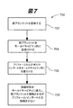
図7は、ある実施形態による物品を鋳造するための方法700を示す流れ図である。方法は概して、熱ブランケットを提供すること(702)、熱ブランケットの少なくとも一部をモールドのモールドキャビティ内に位置付けること(704)、1つまたは複数のプリフォームおよび/またはインサートをモールドキャビティ内に位置付けること(706)、および続いて、溶融材料がモールドキャビティを満たすまで溶融材料をモールドキャビティに、熱ブランケットの第1表面と接触するがプリフォームおよび/またはインサートと接触しないように導入すること(708)を含む。
FIG. 7 is a flow diagram illustrating a
図8は、ある実施形態による物品を鋳造するための方法800を示す流れ図である。方法は概して、第1熱ブランケットおよび第2熱ブランケットを提供すること(802)、第1熱ブランケットの少なくとも一部をモールドのモールドキャビティ内に位置付けること(804)、第1溶融材料をモールドキャビティに、第1熱ブランケットの第1表面と接触するように導入すること(806)を含む。方法はまた、第2熱ブランケットの少なくとも一部をモールドキャビティ内に位置付けること(808)、第2溶融材料をモールドキャビティに、第2熱ブランケットの第1表面と接触するように導入すること(810)を含む。
FIG. 8 is a flow diagram illustrating a
図9は、ある実施形態による物品を鋳造するための方法900を示す流れ図である。方法は概して、熱ブランケットを提供すること(902)、熱ブランケットの少なくとも一部をモールドのモールドキャビティ内に位置付けること(904)を含む。方法は次に、第1溶融材料をモールドキャビティに、熱ブランケットの第1表面と接触するように導入すること(906)を含む。方法はまた、少なくとも溶融材料が固化するまで圧力を適用すること(908)を含む。方法900の別のステップは、圧力を溶融材料に適用する(908)ときに熱ブランケットに溶融材料を浸透させること(910)を含む。
FIG. 9 is a flow diagram illustrating a
図10〜14は、ある実施形態による物品を鋳造するための方法における一連のステップを描いている。図10は、ある実施形態によるモールド1002と熱ブランケット1004とを含む鋳造システム1000を概略的に表現する。図11Aは、ある実施形態によるモールド1002のキャビティ1006内に位置付けられた熱ブランケット1004の斜視図である。例えば、この場合、熱ブランケット1004は、モールドキャビティ1006の内側表面を実質的に裏打ちするためにモールドキャビティのコーナーに押し込められ、ブランケット1004の余分な部分はモールドキャビティから単に伸びている。図11Bは図11Aの熱ブランケット1004とモールド1002の側面断面図である。
Figures 10-14 depict a series of steps in a method for casting an article according to an embodiment. FIG. 10 schematically represents a
図12はキャビティ1006への溶融材料1008の追加を示す。側面断面図から分かるように、熱ブランケット1004はモールド1002と溶融材料1008の間に位置付けられ、従ってモールド1002を溶融材料1008から熱的に隔絶している。図から分かるように、熱ブランケット1004は、実質的にモールドキャビティ1006全体が満たされるまで、溶融材料1008の初期部分をモールド1002から隔絶して保持する保持池を作り出す役割を果たす。
FIG. 12 shows the addition of
図13を見ると、いくつかの場合、追加の熱ブランケット1010を溶融材料1008の上に位置付けることができる。図13は、ある実施形態によるモールドキャビティ内および2つの熱ブランケット1004、1010の間に位置付けられた溶融材料1008の側面断面図である。
Turning to FIG. 13, in some cases, an additional
図14は、ある実施形態による固化後のモールド1002のモールドキャビティ1006内に位置する完成された鋳物1020の側面断面図である。例えば、モールド1002の上部(不図示)はいくつかの場合、底部1002に押し付けられてもよく、従って固化を開始するために圧力を溶融材料1008に適用する。図14に示されるように、いくつかの場合、圧力を適用して鋳造を終えることにより、鋳造プロセスで使用された熱ブランケット1004、1010の目立った存在なしに鋳物物品1020が製造される。上で考察したように、いくつかの場合、圧力を適用することは溶融材料1008をブランケット1004、1010に浸透させ、溶融材料1008にブランケットの分解を開始させ得る。
FIG. 14 is a side cross-sectional view of a finished casting 1020 located within a
図15は、2つの熱ブランケット1504、1506の間でモールドキャビティ1502内に位置付けられた第1溶融材料1500の側面断面図である。例はまた、第1溶融材料1500の上であるが2つの熱ブランケット1506、1520の間でモールドキャビティ1502内に位置付けられた第2溶融材料1508を示す。従って、この場合の3つの熱ブランケットの使用は、多レベル積層構造の形成を可能にすることができる。いくつかの場合、第1および第2溶融材料は同じものであってもよいが、いくつかの場合、それらは異なっていてもよい。認識されるように、モールドのサイズおよび層の厚みに応じて、いくつかの層を有する物品を鋳造するために、いくつかの熱ブランケットを一度に使用することができる。
FIG. 15 is a side cross-sectional view of a first
図16Aを見ると、多層高性能複合鋳物の例が、ある実施形態によるモールドに圧力を適用する前の鋳物1650の概略的な側面断面図で示されている。示されているように、いくつかの場合、熱ブランケット1606を、それぞれ異なる隣接層の間に位置付けることができるが、これは必須でなく、いくつかの場合、使用されなくてもよい。底壁および側壁と、直接高圧鋳造法実施形態において鋳物の加圧を可能にする移動式上壁とを含むモールド1900内の鋳物が示されている。複合物の性能を向上させるために、様々なインサート、プリフォームおよび他の材料を鋳物1650内に配置することができる。例えば、この場合、鋳物1650は、底部熱ブランケットの上に直接置かれた底部インサートまたはプレート1604を含む。次に熱ブランケットがプレート1604の上に位置付けられる。続いて複数のタイルおよび/またはインサート1608をこの熱ブランケットの上に位置付けることができ、そして別のプリフォーム1610をそのブランケットの上に位置付けることができる。最後に別のインサートまたはプレート1610が鋳物の上で2つのさらなる熱ブランケットの間に含まれる。
Turning to FIG. 16A, an example of a multilayer high performance composite casting is shown in a schematic side cross-sectional view of a
図16Aは、モールド1600が、キャビティ内の溶融材料に圧力を適用するように作動させることができる可動部分またはプランジャ1602を含むことを示す。この場合圧力を適用すると、上で考察されるように熱ブランケット1606は分解され、実質的に崩壊される。図16Bは、ある実施形態によるモールドに圧力を適用しかつ固化した後の図16Aの鋳物1670の概略的な側面断面図である。図から分かるように、熱ブランケット1606は実質的に消失している。
FIG. 16A shows that the
図17は、ある実施形態による鋳物1700の斜視的部分断面図である。鋳物の断面図は、鋳物1700の多数の層を示し、多数の層は、底部の低密度プリフォーム1702と、プリフォーム1702の上のカーボン繊維織物1704と、繊維織物1704の上のいくつかのセラミックタイル1706と、鋳物1700全体を囲み、封入し、それに浸透する金属合金層1708とを含む。図17には示されないが、いくつかの場合、鋳造の間、各層を隔絶するために、1つまたは複数の熱ブランケットを1つまたは複数の層の間に位置付けることができる(例えば参照番号1720を参照)。
FIG. 17 is a perspective partial cross-sectional view of a casting 1700 according to an embodiment. The cross-section of the casting shows multiple layers of the
図18はある実施形態による鋳物1800の側面断面図である。図から分かるように、鋳物1800は3種類の材料から形成される。見えないが、いくつかの場合、鋳造の間、各層を隔絶するために、第1熱ブランケットを位置1802に配置し、第2熱ブランケットを位置1804に配置することができる。
FIG. 18 is a side cross-sectional view of a casting 1800 according to an embodiment. As can be seen, the casting 1800 is formed from three types of materials. Although not visible, in some cases, a first thermal blanket can be placed at
いくつかの実施形態によれば、物品の鋳造方法は、熱ブランケットをモールドキャビティ内に配置することを含む。熱ブランケットはモールドキャビティの側面を裏打ちし、いくつかの場合、特定のプリフォームまたはインサートを裏打ちおよび/または封入する。溶融材料がモールドキャビティに導入されモールドが閉じられると、鋳物物品を形成するために、溶融材料の圧縮および固化の前、延長された滞留期間が実現される。 According to some embodiments, a method for casting an article includes placing a thermal blanket in a mold cavity. Thermal blankets line the side of the mold cavity and in some cases line and / or enclose certain preforms or inserts. When molten material is introduced into the mold cavity and the mold is closed, an extended dwell period is achieved before compression and solidification of the molten material to form a cast article.
いくつかの場合、プリフォームをモールドキャビティ内に位置付けることは、熱ブランケットがプリフォームのいくつかまたは全部をモールドキャビティの壁から隔絶することを保証し得る。 In some cases, positioning the preform within the mold cavity may ensure that the thermal blanket isolates some or all of the preform from the mold cavity walls.
いくつかの場合、熱ブランケットを位置付けることは、モールドキャビティ、およびいくつかの場合、分離したモールド実在物を溶融材料から実質的に隔絶する熱ブランケットを使用して、鋳物インサートおよびプリフォームを裏打ちすることを含む。 In some cases, positioning the thermal blanket lines the casting insert and preform using a mold cavity, and in some cases, a thermal blanket that substantially isolates the separated mold entity from the molten material. Including that.
いくつかの場合、プリフォームは多孔プリフォーム、可変密度プリフォームまたは多孔可変密度プリフォームであり、これらプリフォームは湿潤鋳造に適している。プリフォームは、例えばセラミック粒子、連続または非連続セラミック繊維、あるいはそれらの組合せを含み得る。さらに、プリフォームは、鋳物インサートの厳格な配置のための位置決め用熱隔絶装置として使用することもできる。 In some cases, the preform is a porous preform, a variable density preform or a porous variable density preform, which are suitable for wet casting. The preform can include, for example, ceramic particles, continuous or discontinuous ceramic fibers, or combinations thereof. Furthermore, the preform can also be used as a positioning thermal isolation device for strict placement of the casting insert.
いくつかの場合、熱ブランケットはセラミックベース繊維を含み、また熱ブランケットは熱処理され、約6#/Ft3から約12#/Ft3の範囲であり得る所望のかさ密度を達成するように圧縮される。 In some cases, the thermal blanket includes ceramic base fibers and the thermal blanket is heat treated and compressed to achieve a desired bulk density that can range from about 6 # / Ft 3 to about 12 # / Ft 3. The
いくつかの場合、熱ブランケットおよびプリフォームは、断面全体の材料構造を調整する役割を果たす。いくつかの場合、これを使用して、調整可能な材料特性を有する、材料厚み全体にわたる機能的勾配を生じさせることができる。 In some cases, thermal blankets and preforms serve to adjust the material structure across the cross section. In some cases this can be used to create a functional gradient across the material thickness with adjustable material properties.
いくつかの実施形態によれば、物品の鋳造方法は、プロセス中のステップを含み、ここで第1熱ブランケットがモールドキャビティ内に配置され、第1熱ブランケットはモールドキャビティの側面を裏打ちし、第1溶融材料がモールドキャビティの少なくとも一部に導入され、第2熱ブランケットが第1溶融材料の上に配置され、第2溶融材料が第2熱ブランケットの上に導入され、第2溶融材料は第1溶融材料と同じものであり、この多レベル積層は繰り返すことができ、モールドは閉じられ、そして鋳物物品を形成するために、溶融材料の加圧および固化の前、延長された滞留期間が実現される。 According to some embodiments, a method for casting an article includes an in-process step, wherein a first thermal blanket is disposed in a mold cavity, the first thermal blanket lines a side of the mold cavity, and a first A molten material is introduced into at least a portion of the mold cavity, a second thermal blanket is disposed over the first molten material, a second molten material is introduced over the second thermal blanket, and the second molten material is Same as 1 molten material, this multi-level lamination can be repeated, the mold is closed and an extended residence time is achieved before pressing and solidifying the molten material to form a cast article Is done.
いくつかの実施形態によれば、物品の鋳造方法は、プロセス中のステップを含み、ここで第1熱ブランケットがモールドキャビティ内に配置され、第1熱ブランケットはモールドキャビティの側面を裏打ちし、第1溶融材料がモールドキャビティの少なくとも一部に導入され、第2熱ブランケットが第1溶融材料の上に配置され、第2溶融材料が第2熱ブランケットの上に導入され、各溶融材料積層レベルは独自および特別のものであり、この多レベル積層は繰り返すことができ、モールドは閉じられ、そして鋳物物品を形成するために、溶融材料の加圧および固化の前、延長された滞留期間が実現される。 According to some embodiments, a method for casting an article includes an in-process step, wherein a first thermal blanket is disposed in a mold cavity, the first thermal blanket lines a side of the mold cavity, and a first One molten material is introduced into at least a portion of the mold cavity, a second thermal blanket is disposed over the first molten material, a second molten material is introduced over the second thermal blanket, and each molten material lamination level is Unique and special, this multi-level lamination can be repeated, the mold is closed, and an extended residence time is realized before pressing and solidification of the molten material to form a cast article The
このように本発明の実施形態は開示される。特定の開示された実施形態を参照してかなり詳細に例を記載したが、開示された実施形態は例示を目的として提示され、限定ではなく、本発明の他の実施形態が可能である。当業者であれば、本発明の趣旨および付随される請求項の範囲から逸脱することなく様々な変更、適合および修正を行うことができることを認識するであろう。 Thus, embodiments of the present invention are disclosed. Although examples have been described in considerable detail with reference to certain disclosed embodiments, the disclosed embodiments are presented for purposes of illustration and are not limiting, and other embodiments of the invention are possible. Those skilled in the art will recognize that various changes, adaptations and modifications can be made without departing from the spirit of the invention and the scope of the appended claims.
Claims (50)
断熱材料層を含み、かつ第1表面および第2表面を有する熱ブランケットを提供すること、
前記熱ブランケットの少なくとも一部をモールドキャビティ内に位置付けること、および、
溶融材料が前記モールドキャビティを満たすまで、前記溶融材料を前記モールドキャビティに導入し、前記熱ブランケットの前記第1表面と接触させることを含み、前記モールドキャビティ内の前記溶融材料が、前記モールドキャビティへの前記溶融材料の導入時から、少なくとも前記溶融材料が前記モールドキャビティを満たすまで延びる滞留時間の間、溶融状態を維持する、方法。 A method for casting an article comprising:
Providing a thermal blanket including a layer of thermal insulation material and having a first surface and a second surface;
Positioning at least a portion of the thermal blanket within a mold cavity; and
Introducing the molten material into the mold cavity until it is in contact with the first surface of the thermal blanket until the molten material fills the mold cavity, the molten material in the mold cavity entering the mold cavity Maintaining a molten state for a dwell time extending from the introduction of the molten material to at least the molten material filling the mold cavity.
断熱材料層を含みかつ第1表面および第2表面を有する熱ブランケットを提供すること、
前記熱ブランケットの少なくとも一部をモールドキャビティ内に位置付けること、
溶融材料を前記モールドキャビティに導入し、前記熱ブランケットの前記第1表面と接触させること、および、
前記溶融材料が固化するまで圧力を前記溶融材料に適用して鋳物物品の少なくとも一部を形成することを含み、
前記モールドキャビティ内の前記溶融材料が、前記モールドキャビティへの前記溶融材料の導入時から前記溶融材料への圧力の適用時まで延びる滞留時間の間、溶融状態を維持する、方法。 A method for casting an article comprising:
Providing a thermal blanket comprising a layer of thermal insulation material and having a first surface and a second surface;
Positioning at least a portion of the thermal blanket within a mold cavity;
Introducing a molten material into the mold cavity and contacting the first surface of the thermal blanket; and
Applying pressure to the molten material until the molten material solidifies to form at least a portion of a cast article;
The method wherein the molten material in the mold cavity remains in a molten state for a residence time extending from the time of introduction of the molten material into the mold cavity to the time of application of pressure to the molten material.
内側表面を含むモールドキャビティを画定するモールド、および、
断熱材料層を含む少なくとも1つの熱ブランケットを含み、前記少なくとも1つの熱ブランケットは、前記モールドキャビティに導入される溶融材料を、前記モールドキャビティの前記内側表面から隔絶するように構成され、その結果、少なくとも前記溶融材料が前記モールドキャビティを満たすまで、前記モールドキャビティ内の前記溶融材料が溶融状態を維持する、システム。 A system for casting an article,
A mold defining a mold cavity including an inner surface; and
Including at least one thermal blanket including a layer of thermal insulation material, wherein the at least one thermal blanket is configured to isolate molten material introduced into the mold cavity from the inner surface of the mold cavity; A system wherein the molten material in the mold cavity remains in a molten state at least until the molten material fills the mold cavity.
複数のセラミック繊維の副層を含むセラミック繊維材料を含む断熱材料層を提供すること、
前記断熱材料層を、約6lbs/ft3〜約12lbs/ft3の密度まで圧縮すること、
前記複数の副層のそれぞれの中の前記セラミック繊維を少なくとも部分的に一緒に焼結するように前記断熱材料層を加熱すること、および、
焼結後、前記複数のセラミック繊維の副層の1つまたは複数を除去することを含み、前記複数の副層の前記1つまたは複数が、物品を鋳造する際に使用する前記熱ブランケットを画定する、方法。 A method of making a thermal blanket for use in casting an article,
Providing a thermal insulation material layer comprising a ceramic fiber material comprising a plurality of ceramic fiber sublayers;
It said insulating material layer, be compressed to a density of about 6 lbs / ft 3 ~ about 12 lbs / ft 3,
Heating the thermal insulation material layer to at least partially sinter the ceramic fibers in each of the plurality of sublayers; and
Removing one or more of the plurality of ceramic fiber sublayers after sintering, wherein the one or more of the plurality of sublayers defines the thermal blanket for use in casting an article. how to.
Applications Claiming Priority (7)
| Application Number | Priority Date | Filing Date | Title |
|---|---|---|---|
| US201261623532P | 2012-04-12 | 2012-04-12 | |
| US61/623,532 | 2012-04-12 | ||
| US201261690727P | 2012-07-03 | 2012-07-03 | |
| US61/690,727 | 2012-07-03 | ||
| US13/840,423 | 2013-03-15 | ||
| US13/840,423 US9180511B2 (en) | 2012-04-12 | 2013-03-15 | Thermal isolation for casting articles |
| PCT/US2013/035890 WO2013155131A2 (en) | 2012-04-12 | 2013-04-10 | Thermal isolation for casting articles |
Publications (2)
| Publication Number | Publication Date |
|---|---|
| JP2015512788A true JP2015512788A (en) | 2015-04-30 |
| JP2015512788A5 JP2015512788A5 (en) | 2016-03-10 |
Family
ID=49324031
Family Applications (2)
| Application Number | Title | Priority Date | Filing Date |
|---|---|---|---|
| JP2015505863A Pending JP2015512789A (en) | 2012-04-12 | 2013-04-10 | Insulating spray for casting articles |
| JP2015505862A Pending JP2015512788A (en) | 2012-04-12 | 2013-04-10 | Insulation for casting articles |
Family Applications Before (1)
| Application Number | Title | Priority Date | Filing Date |
|---|---|---|---|
| JP2015505863A Pending JP2015512789A (en) | 2012-04-12 | 2013-04-10 | Insulating spray for casting articles |
Country Status (6)
| Country | Link |
|---|---|
| US (3) | US10434568B2 (en) |
| EP (2) | EP2836321A2 (en) |
| JP (2) | JP2015512789A (en) |
| CA (2) | CA2870311C (en) |
| HK (2) | HK1207031A1 (en) |
| WO (2) | WO2013155132A2 (en) |
Cited By (1)
| Publication number | Priority date | Publication date | Assignee | Title |
|---|---|---|---|---|
| US10179364B2 (en) | 2012-04-12 | 2019-01-15 | Rel, Inc. | Thermal isolation for casting articles |
Families Citing this family (4)
| Publication number | Priority date | Publication date | Assignee | Title |
|---|---|---|---|---|
| US9238390B2 (en) | 2012-07-03 | 2016-01-19 | Rel, Inc. | Composite articles, wear plates and methods |
| CA2919385C (en) | 2013-07-08 | 2017-03-14 | Rel, Inc. | Core structured components and containers |
| CN105479106B (en) * | 2015-12-18 | 2016-10-19 | 贵州航宇科技发展股份有限公司 | The forging forming method of 718Plus alloy |
| TWI727310B (en) * | 2019-04-19 | 2021-05-11 | 明創能源股份有限公司 | Temperature difference assembling component, assembling method and lightweight rigid body component with the component |
Citations (9)
| Publication number | Priority date | Publication date | Assignee | Title |
|---|---|---|---|---|
| JPS62202941U (en) * | 1986-06-13 | 1987-12-24 | ||
| JPS6336959A (en) * | 1986-07-31 | 1988-02-17 | Ube Ind Ltd | Casting method for high pressure casting |
| JPS63140751A (en) * | 1986-11-12 | 1988-06-13 | アルキャン・インターナショナル・リミテッド | Manufacture of composite casting article |
| JPH0357551A (en) * | 1989-07-21 | 1991-03-12 | Toyota Motor Corp | Internal chill method for ceramics body |
| JPH05177336A (en) * | 1991-12-27 | 1993-07-20 | Daishin Yoko:Kk | Method for composing steel member and aluminum casting |
| JPH1177240A (en) * | 1997-09-02 | 1999-03-23 | Matsushita Electric Ind Co Ltd | Casting metallic mold |
| JPH11267817A (en) * | 1998-03-23 | 1999-10-05 | Ngk Insulators Ltd | Press working |
| JP2003112242A (en) * | 2001-06-14 | 2003-04-15 | Fujitsu Ltd | Method for producing metallic formed body and metallic formed body produced with this method |
| JP2008188620A (en) * | 2007-02-02 | 2008-08-21 | Bridgestone Corp | Casting method and mold |
Family Cites Families (122)
| Publication number | Priority date | Publication date | Assignee | Title |
|---|---|---|---|---|
| US2426988A (en) | 1942-11-13 | 1947-09-09 | Aluminum Co Of America | Mold coating |
| US3230056A (en) | 1959-03-24 | 1966-01-18 | United States Steel Corp | Casting steel ingots |
| US3387646A (en) | 1963-09-18 | 1968-06-11 | Multifastener Corp | Method and apparatus for highpressure permanent molding |
| GB1031587A (en) | 1964-12-09 | 1966-06-02 | Rolls Royce | Ceramic shell mould |
| FR1478777A (en) * | 1965-05-14 | 1967-07-13 | ||
| US3472308A (en) | 1966-08-29 | 1969-10-14 | Multifastener Corp | Method and apparatus for permanent mold casting |
| GB1240301A (en) | 1968-10-03 | 1971-07-21 | Foseco Int | Production of metal castings |
| US3622404A (en) | 1969-02-19 | 1971-11-23 | Leonard E Thompson | Method and apparatus for stress relieving a workpiece by vibration |
| US3741820A (en) | 1970-12-07 | 1973-06-26 | A Hebel | Method for stress relieving metal |
| US3702279A (en) | 1971-04-07 | 1972-11-07 | Atomic Energy Commission | Fibrous thermal insulation and method for preparing same |
| US3736448A (en) | 1971-11-01 | 1973-05-29 | A Hebel | Displacement transducer |
| JPS5120295B2 (en) | 1972-04-11 | 1976-06-24 | ||
| JPS5236492B2 (en) | 1972-12-20 | 1977-09-16 | ||
| DE2431536A1 (en) | 1974-07-01 | 1976-01-22 | Metallgesellschaft Ag | Thermal insulating medium for cast iron mould walls - for use in casting accumulator grid plates of lead |
| US4136455A (en) | 1977-02-23 | 1979-01-30 | Century Specialties, Inc. | Floating head checking fixture |
| JPS54141209U (en) * | 1978-03-27 | 1979-10-01 | ||
| GB1595280A (en) | 1978-05-26 | 1981-08-12 | Hepworth & Grandage Ltd | Composite materials and methods for their production |
| US4264052A (en) | 1978-07-27 | 1981-04-28 | International Lead Zinc Research Organization, Inc. | Water-dispersible coatings containing boron nitride for steel casting dies |
| US4283847A (en) | 1979-05-24 | 1981-08-18 | Lear Siegler, Inc. | Circuit board assembly |
| JPS56500681A (en) | 1979-06-14 | 1981-05-21 | ||
| US4393100A (en) | 1979-12-26 | 1983-07-12 | General Electric Company | Method of coating a fused silica envelope |
| US4531973A (en) | 1980-04-08 | 1985-07-30 | Nixon Ivor G | Metallurgical processes |
| AU554140B2 (en) | 1980-07-02 | 1986-08-07 | Dana Corporation | Thermally insulating coating on piston head |
| CH650425A5 (en) * | 1981-05-21 | 1985-07-31 | Alusuisse | CHOCOLATE WITH HEAT-INSULATING PROTECTIVE LAYER. |
| US4416174A (en) | 1981-06-24 | 1983-11-22 | Century Specialties, Inc. | Auxiliary support fixture for a steady rest |
| JPS5815743A (en) | 1981-07-22 | 1983-01-29 | Izumi Jidosha Kogyo Kk | Piston and its manufacture for internal-combustion engine |
| US4404262A (en) | 1981-08-03 | 1983-09-13 | International Harvester Co. | Composite metallic and refractory article and method of manufacturing the article |
| GB2106433B (en) | 1981-09-22 | 1985-11-06 | Ae Plc | Squeeze casting of pistons |
| US4802425A (en) | 1982-12-16 | 1989-02-07 | The Babcock & Wilcox Company | High temperature fiber system with controlled shrinkage and stress resistance |
| GB8301320D0 (en) | 1983-01-18 | 1983-02-16 | Ae Plc | Reinforcement of articles of cast metal |
| DE3404121A1 (en) | 1984-02-07 | 1985-08-08 | M.A.N. Maschinenfabrik Augsburg-Nürnberg AG, 8900 Augsburg | HEAT-INSULATING PISTON FOR INTERNAL COMBUSTION ENGINES |
| US4546048A (en) | 1984-03-23 | 1985-10-08 | Dana Corporation | Composite thermal shield for engine components |
| GB8409044D0 (en) | 1984-04-07 | 1984-05-16 | Gkn Technology Ltd | Casting metal articles |
| GB8411074D0 (en) | 1984-05-01 | 1984-06-06 | Ae Plc | Reinforced pistons |
| US4770707A (en) | 1984-10-12 | 1988-09-13 | Manville Corporation | Method for forming a layer of refractory fibers on a surface and material produced thereby |
| JPS61201745A (en) | 1985-03-01 | 1986-09-06 | Toyota Motor Corp | Metallic composite material reinforced with alumina-silica fiber and mineral fiber |
| FR2592374B1 (en) | 1985-12-27 | 1991-08-16 | Peugeot | CERAMIC-METAL DIRECT LINKING PROCESS |
| US4665292A (en) | 1986-01-06 | 1987-05-12 | General Electric Company | Boil point prediction arrangement for cooking appliance |
| US4650775A (en) | 1986-04-29 | 1987-03-17 | The Babcock & Wilcox Company | Thermally bonded fibrous product |
| US4751205A (en) | 1986-04-29 | 1988-06-14 | The Babcock & Wilcox Company | Thermally bonded fibrous product |
| JPS63165562A (en) | 1986-12-27 | 1988-07-08 | 電気化学工業株式会社 | Heat resistant inorganic fiber molded body and its production |
| EP0280830A1 (en) | 1987-03-02 | 1988-09-07 | Battelle Memorial Institute | Method for producing metal or alloy casting, composites reinforced with fibrous or particulate materials |
| JPS63260655A (en) | 1987-04-15 | 1988-10-27 | Ube Ind Ltd | Sand core for pressure casting |
| JPS63268551A (en) | 1987-04-24 | 1988-11-07 | Suzuki Motor Co Ltd | Light alloy casting |
| DE3878495T2 (en) | 1987-06-18 | 1993-09-02 | Fibre Tech Ltd | METHOD FOR PROTECTING AND INSULATING A CATALYST BLOCK. |
| US4899800A (en) | 1987-10-15 | 1990-02-13 | Alcan International Limited | Metal matrix composite with coated reinforcing preform |
| DE3736280A1 (en) | 1987-10-27 | 1989-05-11 | Roehm Gmbh | METHOD FOR PRODUCING SCRATCH-PROOF COATED EXTRUDED PLASTIC LINES |
| JPH0688119B2 (en) * | 1988-05-25 | 1994-11-09 | 株式会社アーレスティ | Die casting |
| US5102745A (en) | 1989-11-13 | 1992-04-07 | Auburn University | Mixed fiber composite structures |
| US4968359A (en) | 1989-08-14 | 1990-11-06 | Bonal Technologies, Inc. | Stress relief of metals |
| IL95930A0 (en) | 1989-10-30 | 1991-07-18 | Lanxide Technology Co Ltd | Anti-ballistic materials and methods of making the same |
| US5394930A (en) | 1990-09-17 | 1995-03-07 | Kennerknecht; Steven | Casting method for metal matrix composite castings |
| FR2677641B1 (en) | 1991-06-17 | 1994-01-28 | Propulsion Ste Europeenne | PROCESS FOR THE PREPARATION OF PARTS OF COMPOSITE MATERIAL WITH AN ALUMINA MATRIX. |
| US5242512A (en) | 1992-03-13 | 1993-09-07 | Alloying Surfaces, Inc. | Method and apparatus for relieving residual stresses |
| DE4224078A1 (en) * | 1992-07-21 | 1994-01-27 | Hagen Batterie Ag | Lattice mold for casting accumulator lead grids and process for their production |
| US5252152A (en) | 1992-10-26 | 1993-10-12 | David J. Seror | Method of controlling warpage in workpiece by selective flame-hardening and vibrations |
| US5511603A (en) | 1993-03-26 | 1996-04-30 | Chesapeake Composites Corporation | Machinable metal-matrix composite and liquid metal infiltration process for making same |
| US5322109A (en) | 1993-05-10 | 1994-06-21 | Massachusetts Institute Of Technology, A Massachusetts Corp. | Method for pressure infiltration casting using a vent tube |
| US5451448A (en) | 1993-07-01 | 1995-09-19 | The United States Of America As Represented By The United States National Aeronautics And Space Administration | Flexible ceramic thermal protection system resistant to high aeroacoustic noise comprising a three-dimensional woven-fiber structure having a multilayer top fabric layer, a bottom fabric layer and an intermediate rib fabric layer |
| US5755272A (en) | 1993-12-02 | 1998-05-26 | Massachusetts Institute Of Technology | Method for producing metal matrix composites using electromagnetic body forces |
| US5373632A (en) | 1993-12-13 | 1994-12-20 | Mk Rail Corporation | Fabricating and machining procedures for crankcases for locomotive diesel engines |
| US5373630A (en) | 1993-12-13 | 1994-12-20 | Mk Rail Corporation | Cylinder conversion fabrication of crankcases for two-cycle V-type locomotive diesel engines |
| US5427853A (en) | 1993-12-20 | 1995-06-27 | General Motors Corporation | Reinforcement preform, method of making same and reinforced composite made therefrom |
| US5524696A (en) | 1994-08-05 | 1996-06-11 | General Motors Corporation | Method of making a casting having an embedded preform |
| US5588477A (en) | 1994-09-29 | 1996-12-31 | General Motors Corporation | Method of making metal matrix composite |
| US5679041A (en) | 1994-09-29 | 1997-10-21 | General Motors Corporation | Metal matrix composite and preform therefor |
| KR0153401B1 (en) | 1994-12-02 | 1998-11-16 | 전성원 | A manufacturing method of preformed body for complex material |
| ATE181867T1 (en) | 1996-02-06 | 1999-07-15 | Josef A Blach | DEVICE FOR CONTINUOUS PROCESSING OF FLOWING MATERIALS |
| US5980792A (en) | 1996-09-04 | 1999-11-09 | Chamlee; Thomas C. | Particulate field distributions in centrifugally cast composites |
| US5700409A (en) | 1996-11-13 | 1997-12-23 | Corry; Arthur A. | Method of molding an article |
| US6923942B1 (en) | 1997-05-09 | 2005-08-02 | 3M Innovative Properties Company | Compressible preform insulating liner |
| US6293680B1 (en) | 1997-09-10 | 2001-09-25 | Thermotrex Corporation | Electromagnetically controlled deformable mirror |
| DE19847104C1 (en) | 1998-10-13 | 1999-10-28 | 3 & Extruder Gmbh | High precision axial alignment of intermeshing screw shaft elements on a multi-shaft screw processing machine |
| DE19847102C1 (en) | 1998-10-13 | 2000-01-05 | 3 & Extruder Gmbh | Machine for continuously working flowing materials |
| DE19847103C1 (en) | 1998-10-13 | 1999-10-28 | 3 & Extruder Gmbh | Continuously working fluid material processing machine |
| AUPP939099A0 (en) | 1999-03-23 | 1999-04-15 | Cast Centre Pty Ltd | Die coatings for gravity and low pressure diecasting |
| DE19937798A1 (en) | 1999-08-10 | 2001-03-01 | Ks Aluminium Technologie Ag | Production of lightweight metal cast parts comprises coating the casting mold surface before each casting step with a thermal insulating layer |
| US6248286B1 (en) | 1999-12-03 | 2001-06-19 | Ut-Battelle, Llc | Method of making a functionally graded material |
| DE10009008C1 (en) | 2000-02-25 | 2001-09-13 | Bayern Freistaat | Process for producing a composite structure with a metal foam core |
| GB0004681D0 (en) | 2000-02-28 | 2000-04-19 | Saffil Limited | Method of making fibre-based products and their use |
| WO2002027048A2 (en) | 2000-09-28 | 2002-04-04 | 3M Innovative Properties Company | Ceramic oxide pre-forms, metal matrix composites, methods for making the same and disc brakes |
| US7048034B2 (en) | 2000-11-10 | 2006-05-23 | Buntrock Industries, Inc. | Investment casting mold and method of manufacture |
| DE10122462C1 (en) | 2001-05-09 | 2002-10-10 | 3 & Extruder Gmbh | Screw extruder has at least three parallel, intermeshing screws and casing with apertures in its side |
| JP3723522B2 (en) | 2001-08-03 | 2005-12-07 | 富士通株式会社 | Metal body manufacturing method |
| US20030056861A1 (en) | 2001-09-24 | 2003-03-27 | Weaver Samuel C. | Metal matrix composites of aluminum, magnesium and titanium using calcium hexaboride |
| DE10207145B4 (en) | 2002-02-20 | 2004-07-15 | Blach, Josef A. | Device for dispersing and melting flowable materials |
| US20050100724A1 (en) | 2002-05-02 | 2005-05-12 | Victrex Manufacturing Limited | Composite material |
| DE10233214B4 (en) | 2002-07-22 | 2005-01-27 | 3+Extruder Gmbh | Extruder for continuous processing and / or processing of flowable materials |
| DE10233213B4 (en) | 2002-07-22 | 2004-09-09 | 3+Extruder Gmbh | extruder |
| US7175722B2 (en) | 2002-08-16 | 2007-02-13 | Walker Donna M | Methods and apparatus for stress relief using multiple energy sources |
| US20040035547A1 (en) | 2002-08-20 | 2004-02-26 | 3M Innovative Properties Company | Metal matrix composites, and methods for making the same |
| US6994146B2 (en) * | 2002-11-12 | 2006-02-07 | Shaupoh Wang | Electromagnetic die casting |
| TWI280166B (en) | 2002-12-26 | 2007-05-01 | Toshiba Machine Co Ltd | Liquid material feed apparatus of die casting machine, liquid material feed method, and ladle |
| DE10315200B4 (en) | 2003-04-03 | 2005-03-17 | 3+Extruder Gmbh | Transmission for driving a multi-screw extruder |
| DE10317357B4 (en) | 2003-04-15 | 2006-10-26 | 3+Extruder Gmbh | extruder |
| ATE388153T1 (en) | 2003-07-11 | 2008-03-15 | Theravance Inc | CROSS-LINKED GLYCOPEPTIDE CEPHALOSPORIN ANTIBIOTICS |
| US7137675B1 (en) | 2003-09-19 | 2006-11-21 | Gs Engineering, Inc. | Road wheel for tracked vehicles |
| WO2005037458A2 (en) | 2003-10-14 | 2005-04-28 | Century Specialties | Sweep unit assembly |
| CA2554567A1 (en) | 2004-01-21 | 2005-08-04 | Benmaxx, Llc | Disc brake rotor assembly and method for producing same |
| US20050217950A1 (en) | 2004-03-11 | 2005-10-06 | Benmaxx, Llc | Lightweight reinforced brake drum and method for making same |
| JP4772388B2 (en) * | 2004-06-25 | 2011-09-14 | 株式会社クボタ | Plunger tip for die casting machine |
| US7055574B2 (en) | 2004-07-27 | 2006-06-06 | Honeywell International Inc. | Method of producing metal article having internal passage coated with a ceramic coating |
| DE102004051203B4 (en) | 2004-10-20 | 2013-06-20 | Blach Verwaltung Gmbh & Co.Kg | extruder |
| DE102004052055B4 (en) | 2004-10-26 | 2014-11-20 | Blach Verwaltung Gmbh & Co.Kg | extruder |
| US8765808B2 (en) | 2005-03-23 | 2014-07-01 | Chs Pharma, Inc. | Treatment or prevention of cancer and precancerous disorders |
| US20060283920A1 (en) | 2005-06-17 | 2006-12-21 | Siemens Westinghouse Power Corporation | Vibration stress relief of superalloy components |
| JP2007027967A (en) * | 2005-07-13 | 2007-02-01 | Fujifilm Holdings Corp | Photographing apparatus |
| JP4315933B2 (en) | 2005-07-21 | 2009-08-19 | 株式会社沖データ | Developer cartridge, developing device, and image forming apparatus |
| US7431193B2 (en) | 2005-08-19 | 2008-10-07 | Siemens Power Generation, Inc. | Vibration stress relief of weldments |
| EP1928573A4 (en) | 2005-08-30 | 2010-04-14 | Ind Ceramic Solutions Llc | Multiple integrated-layer ceramic fiber filter paper and method |
| US20070064222A1 (en) | 2005-09-20 | 2007-03-22 | Honeywell International Inc. | Systems and methods for testing and inspecting optical instruments |
| DE102005053907B4 (en) | 2005-11-11 | 2009-05-20 | Blach Verwaltung Gmbh & Co.Kg | Multi-screw extruder |
| US7481144B2 (en) | 2005-11-18 | 2009-01-27 | Gs Engineering, Inc. | Vibratory countermine system and method |
| US20070137827A1 (en) * | 2005-12-19 | 2007-06-21 | Howmet Corporation | Die casting in investment mold |
| US7323591B2 (en) | 2006-01-10 | 2008-01-29 | Allergan, Inc. | Substituted cyclopentanes or cyclopentanones as therapeutic agents |
| DE102006052610B4 (en) | 2006-11-08 | 2013-04-18 | Blach Verwaltungs Gmbh & Co. Kg | Multi-screw extruder |
| US8075827B2 (en) | 2006-12-01 | 2011-12-13 | Ftf, Llc | Variable-density preforms |
| JP4626645B2 (en) | 2007-11-27 | 2011-02-09 | ソニー株式会社 | Display device and optical device |
| US20090309252A1 (en) | 2008-06-17 | 2009-12-17 | Century, Inc. | Method of controlling evaporation of a fluid in an article |
| US7793703B2 (en) | 2008-06-17 | 2010-09-14 | Century Inc. | Method of manufacturing a metal matrix composite |
| WO2013099064A1 (en) | 2011-12-28 | 2013-07-04 | キヤノンアネルバ株式会社 | Vacuum treatment device |
| US10434568B2 (en) | 2012-04-12 | 2019-10-08 | Loukus Technologies, Inc. | Thermal isolation spray for casting articles |
-
2013
- 2013-03-15 US US13/836,001 patent/US10434568B2/en active Active
- 2013-03-15 US US13/840,423 patent/US9180511B2/en active Active
- 2013-04-10 EP EP13718691.2A patent/EP2836321A2/en not_active Withdrawn
- 2013-04-10 CA CA2870311A patent/CA2870311C/en active Active
- 2013-04-10 JP JP2015505863A patent/JP2015512789A/en active Pending
- 2013-04-10 WO PCT/US2013/035892 patent/WO2013155132A2/en active Application Filing
- 2013-04-10 JP JP2015505862A patent/JP2015512788A/en active Pending
- 2013-04-10 WO PCT/US2013/035890 patent/WO2013155131A2/en active Application Filing
- 2013-04-10 CA CA2870759A patent/CA2870759C/en active Active
- 2013-04-10 EP EP13718692.0A patent/EP2836320A2/en not_active Withdrawn
-
2015
- 2015-08-07 HK HK15107629.7A patent/HK1207031A1/en unknown
- 2015-08-07 HK HK15107628.8A patent/HK1207030A1/en unknown
- 2015-11-06 US US14/935,068 patent/US10179364B2/en active Active
Patent Citations (9)
| Publication number | Priority date | Publication date | Assignee | Title |
|---|---|---|---|---|
| JPS62202941U (en) * | 1986-06-13 | 1987-12-24 | ||
| JPS6336959A (en) * | 1986-07-31 | 1988-02-17 | Ube Ind Ltd | Casting method for high pressure casting |
| JPS63140751A (en) * | 1986-11-12 | 1988-06-13 | アルキャン・インターナショナル・リミテッド | Manufacture of composite casting article |
| JPH0357551A (en) * | 1989-07-21 | 1991-03-12 | Toyota Motor Corp | Internal chill method for ceramics body |
| JPH05177336A (en) * | 1991-12-27 | 1993-07-20 | Daishin Yoko:Kk | Method for composing steel member and aluminum casting |
| JPH1177240A (en) * | 1997-09-02 | 1999-03-23 | Matsushita Electric Ind Co Ltd | Casting metallic mold |
| JPH11267817A (en) * | 1998-03-23 | 1999-10-05 | Ngk Insulators Ltd | Press working |
| JP2003112242A (en) * | 2001-06-14 | 2003-04-15 | Fujitsu Ltd | Method for producing metallic formed body and metallic formed body produced with this method |
| JP2008188620A (en) * | 2007-02-02 | 2008-08-21 | Bridgestone Corp | Casting method and mold |
Cited By (1)
| Publication number | Priority date | Publication date | Assignee | Title |
|---|---|---|---|---|
| US10179364B2 (en) | 2012-04-12 | 2019-01-15 | Rel, Inc. | Thermal isolation for casting articles |
Also Published As
| Publication number | Publication date |
|---|---|
| US20160059305A1 (en) | 2016-03-03 |
| WO2013155132A2 (en) | 2013-10-17 |
| US20130269902A1 (en) | 2013-10-17 |
| HK1207031A1 (en) | 2016-01-22 |
| US20130269901A1 (en) | 2013-10-17 |
| US10179364B2 (en) | 2019-01-15 |
| CA2870311A1 (en) | 2013-10-17 |
| US9180511B2 (en) | 2015-11-10 |
| CA2870311C (en) | 2021-11-23 |
| CA2870759C (en) | 2017-10-31 |
| US10434568B2 (en) | 2019-10-08 |
| WO2013155131A3 (en) | 2014-01-16 |
| HK1207030A1 (en) | 2016-01-22 |
| EP2836321A2 (en) | 2015-02-18 |
| WO2013155131A2 (en) | 2013-10-17 |
| CA2870759A1 (en) | 2013-10-17 |
| JP2015512789A (en) | 2015-04-30 |
| EP2836320A2 (en) | 2015-02-18 |
| WO2013155132A3 (en) | 2014-01-16 |
Similar Documents
| Publication | Publication Date | Title |
|---|---|---|
| US10179364B2 (en) | Thermal isolation for casting articles | |
| JP3420572B2 (en) | Dies and methods for manufacturing parts | |
| Mizuuchi et al. | Processing of diamond particle dispersed aluminum matrix composites in continuous solid–liquid co-existent state by SPS and their thermal properties | |
| US6767619B2 (en) | Preform for manufacturing a material having a plurality of voids and method of making the same | |
| US5524696A (en) | Method of making a casting having an embedded preform | |
| US7063815B2 (en) | Production of composite materials by powder injection molding and infiltration | |
| JP2011523592A (en) | Method and apparatus for manufacturing a workpiece, in particular a forming tool or a forming tool part | |
| JP2004507367A (en) | Superplastic forming dies and mold inserts | |
| JP2015512788A5 (en) | ||
| JP2008284608A (en) | Casting method | |
| US7025109B1 (en) | Method and apparatus for controlling dispersion of molten metal in a mold cavity | |
| KR102352445B1 (en) | Die casting method and apparatus for metal alloy | |
| US7360577B2 (en) | Process for lost-foam casting with chill | |
| WO2003091464A3 (en) | Heating to control solidification of cast structure | |
| JPS63140751A (en) | Manufacture of composite casting article | |
| WO2006091619A2 (en) | Casting process | |
| JP2000042718A (en) | Casting method of cast product poured with material for composite | |
| JP2000288681A (en) | Production of cast material provided with ceramic-metal composite layer | |
| ITUD20100135A1 (en) | PROCEDURE FOR THE PRODUCTION OF AN ELEMENT SUBJECT TO WEAR, ITEM SUBJECT TO WEAR AND TEMPORARY AGGREGATION STRUCTURE FOR THE MANUFACTURE OF SUCH ITEM SUBJECT TO WEAR | |
| JPS58215263A (en) | Production of composite material | |
| EP3907018B1 (en) | Thermal management in lost wax casting | |
| AU2002305647B2 (en) | Preform for manufacturing a material having a plurality of voids and method of making same | |
| JP2012152771A (en) | Method for manufacturing metal-ceramic bonded substrate | |
| WO1990015681A1 (en) | Metal infiltration apparatus, methods and composites obtained thereby | |
| JPH03275268A (en) | Manufacture of fiber reinforced metal strip |
Legal Events
| Date | Code | Title | Description |
|---|---|---|---|
| A711 | Notification of change in applicant |
Free format text: JAPANESE INTERMEDIATE CODE: A711 Effective date: 20150902 |
|
| A521 | Request for written amendment filed |
Free format text: JAPANESE INTERMEDIATE CODE: A821 Effective date: 20150902 |
|
| A521 | Request for written amendment filed |
Free format text: JAPANESE INTERMEDIATE CODE: A523 Effective date: 20160121 |
|
| A621 | Written request for application examination |
Free format text: JAPANESE INTERMEDIATE CODE: A621 Effective date: 20160121 |
|
| A131 | Notification of reasons for refusal |
Free format text: JAPANESE INTERMEDIATE CODE: A131 Effective date: 20160930 |
|
| A601 | Written request for extension of time |
Free format text: JAPANESE INTERMEDIATE CODE: A601 Effective date: 20161221 |
|
| A601 | Written request for extension of time |
Free format text: JAPANESE INTERMEDIATE CODE: A601 Effective date: 20170227 |
|
| A521 | Request for written amendment filed |
Free format text: JAPANESE INTERMEDIATE CODE: A523 Effective date: 20170331 |
|
| A131 | Notification of reasons for refusal |
Free format text: JAPANESE INTERMEDIATE CODE: A131 Effective date: 20170511 |
|
| A601 | Written request for extension of time |
Free format text: JAPANESE INTERMEDIATE CODE: A601 Effective date: 20170728 |
|
| A02 | Decision of refusal |
Free format text: JAPANESE INTERMEDIATE CODE: A02 Effective date: 20180123 |