JP2015512489A - Mechanically controllable valve assembly, internal combustion engine and method of operating the internal combustion engine - Google Patents
Mechanically controllable valve assembly, internal combustion engine and method of operating the internal combustion engine Download PDFInfo
- Publication number
- JP2015512489A JP2015512489A JP2015503788A JP2015503788A JP2015512489A JP 2015512489 A JP2015512489 A JP 2015512489A JP 2015503788 A JP2015503788 A JP 2015503788A JP 2015503788 A JP2015503788 A JP 2015503788A JP 2015512489 A JP2015512489 A JP 2015512489A
- Authority
- JP
- Japan
- Prior art keywords
- valve
- gas inlet
- cylinders
- internal combustion
- combustion engine
- Prior art date
- Legal status (The legal status is an assumption and is not a legal conclusion. Google has not performed a legal analysis and makes no representation as to the accuracy of the status listed.)
- Pending
Links
Images


Classifications
-
- F—MECHANICAL ENGINEERING; LIGHTING; HEATING; WEAPONS; BLASTING
- F02—COMBUSTION ENGINES; HOT-GAS OR COMBUSTION-PRODUCT ENGINE PLANTS
- F02D—CONTROLLING COMBUSTION ENGINES
- F02D13/00—Controlling the engine output power by varying inlet or exhaust valve operating characteristics, e.g. timing
- F02D13/02—Controlling the engine output power by varying inlet or exhaust valve operating characteristics, e.g. timing during engine operation
- F02D13/06—Cutting-out cylinders
-
- F—MECHANICAL ENGINEERING; LIGHTING; HEATING; WEAPONS; BLASTING
- F01—MACHINES OR ENGINES IN GENERAL; ENGINE PLANTS IN GENERAL; STEAM ENGINES
- F01L—CYCLICALLY OPERATING VALVES FOR MACHINES OR ENGINES
- F01L1/00—Valve-gear or valve arrangements, e.g. lift-valve gear
- F01L1/34—Valve-gear or valve arrangements, e.g. lift-valve gear characterised by the provision of means for changing the timing of the valves without changing the duration of opening and without affecting the magnitude of the valve lift
-
- F—MECHANICAL ENGINEERING; LIGHTING; HEATING; WEAPONS; BLASTING
- F01—MACHINES OR ENGINES IN GENERAL; ENGINE PLANTS IN GENERAL; STEAM ENGINES
- F01L—CYCLICALLY OPERATING VALVES FOR MACHINES OR ENGINES
- F01L13/00—Modifications of valve-gear to facilitate reversing, braking, starting, changing compression ratio, or other specific operations
- F01L13/0005—Deactivating valves
-
- F—MECHANICAL ENGINEERING; LIGHTING; HEATING; WEAPONS; BLASTING
- F01—MACHINES OR ENGINES IN GENERAL; ENGINE PLANTS IN GENERAL; STEAM ENGINES
- F01L—CYCLICALLY OPERATING VALVES FOR MACHINES OR ENGINES
- F01L13/00—Modifications of valve-gear to facilitate reversing, braking, starting, changing compression ratio, or other specific operations
- F01L13/0015—Modifications of valve-gear to facilitate reversing, braking, starting, changing compression ratio, or other specific operations for optimising engine performances by modifying valve lift according to various working parameters, e.g. rotational speed, load, torque
- F01L13/0021—Modifications of valve-gear to facilitate reversing, braking, starting, changing compression ratio, or other specific operations for optimising engine performances by modifying valve lift according to various working parameters, e.g. rotational speed, load, torque by modification of rocker arm ratio
- F01L13/0026—Modifications of valve-gear to facilitate reversing, braking, starting, changing compression ratio, or other specific operations for optimising engine performances by modifying valve lift according to various working parameters, e.g. rotational speed, load, torque by modification of rocker arm ratio by means of an eccentric
-
- F—MECHANICAL ENGINEERING; LIGHTING; HEATING; WEAPONS; BLASTING
- F01—MACHINES OR ENGINES IN GENERAL; ENGINE PLANTS IN GENERAL; STEAM ENGINES
- F01L—CYCLICALLY OPERATING VALVES FOR MACHINES OR ENGINES
- F01L13/00—Modifications of valve-gear to facilitate reversing, braking, starting, changing compression ratio, or other specific operations
- F01L13/0015—Modifications of valve-gear to facilitate reversing, braking, starting, changing compression ratio, or other specific operations for optimising engine performances by modifying valve lift according to various working parameters, e.g. rotational speed, load, torque
- F01L13/0063—Modifications of valve-gear to facilitate reversing, braking, starting, changing compression ratio, or other specific operations for optimising engine performances by modifying valve lift according to various working parameters, e.g. rotational speed, load, torque by modification of cam contact point by displacing an intermediate lever or wedge-shaped intermediate element, e.g. Tourtelot
- F01L2013/0068—Modifications of valve-gear to facilitate reversing, braking, starting, changing compression ratio, or other specific operations for optimising engine performances by modifying valve lift according to various working parameters, e.g. rotational speed, load, torque by modification of cam contact point by displacing an intermediate lever or wedge-shaped intermediate element, e.g. Tourtelot with an oscillating cam acting on the valve of the "BMW-Valvetronic" type
-
- F—MECHANICAL ENGINEERING; LIGHTING; HEATING; WEAPONS; BLASTING
- F01—MACHINES OR ENGINES IN GENERAL; ENGINE PLANTS IN GENERAL; STEAM ENGINES
- F01L—CYCLICALLY OPERATING VALVES FOR MACHINES OR ENGINES
- F01L2305/00—Valve arrangements comprising rollers
-
- F—MECHANICAL ENGINEERING; LIGHTING; HEATING; WEAPONS; BLASTING
- F01—MACHINES OR ENGINES IN GENERAL; ENGINE PLANTS IN GENERAL; STEAM ENGINES
- F01L—CYCLICALLY OPERATING VALVES FOR MACHINES OR ENGINES
- F01L2800/00—Methods of operation using a variable valve timing mechanism
- F01L2800/08—Timing or lift different for valves of different cylinders
-
- Y—GENERAL TAGGING OF NEW TECHNOLOGICAL DEVELOPMENTS; GENERAL TAGGING OF CROSS-SECTIONAL TECHNOLOGIES SPANNING OVER SEVERAL SECTIONS OF THE IPC; TECHNICAL SUBJECTS COVERED BY FORMER USPC CROSS-REFERENCE ART COLLECTIONS [XRACs] AND DIGESTS
- Y02—TECHNOLOGIES OR APPLICATIONS FOR MITIGATION OR ADAPTATION AGAINST CLIMATE CHANGE
- Y02T—CLIMATE CHANGE MITIGATION TECHNOLOGIES RELATED TO TRANSPORTATION
- Y02T10/00—Road transport of goods or passengers
- Y02T10/10—Internal combustion engine [ICE] based vehicles
- Y02T10/12—Improving ICE efficiencies
Abstract
本発明は、それぞれ少なくとも1つのガス流入弁(8,10)と少なくとも1つのガス流出弁とを有する少なくとも2つのシリンダ(4,6)を備えた内燃機関用の、機械的に制御可能な動弁アセンブリであって、少なくとも各ガス流入弁(8,10)に、中間レバーアセンブリ(22,24)および旋回レバーアセンブリ(26,28)が対応して配置されているように、少なくとも1つの伝達アセンブリ(18,20)が設けられており、中間レバーアセンブリ(22,24)の中間レバー(30,32)は、旋回レバーアセンブリ(26,28)の旋回レバー(46,48)に作用結合する作業湾曲部(38,40)を有しており、中間レバー(30,32)は、カムシャフト(12)の周囲輪郭部(14,16)に作用結合しており、中間レバーアセンブリ(22,24)は、作用機構(64,66)を有しており、種々様々な弁リフト位置が調節可能であり、少なくとも1つの休止シリンダ(4)のガス流入弁(8)のゼロリフト位置が可能であるように、作用機構(64,66)が弁リフト調節装置(58)の制御輪郭部(60,62)に作用結合しており、弁リフト調節装置(58)は、制御シャフトを有しており、該制御シャフトに、制御輪郭部(60,62)が配置されており、全ての制御輪郭部(60,62)は、アイドリング範囲および全負荷範囲のためにはほぼ同一に形成されており、休止シリンダ(4)に設けられたガス流入弁(8)の、部分負荷範囲用の制御輪郭部(60)は、残りのシリンダ(6)に設けられたガス流入弁(10)の、部分負荷範囲用の制御輪郭部(62)に対して異なって形成された部分片(68)を有している。The invention relates to a mechanically controllable motion for an internal combustion engine comprising at least two cylinders (4, 6) each having at least one gas inlet valve (8, 10) and at least one gas outlet valve. A valve assembly, at least one transmission such that at least each gas inlet valve (8, 10) is correspondingly arranged with an intermediate lever assembly (22, 24) and a pivot lever assembly (26, 28). An assembly (18, 20) is provided and the intermediate lever (30, 32) of the intermediate lever assembly (22, 24) is operatively coupled to the pivot lever (46, 48) of the pivot lever assembly (26, 28). It has a working bend (38, 40) and the intermediate lever (30, 32) is operatively connected to the peripheral contour (14, 16) of the camshaft (12) The intermediate lever assembly (22, 24) has a working mechanism (64, 66) and is capable of adjusting a wide variety of valve lift positions, the gas inlet valve (8) of at least one idle cylinder (4). The action mechanism (64, 66) is operatively coupled to the control contour (60, 62) of the valve lift adjustment device (58) so that a zero lift position of the valve lift adjustment device (58) is possible. Having a control shaft on which the control contours (60, 62) are arranged, all the control contours (60, 62) being substantially free for idling and full load ranges The control contour part (60) for the partial load range of the gas inflow valve (8) provided in the rest cylinder (4) is identical to the gas inflow valve provided in the remaining cylinders (6). (10) Partial load range It has control contour (62) with respect to different portions formed pieces of use (68).
Description
本発明は、それぞれ少なくとも1のガス流入弁と、少なくとも1つのガス流出弁とを有する少なくとも2つのシリンダを備えた内燃機関用の、機械的に制御可能な動弁アセンブリであって、少なくとも各ガス流入弁に中間レバーアセンブリおよび旋回レバーアセンブリが対応して配置されているように、少なくとも1つの伝達アセンブリが設けられており、中間レバーアセンブリの中間レバーが、旋回レバーアセンブリの旋回レバーに作用結合する作業湾曲部を有しており、中間レバーは、カムシャフトの周囲輪郭部に作用結合しており、中間レバーアセンブリは作用機構を有しており、種々様々な弁リフト位置が調節可能であり、少なくとも1つの休止シリンダのガス流入弁のゼロリフト調節が可能であるように、作用機構が弁リフト調節装置の制御輪郭部に作用結合している、機械的に制御可能な動弁アセンブリに関する。 The present invention relates to a mechanically controllable valve assembly for an internal combustion engine comprising at least two cylinders each having at least one gas inlet valve and at least one gas outlet valve, wherein at least each gas At least one transmission assembly is provided such that the intermediate lever assembly and the swivel lever assembly are correspondingly disposed on the inflow valve, and the intermediate lever of the intermediate lever assembly is operatively coupled to the swivel lever of the swivel lever assembly. Has a working bend, the intermediate lever is operatively coupled to the peripheral contour of the camshaft, the intermediate lever assembly has a working mechanism, and various valve lift positions are adjustable; The actuating mechanism is valve lift adjustable so that zero lift adjustment of the gas inlet valve of at least one idle cylinder is possible. It is operatively connected to the control contour of the location, to mechanically controllable valve train assembly.
さらに本発明は、機械的に制御可能なこのような動弁アセンブリを備えた内燃機関およびそのような内燃機関を運転する方法に関する。 The invention further relates to an internal combustion engine comprising such a valve assembly that is mechanically controllable and a method of operating such an internal combustion engine.
このような動弁アセンブリは、十分に知られている。動弁アセンブリは特に、弁リフト高さによって、ひいては内燃機関のシリンダの充填度によって、燃焼プロセスを負荷要求にその都度適合させて、負荷要求に対してできるだけ効率のよい燃焼、ひいては有害物質の少ない燃焼をも生ぜしめるために使用される。さらに、特定の負荷範囲、特に部分負荷範囲では、幾つかの個数のシリンダを完全に休止させ、これによりたとえば、4気筒の内燃機関において、内燃機関を2つのシリンダのみで運転することができる。ここでも、燃焼プロセスの効率およびエミッション最適化が注目されている。シリンダ休止に関して、数多くの技術が知られている。この技術には、たとえば切換え可能なタイミングタペット、ロストモーション機能を有するスイングアーム式のロッカアームもしくは旋回レバーアセンブリ(Schwenkarmanordnung)ならびにゼロリフト輪郭を有するディスクカムが含まれる。これらの技術的なコンセプトにおいて問題となるのは、対応する弁が閉じられている場合、つまり2つの動作サイクル間で、休止されるべきシリンダの対応する弁の作動もしくは非作動化を実施しなければならないことである。これにより、内燃機関に対して緩衝すべき明らかな負荷飛躍が生じる。これにより、理論的な効率および利点は部分的に失われてしまう。 Such valve assemblies are well known. The valve assembly, in particular, adapts the combustion process to the load requirements each time, depending on the valve lift height and thus the degree of filling of the cylinder of the internal combustion engine. Used to cause combustion. Furthermore, in certain load ranges, in particular partial load ranges, several cylinders are completely deactivated, so that, for example, in a four-cylinder internal combustion engine, the internal combustion engine can be operated with only two cylinders. Again, attention is focused on combustion process efficiency and emission optimization. Numerous techniques are known for cylinder deactivation. This technique includes, for example, a switchable timing tappet, a swing arm rocker arm with a lost motion function or a swivel lever assembly (Schwenkarmanordnung) and a disc cam with a zero lift profile. The problem with these technical concepts is that if the corresponding valve is closed, that is, between two operating cycles, the corresponding valve of the cylinder to be deactivated must be activated or deactivated. It must be done. This creates a clear load jump that should be buffered against the internal combustion engine. This partially loses theoretical efficiency and benefits.
これに対して、独国特許出願公開第102006033559号明細書は、互いに独立して駆動可能な2つの弁リフト調節装置を有する、機械的に制御可能な動弁装置を記載している。該特許明細書によれば、弁リフト調節装置は、シリンダ休止のためにも利用され得る。互いに独立して運転されるべき弁リフト調節装置を設けることは、高められた組付け手間および費用の原因となる。 In contrast, German Offenlegungsschrift DE 102006033559 describes a mechanically controllable valve actuation device having two valve lift adjustment devices that can be driven independently of each other. According to the patent specification, the valve lift adjustment device can also be used for cylinder deactivation. Providing valve lift adjustment devices to be operated independently of each other causes increased assembly effort and cost.
したがって、本発明の課題は、上記の欠点を回避する、機械的に制御可能な動弁装置および内燃機関および該内燃機関を運転する方法を提供することにある。 Accordingly, it is an object of the present invention to provide a mechanically controllable valve gear, an internal combustion engine and a method for operating the internal combustion engine that avoid the above-mentioned drawbacks.
この課題を解決した本発明による機械的に制御可能な動弁装置の構成によれば、弁リフト調節装置が制御シャフトを有しており、該制御シャフトに制御輪郭部が配置されており、全ての制御輪郭部が、アイドリング範囲および全負荷範囲のためにはほぼ同一に形成されており、休止シリンダのガス流入弁の部分負荷範囲のための制御輪郭部は、残りのシリンダのガス流入弁の部分負荷範囲のための制御輪郭部に対して異なって形成された部分片を有している。これによって、たとえば列設されたシリンダにおいて、シリンダ休止を単に1つの調節装置によって実施することが可能である。 According to the configuration of the mechanically controllable valve operating apparatus according to the present invention that solves this problem, the valve lift adjusting device has a control shaft, and the control contour is arranged on the control shaft. The control contours for the idle cylinder and the full load range are substantially identical, and the control contours for the partial load ranges of the idle cylinder gas inlet valves are those of the remaining cylinder gas inlet valves. It has part pieces that are formed differently with respect to the control contour for the part load range. This makes it possible to carry out the cylinder deactivation with only one adjusting device, for example in a lined cylinder.
この場合、制御輪郭部が制御シャフトの基本円内に配置されていると、簡単で廉価な組立てのために特に有利である。 In this case, it is particularly advantageous for a simple and inexpensive assembly if the control contour is arranged in the basic circle of the control shaft.
この場合、休止シリンダに対応配置された制御輪郭部の部分片が、残りのシリンダに対応配置された制御輪郭部の対応する部分片に対してセットバックして配置されていると特に有利である。 In this case, it is particularly advantageous if the piece of the control contour arranged corresponding to the rest cylinder is set back with respect to the corresponding piece of the control contour arranged corresponding to the remaining cylinders. .
2つの中間レバーが、1つの結合シャフトを介して、作業湾曲部とは反対の側に位置する端部において互いに結合されており、カムシャフトの力伝達用に第1のローラが設けられており、中間レバーの間で滑子案内部内でのガイドのために第2のローラが設けられていることによって、特にコンパクトな機械的に制御可能な動弁アセンブリが達成される。 The two intermediate levers are connected to each other at the end located on the side opposite to the work bending portion via one connecting shaft, and a first roller is provided for transmitting the camshaft force. By providing a second roller for guiding in the slider guide between the intermediate levers, a particularly compact mechanically controllable valve assembly is achieved.
問題となる、効率を損なう負荷飛躍なしに使用される、内燃機関の、負荷に依存するシリンダ休止を保障するために、それぞれの制御輪郭部の半径rとガス流入弁のリフト高さhとは正比例しており、この場合、1つのシリンダのガス流入弁のリフト高さhは、当該シリンダ内の平均圧力pに対応していると、特に有利である。 In order to guarantee a load-dependent cylinder deactivation of an internal combustion engine, which is used without a problem and a load jump that impairs efficiency, the radius r of each control contour and the lift height h of the gas inlet valve are In this case, it is particularly advantageous if the lift height h of the gas inlet valve of one cylinder corresponds to the average pressure p in the cylinder.
上記課題は、機械的に制御可能な上記のような動弁アセンブリを備えた内燃機関によっても解決される。この場合、第1の制御輪郭部の半径r1は、第2の制御輪郭部の半径r2に関連して選択されており、内燃機関の部分負荷範囲では、内燃機関のシリンダ全体に関する圧力pgesが制御シャフト58の調節角度にわたって単調に上昇するように変化する。この場合、特に有利には、部分負荷範囲では、シリンダのうちの半数のシリンダは休止されている。
The above problem is also solved by an internal combustion engine provided with a valve assembly as described above that can be mechanically controlled. In this case, the radius r1 of the first control contour is selected in relation to the radius r2 of the second control contour, and in the partial load range of the internal combustion engine, the pressure p ges for the entire cylinder of the internal combustion engine is It changes so as to increase monotonically over the adjustment angle of the
本発明の課題は、内燃機関を運転する方法によって解決される。該方法では、トルクが上昇する方向で見て、アイドリング範囲では、全てのシリンダの少なくとも全てのガス流入弁を同一の、増大していくリフト高さで運転し、アイドリング範囲と部分負荷範囲との間の移行範囲では、シリンダのうちの半数のシリンダのガス流入弁を増大していくリフト高さで運転し、シリンダのうちの別の半数のシリンダのガス流入弁を減少していくリフト高さで運転し、部分負荷範囲では、シリンダのうちの半数のシリンダのガス流入弁を増大していくリフト高さで運転し、シリンダのうちの別の半数のシリンダのガス流入弁をゼロリフトで運転し、部分負荷範囲と全負荷範囲との間の移行範囲では、シリンダのうちの半数のシリンダのガス流入弁を減少していくリフト高さで運転し、シリンダのうちの別の半数のシリンダのガス流入弁を増大していくリフト高さで運転し、全負荷範囲では、全てのシリンダの全てのガス流入弁を同一の、増大していくリフト高さで運転する。 The object of the present invention is solved by a method of operating an internal combustion engine. In this method, when viewed in the direction of increasing torque, in the idling range, at least all gas inflow valves of all cylinders are operated at the same increasing lift height, and the idling range and the partial load range are In the transition range, the lift height that increases the gas inlet valve of half of the cylinders and increases the gas inlet valve of the other cylinder and decreases the gas inlet valve of the other half of the cylinders. In the partial load range, the gas inlet valve of half of the cylinders is operated at a lift height that increases, and the gas inlet valve of another half of the cylinders is operated at zero lift. In the transition range between the partial load range and the full load range, the gas inlet valve of half of the cylinders is operated at a lift height that decreases, and another half of the cylinders Operated lift height gradually increasing the Sunda gas inlet valve, in the full load range, the same for all the gas inlet valve of all cylinders are operated lift height gradually increases.
本発明を以下に図面につき詳しく説明する。 The invention is explained in more detail below with reference to the drawings.
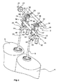
図1は、機械的に制御可能な動弁アセンブリ2の概略図を示している。この場合、ガス流入弁およびガス流出弁を有する2つのシリンダ4,6が示されている。見易くするために、ここではそれぞれ1つのガス流入弁8,10しか示されていない。
FIG. 1 shows a schematic view of a mechanically
さらに、カム14,16を備えたカムシャフト12が示されている。本実施の形態では、ガス流入弁8,10の弁リフトを引き起こすために、カム14,16がそれぞれ1つの伝達アセンブリ18,20に作用するように結合されている。見易くするために、動弁アセンブリの特定の部分、たとえば支承部、滑子案内部(Kulisse)およびばねは意図的に省略されている。これらの構成部材は、独国特許出願公開第102004003327号明細書に明瞭に記載されており、したがって上掲の特許明細書は、本明細書の開示内容に含まれるものとする。より良好に理解するために、図3から図7に関して、カム14,16は同一に配向されているが、このカムの配向は実際の場合には互いに異なっていて良い。
Furthermore, a
本実施の形態では、伝動アセンブリ18,20はそれぞれ、中間レバーアセンブリ22,24と旋回レバーアセンブリ26,28とから成っている。中間レバーアセンブリ22,24は、第1のローラ34,36を備えた中間レバー30,32を有している。第1のローラ34,36は、それぞれカムシャフト12のカム14,16に作用結合している。示唆されているように、1つの結合シャフト31が、シリンダ6の対応するガス流入弁10に対応して配置されている2つの中間レバー32を互いに結合している。結合シャフト31には、滑子案内部(図示せず)内におけるガイドのためのローラ33が設けられている。第1のローラ34,36とは反対の側に位置する端部で、各中間レバー30,32は、作業湾曲部38,40を有している。これらの作業湾曲部38,40は、さらに旋回レバーアセンブリ26,28のローラ42,44にそれぞれ作用結合している。この場合、ローラ42,44は、それぞれ旋回レバー46,48に支持されている。旋回レバー46,48は、さらに一方の側で支持位置50,52に支持されており、他方の側54,56でもって、公知の形式でガス流入弁8,10に作用する。ガス流入弁8,10の種々様々な弁リフト位置を調節するために、1つの弁リフト調節装置が設けられている。弁リフト調節装置のうち、図面には制御シャフト58しか示されていない。制御シャフト58は、このためには制御輪郭部60,62を介して中間レバー30,32の第2のローラ64,66に作用結合している。この図面では、制御輪郭部60が、特定の部分片を介して制御輪郭部62とは異なって実施されていることが示唆されている。
In the present embodiment, the transmission assemblies 18 and 20 include
別の図面により詳細に図示され説明されるように、制御シャフト58の回動は、ガス流入弁8,10の互いに異なる最大リフトをもたらす。作業輪郭60,62が、制御シャフト58の基本円内に位置していることによって、制御シャフトの特に簡単な支持が可能である。これに関しては、独国特許出願公開第102004003327号明細書が参照される。この場合、制御シャフト58は、一部分から形成されていても、複数の部分から形成されていてもよいことが示唆されている。さらに、制御シャフト58は、作動装置(図示せず)の較正を簡単にするために、端部ストッパを有していてよい。
As shown and described in more detail in another drawing, the pivoting of the
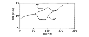
本実施の形態では、各制御輪郭部60,62の半径rと、各ガス流入弁8,10のリフト高さhとが正比例していることを前提とする。さらに各ガス流入弁8,10のリフト高さhは、さらに各シリンダ4,6内の平均圧力pに対応している。この場合、制御輪郭部62に対してセットバックされた部分片68を有する制御輪郭部60の流入弁8に対応して配置されたシリンダ4は、休止シリンダとして実施されていてよい。休止シリンダを休止または作動させるための移行範囲において不都合な負荷の飛躍が発生することを阻止するためには、内燃機関、つまりシリンダ全体の平均圧力pgesが制御シャフト58の正の調節角度にわたって、もしくは増大する負荷にわたって実質的に単調に上昇するように変化することを必要とする。この前提に基づいて、まず図2aの図を導くことができる。図2aでは、各制御輪郭部60,62の半径rが、制御シャフト58の調節角度に関連して記入されている。図2aに基づいて、次いで図2bに示すように、制御輪郭部60,62を、直接に導き出すことができる。連続生産における制御シャフト58の実施は、当然ながらこの数学的な導出から逸脱してよい。
In the present embodiment, it is assumed that the radius r of each
図3から図7は、動弁アセンブリ2を、各ガス流入弁8、10のリフト高さおよび位置で概略的に示し、添付のグラフに示す。この場合、上側のグラフは、各弁8,10のリフト高さをそれぞれ制御シャフト58の角度位置にわたって示し、下側のグラフは、それぞれのシリンダ4,6の平均圧力と、平均総圧力pgesの変化を制御シャフト58の調節角度にわたって示している。
3 to 7 schematically show the
図3は、出発位置として、アイドリング範囲の内燃機関の状態を示している。必要となる総圧pgesは、極めて小さく、この場合、約2barの範囲である。このことは、休止シリンダのガス流入弁を含む全てのガス流入弁の、約0.75mmリフト高さに一致する。線70,72で示されている流出弁は両方とも、動作タイミングに従って開放する。制御シャフト58の位置が明確に判る。この場合、第1の作業輪郭部60の作用点の半径r1は、第2の制御カム62の作用点の半径r2と同一である。負荷要求が上昇するにつれて、つまりアイドリング範囲と部分負荷範囲との間の移行範囲において、第1のシリンダ4のリフト−平均圧力は降下し、第2のシリンダ6のリフト−平均圧力は上昇する。このことは、図4に示されている。両流出弁は、いまだ作業タイミングに従って開放する。ここでも、制御輪郭部60が、制御輪郭部62に対してセットバックされた部分領域68で中間レバーアセンブリ22に作用していることが明らかである。
FIG. 3 shows the state of the internal combustion engine in the idling range as a starting position. The required total pressure p ges is very small, in this case in the range of about 2 bar. This corresponds to a lift height of about 0.75 mm for all gas inlet valves, including the idler cylinder gas inlet valve. Both outflow valves shown by
図5には、負荷要求がさらに上昇した場合に、第1のシリンダ4の流入弁8が閉じられたままであることが示されている。第1のシリンダ4に対応配置された流出弁も、線70にしたがって閉じられたままである。第2のシリンダ群6は、この場合、効率のよい高い負荷で運転され、この場合、シリンダ4,6全体で見てほぼ線形に上昇する圧力pgesが実現されるようになる。
FIG. 5 shows that the
図6は、部分負荷範囲と全負荷範囲との間の移行範囲の状態を示している。さらなる負荷要求は、この場合、第1のシリンダ群8を再作動することにより満たされ得る。エンジントルクの引き続き単調な変化を実現するために、第2のシリンダ10の負荷は対応して減じられる。
FIG. 6 shows the state of the transition range between the partial load range and the full load range. Further load requirements can be met in this case by reactivating the
図7は、全負荷範囲の状態を示している。両制御輪郭部60,62は、中間レバー30,32の各作用機構64,66に同じ半径で作用している。
FIG. 7 shows a state in the full load range. Both
Claims (9)
前記中間レバーアセンブリ(22,24)の中間レバー(30,32)は、前記旋回レバーアセンブリ(26,28)の旋回レバー(46,48)に作用結合する作業湾曲部(38,40)を有しており、
前記中間レバー(30,32)は、カムシャフト(12)の周囲輪郭部(14,16)に作用結合しており、
前記中間レバーアセンブリ(22,24)は、作用機構(64,66)を有しており、種々様々な弁リフト位置が調節可能であり、少なくとも1つの休止シリンダ(4)の前記ガス流入弁(8)のゼロリフト位置が可能であるように、前記作用機構(64,66)が弁リフト調節装置(58)の制御輪郭部(60,62)に作用結合している、機械的に制御可能な動弁アセンブリにおいて、
前記弁リフト調節装置(58)は、制御シャフトを有しており、該制御シャフトに、前記制御輪郭部(60,62)が配置されており、全ての制御輪郭部(60,62)は、アイドリング範囲および全負荷範囲のためにはほぼ同一に形成されており、
前記休止シリンダ(4)に設けられた前記ガス流入弁(8)の、部分負荷範囲用の前記制御輪郭部(60)は、残りのシリンダ(6)に設けられた前記ガス流入弁(10)の、部分負荷範囲用の前記制御輪郭部(62)に対して異なって形成された部分片(68)を有していることを特徴とする、機械的に制御可能な動弁アセンブリ。 A mechanically controllable valve assembly for an internal combustion engine comprising at least two cylinders (4, 6) each having at least one gas inlet valve (8, 10) and at least one gas outlet valve. And at least one transmission assembly (18, 10) such that at least each gas inlet valve (8, 10) is correspondingly disposed with an intermediate lever assembly (22, 24) and a pivot lever assembly (26, 28). 20)
The intermediate lever (30, 32) of the intermediate lever assembly (22, 24) has a work bending portion (38, 40) that is operatively coupled to the pivot lever (46, 48) of the pivot lever assembly (26, 28). And
The intermediate lever (30, 32) is operatively coupled to the peripheral contour (14, 16) of the camshaft (12);
The intermediate lever assembly (22, 24) has a working mechanism (64, 66), various valve lift positions are adjustable, and the gas inlet valve (4) of at least one idle cylinder (4). 8) a mechanically controllable mechanism in which the operating mechanism (64, 66) is operatively connected to the control contour (60, 62) of the valve lift adjustment device (58) so that the zero lift position of 8) is possible. In the valve assembly,
The valve lift adjusting device (58) has a control shaft on which the control contour (60, 62) is arranged, and all the control contours (60, 62) It is almost identical for the idling range and full load range,
The control contour (60) for the partial load range of the gas inlet valve (8) provided in the idle cylinder (4) is the gas inlet valve (10) provided in the remaining cylinder (6). A mechanically controllable valve assembly comprising a piece (68) formed differently with respect to the control contour (62) for a partial load range.
トルクが上昇する方向で見て、アイドリング範囲では、全てのシリンダ(4,6)の少なくとも全てのガス流入弁(8,10)を同一の、増大していくリフト高さで運転し、アイドリング範囲と部分負荷範囲との間の移行範囲では、前記シリンダのうちの半数のシリンダ(6)の前記ガス流入弁(10)を増大していくリフト高さで運転し、前記シリンダのうちの別の半数のシリンダ(4)の前記ガス流入弁(8)を減少していくリフト高さで運転し、部分負荷範囲では、前記シリンダのうちの半数のシリンダ(6)の前記ガス流入弁(10)を増大していくリフト高さで運転し、前記シリンダのうちの別の半数のシリンダ(4)の前記ガス流入弁(8)を、ゼロリフトで運転し、部分負荷範囲と全負荷範囲との間の移行範囲では、前記シリンダのうちの半数のシリンダ(6)の前記ガス流入弁(10)を減少していくリフト高さで運転し、前記シリンダのうちの別の半数のシリンダ(4)の前記ガス流入弁(8)を増大していくリフト高さで運転し、全負荷範囲では、前記全てのシリンダ(4,6)の全てのガス流入弁(8,10)を同一の、増大していくリフト高さで運転する、ことを特徴とする、内燃機関を運転する方法。 A method for operating an internal combustion engine according to claim 7 or 8,
When viewed in the direction of increasing torque, in the idling range, at least all the gas inflow valves (8, 10) of all the cylinders (4, 6) are operated at the same increasing lift height, and the idling range In the transition range between the cylinder and the partial load range, the gas inlet valve (10) of half of the cylinders (6) is operated at an increasing lift height, The gas inlet valves (8) of half of the cylinders (4) are operated at decreasing lift heights, and in the partial load range, the gas inlet valves (10) of half of the cylinders (6) are operated. And the gas inflow valve (8) of another half of the cylinders (4) is operated with zero lift, between the partial load range and the full load range. In the transition range of The gas inflow valve (10) of half of the cylinders (6) is operated at a decreasing lift height, and the gas inflow valve (8) of another half of the cylinders (4) is operated. ) With increasing lift height, and in the full load range, all the gas inlet valves (8, 10) of all the cylinders (4, 6) with the same increasing lift height. A method of operating an internal combustion engine, characterized in that it is operated.
Applications Claiming Priority (3)
| Application Number | Priority Date | Filing Date | Title |
|---|---|---|---|
| DE102012006983A DE102012006983A1 (en) | 2012-04-05 | 2012-04-05 | Mechanically controllable valve train arrangement, internal combustion engine and a method for operating an internal combustion engine |
| DE102012006983.9 | 2012-04-05 | ||
| PCT/EP2013/050839 WO2013149737A1 (en) | 2012-04-05 | 2013-01-17 | Mechanically controllable valve train assembly, internal combustion engine and method for operating an internal combustion engine |
Publications (2)
| Publication Number | Publication Date |
|---|---|
| JP2015512489A true JP2015512489A (en) | 2015-04-27 |
| JP2015512489A5 JP2015512489A5 (en) | 2016-07-28 |
Family
ID=47559521
Family Applications (1)
| Application Number | Title | Priority Date | Filing Date |
|---|---|---|---|
| JP2015503788A Pending JP2015512489A (en) | 2012-04-05 | 2013-01-17 | Mechanically controllable valve assembly, internal combustion engine and method of operating the internal combustion engine |
Country Status (6)
| Country | Link |
|---|---|
| US (1) | US9157381B2 (en) |
| EP (1) | EP2834483B1 (en) |
| JP (1) | JP2015512489A (en) |
| CN (1) | CN104271902B (en) |
| DE (1) | DE102012006983A1 (en) |
| WO (1) | WO2013149737A1 (en) |
Families Citing this family (7)
| Publication number | Priority date | Publication date | Assignee | Title |
|---|---|---|---|---|
| DE102014217531A1 (en) * | 2014-09-03 | 2016-03-17 | Ford Global Technologies, Llc | Valve lift control device with cylinder deactivation |
| DE102015111056A1 (en) | 2015-07-08 | 2017-01-12 | Volkswagen Aktiengesellschaft | Method for the efficiency-optimized switching of a four-stroke internal combustion engine with multiple cylinders and fully variable valve train between a full-cylinder operation and partial-cylinder operation |
| CN107035448A (en) * | 2015-07-31 | 2017-08-11 | 长城汽车股份有限公司 | For the valve actuating mechanism of engine and the vehicle with it |
| DE102015219875A1 (en) * | 2015-10-14 | 2017-04-20 | Bayerische Motoren Werke Aktiengesellschaft | Control shaft for intake valve deactivation |
| CN109312645B (en) * | 2016-04-21 | 2021-09-03 | 伊顿智能动力有限公司 | Valve train assembly |
| CN206889048U (en) * | 2017-06-09 | 2018-01-16 | 长城汽车股份有限公司 | Valve actuating mechanism, engine and vehicle |
| GB201710961D0 (en) * | 2017-07-07 | 2017-08-23 | Eaton Srl | Rocker arm |
Citations (4)
| Publication number | Priority date | Publication date | Assignee | Title |
|---|---|---|---|---|
| JP2006521495A (en) * | 2003-03-29 | 2006-09-21 | ヒュドラオリク−リング・ゲーエムベーハー | Variable valve lift device for lift adjustment of gas exchange valve of internal combustion engine |
| EP1760278A2 (en) * | 2005-08-30 | 2007-03-07 | Bayerische Motoren Werke Aktiengesellschaft | Lift-variable valve-operating system for internal combustion engine |
| JP2009030584A (en) * | 2007-07-04 | 2009-02-12 | Hitachi Ltd | Control apparatus for internal combustion engine |
| JP2011127433A (en) * | 2009-12-15 | 2011-06-30 | Suzuki Motor Corp | Variable valve train of internal combustion engine |
Family Cites Families (8)
| Publication number | Priority date | Publication date | Assignee | Title |
|---|---|---|---|---|
| DE10148347A1 (en) | 2001-09-29 | 2003-04-10 | Bosch Gmbh Robert | Torque-neutral cylinder deactivation by deactivating gas exchange valves |
| DE102004003327A1 (en) | 2004-01-22 | 2005-09-29 | Entec Consulting Gmbh | Variable valve lift device for internal combustion engine, has rotatable eccentric shaft having eccentrics contours positioned within circle formed by external diameter of bearings of eccentric shaft |
| DE10323665B4 (en) * | 2003-05-14 | 2009-02-05 | Hydraulik-Ring Gmbh | Variable valve lifting device for stroke adjustment of the gas exchange valves of an internal combustion engine |
| US7458346B2 (en) * | 2006-04-05 | 2008-12-02 | Ford Global Technologies, Llc | Method for controlling valves of an engine having a variable event valvetrain during an engine stop |
| DE102006033559A1 (en) | 2006-07-20 | 2008-01-24 | Bayerische Motoren Werke Ag | Valve drive unit for an internal combustion engine comprises a first adjusting unit assigned to a gas exchange valve of a first cylinder and a second adjusting unit assigned to the gas exchange valve of a second cylinder |
| DE102006055800A1 (en) | 2006-11-27 | 2008-05-29 | Robert Bosch Gmbh | Hybrid drive with valve shutdown |
| US8001936B2 (en) * | 2007-07-04 | 2011-08-23 | Hitachi, Ltd. | Control apparatus for internal combustion engine and control method therefor |
| DE102010062319B4 (en) * | 2010-12-02 | 2023-04-20 | Bayerische Motoren Werke Aktiengesellschaft | Cylinder deactivation in an internal combustion engine with variable valve lift |
-
2012
- 2012-04-05 DE DE102012006983A patent/DE102012006983A1/en not_active Withdrawn
-
2013
- 2013-01-17 US US14/390,028 patent/US9157381B2/en active Active
- 2013-01-17 WO PCT/EP2013/050839 patent/WO2013149737A1/en active Application Filing
- 2013-01-17 CN CN201380019682.4A patent/CN104271902B/en not_active Expired - Fee Related
- 2013-01-17 JP JP2015503788A patent/JP2015512489A/en active Pending
- 2013-01-17 EP EP13700334.9A patent/EP2834483B1/en active Active
Patent Citations (4)
| Publication number | Priority date | Publication date | Assignee | Title |
|---|---|---|---|---|
| JP2006521495A (en) * | 2003-03-29 | 2006-09-21 | ヒュドラオリク−リング・ゲーエムベーハー | Variable valve lift device for lift adjustment of gas exchange valve of internal combustion engine |
| EP1760278A2 (en) * | 2005-08-30 | 2007-03-07 | Bayerische Motoren Werke Aktiengesellschaft | Lift-variable valve-operating system for internal combustion engine |
| JP2009030584A (en) * | 2007-07-04 | 2009-02-12 | Hitachi Ltd | Control apparatus for internal combustion engine |
| JP2011127433A (en) * | 2009-12-15 | 2011-06-30 | Suzuki Motor Corp | Variable valve train of internal combustion engine |
Also Published As
| Publication number | Publication date |
|---|---|
| EP2834483A1 (en) | 2015-02-11 |
| CN104271902B (en) | 2016-11-09 |
| WO2013149737A1 (en) | 2013-10-10 |
| CN104271902A (en) | 2015-01-07 |
| EP2834483B1 (en) | 2019-03-13 |
| DE102012006983A1 (en) | 2013-10-10 |
| US20150047586A1 (en) | 2015-02-19 |
| US9157381B2 (en) | 2015-10-13 |
| WO2013149737A9 (en) | 2014-10-16 |
Similar Documents
| Publication | Publication Date | Title |
|---|---|---|
| JP2015512489A (en) | Mechanically controllable valve assembly, internal combustion engine and method of operating the internal combustion engine | |
| US7469669B2 (en) | Variable valve train mechanism of internal combustion engine | |
| ATE333571T1 (en) | VALVE DRIVE DEVICE FOR VARIABLE STROKE ADJUSTMENT OF A GAS EXCHANGE VALVE OF AN INTERNAL COMBUSTION ENGINE | |
| CN103437850B (en) | Continuously variable valve lift mechanism | |
| CN102155273A (en) | Variable gas distribution mechanism of engine | |
| JP2007523289A (en) | Exhaust valve mechanism for internal combustion engine | |
| EP1851419B1 (en) | Device for combustion engine | |
| JP2005282573A (en) | Adjustable lifting device | |
| JP2009287550A (en) | Continuously-variable valve lift device of engine | |
| JP2015512489A5 (en) | ||
| EP1515009A1 (en) | Engine valve driver | |
| JP4417260B2 (en) | Valve lift device for variable valve control of gas exchange valve of internal combustion engine | |
| US20130220251A1 (en) | Mechanically controllable valve drive | |
| US7424873B2 (en) | Variable valve mechanism | |
| US7665434B2 (en) | Internal combustion engine with continuous variable valve lift system | |
| US20140096729A1 (en) | Valve train and method for control time variation | |
| EP1387048A3 (en) | Rocking lever for valve drive with variable lift | |
| KR101317140B1 (en) | Continuous variable valve lift apparatus | |
| CN102966391B (en) | Swinging arm mechanism controlled by using double cams | |
| EP2157292A1 (en) | Valve gear assembly for an internal combustion engine | |
| KR100897263B1 (en) | Continuous variable valve lift apparatus | |
| US9464540B2 (en) | Transfer assembly for a mechanically controllable valve train | |
| US4495902A (en) | Mechanism for variably controlling an internal combustion engine valve | |
| CN103089362A (en) | Continuously variable valve lift system with default mechanism | |
| CN102678215A (en) | Simplifying mechanism of fully variable valve timing gear |
Legal Events
| Date | Code | Title | Description |
|---|---|---|---|
| A131 | Notification of reasons for refusal |
Free format text: JAPANESE INTERMEDIATE CODE: A131 Effective date: 20160201 |
|
| A524 | Written submission of copy of amendment under section 19 (pct) |
Free format text: JAPANESE INTERMEDIATE CODE: A524 Effective date: 20160425 |
|
| A02 | Decision of refusal |
Free format text: JAPANESE INTERMEDIATE CODE: A02 Effective date: 20160912 |