JP2015511544A - Manual control aid for robots - Google Patents
Manual control aid for robots Download PDFInfo
- Publication number
- JP2015511544A JP2015511544A JP2015502288A JP2015502288A JP2015511544A JP 2015511544 A JP2015511544 A JP 2015511544A JP 2015502288 A JP2015502288 A JP 2015502288A JP 2015502288 A JP2015502288 A JP 2015502288A JP 2015511544 A JP2015511544 A JP 2015511544A
- Authority
- JP
- Japan
- Prior art keywords
- auxiliary device
- arm
- robot
- operator
- handle
- Prior art date
- Legal status (The legal status is an assumption and is not a legal conclusion. Google has not performed a legal analysis and makes no representation as to the accuracy of the status listed.)
- Pending
Links
Images
Classifications
-
- B—PERFORMING OPERATIONS; TRANSPORTING
- B25—HAND TOOLS; PORTABLE POWER-DRIVEN TOOLS; MANIPULATORS
- B25J—MANIPULATORS; CHAMBERS PROVIDED WITH MANIPULATION DEVICES
- B25J9/00—Programme-controlled manipulators
- B25J9/16—Programme controls
- B25J9/1602—Programme controls characterised by the control system, structure, architecture
- B25J9/161—Hardware, e.g. neural networks, fuzzy logic, interfaces, processor
-
- B—PERFORMING OPERATIONS; TRANSPORTING
- B25—HAND TOOLS; PORTABLE POWER-DRIVEN TOOLS; MANIPULATORS
- B25J—MANIPULATORS; CHAMBERS PROVIDED WITH MANIPULATION DEVICES
- B25J1/00—Manipulators positioned in space by hand
- B25J1/02—Manipulators positioned in space by hand articulated or flexible
-
- B—PERFORMING OPERATIONS; TRANSPORTING
- B25—HAND TOOLS; PORTABLE POWER-DRIVEN TOOLS; MANIPULATORS
- B25J—MANIPULATORS; CHAMBERS PROVIDED WITH MANIPULATION DEVICES
- B25J13/00—Controls for manipulators
- B25J13/02—Hand grip control means
-
- B—PERFORMING OPERATIONS; TRANSPORTING
- B25—HAND TOOLS; PORTABLE POWER-DRIVEN TOOLS; MANIPULATORS
- B25J—MANIPULATORS; CHAMBERS PROVIDED WITH MANIPULATION DEVICES
- B25J13/00—Controls for manipulators
- B25J13/08—Controls for manipulators by means of sensing devices, e.g. viewing or touching devices
- B25J13/085—Force or torque sensors
-
- Y—GENERAL TAGGING OF NEW TECHNOLOGICAL DEVELOPMENTS; GENERAL TAGGING OF CROSS-SECTIONAL TECHNOLOGIES SPANNING OVER SEVERAL SECTIONS OF THE IPC; TECHNICAL SUBJECTS COVERED BY FORMER USPC CROSS-REFERENCE ART COLLECTIONS [XRACs] AND DIGESTS
- Y10—TECHNICAL SUBJECTS COVERED BY FORMER USPC
- Y10S—TECHNICAL SUBJECTS COVERED BY FORMER USPC CROSS-REFERENCE ART COLLECTIONS [XRACs] AND DIGESTS
- Y10S901/00—Robots
- Y10S901/02—Arm motion controller
- Y10S901/09—Closed loop, sensor feedback controls arm movement
-
- Y—GENERAL TAGGING OF NEW TECHNOLOGICAL DEVELOPMENTS; GENERAL TAGGING OF CROSS-SECTIONAL TECHNOLOGIES SPANNING OVER SEVERAL SECTIONS OF THE IPC; TECHNICAL SUBJECTS COVERED BY FORMER USPC CROSS-REFERENCE ART COLLECTIONS [XRACs] AND DIGESTS
- Y10—TECHNICAL SUBJECTS COVERED BY FORMER USPC
- Y10S—TECHNICAL SUBJECTS COVERED BY FORMER USPC CROSS-REFERENCE ART COLLECTIONS [XRACs] AND DIGESTS
- Y10S901/00—Robots
- Y10S901/46—Sensing device
Abstract
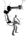
【課題】ロボットを手動制御するオペレータに対して高精度な機械的補助を高い安全性で行い、人間工学的な問題、安全性の問題および効率性の問題を良好に解消する、補助装置を提供する。【解決手段】ロボットのアームBに装備される補助装置は、ロボットのアームBが、端部にツールmを保持し、オペレータHによって制御されるものである。補助装置は、アームBの延長上で、ボール−アンド−ソケットジョイントR3を介して、ツールmに対してオフセットするように取り付けられる制御用のハンドル1と、ツールmの方向及び力を操作するためにオペレータHによって加えられる意図的な力をハンドル1から連続的に検出する、ロボットに接続される力センサ4と、を備える。【選択図】図1AProvided is an auxiliary device that performs high-precision mechanical assistance to an operator who manually controls a robot with high safety and satisfactorily solves ergonomic problems, safety problems, and efficiency problems. To do. An auxiliary device installed in an arm B of a robot is one in which the arm B of the robot holds a tool m at an end and is controlled by an operator H. The auxiliary device operates on the extension of the arm B to control the direction and force of the tool m, and the control handle 1 mounted so as to be offset with respect to the tool m via the ball-and-socket joint R3. And a force sensor 4 connected to the robot for continuously detecting the intentional force applied by the operator H from the handle 1. [Selection] Figure 1A
Description
本発明は、ロボットに用いる手動制御補助装置、その装置を装備した協働ロボット、および当該協働ロボットの使用方法に関する。 The present invention relates to a manual control auxiliary device used for a robot, a collaborative robot equipped with the device, and a method of using the collaborative robot.
特に、仕上げ作業や部品組立作業や機械加工作業の際の、ロボットの制御を補助(l'assistance du pilote d'un robot)する産業用ロボットの分野に適用されるような装置では、複数の方向に大きな力を印加することに加えて高精度も要求される。 In particular, for devices such as those applied in the field of industrial robots that assist in the control of robots during finishing, part assembly and machining operations (l'assistance du pilote d'un robot) In addition to applying a large force, high accuracy is required.
一般的に、上記のような作業は、高度な準備を伴うこと、および、ロボットのアームのバランスが全ての向きで維持されていることをオペレータが継続的に保証しなければならないことにより、従事者に深刻な疲労問題をもたらす。 In general, such work involves high levels of preparation, and the operator must continuously ensure that the arm balance of the robot is maintained in all orientations. Cause serious fatigue problems.
ロボットのアームは高速で動作したり極めて強い加速を生じたりするので、その大きな慣性やツールの荷重によって深刻な事故を招きかねないことから、上述した制約がいっそう厳しく且つ細かく設定される。 Since the robot arm operates at high speed or generates extremely strong acceleration, a serious accident may be caused by the large inertia or the load of the tool, so that the above-described restrictions are set more severely and finely.
さらに、オペレータは、アームの端部に装着されたツールの適切な動作を監視すると共に、作業区域の機械的環境(a l'environnement mecanique)に対して当該ツールが正確に位置しているか否かについても監視しなければならず、長時間にわたって極めて入念に注意を払わなければならない。そのため、上述した作業の快適性は極めて低くなる。 In addition, the operator shall monitor the proper operation of the tool attached to the end of the arm and check whether the tool is correctly positioned with respect to the mechanical environment of the work area (a l'environnement mecanique). Must also be monitored, and very careful attention must be paid over a long period of time. Therefore, the comfort of the above-described work is extremely low.
本発明の目的は、オペレータに対して高精度な機械的補助を高い安全性で提供することができる解決手段を提案することにより、上述したような人間工学的な問題、安全性の問題および効率性の問題を良好に解消することである。 The object of the present invention is to propose a solution capable of providing high-precision mechanical assistance to an operator with high safety, and thus to solve the above-mentioned ergonomic problems, safety problems and efficiency. To solve the problem of sexuality.
本発明において、上記の目的は、ツールに対してオフセットするようにしてボール−アンド−ソケットジョイントを介してロボットのアームに取り付けられる制御用のハンドルと、前記ツールの方向及び力を操作するためにオペレータによって加えられる意図的な力を前記ハンドルから連続的に検出する、前記ロボットに接続される力センサとを備える補助装置を使用することによって達成される。 In the present invention, the above object is to operate a control handle attached to a robot arm via a ball-and-socket joint so as to be offset with respect to the tool, and to operate the direction and force of the tool. This is accomplished by using an auxiliary device comprising a force sensor connected to the robot that continuously detects intentional forces applied by an operator from the handle.
有利な一構成では、前記ツールがモータに接続されて駆動される。このモータは、前記制御用のハンドルを保持して前記ボール−アンド−ソケットジョイントに上流側で接続されるマンドレルに取り付けられる。 In one advantageous configuration, the tool is connected to and driven by a motor. The motor is attached to a mandrel that holds the control handle and is connected upstream to the ball-and-socket joint.
有利な他の構成では、前記力センサが、前記ハンドルと前記アームの前記端部との間に配置される。 In another advantageous configuration, the force sensor is arranged between the handle and the end of the arm.
好ましくは、前記補助装置は、さらに、前記ハンドルと前記ツールとの間に介装される振動絶縁要素を備える。 Preferably, the auxiliary device further includes a vibration isolation element interposed between the handle and the tool.
本発明の第1の変形例において、前記制御用のハンドルは、前記ツールの動作中にオペレータから命令及び/又はトラブル(troubles)を連続的に検出する状態センサを具備する。 In a first variant of the invention, the control handle comprises a state sensor that continuously detects commands and / or troubles from the operator during operation of the tool.
他の変形例において、前記ハンドルは、オペレータの手の有無を検出する検出手段を具備する。 In another modification, the handle includes detection means for detecting the presence or absence of an operator's hand.
詳細な一構成では、前記状態センサが、停止命令、開始命令およびオペレータの手の震えを検出する。 In one detailed configuration, the status sensor detects a stop command, a start command, and an operator's hand tremor.
好ましくは、前記状態センサは、前記ロボットのアームの動作速度を制限する制限手段に接続される。 Preferably, the state sensor is connected to a limiting unit that limits the operation speed of the robot arm.
有利な一構成では、前記ハンドルが、前記状態センサに接続され、指の圧力を感知可能な少なくとも1つのプッシュボタンを具備する。 In one advantageous configuration, the handle comprises at least one push button connected to the condition sensor and capable of sensing finger pressure.
好ましくは、前記ハンドルは、安全PLC(プログラマブル ロジック コントローラ)またはPSS(プログラマブル セーフティ システム)(un automate de securite)に直接作用する。 Preferably, the handle acts directly on a safety PLC (programmable logic controller) or PSS (programmable safety system) (unautomate de securite).
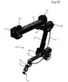
本発明の他の目的は、アームを備える協働ロボットであって、前記アームが端部にツールを保持すると共に、当該アームに本発明にかかる前記補助装置を装備し、さらに、当該アームがほぼC字形状である協働ロボットを提供することである。 Another object of the present invention is a collaborative robot including an arm, the arm holding a tool at an end thereof, the arm being equipped with the auxiliary device according to the present invention, and the arm being substantially It is to provide a collaborative robot that is C-shaped.
本発明のさらなる他の目的は、前記協働ロボットの使用方法であって、オペレータが、前記ロボットのアームに取り囲まれ、当該アームの端部に位置し、前記制御用のハンドルのみを用いて手動で前記ロボットを駆動する、協働ロボットの使用方法を提供することである。 Still another object of the present invention is a method for using the cooperating robot, wherein an operator is surrounded by an arm of the robot, is located at an end of the arm, and is manually operated using only the control handle. To provide a method of using a collaborative robot that drives the robot.
本発明にかかる前記補助装置は、前記ロボットのアームに直接装備されて、作業の実行中に前記アームの動作を制御しようとする前記オペレータの意図を直接検出するので、機械の作業を安全なものにすることができる。 The auxiliary device according to the present invention is directly mounted on the arm of the robot, and directly detects the intention of the operator who wants to control the operation of the arm during the work, so that the work of the machine is safe. Can be.
また、前記補助装置にオペレータの手が直接触れるので、手が離れたり、単に手が震えただけであっても(simple crispation)、それを感知して結果として不測の困難性を検出することで、前記ロボットのアームを停止させることが十分できる。これにより、特殊な緊急停止部材を設ける必要性がなくなる。 In addition, since the operator's hand directly touches the auxiliary device, even if the hand is released or simply shakes the hand (simple crispation), it is detected and the unexpected difficulty is detected as a result. It is sufficient to stop the robot arm. This eliminates the need for a special emergency stop member.
したがって、本発明にかかる前記補助装置により、オペレータの機械的な力を制御して増幅しながら、人間の腕の作業と比べて同様の速度で前記ツールの作業を行うことを保証する。 Therefore, the auxiliary device according to the present invention guarantees that the work of the tool is performed at the same speed as the work of the human arm while controlling and amplifying the mechanical force of the operator.
また、前記補助装置は前記ロボットのアームの一端において、位置をずらして配置するいわゆるオフセット配置とされる(le dispositif est deporte a l'extremite du bras)ので、オペレータの手の位置を、前記ツールから遠ざけることができる。これにより、オペレータの手が特に高速回転で生じる振動に直接曝されないので、快適性が著しく向上する。 Further, since the auxiliary device has a so-called offset arrangement in which one end of the robot arm is shifted in position (le dispositif est deporte a l'extremite du bras), the position of the operator's hand can be determined from the tool. You can keep away. This significantly improves comfort because the operator's hand is not directly exposed to vibrations, especially at high speeds.
このように、人間の腕と同様の速度で作業を実行することができるので、仕事の快適性や仕上がりが向上する。 As described above, the work can be executed at the same speed as that of the human arm, so that the comfort and finish of the work are improved.
さらに、本発明にかかる前記補助装置により、前記ロボットの直近に従事者を位置させても事故のリスクを伴わずに済むので、特に保守作業を簡単に実行できるようになる。 Furthermore, with the auxiliary device according to the present invention, even if a worker is positioned in the immediate vicinity of the robot, there is no risk of an accident, so maintenance work can be particularly easily performed.
本発明は、添付の図面を参照しながら以下の説明を読むことで、より詳しく理解することができる。 The invention can be better understood by reading the following description with reference to the accompanying drawings.
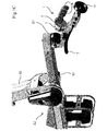
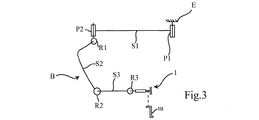
図1A、図1B、図1C及び図3に示す協働ロボットは、従来のものと同じく、一端部が仕切壁(cloison)またはベースEに留められて他端部でモータ駆動のツールmを保持するアームBを備えている。アームBは、まるで人間の腕のように、ピボットP1,P2および/またはボール−アンド−ソケットジョイントR1,R2,R3により互いに関節を有して回動可能に連結された(articules)複数のセクションまたはセグメントS1,S2,S3で構成されている。 The cooperative robot shown in FIGS. 1A, 1B, 1C, and 3 is held at one end by a cloison or base E and holds a motor-driven tool m at the other end, as in the conventional robot. Arm B is provided. Arm B is a plurality of sections articules articulated by pivots P1, P2 and / or ball-and-socket joints R1, R2, R3, just like a human arm. Or it is comprised by segment S1, S2, S3.
アームBには、ツールmを用いて高精度作業を実行するオペレータHを補助する本発明にかかる補助装置が装備されている。 The arm B is equipped with an auxiliary device according to the present invention that assists an operator H who performs high-precision work using the tool m.
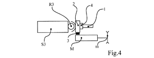
この補助装置は、アームBにボール−アンド−ソケットジョイントR3を介して取り付けられた制御用のハンドル1を備える。ボール−アンド−ソケットジョイントR3は人間の手首のように機能し、ハンドル1の上流側にあるセグメントS3が人間の前腕と同等に機能する。
This auxiliary device includes a
操縦桿(manche)の形態をしたハンドル1は、アームBのセグメントS3の延長上で、ボール−アンド−ソケットジョイントR3を介して設けられており、ハンドル1の上流側に接続されたマンドレル2に装着されて、ツールmに対し位置をずらしたオフセット状態で配置されている。
A
これにより、ハンドル1とオペレータHの前腕とがツールmを保持する部材に対して平行に位置することになるので、オペレータHの作業が容易になり、かつ、操作の精度も向上する。
As a result, the
マンドレル2は、ツールmのモータMを直接保持する(図4)か、あるいは、モータMとツールmとの間でモータの運動を伝達する伝達手段T(図1A、図1B及び図1C)を保持する。後者の場合、モータMはロボットのアームに組み込まれる。
The
任意で、ハンドル1に対する振動を絶縁する振動絶縁要素3が、当該ハンドル1とツールmとの間に介装されてもよい。
Optionally, a
本発明にかかる補助装置は、さらに、協働ロボットに接続された力センサ4を備え、力センサ4は、ツールmの方向及び力を操作するためにオペレータHから加えられる意図的な力を、ハンドル1から連続的に検出する。
The auxiliary device according to the present invention further includes a force sensor 4 connected to the collaborative robot, and the force sensor 4 generates an intentional force applied from the operator H to operate the direction and force of the tool m. Detect continuously from the
力センサ4は、ハンドル1とアームBの前記一つの端部である他端部との間に配置されている。
The force sensor 4 is disposed between the
ハンドル1には、オペレータHからの命令を連続的に検出する状態センサ(図示せず)も組み込まれている。
The
より具体的に述べると、前記状態センサは、ツールmの動作中のオペレータHからの停止命令と開始命令、および/または、ツールmの動作中のオペレータHからのあらゆるトラブル(aux troubles eventuels de l'operateur (H))に対して応答する。そのようなトラブルとして、例えば、ストレスや取扱いの誤りや事故に関係した手の震え(crispations)が挙げられる。 More specifically, the state sensor may be a stop and start command from the operator H during the operation of the tool m and / or any troubles from the operator H during the operation of the tool m. 'operateur (H)). Such troubles include, for example, stress, mishandling and hand crispations related to accidents.
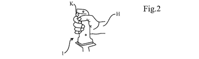
前記状態センサは、そのインターフェースが、ハンドル1に設けられたプッシュボタンKの形態のアクチュエータで構成されているので、オペレータHの手の直接接触を感知することができる。
Since the interface of the state sensor is composed of an actuator in the form of a push button K provided on the
図2に示すように、ハンドル1は、オペレータHの手でジョイスティックのように把持され、作業の状況や性質に応じて変化するオペレータHの指の圧力がプッシュボタンKに加えられる。
As shown in FIG. 2, the
各図に示すツールmは、金属部品(図示せず)をブラッシングおよび/または研磨する作業に適している。 The tool m shown in each figure is suitable for the operation of brushing and / or polishing a metal part (not shown).
前記状態センサは、3種類の主な状態を各々検出することができる。それらは、プッシュボタンKに対する指の圧力がなくなる停止状態、プッシュボタンKが中程度の深さ(ほぼ中央)まで押される正常作業状態、およびプッシュボタンKが最後まで又は少なくとも中央位置を超えて強い圧力(たとえば震えによる加力)で押されるいわゆる重大な状態の3つである。 The state sensor can detect each of three main states. They are a stop state in which finger pressure on the push button K disappears, a normal working state in which the push button K is pushed to a medium depth (approximately center), and a push button K that is strong to the end or at least beyond the center position. There are three so-called critical conditions that are pushed by pressure (for example, force applied by tremor).
制御用のハンドル1は、それに組み込まれた前記状態センサを介して、安全PLC(プログラマブルロジック コントローラ)またはPSS(プログラマブルセーフティ システム)(un automate de securite)に作用する。 The control handle 1 acts on a safety PLC (programmable logic controller) or PSS (programmable safety system) (unautomate de securite) via the state sensor incorporated therein.
一変形例において、ハンドル1には、更にオペレータHの手の有無を検出するための前記安全PLCに接続された検出手段が設けられる。
In a variant, the
前記検出手段は、ハンドル1の表面に設けられた、オペレータHの手の接触を感知可能な薄膜要素であるか、あるいは、ハンドル1の把持部に設けられたさらなるキーボタン(touche)で構成される。
The detection means is a thin film element provided on the surface of the
このように、オペレータHは手をハンドル1に置いて前記状態センサに感知させると共に、合わせて手動でハンドル1を動かして力センサ4にも力を作用させるだけでよいので、前記補助装置の動作は極めて直観的である。
In this way, the operator H only has to place the hand on the
これらのセンサから供給される信号がコンピュータに送信されて、当該コンピュータがロボットのアームBの動作を指令し制御する。これにより、アームBは、自身の慣性にかかわらず、オペレータHの手の意図に対して、十分に融通良くかつ忠実に、極めて正確に従うことができる。 Signals supplied from these sensors are transmitted to the computer, and the computer commands and controls the operation of the arm B of the robot. This allows the arm B to follow the intentions of the hand of the operator H sufficiently flexibly and faithfully and very accurately regardless of its own inertia.
これら2つのセンサは、オペレータHの手と接触するように又はオペレータHの手の近傍に配置されるので、衝突や衝撃のリスクを抑えながらアームBの直ぐ傍にオペレータHを位置させることができる。 Since these two sensors are arranged so as to come into contact with the operator H's hand or in the vicinity of the operator H's hand, the operator H can be positioned right next to the arm B while suppressing the risk of collision and impact. .
オペレータHがハンドル1を離すと、前記ロボットは自動的に且つ即座に停止する。これは、ハンドル1におけるオペレータHの手が震えた場合にも同様である。
When the operator H releases the
オペレータHの指の圧力が許容範囲内にあるとき、前記ロボットは利用可能であるが、その動作速度は制御され規制される。 When the pressure of the finger of the operator H is within an allowable range, the robot can be used, but its operation speed is controlled and regulated.
このような条件下により、オペレータHは安全に補助されて、極めて低い振動レベルで作業しながら自身の力(efforts)を調節された範囲内で増幅することができる。 Under these conditions, the operator H can safely assist and amplify his / her efforts within a controlled range while working at very low vibration levels.
上記のような人間工学的品質は、ハンドル1が適切な外形(profil)を有し、アームBがC字形状であることによってもさらに向上しうる。アームBをC字形状とすることにより、オペレータHは、前記セグメントまたはセクションを背後に配置することで、当該アームBに巻回されるか又は取り囲まれることができる。
The ergonomic quality as described above can be further improved by the
好ましくは、前記状態センサは、前記ロボットのアームBの動作速度を制限する制限手段に接続されている。これにより、唐突な動作を防ぐことができる。 Preferably, the state sensor is connected to a limiting unit that limits an operation speed of the arm B of the robot. Thereby, sudden operation can be prevented.
Claims (12)
前記アーム(B)の延長上で、ボール−アンド−ソケットジョイント(R3)を介して、前記ツール(m)に対してオフセットするように取り付けられた制御用のハンドル(1)と、
前記ツールの方向及び力を操作するためにオペレータによって加えられる意図的な力を、前記ハンドル(1)から連続的に検出する、前記ロボットに接続される力センサ(4)と、
を備えることを特徴とする、補助装置。 An auxiliary device equipped with an arm (B) of a robot holding a tool (m) at an end and controlled by an operator (H),
A control handle (1) mounted on the extension of the arm (B) via a ball-and-socket joint (R3) to be offset with respect to the tool (m);
A force sensor (4) connected to the robot that continuously detects from the handle (1) an intentional force applied by an operator to manipulate the direction and force of the tool;
An auxiliary device comprising:
前記ハンドル(1)と前記ツール(m)との間に介装される振動絶縁要素(3)、
を備えることを特徴とする、補助装置。 The auxiliary device according to any one of claims 1 to 3, further comprising:
A vibration isolation element (3) interposed between the handle (1) and the tool (m);
An auxiliary device comprising:
前記アーム(B)が、ほぼC字形状であることを特徴とする、協働ロボット。 It is a collaborative robot comprising an arm (B), the arm (B) holding the tool (m) at its end and equipped with the auxiliary device according to any one of claims 1 to 10. And
The cooperative robot characterized in that the arm (B) is substantially C-shaped.
オペレータ(H)が、前記ロボットのアーム(B)に取り囲まれ、当該アーム(B)の端部に位置し、
前記制御用のハンドル(1)のみを用いて手動で前記ロボットを駆動する、
ことを特徴とする、協働ロボットの使用方法。 It is a usage method of the cooperation robot of Claim 11, Comprising:
An operator (H) is surrounded by the arm (B) of the robot and is located at the end of the arm (B),
Driving the robot manually using only the control handle (1),
A method of using a collaborative robot.
Applications Claiming Priority (3)
| Application Number | Priority Date | Filing Date | Title |
|---|---|---|---|
| FR1252694A FR2988320B1 (en) | 2012-03-26 | 2012-03-26 | MANUAL CONTROL ASSIST DEVICE FOR ROBOT |
| FR1252694 | 2012-03-26 | ||
| PCT/EP2013/056321 WO2013144103A1 (en) | 2012-03-26 | 2013-03-25 | Manually controlled assistance device for a robot |
Publications (1)
| Publication Number | Publication Date |
|---|---|
| JP2015511544A true JP2015511544A (en) | 2015-04-20 |
Family
ID=47997507
Family Applications (1)
| Application Number | Title | Priority Date | Filing Date |
|---|---|---|---|
| JP2015502288A Pending JP2015511544A (en) | 2012-03-26 | 2013-03-25 | Manual control aid for robots |
Country Status (6)
| Country | Link |
|---|---|
| US (1) | US20150051732A1 (en) |
| EP (1) | EP2830834A1 (en) |
| JP (1) | JP2015511544A (en) |
| BR (1) | BR112014023839A8 (en) |
| FR (1) | FR2988320B1 (en) |
| WO (1) | WO2013144103A1 (en) |
Cited By (7)
| Publication number | Priority date | Publication date | Assignee | Title |
|---|---|---|---|---|
| JP2014184538A (en) * | 2013-03-25 | 2014-10-02 | Denso Wave Inc | Arm operation method and arm operation device |
| JP2014184537A (en) * | 2013-03-25 | 2014-10-02 | Denso Wave Inc | Arm operation method and arm operation device |
| DE102017204211A1 (en) | 2016-03-17 | 2017-09-21 | Kabushiki Kaisha Yaskawa Denki | ROBOT CONTROL AND ROBOT CONTROL PROCEDURES |
| KR101799057B1 (en) * | 2016-05-27 | 2017-11-17 | 재단법인대구경북과학기술원 | Auxiliary device of active exercise for upper extremity |
| JP2018506321A (en) * | 2015-01-09 | 2018-03-08 | ストライカー・コーポレイション | Separate force / torque sensor assembly for force control robot |
| US10548677B2 (en) | 2015-12-16 | 2020-02-04 | Olympus Corporation | Medical manipulator system, control device of medical manipulator system, and control method of medical manipulator system |
| CN114670223A (en) * | 2022-03-04 | 2022-06-28 | 天津新松机器人自动化有限公司 | Robot control handle with safety switch and method |
Families Citing this family (12)
| Publication number | Priority date | Publication date | Assignee | Title |
|---|---|---|---|---|
| FR2983762B1 (en) * | 2011-12-09 | 2014-01-10 | Commissariat Energie Atomique | METHOD FOR CONTROLLING A ROBOT AND STEERING SYSTEM USING SUCH A METHOD |
| CN103640022A (en) * | 2013-11-13 | 2014-03-19 | 北京卫星环境工程研究所 | Flexible follow-up control method for spacecraft mechanical arm |
| FR3026335A1 (en) * | 2014-09-29 | 2016-04-01 | Robotiques 3 Dimensions | EXOSQUELET WITH TOOL HOLDER AND METHOD OF USING SUCH EXOSQUELET. |
| US10499999B2 (en) | 2014-10-09 | 2019-12-10 | Auris Health, Inc. | Systems and methods for aligning an elongate member with an access site |
| CN106737630A (en) * | 2015-11-11 | 2017-05-31 | 福州严创环境科技有限公司 | A kind of portable Furnace-front mechanical hand |
| CA3054744A1 (en) * | 2017-03-26 | 2018-10-04 | James Brent Klassen | Robot arm |
| WO2019005696A1 (en) | 2017-06-28 | 2019-01-03 | Auris Health, Inc. | Electromagnetic distortion detection |
| EP3644885B1 (en) | 2017-06-28 | 2023-10-11 | Auris Health, Inc. | Electromagnetic field generator alignment |
| US10464209B2 (en) | 2017-10-05 | 2019-11-05 | Auris Health, Inc. | Robotic system with indication of boundary for robotic arm |
| US10016900B1 (en) | 2017-10-10 | 2018-07-10 | Auris Health, Inc. | Surgical robotic arm admittance control |
| DE102018206947A1 (en) * | 2018-05-04 | 2019-11-07 | Kuka Deutschland Gmbh | METHOD AND SYSTEM FOR PROGRAMMING A ROBOT PROCESS |
| CN114641252B (en) | 2019-09-03 | 2023-09-01 | 奥瑞斯健康公司 | Electromagnetic Distortion Detection and Compensation |
Family Cites Families (6)
| Publication number | Priority date | Publication date | Assignee | Title |
|---|---|---|---|---|
| US6204619B1 (en) * | 1999-10-04 | 2001-03-20 | Daimlerchrysler Corporation | Dynamic control algorithm and program for power-assisted lift device |
| US6204620B1 (en) * | 1999-12-10 | 2001-03-20 | Fanuc Robotics North America | Method of controlling an intelligent assist device |
| US6385508B1 (en) * | 2000-10-31 | 2002-05-07 | Fanuc Robotics North America, Inc. | Lead-through teach handle assembly and method of teaching a robot assembly |
| JP4792901B2 (en) * | 2005-09-30 | 2011-10-12 | 日産自動車株式会社 | Laser welding apparatus and method, and irradiation apparatus |
| FR2960467B1 (en) * | 2010-06-01 | 2012-07-27 | Robotiques 3 Dimensions | COLLABORATIVE ROBOTICS EQUIPMENT |
| FR2962063B1 (en) * | 2010-07-02 | 2012-07-20 | Commissariat Energie Atomique | ROBOTIC HANDLING ASSISTANCE DEVICE WITH VARIABLE EFFORT INCREASE RATIO |
-
2012
- 2012-03-26 FR FR1252694A patent/FR2988320B1/en not_active Expired - Fee Related
-
2013
- 2013-03-25 WO PCT/EP2013/056321 patent/WO2013144103A1/en active Application Filing
- 2013-03-25 US US14/388,348 patent/US20150051732A1/en not_active Abandoned
- 2013-03-25 JP JP2015502288A patent/JP2015511544A/en active Pending
- 2013-03-25 BR BR112014023839A patent/BR112014023839A8/en not_active IP Right Cessation
- 2013-03-25 EP EP13711907.9A patent/EP2830834A1/en not_active Withdrawn
Cited By (9)
| Publication number | Priority date | Publication date | Assignee | Title |
|---|---|---|---|---|
| JP2014184538A (en) * | 2013-03-25 | 2014-10-02 | Denso Wave Inc | Arm operation method and arm operation device |
| JP2014184537A (en) * | 2013-03-25 | 2014-10-02 | Denso Wave Inc | Arm operation method and arm operation device |
| JP2018506321A (en) * | 2015-01-09 | 2018-03-08 | ストライカー・コーポレイション | Separate force / torque sensor assembly for force control robot |
| US10548677B2 (en) | 2015-12-16 | 2020-02-04 | Olympus Corporation | Medical manipulator system, control device of medical manipulator system, and control method of medical manipulator system |
| DE102017204211A1 (en) | 2016-03-17 | 2017-09-21 | Kabushiki Kaisha Yaskawa Denki | ROBOT CONTROL AND ROBOT CONTROL PROCEDURES |
| US10377038B2 (en) | 2016-03-17 | 2019-08-13 | Kabushiki Kaisha Yaskawa Denki | Robot controller and robot control method |
| DE102017204211B4 (en) | 2016-03-17 | 2022-05-05 | Kabushiki Kaisha Yaskawa Denki | Robot control and robot control method |
| KR101799057B1 (en) * | 2016-05-27 | 2017-11-17 | 재단법인대구경북과학기술원 | Auxiliary device of active exercise for upper extremity |
| CN114670223A (en) * | 2022-03-04 | 2022-06-28 | 天津新松机器人自动化有限公司 | Robot control handle with safety switch and method |
Also Published As
| Publication number | Publication date |
|---|---|
| BR112014023839A8 (en) | 2017-07-25 |
| FR2988320A1 (en) | 2013-09-27 |
| BR112014023839A2 (en) | 2017-06-20 |
| EP2830834A1 (en) | 2015-02-04 |
| WO2013144103A1 (en) | 2013-10-03 |
| US20150051732A1 (en) | 2015-02-19 |
| FR2988320B1 (en) | 2015-01-16 |
Similar Documents
| Publication | Publication Date | Title |
|---|---|---|
| JP2015511544A (en) | Manual control aid for robots | |
| US10564635B2 (en) | Human-cooperative robot system | |
| US10423154B2 (en) | Robot system including force-controlled pushing device | |
| JP6100727B2 (en) | Human cooperative industrial robot with read-through function | |
| KR20180041218A (en) | Remote control robot system | |
| US20110313573A1 (en) | Method and device for command input in a controller of a manipulator | |
| JP6959762B2 (en) | Remote control robot system | |
| KR19990044591A (en) | Robot Teaching Device | |
| CN109834717B (en) | Robot operating device | |
| JP7074962B2 (en) | Robot teaching system | |
| WO2017174204A2 (en) | Construction machine | |
| US20220388156A1 (en) | Maintaining free-drive mode of robot arm for period of time | |
| JP2009034754A (en) | Power assist apparatus and its control method | |
| US20150133034A1 (en) | Machine tool comprising a spindle head and method for positioning a spindle head of a machine tool | |
| JP6240422B2 (en) | Robot control system and robot control method | |
| JP5202935B2 (en) | Teaching device | |
| JP3632268B2 (en) | Robot direct teaching device | |
| JP6271835B2 (en) | Robot hand guide system | |
| CN111356560B (en) | Operating device | |
| US10639799B2 (en) | Robot system | |
| KR20130009316A (en) | Apparatus for controlling robot with embedded physical impact sensor and method for controlling robot using the same | |
| JP5446573B2 (en) | Robot control apparatus and robot operation device | |
| JP3178813B2 (en) | Remote control device | |
| US20220379463A1 (en) | Safe activation of free-drive mode of robot arm | |
| JPH0985658A (en) | Control system for robot |
Legal Events
| Date | Code | Title | Description |
|---|---|---|---|
| A521 | Request for written amendment filed |
Free format text: JAPANESE INTERMEDIATE CODE: A523 Effective date: 20150216 |