JP2015510586A - 3D zoom imaging device - Google Patents
3D zoom imaging device Download PDFInfo
- Publication number
- JP2015510586A JP2015510586A JP2014554728A JP2014554728A JP2015510586A JP 2015510586 A JP2015510586 A JP 2015510586A JP 2014554728 A JP2014554728 A JP 2014554728A JP 2014554728 A JP2014554728 A JP 2014554728A JP 2015510586 A JP2015510586 A JP 2015510586A
- Authority
- JP
- Japan
- Prior art keywords
- camera
- distance
- tof
- feature
- far
- Prior art date
- Legal status (The legal status is an assumption and is not a legal conclusion. Google has not performed a legal analysis and makes no representation as to the accuracy of the status listed.)
- Pending
Links
Images


Classifications
-
- H—ELECTRICITY
- H04—ELECTRIC COMMUNICATION TECHNIQUE
- H04N—PICTORIAL COMMUNICATION, e.g. TELEVISION
- H04N13/00—Stereoscopic video systems; Multi-view video systems; Details thereof
-
- G—PHYSICS
- G01—MEASURING; TESTING
- G01S—RADIO DIRECTION-FINDING; RADIO NAVIGATION; DETERMINING DISTANCE OR VELOCITY BY USE OF RADIO WAVES; LOCATING OR PRESENCE-DETECTING BY USE OF THE REFLECTION OR RERADIATION OF RADIO WAVES; ANALOGOUS ARRANGEMENTS USING OTHER WAVES
- G01S17/00—Systems using the reflection or reradiation of electromagnetic waves other than radio waves, e.g. lidar systems
- G01S17/02—Systems using the reflection of electromagnetic waves other than radio waves
- G01S17/06—Systems determining position data of a target
- G01S17/08—Systems determining position data of a target for measuring distance only
- G01S17/10—Systems determining position data of a target for measuring distance only using transmission of interrupted, pulse-modulated waves
-
- G—PHYSICS
- G01—MEASURING; TESTING
- G01S—RADIO DIRECTION-FINDING; RADIO NAVIGATION; DETERMINING DISTANCE OR VELOCITY BY USE OF RADIO WAVES; LOCATING OR PRESENCE-DETECTING BY USE OF THE REFLECTION OR RERADIATION OF RADIO WAVES; ANALOGOUS ARRANGEMENTS USING OTHER WAVES
- G01S17/00—Systems using the reflection or reradiation of electromagnetic waves other than radio waves, e.g. lidar systems
- G01S17/87—Combinations of systems using electromagnetic waves other than radio waves
-
- G—PHYSICS
- G01—MEASURING; TESTING
- G01S—RADIO DIRECTION-FINDING; RADIO NAVIGATION; DETERMINING DISTANCE OR VELOCITY BY USE OF RADIO WAVES; LOCATING OR PRESENCE-DETECTING BY USE OF THE REFLECTION OR RERADIATION OF RADIO WAVES; ANALOGOUS ARRANGEMENTS USING OTHER WAVES
- G01S17/00—Systems using the reflection or reradiation of electromagnetic waves other than radio waves, e.g. lidar systems
- G01S17/88—Lidar systems specially adapted for specific applications
- G01S17/89—Lidar systems specially adapted for specific applications for mapping or imaging
- G01S17/894—3D imaging with simultaneous measurement of time-of-flight at a 2D array of receiver pixels, e.g. time-of-flight cameras or flash lidar
-
- H—ELECTRICITY
- H04—ELECTRIC COMMUNICATION TECHNIQUE
- H04N—PICTORIAL COMMUNICATION, e.g. TELEVISION
- H04N13/00—Stereoscopic video systems; Multi-view video systems; Details thereof
- H04N13/20—Image signal generators
- H04N13/204—Image signal generators using stereoscopic image cameras
- H04N13/239—Image signal generators using stereoscopic image cameras using two 2D image sensors having a relative position equal to or related to the interocular distance
Abstract
撮像装置のアクティブスペースを与えるようにオーバーラップする固定された広角及び狭角FOVをそれぞれ有した2つのカメラと、カメラによって与えられる距離、並びにアクティブスペースの近方、中間、及び遠方区域への分割に応じてアクティブスペース内の特徴までの距離を決定する制御器と、を備える3D撮像装置。【選択図】図1Two cameras, each with a fixed wide-angle and narrow-angle FOV that overlap to give the active space of the imaging device, and the distance provided by the cameras, and the division of the active space into near, middle, and far areas And a controller for determining a distance to the feature in the active space according to the 3D imaging device. [Selection] Figure 1
Description
[0001] 物体がカメラから遠ざかるにつれて、カメラがその物体を撮像する光センサーにおいて当該物体を見込む角度は小さくなり、カメラが光センサー上に投射する当該物体の像のサイズとその像により覆われる光センサーのピクセル数は減少する。像のサイズ及びその像が投射されるピクセル数の減少と共に、当該物体の特徴の解像度は小さくなり、物体の細部は見分けにくくなるだろう。ズーム機能を提供するカメラの光学系は、物体がカメラから遠ざかるにつれて「ズームイン」されて、カメラの光センサーにおいて当該物体を見込む角度を維持又は増大させるように、調整可能である。物体にズームインすることで、カメラが光センサー上に合焦させる当該物体の像が拡大され、その物体の撮像される特徴の解像度が向上する。 [0001] As the object moves away from the camera, the angle at which the camera looks at the object in the optical sensor that captures the object decreases, and the size of the image of the object that the camera projects on the optical sensor and the light that is covered by the image The number of pixels in the sensor is reduced. As the size of the image and the number of pixels onto which the image is projected, the resolution of the object's features will decrease and the details of the object will be difficult to distinguish. The optics of the camera providing the zoom function can be adjusted to “zoom in” as the object moves away from the camera to maintain or increase the angle at which the object is viewed by the camera's light sensor. By zooming in on the object, the image of the object that the camera focuses on the optical sensor is enlarged, and the resolution of the imaged feature of the object is improved.
[0002] カメラのズーム調整は、典型的には、カメラの光学系内のレンズ又はレンズ群を動かしてレンズの相対位置、したがって光学系の焦点距離を変化させる機構システムによって提供される。当該システムは、相対的に長い焦点距離と、相対的に小さい視野角により特徴付けられる視野(FOV)とをカメラに与えるようにレンズを動かして、物体にズームインし、カメラが得るその物体の像を拡大する。当該システムは、相対的に短い焦点距離と相対的に広角のFOVをカメラに与えるようにレンズを動かして、物体を「ズームアウト」し、カメラが得るその物体の像を縮小する。 [0002] Camera zoom adjustment is typically provided by a mechanism system that moves a lens or lens group within the camera's optical system to change the relative position of the lens, and thus the focal length of the optical system. The system moves the lens to give the camera a relatively long focal length and a field of view (FOV) characterized by a relatively small viewing angle, zooming in on the object, and an image of that object that the camera obtains To enlarge. The system moves the lens to provide the camera with a relatively short focal length and a relatively wide angle FOV to “zoom out” the object and reduce the image of that object that the camera obtains.
[0003] カメラのFOVは、当該カメラの光学中心から伸びる立体角により区画され、その内部の点がカメラの光学系によりカメラの光センサー上に結像される、空間の領域である。ほとんどの撮像目的におけるFOVのサイズは、水平視野角と垂直視野角によって測るのが便利である。水平視野角及び垂直視野角は、カメラの光学中心から伸び、FOVに含まれ、地面に対してそれぞれ平行及び直角な平面においてカメラの光軸と同一面にある2本の直線の間の最大角度である。 [0003] The FOV of a camera is an area of space that is partitioned by a solid angle extending from the optical center of the camera, and an internal point is imaged on the optical sensor of the camera by the camera optical system. The size of the FOV for most imaging purposes is conveniently measured by the horizontal viewing angle and the vertical viewing angle. The horizontal and vertical viewing angles are the maximum angles between two straight lines that extend from the optical center of the camera and are included in the FOV and are coplanar with the optical axis of the camera in planes parallel and perpendicular to the ground, respectively. It is.
[0004] ズームインは、カメラが撮像するシーン内の物体の像を拡大する一方で、カメラのFOVの視野角を減少させもし、その結果として、撮像されるシーンのサイズと、カメラが撮像することが可能なカメラの周囲環境部分を小さくする。ズームアウトは、カメラが撮像するシーン内の物体の像を縮小する一方で、カメラのFOVの視野角を増大させもし、その結果として、撮像されるシーンのサイズと、カメラが撮像することが可能なカメラの周囲環境部分を大きくする。 [0004] Zooming in enlarges the image of an object in the scene captured by the camera, while also reducing the FOV viewing angle of the camera, resulting in the size of the scene being captured and the camera capturing. Reduce the surrounding environment of the camera that can be used. Zooming out reduces the image of the object in the scene captured by the camera, while also increasing the FOV viewing angle of the camera, so that the size of the captured image and the camera can capture The surrounding environment of a large camera.
[0005] 例えば人物のジェスチャーを追跡してその人物をコンピューターとインターフェイスするなどの多くのアプリケーションにとって、当該人物を撮像するカメラが、以降において「アクティブスペース」と称される相対的に大きな空間体積にわたって満足のいく程度の解像度で人物を撮像することが有利である。例えば、人物の全身の動きに応答するボクシングゲーム又は運動を要するゲームなどの、以降で全身3次元(3D)ゲームとも称されるコンピューターゲームと人物をインターフェイスするために、カメラが当該人物を実質的にアクティブスペース内のあらゆる場所において満足のいく解像度で撮像することが有利であり得る。アクティブスペースは、例えば、およそ1m(メートル)に等しいカメラ近くの距離から、およそ3mに等しいカメラから遠い距離まで広がる「長さ」を有してよい。アクティブスペースの長さにわたって有利な画像解像度を提供するために、カメラ光学はズーム調整可能に構成されることができる。 [0005] For many applications, such as tracking a person's gestures and interfacing the person with a computer, the camera that images the person has a relatively large spatial volume, hereinafter referred to as "active space". It is advantageous to image a person with a satisfactory resolution. For example, in order to interface a person with a computer game, hereinafter referred to as a whole body three-dimensional (3D) game, such as a boxing game that responds to the movement of the person's whole body or a game that requires exercise, the camera effectively It may be advantageous to image at a satisfactory resolution everywhere in the active space. The active space may have, for example, a “length” that extends from a distance near the camera equal to approximately 1 m (meters) to a distance far from the camera equal to approximately 3 m. In order to provide advantageous image resolution over the length of the active space, the camera optics can be configured to be zoom adjustable.
[0006] 3Dゲームのプレイ中に人物のジェスチャー又は動きを追跡するための人物撮像は、その人物の特徴及び任意選択としてその人物の環境の特徴までの距離を取得する3Dカメラ、例えば三角測量3Dカメラや飛行時間(TOF)3Dカメラを用いて有利に行われる。3Dカメラによって人物及び任意選択として人物の環境に対して実質的に同一のある時点で得られる距離は、当該人物を含むシーンの「範囲画像」を与える。3Dカメラは、一般に、当該カメラにより発せられてシーン内の特徴までの距離を測定するように設定された光でシーンを撮像する、アクティブ照明カメラである。 [0006] Human imaging to track a person's gestures or movements during the play of a 3D game is a 3D camera, such as triangulation 3D, that acquires the person's characteristics and optionally the distance to the person's environmental characteristics. This is advantageously done using a camera or a time of flight (TOF) 3D camera. The distance obtained by a 3D camera at a certain point in time that is substantially the same for a person and optionally a person's environment gives a “range image” of the scene containing that person. A 3D camera is generally an active illumination camera that images a scene with light emitted by the camera and set to measure the distance to a feature in the scene.
[0007] 三角測量型3Dカメラは、シーン内の特徴までの距離を、当該カメラが2つの一般には僅かに異なる視点からその特徴を撮像する際の角度から取得する。三角測量カメラは、「構造化光」と称される空間的に変調された光でシーンを照明することができる。飛行時間(TOF)3Dカメラは、当該カメラが撮像するシーン内の特徴までの距離を、それが送出する時間的に変調された光がその特徴まで伝搬してカメラまで戻ってくるのにどのくらいの時間がかかるかを計時することによって取得する。このカメラは、光を通常は非常に短い光パルスで送出し、当該カメラが収集する特徴によって反射されたパルスからの光を撮像して、往復即ち「行き帰り」の光の伝搬時間を測定する。 [0007] A triangulation 3D camera acquires the distance to a feature in the scene from the angle at which the camera images the feature from two generally slightly different viewpoints. Triangulation cameras can illuminate the scene with spatially modulated light called “structured light”. A time-of-flight (TOF) 3D camera measures the distance to a feature in the scene that it captures, and how much time-modulated light it emits propagates back to that feature and returns to the camera. Get it by timing how long it takes. The camera emits light, usually with very short light pulses, and images the light from the pulses reflected by the features it collects to measure the propagation time of the round-trip or “go-and-go” light.
[0008] 3Dカメラにズーム光学を提供することは、概して技術的且つコスト的にチャレンジングである。 [0008] Providing zoom optics to a 3D camera is generally technically and costly challenging.
[0009] 本発明の一実施態様は、第2の3Dカメラの狭角FOVの少なくとも一部分とオーバーラップする広角FOVを有した第1の3Dカメラを備える、以降で「3D撮像装置」とも称される3D撮像システムを提供することに関する。第1及び第2の3DカメラのFOVは、3D撮像装置のアクティブスペースを規定する。3D撮像装置は、第1及び第2の3Dカメラによって与えられる距離情報に応じてアクティブスペース内の特徴の範囲画像を提供するアルゴリズムを実装するための実行可能命令セットを用いてプログラムされるプロセッサーを備える。 [0009] One embodiment of the present invention comprises a first 3D camera having a wide-angle FOV that overlaps at least a portion of a narrow-angle FOV of the second 3D camera, and is hereinafter also referred to as a "3D imaging device". The present invention relates to providing a 3D imaging system. The FOV of the first and second 3D cameras defines the active space of the 3D imaging device. The 3D imager has a processor programmed with an executable instruction set for implementing an algorithm that provides a range image of features in the active space in response to distance information provided by the first and second 3D cameras. Prepare.
[0010] 本発明の一実施態様に従って、アルゴリズムは、以降で「近方カメラ」とも称される第1の3Dカメラにより決定される距離に応じて、相対的に3D撮像装置に近いアクティブスペースの第1の「近方領域」にある特徴までの距離を決定する。アルゴリズムは、以降で「遠方カメラ」とも称される第2の3Dカメラにより決定される距離に応じて、相対的に3D撮像装置から遠いアクティブスペースの第2の「遠方領域」にある特徴までの距離を決定する。近方及び遠方3DカメラのFOVがオーバーラップするアクティブスペースの第3の「オーバーラップ」領域にある特徴までの距離が、両方の3Dカメラによって与えられる距離情報を用いて決定される。 [0010] According to one embodiment of the present invention, an algorithm is used for an active space relatively close to a 3D imaging device, depending on a distance determined by a first 3D camera, also referred to hereinafter as a "near camera". The distance to the feature in the first “near field” is determined. The algorithm is based on the distance determined by the second 3D camera, also referred to as “far camera” hereinafter, to the features in the second “far region” of the active space relatively far from the 3D imaging device. Determine the distance. The distance to the feature in the third “overlap” region of the active space where the FOVs of the near and far 3D cameras overlap is determined using the distance information provided by both 3D cameras.
[0011] 本発明の一実施態様において、近方及び遠方3Dカメラは、それぞれ、以降で近方及び遠方TOFカメラとも称される近方及び遠方TOF 3Dカメラを備える。近方又は遠方TOFカメラのピクセルは、当該ピクセル上に撮像されるアクティブスペース内の特徴のTOFカメラからの距離の測定値を与える、以降で「距離画像」とも称される画像を取得する。本発明の一実施態様に従って、アルゴリズムは、近方又は遠方TOFカメラにおけるどのピクセルが、それぞれ遠方又は近方TOFカメラのピクセルによって撮像されるアクティブスペースの実質的に同一の特徴を撮像するかを決定するように、TOFカメラのピクセルを相関付ける方法を提供する。相関付けは、当該ピクセルにより取得された距離画像が与える距離情報に応じて実施される。任意選択的に、相関付けは、異なるTOFカメラにおけるピクセルがアクティブスペース内の同一の特徴を撮像する確率分布を最大化することによって実施される。 [0011] In one embodiment of the invention, the near and far 3D cameras comprise near and far TOF 3D cameras, also referred to hereinafter as near and far TOF cameras, respectively. A near or far TOF camera pixel obtains an image, hereinafter referred to as a “distance image”, which gives a measure of the distance from the TOF camera of the feature in the active space imaged on that pixel. According to one embodiment of the invention, the algorithm determines which pixels in the near or far TOF camera image substantially the same features of the active space imaged by the pixels of the far or near TOF camera, respectively. Thus, a method for correlating pixels of a TOF camera is provided. Correlation is performed according to distance information given by the distance image acquired by the pixel. Optionally, the correlation is performed by maximizing the probability distribution that pixels in different TOF cameras image the same feature in the active space.
[0012] 一実施態様では、3D撮像装置は、3D撮像装置により供給されるアクティブスペースを照明するための光の強度を、3D撮像装置によって撮像されたアクティブスペース内の特徴の距離に応じて制御する制御器を備える。 In one embodiment, the 3D imaging device controls the intensity of light for illuminating the active space supplied by the 3D imaging device according to the distance of the feature in the active space imaged by the 3D imaging device. A controller is provided.
[0013] 3D撮像装置が広角及び狭角FOVをそれぞれ有した近方及び遠方TOFカメラを備えるように本発明の一実施態様に従って3D撮像装置を構成することによって、3D撮像装置は、相対的に大きなアクティブスペースを有する。3D撮像装置は、従来のズーム光学を用いる必要なく、実質的に当該スペース内のどこにあっても同じ相対的に高い空間解像度で特徴を撮像する。 [0013] By configuring the 3D imaging device according to one embodiment of the present invention so that the 3D imaging device includes a near and far TOF camera having a wide-angle and a narrow-angle FOV, respectively, Has a large active space. The 3D imaging device images features with the same relatively high spatial resolution, wherever it is in the space, without the need to use conventional zoom optics.
[0014] 議論の中では、別段の記載のない限り、本発明の一実施態様に係る特徴の条件又は関係の特性を変更する「実質的に」や「およそ」などの形容詞は、当該条件又は特性が、実施態様の意図された用途による動作にとって容認できる許容範囲内で規定されるということを意味するものと理解される。 [0014] In the discussion, unless stated otherwise, adjectives such as "substantially" and "approximately" that change the characteristics of a feature or the characteristics of a relationship according to one embodiment of the present invention It is understood that the characteristics are defined within acceptable tolerances for operation according to the intended use of the embodiment.
[0015] この概要は、詳細な説明において更に後述される概念からの選抜を簡略な形で導入するために提供される。この概要は、請求された主題の主要な特徴又は本質的な特徴を特定することを意図したものではなく、また、請求された主題の有効範囲を限定するのに用いられることを意図したものでもない。 [0015] This summary is provided to introduce a selection of concepts in a simplified form that are further described below in the detailed description. This summary is not intended to identify key features or essential features of the claimed subject matter, nor is it intended to be used to limit the scope of the claimed subject matter. Absent.
[0016] この段落に引き続いて列挙される添付図を参照して、本発明の実施態様の非限定的な例が以下で説明される。2以上の図に現れる同一の構造、要素、又は部分は、それらが現れる図の全てにおいて全体的に同じ符号を付される。図に示された構成要素及び特徴の寸法は、便宜上及び提示の明確性のために選ばれており、必ずしも縮尺どおりには示されていない。 [0016] Non-limiting examples of embodiments of the present invention are described below with reference to the accompanying figures listed following this paragraph. Identical structures, elements, or parts that appear in more than one figure are generally numbered the same in all of the figures in which they appear. The dimensions of the components and features shown in the figures are chosen for convenience and clarity of presentation and are not necessarily shown to scale.
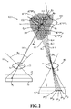
[0020] 詳細な説明の以下の文章では、任意選択的に2つである複数のTOFカメラを備えるTOF 3D撮像装置の態様が、図1を参照して論じられ、図1は、TOF 3D撮像装置の構成要素と、TOFカメラのFOVによって与えられるアクティブスペースとを示す。図2は、図1に示されたTOF 3D撮像装置のアクティブスペースの同一領域にある特徴に対して2つのTOFカメラのピクセルによって得られる距離画像間における幾何学的関係を模式的に示す。当該図は、距離画像により与えられる距離測定値の不確定性と、TOFカメラのピクセルにより与えられる距離測定値の、便宜上ガウシアンであると仮定される頻度分布とを模式的に示す。2つのTOFカメラによって与えられる情報を用いてアクティブスペース内の特徴までの距離を決定するための方法、及び、2つのカメラにおけるどのピクセルが対応し、アクティブスペース内の実質的に同一の特徴を撮像するかを決定するようにピクセルを相関付けるための方法が、図2と、図3A及び3Bに示されたフロー図とを参照して論じられる。 [0020] In the following text of the detailed description, aspects of a TOF 3D imaging device comprising a plurality of TOF cameras, optionally two, are discussed with reference to FIG. 1, where FIG. 1 illustrates TOF 3D imaging. Fig. 2 shows the components of the device and the active space provided by the TOF camera FOV. FIG. 2 schematically illustrates the geometric relationship between range images obtained by two TOF camera pixels for features in the same region of the active space of the TOF 3D imager shown in FIG. The figure schematically shows the uncertainty of the distance measurement given by the distance image and the frequency distribution assumed to be Gaussian for convenience of the distance measurement given by the pixel of the TOF camera. A method for determining the distance to a feature in the active space using information provided by the two TOF cameras, and imaging which pixels in the two cameras correspond to substantially the same feature in the active space A method for correlating pixels to determine whether to do so will be discussed with reference to FIG. 2 and the flow diagrams shown in FIGS. 3A and 3B.
[0021] 図1は、近方TOFカメラ30、遠方TOFカメラ40、及び光源50を備えたTOF 3D撮像装置20の平面図を模式的に示している。TOFカメラの細部は挿入図90に示されている。
FIG. 1 schematically shows a plan view of a TOF
[0022] 近方TOFカメラ30は、近方TOFカメラにより撮像される物体からの光を集光し、その集光光を光センサー32上に結像する、レンズによって代表された光学系31を備えている。光学系31は、相対的に大きな、任意選択として固定の、直線44で区画された水平視野角θNによって特徴付けられる近方TOFカメラの広角FOVを、光センサー32と共に規定する光学中心33及び焦点距離fNを有している。近方TOFカメラ30の広角FOVの視野角θNを規定する直線を指し示している符号44は、近方TOFカメラ30のFOVを参照するのにも用いられ、これは「近方FOV」と称されることもある。光学系31はまた、近方TOFカメラ30をシャッター開状態及びシャッター閉状態にするためのシャッター35も含んでいる。
The
[0023] 同様に、遠方TOFカメラ40は、カメラのFOV内の物体からの光を集光し、その集光光を光センサー42上に結像する、レンズによって代表された光学系41を備えている。当該光学系は、相対的に大きな、任意選択として固定の、直線34で区画された水平視野角θFによって特徴付けられる遠方TOFカメラの狭角FOVを、光センサー42と共に規定する光学中心43及び焦点距離fFを有している。遠方TOFカメラ40の広角FOVの視野角θFを規定する直線を指し示している符号34は、遠方TOFカメラのFOVを参照するのにも用いられ、これは「遠方FOV」と称されることもある。光学系41はまた、遠方TOFカメラをシャッター開状態及びシャッター閉状態にするためのシャッター45も含んでいる。
Similarly, the far-
[0024] 光源50は、近方FOV44及び遠方FOV34内の物体を照明するための光パルス列を放射するように制御器60によって制御可能である。光源50により放射された光パルスは、符号52を付された矩形「パルス」によって模式的に表現されている。光パルス52は、好適な発光ダイオード(LED)及び/又はレーザーによってスペクトルの任意の部分から供給される光を含んでよいが、通常は、近赤外(NIR)の光パルスである。
[0024] The
[0025] 光パルス列中の各光パルス52が近方FOV44及び遠方FOV34内の物体を照明するために光源50によって放射された時点から予め定められた遅延τNDに引き続いて、制御器60は、近方シャッター35を制御して、持続時間τNを有する短い露光期間の間、近方TOFカメラ30をシャッター開状態にする。当該露光期間中に、近方TOFカメラ30に到達する近方FOV44内の特徴により光パルスから反射された光が、レンズ31によって光センサー32上に結像される。結像された光は、近方TOFカメラによって記録され、光パルス52の光が往復で光源50から当該特徴まで伝搬して近方TOFカメラ30まで戻ってくるのにどのくらいの時間がかかるかを測定するのに用いられる。当該特徴が近方TOFカメラから、したがってTOF 3D撮像装置20からどのくらい遠くにあるかを決定するために、往復時間と光速が用いられる。
[0025] Following each predetermined delay τ ND from the time each
[0026] 同様に、各パルス52が光源50によって放射された後の遅延τFDに引き続いて、制御器60は、遠方TOFカメラ40のシャッター45を制御して、持続時間τFを有する短い露光期間の間、遠方TOFカメラをシャッター開状態にする。遠方TOFカメラは、当該露光期間中に遠方TOFカメラに到達する光パルスから反射された光を結像及び記録し、その記録された光を用いてTOF 3D撮像装置20から遠方FOV34内の特徴までの距離を測定する。
[0026] Similarly, following the delay τ FD after each
[0027] 遠方TOFカメラ40は、その狭角FOV34のために、TOF 3D撮像装置20からより遠くにある特徴を近方TOFカメラ30よりも良好な空間解像度で撮像するが、TOF 3D撮像装置20に近い相対的に小さい体積の空間を撮像する。一方、近方TOFカメラ30は、その相対的に広角のFOV44のために、TOF 3D撮像装置20に近い相対的に大きい体積の空間を撮像することが可能であり、密集した特徴を満足のいく空間解像度で撮像するように構成されることができる。
The far-
[0028] 本発明の一実施態様に従って、TOF 3D撮像装置20に有利なアクティブスペースを提供すべく近方FOV44と遠方FOV34を結合するために、また近方TOFカメラ30と遠方TOFカメラ40により与えられる距離情報をどのように用いるかを決定するために、撮像範囲の下側境界と上側境界が、近方TOFカメラ30と遠方TOFカメラ40に対して制定される。近方TOFカメラ30に関する下側範囲境界と上側範囲境界が、それぞれNRLとNRUによって表されることにしよう。近方TOFカメラ30の下側境界と上側境界は、NRL及びNRUと符号付けされた破線によって図1に模式的に示されている。遠方TOFカメラ40に関する下側範囲境界と上側範囲境界がそれぞれFRLとFRUによって表されることにしよう。遠方カメラ40の下側境界と上側境界は、FRL及びFRUと符号付けされた破線によって図1に模式的に示されている。
[0028] In accordance with one embodiment of the present invention, the near FOF 44 and the far
[0029] 視野角θN及びθF、並びに範囲境界NRL、NRU、FRL、及びFRUは、任意選択的に、太い破線22によって模式的に輪郭を描かれたTOF 3D撮像装置20のアクティブスペースを画定する。TOF 3D撮像装置20のアクティブスペースの輪郭を描く破線を符号付けしている符号22は、アクティブスペースを参照するのにも用いられる。
The viewing angles θ N and θ F and the range boundaries NR L , NR U , FR L , and FR U are optionally
[0030] 本発明の一実施態様では、近方TOFカメラ30の広角FOV44の視野角θNは、アクティブスペース22がTOF 3D撮像装置20の近くにおいて有利な幅を有するように決定される。近方上側境界NRU及び遠方上側境界FRU、並びに遠方TOFカメラ40の狭角FOV34の視野角θFは、近方TOFカメラ30と遠方TOFカメラ40がそれぞれ距離NRU及びFRUにおいて実質的に同じ空間解像度で物体を撮像するように決定される。説明的な例として、光センサー32及び42が実質的に同じピクセルサイズを有していると仮定すると、もしtan[θF/2]=(NRU/FRU)tan[θN/2]であれば、近方TOFカメラ30と遠方TOFカメラ40はそれぞれ、距離NRU及びFRUにおいて実質的に同じ空間解像度で物体を撮像する。
In one embodiment of the present invention, the viewing angle θ N of the wide-angle FOV 44 of the
[0031] 数値的な例として、近方TOFカメラ30及び遠方TOFカメラ40が640×480ピクセルのアレイを備えた光センサー32及び42を有しており、当該ピクセルが5.6μm(マイクロメートル)の対角長を有していると想定されたい。NRU=200cm且つFRU=300cmの場合、近方TOFカメラ30と遠方TOFカメラ40は、もしそれらのFOV角θN及びθFがそれぞれおよそ74°及びおよそ53°に等しければ、それぞれ距離200cm及び300cmにおいておよそ0.5cm離れた特徴を解像するだろう。
As a numerical example, the
[0032] 滑らかに連続的なアクティブスペース22を提供し、近方TOFカメラ30及び遠方TOFカメラ40によって与えられる画像の空間的記録を容易化するために、遠方TOFカメラ40の下側境界範囲FRLと近方TOFカメラ30の上側境界範囲NRUは、FRL<NRUであるように決定される。したがって、アクティブスペース22は、3つの区域:近方区域23、中間区域24、及び遠方区域25を含む。
[0032] In order to provide a smooth continuous
[0033] 数値的な例として、アクティブスペース、例えば全身3Dコンピューターゲームをプレイするためのアクティブスペース22が、TOF 3D撮像装置20からおよそ0.80mに等しいNRLから、TOF 3D撮像装置20からおよそ3mに等しいFRUまで有利に広がっていると想定されたい。もしTOF 3D撮像装置20から0.80mにおいてアクティブスペース22がおよそ幅1mであれば、有利には、近方TOFカメラ30は、およそ62.5°に等しい視野角θNを有する。もしTOF 3D撮像装置20から距離NRUにおいてアクティブスペース22が有利におよそ2.5mの幅を有していれば、NRUはおよそ2mに等しく、θF=arctan[θF/2]=arctan((NRU/FRU)tan[θN/2]θF)はおよそ42°に等しい。もし近方TOFカメラ及び遠方TOFカメラが一辺15μmの正方形のピクセルを有しており、距離NRU及びFRUにおいておよそ1cm離れた特徴を解像することが有利に可能であれば、それらの焦点距離fN及びfFは、それぞれおよそ30mm(ミリメートル)及び45mmに有利に等しい。
[0033] As a numerical example, the active space, such as systemic 3D computer games
[0034] 制御器60は、TOF 3D撮像装置20を制御し、下側及び上側境界NRL、NRU、FRL、及びFRU、並びにそれらが区画する区域23、24、及び25に応じて、近方TOFカメラ30と遠方TOFカメラ40により得られた距離画像によって与えられる距離情報を処理する。本発明の一実施態様では、制御器60は、実質的にそれぞれ遠方TOFカメラ40の遅延τFD及び露光期間τFに等しい近方TOFカメラ30の遅延τND及び露光期間の持続時間τNを用いて、TOF 3D撮像装置20を制御する。これらの実質的同等性の条件の下では、両方のTOFカメラは、TOF 3D撮像装置から同じ距離の範囲にわたってアクティブスペース22内の特徴の画像を取得する。
[0034] The
[0035] 本発明の一実施態様では、制御器60は、遠方TOFカメラ40が、遠方FOV34内に存在する特徴の近方TOFカメラからの距離がFRLとFRUの間にある場合にのみ、当該特徴を光源50からの光で撮像するように決定されたτFD及びτFを用いて、遠方TOFカメラ40をシャッター制御する。同様に、制御器は、近方TOFカメラ30が、近方FOV44内に存在する特徴の近方TOFカメラからの距離がNRLとNRUの間にある場合にのみ、当該特徴を光源50からの光で撮像するように決定されたτND及びτFを用いて、近方TOFカメラ30をシャッター制御する。
[0035] In one embodiment of the present invention, the
[0036] 概して、制御器60は、近方TOFカメラ30によってのみ提供される距離画像を用いて、区域23内の特徴に対する満足のいく距離測定値を与えることができる。概して、制御器60は、遠方TOFカメラ40によってのみ提供される距離画像を用いて、区域25内の特徴に対する満足のいく距離測定値を与えることができる。中間区域24に位置している特徴に対して、又はTOFカメラの一方によってもたらされる明らかに無効な若しくは不確かな距離に対しては、制御器は、任意選択的に、近方TOFカメラと遠方TOFカメラの両方によって提供されるデータを使用する。黒丸73、74、及び75は、区域23、24、及び25内の位置にある特徴を模式的に表している。
[0036] In general,
[0037] 距離画像から決定される特徴までの近方TOFカメラ30と遠方TOFカメラ40の双方からの距離に対して、制御器は、TOFカメラのうちの一方を「主」TOFカメラとして指定する。表現上の便宜のため、本発明の一実施態様に従ってTOFカメラからの情報がどのように用いられるのかに関する以下の説明において、文字「C」が主カメラを表す。文字C*はもう一方のカメラを表し、それは「副」カメラと称されることができる。TOF 3D撮像装置20からの距離は、主カメラCのピクセルPj上に撮像された特徴に対して測定されるべきであると考えられる。例として、図2を参照する以下の議論では、主カメラは、近方TOFカメラ30であると想定され、ピクセルPj上に撮像される特徴は、中間区域24に位置する図1に示された特徴74であると想定される。
[0037] For the distance from both the
[0038] 図2は、近方TOFカメラ30及び遠方TOFカメラ40の拡大図と、特徴74が位置している中間区域24の領域100と、特徴74が撮像される主カメラC即ち近方TOFカメラ30の光センサー32上のピクセルPjとを模式的に示している。
FIG. 2 shows an enlarged view of the
[0039] 本発明の一実施態様に従い、特徴74は、空間内の直線、即ち当該特徴から近方TOFカメラ30の光学中心33を通り抜けてピクセルPjと交わる主撮像ライン101とも称される撮像ライン101に沿って存在するように拘束されているものと想定される。特徴74の裾引き(trail)距離は、ピクセルPjによって得られた特徴74の距離画像から決定される距離「dCPj」である。主撮像ライン101に沿った距離「d」は、確率分布関数P(d;dCPj,σj)によって与えられる確率を持つ特徴74の位置における当該撮像ラインに沿った実際の距離であると想定され、ここでσjは試行(trial)距離dCPjに関係した誤差の尺度である。典型的には、ショットノイズ及び読み出しノイズが、裾引き距離に関係した誤差を生じさせる。補助線110及び111の間の撮像ライン101の一区間は、dCPjに関係した誤差の大きさを模式的に表している。図2では、確率分布P(d;dCPj,σj)は、撮像ライン101に沿って示された曲線120により表される、距離dCPjにおいて最大値を有すると共に標準偏差σjを有する正規分布であると想定される。
[0039] According to one embodiment of the present invention, wherein 74 is a straight line in space, i.e.
[0040] 本発明の一実施態様に従い、補助線110及び111の間の距離djmにおける撮像ライン101に沿った複数のM個の領域Rjm(1≦m≦M)のそれぞれについて、もしそれが領域内に位置していたなら領域Rjmが撮像されることになる、遠方TOFカメラ40の光センサー42内のピクセルP* jmが決定される。図2では、Mは恣意的に5に等しく示されている。領域Rjmは、補助線110及び111間の主撮像ライン101の区間に沿って、それぞれRj1、Rj2、…Rj5に対応する距離dj1、dj2、…dj5により符号付けされた菱形アイコンによって模式的に指定されている。
[0040] In accordance with an embodiment of the present invention, for each of a plurality of M regions R jm (1 ≦ m ≦ M) along the
[0041] ピクセルP* jmは、djmから副カメラ即ち遠方TOFカメラ40の光学中心43を通って伸びる、以降で副撮像ラインILmとも称される撮像ラインILmの端に存在している。ピクセルP* jmによって得られる距離画像は、当該ピクセル上に撮像される特徴に対して当該ピクセルに関係した撮像ラインILmに沿った距離dC*P* jmを与え、この距離dC*P* jmは、誤差σ* jmに関係していると想定されたい。距離dC*P* jmは、副撮像ラインILmに沿った距離dC*P* jm(1≦m≦5)により符号付けされた円形アイコンによって図的に表されている。
[0041] Pixel P * jm extends through the
[0042] ピクセルP* jm上に撮像される特徴の撮像ラインILmに沿った距離d* mが当該特徴の実際の距離である確率が、確率分布関数P(d* m;dC*P* jm,σ* jm)によって与えられるとしよう。図2では、例示的な分布P(d* jm;dC*P* jm,σ* jm)が、m=5の場合の正規分布130として示されている。もし主撮像ライン101の副撮像ラインILmとの交点が遠方TOFカメラ40からの撮像ラインILmに沿った距離d* jmに位置しているならば、d* jmがピクセルP* jm上に撮像される特徴の遠方カメラ40からの実際の距離である確率は、P(d* jm;dC*P* jm,σ* jm)である。
The probability that the distance d * m along the imaging line IL m of the feature imaged on the pixel P * jm is the actual distance of the feature is the probability distribution function P (d * m ; dC * P * jm , σ * jm ). In FIG. 2, an exemplary distribution P (d * jm ; dC * P * jm , σ * jm ) is shown as a
[0043] 本発明の一実施態様に従い、制御器60は、主即ち近方TOFカメラ30のピクセルPj上に撮像される特徴、例えば特徴74の距離DCPjが、P(dm;dCPj,σj)・P(d* jm;dC*P* jm,σ* jm)を最大化する距離dm(1≦m≦M)であると判定する。
[0043] According to one embodiment of the present invention,
[0044] 上記の議論では、近方TOFカメラ30が主カメラと指定され、遠方TOFカメラ40が副カメラと指定されたが、距離を決定するための手順は、通常、どちらのカメラが主カメラであるかとは実質的に無関係であるということが留意される。遠方TOFカメラ40が主カメラと指定され、近方TOFカメラが副カメラと指定され、主撮像ライン101が遠方TOFカメラに関係付けられる場合、カメラの役割は反対にすることができる。
[0044] In the above discussion, the
[0045] 図3A及び3Bは、TOF 3D撮像装置20が近方TOFカメラ30及び遠方TOFカメラ40により得られたアクティブスペース22の画像からの情報を処理して、アクティブスペース22内の特徴までの距離を判定し、当該アクティブスペース内の特徴の範囲画像を提供するアルゴリズムのフロー図200を示しており、当該アルゴリズムもまた符号200によって参照される。
[0045] FIGS. 3A and 3B show that the TOF
[0046] ブロック202において、任意選択的に、制御器60は、ズームアウトモード又はズームインモードで動作するようにTOF 3D撮像装置20を調整するか否かを決定する。TOF 3D撮像装置を調整することは、近方TOFカメラ30(広角FOVズームアウトカメラ)又は遠方TOFカメラ40(狭角FOVズームインカメラ)のどちらのカメラが、当該カメラによって供給される距離情報を処理するための主カメラと指定されるかを決定することを含む。図1に関する上記の議論は、アクティブスペース22(図1)内の特徴までの距離を測定する際における主カメラの役割の例を与えている。任意選択的に、どちらのカメラが有利に主カメラと指定されるかを決定するために、制御器60は、近方TOFカメラ30と遠方TOFカメラ40によって供給された距離から、アクティブスペース22の近方区域23、オーバーラップ区域24、及び遠方区域25のそれぞれに存在する関心のある特徴の数を評価する。制御器は、その評価された特徴の数に応じて、ズームイン又はズームアウトを決定する。
[0046] In
[0047] 例えば、もし優勢数の特徴が近方区域23又は遠方区域25にあるならば、制御器60は、主カメラをそれぞれ近方TOFカメラ30によるズームインモード、又は遠方TOFカメラ40によるズームアウトモードで動作させるように、TOF 3D撮像装置20を調整する。任意選択的に、もし優勢数の関心のある特徴が中間区域に存在すると判明したならば、制御器60は、TOF 3D撮像装置を、関心のある特徴の数を評価する前に動作していたズームモードで動作するままにしておくか、又は、予め定められたデフォルトの手順に従ってズームモードを決定する。
[0047] For example, if the dominant number feature is in the
[0048] ブロック204において、制御器60は、光源50によって放射される光パルスの強度をズームモードの選択に合うように設定する。もしズームモードがズームアウトであるならば、制御器は、任意選択的に、TOF 3D撮像装置20に近い近方区域23にある特徴が、光パルスから近方TOFカメラ30及び遠方TOFカメラ40へとそれらTOFカメラ内のピクセルを飽和させる光の量を反射する蓋然性を低減するように、適度なレベルに強度を設定する。もしズームモードがズームインであるならば、制御器60は、任意選択的に、TOF 3D撮像装置20から相対的に遠い遠方区域25にある特徴が、満足のいく撮像にとって十分な光をTOFカメラへ反射しない蓋然性を低減するように、ズームアウトモード向けに選択された前記適度な強度よりも大きく、放射パルスの強度を設定する。中間的な強度が、相対的に多数の関心のある特徴が中間区域24に見出された状況に対して、任意選択的に決定される。
[0048] In
[0049] ブロック206において、制御器は、近方TOFカメラ30又は遠方TOFカメラ40の何れかであり得る主カメラCのピクセルを指定するインデックス「j」をゼロに初期化する。インデックスjは、Jに等しい最大値を有し、Jは近方TOFカメラ30における総ピクセル数を表す。ブロック208において、制御器は、インデックスを1だけ増加させる。ブロック210において、制御器60は、主カメラCのピクセルPjによって得られた距離画像からアクティブスペース22内の特徴に対する裾引き距離dCPjを決定する。判定ブロック212において、制御器60は、ピクセルPj上に撮像された特徴が以降で「C区域」とも称される主カメラCに関係するアクティブスペース22内の区域に位置しているか否かを、dCPjの値が示しているか判定する。即ち、もし近方TOFカメラ30が主カメラCであるならば、C区域は近方区域23(図1)であり、もし遠方TOFカメラ40が主カメラCであるならば、C区域は遠方区域25である。もし撮像された特徴がC区域にあると分かったなら、ブロック214において、制御器は、任意選択的に、距離DCPj=dCPjが、主カメラCのピクセルPj上に撮像された特徴に対する距離であると決定する。
[0049] At
[0050] 制御器は次いで、任意選択的に、ブロック224へ進んで、j=Jであるかどうかを判定する。ここでJは主カメラCにおけるピクセル総数である。もしjがJに等しくなければ、制御器60は、ブロック208へ戻ってインデックスjを1だけ増加させ、続けて次のピクセルP(j+1)上に撮像された特徴についての距離を決定する。もしj=Jならば、制御器60は、主カメラCのピクセルPjに対する距離を決定するための処理を終了し、任意選択的に、ブロック226において、距離DCPj j=1→Jを用いてアクティブスペース22に対する範囲画像を提供する。制御器は次いで、任意選択的に、ブロック228へ進んで処理を終了する。
[0050] The controller then optionally proceeds to block 224 to determine if j = J. Here, J is the total number of pixels in the main camera C. If j is not equal to J,
[0051] 本発明の一実施態様において、もし特徴がC区域に存在しなければ、制御器は、任意選択的に、ピクセルPj上に撮像された特徴が中間区域24に位置していそうかどうかを試行距離dCPjが示しているか、判定ブロック216において判定する。もしそうなら、任意選択的に、ブロック218において、制御器60は、主カメラCと副カメラC*の両方からの距離情報を用いて、Pj上に撮像された特徴に対する距離DCPjを決定する。任意選択的に、制御器は、TOF 3D撮像装置20における近方TOFカメラ30及び遠方TOFカメラ40の幾何学的配置とそれらの相互に対する位置から、どのピクセルP* k:j→kがピクセルPjに対応し、ピクセルPjが撮像するのと実質的に同じ特徴を撮像するのかを決定する。任意選択的に、制御器は、式DCPj=wCdCPj+wC*dC*P* k:j→kに従って、裾引き距離dCPjとピクセルP* k:j→kによって得られた距離画像により与えられる試行距離dCP* k:j→kとの重み付け平均として距離DCPjを決定する。但しwC及びwC*は重み付け係数である。重み付け係数は、例えば、主カメラCからの情報を副カメラC*からの情報よりも大きく重み付けし、又は試行距離をそれぞれの誤差の関数によって重み付けすることができる。DCPjを決定した後、制御器60は、任意選択的に、ブロック218から判定ブロック224を介しブロック208へ進んでインデックスjを増加させ、又は、ブロック226へ進んでアクティブスペース22の範囲画像を提供し、ブロック228へ進んで処理を終了する。
[0051] In one embodiment of the present invention, if the feature is not present in the C area, the controller optionally determines that the feature imaged on pixel P j is likely to be located in the
[0052] もしブロック216において、制御器60が、試行距離dCPjは特徴が中間区域24に位置していることを示していない、と判断したなら、当該試行距離は、特徴が副カメラC*に関係したアクティブスペース22内の区域であるC*区域に位置していることを示すか、あるいは、当該試行距離は無効であるかの何れかであり、制御器は、任意選択的にブロック220へ進む。任意選択的に、制御器は、図2を参照して上述されたのと同様の手順を実行し、式DCPj={dm|MAX[P(dm;dCPj,σj)・P(d* jm;dC*P* jm,σ* jm)]}に従ってDCPjを決定する。
[0052] If, at
[0053] ブロック220から、制御器は、任意選択的にブロック224へ進み、その後、ブロック208へ戻って主カメラCの次のピクセルに対する手順を繰り返すか、又は、ブロック226へ進んで範囲画像を提供し、それから手順を終了する。
[0053] From
[0054] 当然ながら、もしTOF 3D撮像装置20がアクティブスペース22内の特徴を反復的に撮像するように連続動作している、例えば全身3Dコンピューターゲームをサポートしているのなら、制御器は、アクティブスペースについてゲーム中に得られた画像の各セットに対して、続けてアルゴリズム200を反復的に実行することができる。
[0054] Of course, if the
[0055] 本願の説明及びクレームにおいて、動詞「備える(comprise)」、「含む(include)」、及び「有する(have)」の各々並びにそれらの活用形は、動詞の目的語が必ずしも当該動詞の主題に係る成分、要素、又は部分につていの完全なリストであるという訳ではないことを示すために用いられている。 [0055] In the description and claims of this application, each of the verbs "comprise", "include", and "have", and their conjugations, the verb object is not necessarily the verb It is used to indicate that it is not a complete list of components, elements or parts of the subject matter.
[0056] 本願における発明の実施態様の説明は、例として提供されており、発明の範囲を限定することを意図していない。説明された実施態様は様々な特徴を備えており、それらの全てが本発明の全実施態様において必要とされる訳ではない。いくつかの実施態様は、当該特徴のうちのいくつか、又は当該特徴のあり得る組み合わせのみを利用する。説明された発明の実施態様のバリエーション、及び説明された実施態様において述べられた特徴の異なる組み合わせを備える発明の実施態様は、当業者が思い付くだろう。本発明の範囲は、クレームによってのみ限定される。 [0056] The description of the embodiments of the invention in the present application is provided as an example and is not intended to limit the scope of the invention. The described embodiments comprise various features, not all of which are required in all embodiments of the invention. Some embodiments utilize only some of the features, or possible combinations of the features. Variations of the described embodiments of the invention, and embodiments of the invention comprising different combinations of features described in the described embodiments will occur to those skilled in the art. The scope of the invention is limited only by the claims.
Claims (10)
前記アクティブスペースを少なくとも1つの光パルスで照明する光源と、
それぞれ第1及び第2の光センサーを備えた第1及び第2の飛行時間(TOF)3次元(3D)カメラであって、前記第1及び第2の光センサーは、光学中心と、前記カメラが前記特徴の距離画像を得るために前記少なくとも1つの光パルスから反射された光をその上に結像するピクセルとを有し、前記第1及び第2のTOFカメラは、それぞれ広角及び狭角の視野(FOV)を有し、前記広角及び狭角のFOVは、オーバーラップして前記アクティブスペースを生じさせる、第1及び第2のTOF 3Dカメラと、
前記アクティブスペースを区域に分ける複数の範囲境界と、
前記特徴までの距離を決定するように前記距離画像を前記区域に応じて処理する制御器と、
を備えた3D撮像システム。 A three-dimensional (3D) imaging system that images a feature in an active space and measures a distance to the feature,
A light source that illuminates the active space with at least one light pulse;
First and second time-of-flight (TOF) three-dimensional (3D) cameras with first and second optical sensors, respectively, the first and second optical sensors comprising an optical center and the camera Having a pixel on which the light reflected from the at least one light pulse is imaged to obtain a distance image of the feature, the first and second TOF cameras having a wide angle and a narrow angle, respectively. First and second TOF 3D cameras that have a field of view (FOV), wherein the wide and narrow angle FOVs overlap to create the active space;
A plurality of range boundaries dividing the active space into areas;
A controller for processing the distance image according to the area so as to determine a distance to the feature;
3D imaging system.
前記TOFカメラのうちの一方を主カメラ、他方を副カメラと指定し、
前記主カメラにおける複数のピクセルのそれぞれについて、前記ピクセル上に撮像される前記アクティブスペース内の特徴に対する試行距離を決定し、
前記主カメラが前記第1のカメラであり且つ前記決定された距離が前記近方区域内に存在するか、又は前記主カメラが前記第2のカメラであり且つ前記試行距離が前記遠方区域内に存在する場合、前記特徴までの距離を前記試行距離であると決定し、
前記主カメラが前記第1のカメラであり且つ前記決定された距離が前記近方区域内に存在しないか、又は前記主カメラが前記第2のカメラであり且つ前記試行距離が前記遠方区域内に存在しない場合、前記距離を、前記試行距離と前記副カメラにおけるピクセルによって与えられる距離とに応じて決定し、
前記主カメラのピクセルについて決定された前記距離を、前記範囲画像における距離に対して用いる、請求項3に記載の装置。 In order to provide a range image that includes distances to features in the active space, the controller
One of the TOF cameras is designated as a main camera and the other as a sub camera,
Determining, for each of a plurality of pixels in the main camera, a trial distance for a feature in the active space imaged on the pixel;
The primary camera is the first camera and the determined distance is in the near area, or the primary camera is the second camera and the trial distance is in the far area If present, determine the distance to the feature is the trial distance;
The primary camera is the first camera and the determined distance does not exist in the near area, or the primary camera is the second camera and the trial distance is in the far area If not, the distance is determined according to the trial distance and the distance given by a pixel in the secondary camera;
The apparatus of claim 3, wherein the distance determined for pixels of the primary camera is used for distances in the range image.
前記副カメラの光学中心と前記決定されたピクセルとを通る直線に沿った所与の距離が前記決定されたピクセル上に撮像される特徴の前記副カメラからの実際の距離である確率分布を決定し、
前記主カメラにおける前記直線に沿った所与の距離が前記主カメラのピクセル上に撮像される特徴の前記主カメラからの実際の距離である確率分布を決定し、
前記確率分布を用いて前記主カメラのピクセル上に撮像される特徴の前記主カメラからの距離を決定する、請求項9に記載の装置。 The controller is
Determine a probability distribution in which a given distance along a straight line passing through the optical center of the secondary camera and the determined pixel is the actual distance from the secondary camera of the feature imaged on the determined pixel And
Determining a probability distribution that a given distance along the straight line in the primary camera is the actual distance from the primary camera of the feature imaged on the primary camera pixels;
The apparatus of claim 9, wherein the probability distribution is used to determine a distance from the main camera of a feature imaged on a pixel of the main camera.
Applications Claiming Priority (3)
| Application Number | Priority Date | Filing Date | Title |
|---|---|---|---|
| US13/356,618 | 2012-01-23 | ||
| US13/356,618 US9720089B2 (en) | 2012-01-23 | 2012-01-23 | 3D zoom imager |
| PCT/US2013/020693 WO2013112284A1 (en) | 2012-01-23 | 2013-01-08 | 3d zoom imager |
Publications (2)
| Publication Number | Publication Date |
|---|---|
| JP2015510586A true JP2015510586A (en) | 2015-04-09 |
| JP2015510586A5 JP2015510586A5 (en) | 2016-02-25 |
Family
ID=48796901
Family Applications (1)
| Application Number | Title | Priority Date | Filing Date |
|---|---|---|---|
| JP2014554728A Pending JP2015510586A (en) | 2012-01-23 | 2013-01-08 | 3D zoom imaging device |
Country Status (6)
| Country | Link |
|---|---|
| US (1) | US9720089B2 (en) |
| EP (1) | EP2807826B1 (en) |
| JP (1) | JP2015510586A (en) |
| KR (1) | KR101992511B1 (en) |
| CN (1) | CN104094594B (en) |
| WO (1) | WO2013112284A1 (en) |
Cited By (6)
| Publication number | Priority date | Publication date | Assignee | Title |
|---|---|---|---|---|
| WO2017110415A1 (en) * | 2015-12-21 | 2017-06-29 | 株式会社小糸製作所 | Vehicular sensor, and vehicle provided with same |
| WO2017110414A1 (en) * | 2015-12-21 | 2017-06-29 | 株式会社小糸製作所 | Image acquisition device for vehicles, and vehicle provided with same |
| WO2020184447A1 (en) * | 2019-03-11 | 2020-09-17 | 株式会社小糸製作所 | Gating camera, automobile, vehicle lamp, object identifying system, arithmetic processing unit, object identifying method, image display system, detection method, image capturing device, and image processing device |
| US11187805B2 (en) | 2015-12-21 | 2021-11-30 | Koito Manufacturing Co., Ltd. | Image acquiring apparatus for vehicle, control device, vehicle having image acquiring apparatus for vehicle or control device, and image acquiring method for vehicle |
| US11194023B2 (en) | 2015-12-21 | 2021-12-07 | Koito Manufacturing Co., Ltd. | Image acquiring apparatus for vehicle, control device, vehicle having image acquiring apparatus for vehicle or control device, and image acquiring method for vehicle |
| US11249172B2 (en) | 2015-12-21 | 2022-02-15 | Koito Manufacturing Co., Ltd. | Image acquiring apparatus for vehicle, control device, vehicle having image acquiring apparatus for vehicle or control device, and image acquiring method for vehicle |
Families Citing this family (29)
| Publication number | Priority date | Publication date | Assignee | Title |
|---|---|---|---|---|
| US8988508B2 (en) * | 2010-09-24 | 2015-03-24 | Microsoft Technology Licensing, Llc. | Wide angle field of view active illumination imaging system |
| US10154177B2 (en) * | 2012-10-04 | 2018-12-11 | Cognex Corporation | Symbology reader with multi-core processor |
| US9426451B2 (en) * | 2013-03-15 | 2016-08-23 | Digimarc Corporation | Cooperative photography |
| US9898670B2 (en) | 2013-12-13 | 2018-02-20 | Fts Computertechnik Gmbh | Method and device for observing the environment of a vehicle |
| EP2890125B1 (en) * | 2013-12-24 | 2021-10-13 | Sony Depthsensing Solutions | A time-of-flight camera system |
| US10171792B2 (en) * | 2014-08-15 | 2019-01-01 | The University Of Akron | Device and method for three-dimensional video communication |
| US9674415B2 (en) | 2014-12-22 | 2017-06-06 | Google Inc. | Time-of-flight camera system with scanning illuminator |
| US9635231B2 (en) | 2014-12-22 | 2017-04-25 | Google Inc. | Time-of-flight camera system and method to improve measurement quality of weak field-of-view signal regions |
| US9854226B2 (en) * | 2014-12-22 | 2017-12-26 | Google Inc. | Illuminator for camera system having three dimensional time-of-flight capture with movable mirror element |
| US9918073B2 (en) | 2014-12-22 | 2018-03-13 | Google Llc | Integrated camera system having two dimensional image capture and three dimensional time-of-flight capture with movable illuminated region of interest |
| US20160182891A1 (en) * | 2014-12-22 | 2016-06-23 | Google Inc. | Integrated Camera System Having Two Dimensional Image Capture and Three Dimensional Time-of-Flight Capture With A Partitioned Field of View |
| GB2541101A (en) * | 2015-06-23 | 2017-02-08 | Bosch Gmbh Robert | Method and camera system for determining the distance of objects in relation to a vehicle |
| CN110998566B (en) * | 2017-06-30 | 2024-04-12 | 交互数字Vc控股公司 | Method and apparatus for generating and displaying 360 degree video based on eye tracking and physiological measurements |
| US10785400B2 (en) * | 2017-10-09 | 2020-09-22 | Stmicroelectronics (Research & Development) Limited | Multiple fields of view time of flight sensor |
| JP7106855B2 (en) | 2017-11-10 | 2022-07-27 | 株式会社デンソー | The camera module |
| US10661725B2 (en) | 2017-11-10 | 2020-05-26 | Denso Corporation | Camera module |
| US10406995B2 (en) * | 2017-11-10 | 2019-09-10 | Denso Corporation | Camera module |
| US10627606B2 (en) | 2017-11-10 | 2020-04-21 | Denso Corporation | Camera module |
| US10232800B1 (en) | 2017-11-10 | 2019-03-19 | Denson Corporation | Camera module |
| US10534253B2 (en) | 2017-11-10 | 2020-01-14 | Denso Corporation | Camera module which includes lens units and configured to be mounted on inside of windshiled of vehicle |
| WO2019099490A1 (en) * | 2017-11-14 | 2019-05-23 | Continental Automotive Systems, Inc. | Flash lidar sensor assembly |
| CN107872665A (en) * | 2017-12-07 | 2018-04-03 | 深圳市趣创科技有限公司 | Mobile phone 3D camera functions and system |
| JP7150508B2 (en) * | 2018-07-24 | 2022-10-11 | 株式会社東芝 | Imaging system for railway vehicles |
| KR102606824B1 (en) | 2018-12-14 | 2023-11-27 | 삼성전자주식회사 | Apparatus comprising multi-camera and image processing method thereof |
| US11172112B2 (en) | 2019-09-09 | 2021-11-09 | Embedtek, LLC | Imaging system including a non-linear reflector |
| WO2021066219A1 (en) * | 2019-10-01 | 2021-04-08 | 엘지전자 주식회사 | Mobile terminal |
| CN113163112B (en) * | 2021-03-25 | 2022-12-13 | 中国电子科技集团公司第三研究所 | Fusion focus control method and system |
| WO2023038264A1 (en) * | 2021-09-13 | 2023-03-16 | 삼성전자 주식회사 | Electronic device for generating three-dimensional photo based on images acquired from plurality of cameras, and method therefor |
| CN114112964B (en) * | 2021-11-10 | 2023-09-12 | 中国科学院上海技术物理研究所 | Fourier infrared spectrometer multi-view field automatic measurement system and method |
Citations (7)
| Publication number | Priority date | Publication date | Assignee | Title |
|---|---|---|---|---|
| JPH1139596A (en) * | 1997-07-17 | 1999-02-12 | Fuji Heavy Ind Ltd | Outside monitoring device |
| JP2000292538A (en) * | 1999-04-07 | 2000-10-20 | Mitsubishi Electric Corp | Obstacle detector for vehicle |
| JP2001330665A (en) * | 2000-05-18 | 2001-11-30 | Fujitsu Ten Ltd | On-vehicle object detector using radar and image processing |
| JP2003501635A (en) * | 1999-05-26 | 2003-01-14 | ローベルト ボッシュ ゲゼルシャフト ミット ベシュレンクテル ハフツング | Object detection system |
| US20060175549A1 (en) * | 2005-02-09 | 2006-08-10 | Miller John L | High and low resolution camera systems and methods |
| US20100208244A1 (en) * | 2008-05-09 | 2010-08-19 | Ball Aerospace & Technologies Corp. | Flash ladar system |
| JP2010190675A (en) * | 2009-02-17 | 2010-09-02 | Toyota Motor Corp | Distance image sensor system and method of generating distance image |
Family Cites Families (184)
| Publication number | Priority date | Publication date | Assignee | Title |
|---|---|---|---|---|
| US4402608A (en) | 1980-10-02 | 1983-09-06 | Solid Photography Inc. | Room scanning system using multiple camera and projector sensors |
| US4695953A (en) | 1983-08-25 | 1987-09-22 | Blair Preston E | TV animation interactively controlled by the viewer |
| US4630910A (en) | 1984-02-16 | 1986-12-23 | Robotic Vision Systems, Inc. | Method of measuring in three-dimensions at high speed |
| US4627620A (en) | 1984-12-26 | 1986-12-09 | Yang John P | Electronic athlete trainer for improving skills in reflex, speed and accuracy |
| US4645458A (en) | 1985-04-15 | 1987-02-24 | Harald Phillip | Athletic evaluation and training apparatus |
| US4702475A (en) | 1985-08-16 | 1987-10-27 | Innovating Training Products, Inc. | Sports technique and reaction training system |
| US4843568A (en) | 1986-04-11 | 1989-06-27 | Krueger Myron W | Real time perception of and response to the actions of an unencumbered participant/user |
| US4711543A (en) | 1986-04-14 | 1987-12-08 | Blair Preston E | TV animation interactively controlled by the viewer |
| US4796997A (en) | 1986-05-27 | 1989-01-10 | Synthetic Vision Systems, Inc. | Method and system for high-speed, 3-D imaging of an object at a vision station |
| US5184295A (en) | 1986-05-30 | 1993-02-02 | Mann Ralph V | System and method for teaching physical skills |
| US4751642A (en) | 1986-08-29 | 1988-06-14 | Silva John M | Interactive sports simulation system with physiological sensing and psychological conditioning |
| US4809065A (en) | 1986-12-01 | 1989-02-28 | Kabushiki Kaisha Toshiba | Interactive system and related method for displaying data to produce a three-dimensional image of an object |
| US4817950A (en) | 1987-05-08 | 1989-04-04 | Goo Paul E | Video game control unit and attitude sensor |
| DE58902538D1 (en) | 1988-05-19 | 1992-12-03 | Siemens Ag | METHOD FOR OBSERVING A SCENE AND DEVICE FOR IMPLEMENTING THE METHOD. |
| US5239464A (en) | 1988-08-04 | 1993-08-24 | Blair Preston E | Interactive video system providing repeated switching of multiple tracks of actions sequences |
| US5239463A (en) | 1988-08-04 | 1993-08-24 | Blair Preston E | Method and apparatus for player interaction with animated characters and objects |
| US4901362A (en) | 1988-08-08 | 1990-02-13 | Raytheon Company | Method of recognizing patterns |
| US4893183A (en) | 1988-08-11 | 1990-01-09 | Carnegie-Mellon University | Robotic vision system |
| JPH02199526A (en) | 1988-10-14 | 1990-08-07 | David G Capper | Control interface apparatus |
| US4925189A (en) | 1989-01-13 | 1990-05-15 | Braeunig Thomas F | Body-mounted video game exercise device |
| US5229756A (en) | 1989-02-07 | 1993-07-20 | Yamaha Corporation | Image control apparatus |
| US5469740A (en) | 1989-07-14 | 1995-11-28 | Impulse Technology, Inc. | Interactive video testing and training system |
| JPH03103822U (en) | 1990-02-13 | 1991-10-29 | ||
| US5101444A (en) | 1990-05-18 | 1992-03-31 | Panacea, Inc. | Method and apparatus for high speed object location |
| US5148154A (en) | 1990-12-04 | 1992-09-15 | Sony Corporation Of America | Multi-dimensional user interface |
| US5534917A (en) | 1991-05-09 | 1996-07-09 | Very Vivid, Inc. | Video image based control system |
| US5417210A (en) | 1992-05-27 | 1995-05-23 | International Business Machines Corporation | System and method for augmentation of endoscopic surgery |
| US5295491A (en) | 1991-09-26 | 1994-03-22 | Sam Technology, Inc. | Non-invasive human neurocognitive performance capability testing method and system |
| US6054991A (en) | 1991-12-02 | 2000-04-25 | Texas Instruments Incorporated | Method of modeling player position and movement in a virtual reality system |
| JPH06508788A (en) | 1991-12-03 | 1994-10-06 | フレンチ スポーテク コーポレイション | Interactive video inspection and training system |
| US5875108A (en) | 1991-12-23 | 1999-02-23 | Hoffberg; Steven M. | Ergonomic man-machine interface incorporating adaptive pattern recognition based control system |
| JPH07325934A (en) | 1992-07-10 | 1995-12-12 | Walt Disney Co:The | Method and equipment for provision of graphics enhanced to virtual world |
| US5999908A (en) | 1992-08-06 | 1999-12-07 | Abelow; Daniel H. | Customer-based product design module |
| US5320538A (en) | 1992-09-23 | 1994-06-14 | Hughes Training, Inc. | Interactive aircraft training system and method |
| IT1257294B (en) | 1992-11-20 | 1996-01-12 | DEVICE SUITABLE TO DETECT THE CONFIGURATION OF A PHYSIOLOGICAL-DISTAL UNIT, TO BE USED IN PARTICULAR AS AN ADVANCED INTERFACE FOR MACHINES AND CALCULATORS. | |
| US5495576A (en) | 1993-01-11 | 1996-02-27 | Ritchey; Kurtis J. | Panoramic image based virtual reality/telepresence audio-visual system and method |
| US5690582A (en) | 1993-02-02 | 1997-11-25 | Tectrix Fitness Equipment, Inc. | Interactive exercise apparatus |
| JP2799126B2 (en) | 1993-03-26 | 1998-09-17 | 株式会社ナムコ | Video game device and game input device |
| US5405152A (en) | 1993-06-08 | 1995-04-11 | The Walt Disney Company | Method and apparatus for an interactive video game with physical feedback |
| US5454043A (en) | 1993-07-30 | 1995-09-26 | Mitsubishi Electric Research Laboratories, Inc. | Dynamic and static hand gesture recognition through low-level image analysis |
| US5423554A (en) | 1993-09-24 | 1995-06-13 | Metamedia Ventures, Inc. | Virtual reality game method and apparatus |
| US5980256A (en) | 1993-10-29 | 1999-11-09 | Carmein; David E. E. | Virtual reality system with enhanced sensory apparatus |
| JP3419050B2 (en) | 1993-11-19 | 2003-06-23 | 株式会社日立製作所 | Input device |
| US5347306A (en) | 1993-12-17 | 1994-09-13 | Mitsubishi Electric Research Laboratories, Inc. | Animated electronic meeting place |
| JP2552427B2 (en) | 1993-12-28 | 1996-11-13 | コナミ株式会社 | Tv play system |
| US5577981A (en) | 1994-01-19 | 1996-11-26 | Jarvik; Robert | Virtual reality exercise machine and computer controlled video system |
| US5580249A (en) | 1994-02-14 | 1996-12-03 | Sarcos Group | Apparatus for simulating mobility of a human |
| US5597309A (en) | 1994-03-28 | 1997-01-28 | Riess; Thomas | Method and apparatus for treatment of gait problems associated with parkinson's disease |
| US5385519A (en) | 1994-04-19 | 1995-01-31 | Hsu; Chi-Hsueh | Running machine |
| US5524637A (en) | 1994-06-29 | 1996-06-11 | Erickson; Jon W. | Interactive system for measuring physiological exertion |
| JPH0844490A (en) | 1994-07-28 | 1996-02-16 | Matsushita Electric Ind Co Ltd | Interface device |
| US5563988A (en) | 1994-08-01 | 1996-10-08 | Massachusetts Institute Of Technology | Method and system for facilitating wireless, full-body, real-time user interaction with a digitally represented visual environment |
| US6714665B1 (en) | 1994-09-02 | 2004-03-30 | Sarnoff Corporation | Fully automated iris recognition system utilizing wide and narrow fields of view |
| US5516105A (en) | 1994-10-06 | 1996-05-14 | Exergame, Inc. | Acceleration activated joystick |
| US5638300A (en) | 1994-12-05 | 1997-06-10 | Johnson; Lee E. | Golf swing analysis system |
| JPH08161292A (en) | 1994-12-09 | 1996-06-21 | Matsushita Electric Ind Co Ltd | Method and system for detecting congestion degree |
| US5594469A (en) | 1995-02-21 | 1997-01-14 | Mitsubishi Electric Information Technology Center America Inc. | Hand gesture machine control system |
| US5682229A (en) | 1995-04-14 | 1997-10-28 | Schwartz Electro-Optics, Inc. | Laser range camera |
| US5913727A (en) | 1995-06-02 | 1999-06-22 | Ahdoot; Ned | Interactive movement and contact simulation game |
| JP3481631B2 (en) | 1995-06-07 | 2003-12-22 | ザ トラスティース オブ コロンビア ユニヴァーシティー イン ザ シティー オブ ニューヨーク | Apparatus and method for determining a three-dimensional shape of an object using relative blur in an image due to active illumination and defocus |
| US5682196A (en) | 1995-06-22 | 1997-10-28 | Actv, Inc. | Three-dimensional (3D) video presentation system providing interactive 3D presentation with personalized audio responses for multiple viewers |
| US5702323A (en) | 1995-07-26 | 1997-12-30 | Poulton; Craig K. | Electronic exercise enhancer |
| US6430997B1 (en) | 1995-11-06 | 2002-08-13 | Trazer Technologies, Inc. | System and method for tracking and assessing movement skills in multidimensional space |
| US6098458A (en) | 1995-11-06 | 2000-08-08 | Impulse Technology, Ltd. | Testing and training system for assessing movement and agility skills without a confining field |
| US6308565B1 (en) | 1995-11-06 | 2001-10-30 | Impulse Technology Ltd. | System and method for tracking and assessing movement skills in multidimensional space |
| WO1999044698A2 (en) | 1998-03-03 | 1999-09-10 | Arena, Inc. | System and method for tracking and assessing movement skills in multidimensional space |
| US6073489A (en) | 1995-11-06 | 2000-06-13 | French; Barry J. | Testing and training system for assessing the ability of a player to complete a task |
| US6176782B1 (en) | 1997-12-22 | 2001-01-23 | Philips Electronics North America Corp. | Motion-based command generation technology |
| US5933125A (en) | 1995-11-27 | 1999-08-03 | Cae Electronics, Ltd. | Method and apparatus for reducing instability in the display of a virtual environment |
| US5641288A (en) | 1996-01-11 | 1997-06-24 | Zaenglein, Jr.; William G. | Shooting simulating process and training device using a virtual reality display screen |
| WO1997041925A1 (en) | 1996-05-08 | 1997-11-13 | Real Vision Corporation | Real time simulation using position sensing |
| US6173066B1 (en) | 1996-05-21 | 2001-01-09 | Cybernet Systems Corporation | Pose determination and tracking by matching 3D objects to a 2D sensor |
| US5989157A (en) | 1996-08-06 | 1999-11-23 | Walton; Charles A. | Exercising system with electronic inertial game playing |
| EP0959444A4 (en) | 1996-08-14 | 2005-12-07 | Nurakhmed Nurislamovic Latypov | Method for following and imaging a subject's three-dimensional position and orientation, method for presenting a virtual space to a subject, and systems for implementing said methods |
| JP3064928B2 (en) | 1996-09-20 | 2000-07-12 | 日本電気株式会社 | Subject extraction method |
| EP0849697B1 (en) | 1996-12-20 | 2003-02-12 | Hitachi Europe Limited | A hand gesture recognition system and method |
| US6009210A (en) | 1997-03-05 | 1999-12-28 | Digital Equipment Corporation | Hands-free interface to a virtual reality environment using head tracking |
| US6100896A (en) | 1997-03-24 | 2000-08-08 | Mitsubishi Electric Information Technology Center America, Inc. | System for designing graphical multi-participant environments |
| US5877803A (en) | 1997-04-07 | 1999-03-02 | Tritech Mircoelectronics International, Ltd. | 3-D image detector |
| US6215898B1 (en) | 1997-04-15 | 2001-04-10 | Interval Research Corporation | Data processing system and method |
| JP3077745B2 (en) | 1997-07-31 | 2000-08-14 | 日本電気株式会社 | Data processing method and apparatus, information storage medium |
| US6188777B1 (en) | 1997-08-01 | 2001-02-13 | Interval Research Corporation | Method and apparatus for personnel detection and tracking |
| US6720949B1 (en) | 1997-08-22 | 2004-04-13 | Timothy R. Pryor | Man machine interfaces and applications |
| US6289112B1 (en) | 1997-08-22 | 2001-09-11 | International Business Machines Corporation | System and method for determining block direction in fingerprint images |
| AUPO894497A0 (en) | 1997-09-02 | 1997-09-25 | Xenotech Research Pty Ltd | Image processing method and apparatus |
| EP0905644A3 (en) | 1997-09-26 | 2004-02-25 | Matsushita Electric Industrial Co., Ltd. | Hand gesture recognizing device |
| US6141463A (en) | 1997-10-10 | 2000-10-31 | Electric Planet Interactive | Method and system for estimating jointed-figure configurations |
| AU9808298A (en) | 1997-10-15 | 1999-05-03 | Electric Planet, Inc. | A system and method for generating an animatable character |
| US6072494A (en) | 1997-10-15 | 2000-06-06 | Electric Planet, Inc. | Method and apparatus for real-time gesture recognition |
| US6101289A (en) | 1997-10-15 | 2000-08-08 | Electric Planet, Inc. | Method and apparatus for unencumbered capture of an object |
| AU1099899A (en) | 1997-10-15 | 1999-05-03 | Electric Planet, Inc. | Method and apparatus for performing a clean background subtraction |
| US6130677A (en) | 1997-10-15 | 2000-10-10 | Electric Planet, Inc. | Interactive computer vision system |
| US6181343B1 (en) | 1997-12-23 | 2001-01-30 | Philips Electronics North America Corp. | System and method for permitting three-dimensional navigation through a virtual reality environment using camera-based gesture inputs |
| US6159100A (en) | 1998-04-23 | 2000-12-12 | Smith; Michael D. | Virtual reality game |
| US6077201A (en) | 1998-06-12 | 2000-06-20 | Cheng; Chau-Yang | Exercise bicycle |
| US20010008561A1 (en) | 1999-08-10 | 2001-07-19 | Paul George V. | Real-time object tracking system |
| US6950534B2 (en) | 1998-08-10 | 2005-09-27 | Cybernet Systems Corporation | Gesture-controlled interfaces for self-service machines and other applications |
| US6681031B2 (en) | 1998-08-10 | 2004-01-20 | Cybernet Systems Corporation | Gesture-controlled interfaces for self-service machines and other applications |
| US6801637B2 (en) | 1999-08-10 | 2004-10-05 | Cybernet Systems Corporation | Optical body tracker |
| US7121946B2 (en) | 1998-08-10 | 2006-10-17 | Cybernet Systems Corporation | Real-time head tracking system for computer games and other applications |
| US7036094B1 (en) | 1998-08-10 | 2006-04-25 | Cybernet Systems Corporation | Behavior recognition system |
| IL126284A (en) | 1998-09-17 | 2002-12-01 | Netmor Ltd | System and method for three dimensional positioning and tracking |
| EP0991011B1 (en) | 1998-09-28 | 2007-07-25 | Matsushita Electric Industrial Co., Ltd. | Method and device for segmenting hand gestures |
| US6661918B1 (en) | 1998-12-04 | 2003-12-09 | Interval Research Corporation | Background estimation and segmentation based on range and color |
| US6147678A (en) | 1998-12-09 | 2000-11-14 | Lucent Technologies Inc. | Video hand image-three-dimensional computer interface with multiple degrees of freedom |
| WO2000036372A1 (en) | 1998-12-16 | 2000-06-22 | 3Dv Systems, Ltd. | Self gating photosurface |
| US6570555B1 (en) | 1998-12-30 | 2003-05-27 | Fuji Xerox Co., Ltd. | Method and apparatus for embodied conversational characters with multimodal input/output in an interface device |
| US6363160B1 (en) | 1999-01-22 | 2002-03-26 | Intel Corporation | Interface using pattern recognition and tracking |
| US7003134B1 (en) | 1999-03-08 | 2006-02-21 | Vulcan Patents Llc | Three dimensional object pose estimation which employs dense depth information |
| US6299308B1 (en) | 1999-04-02 | 2001-10-09 | Cybernet Systems Corporation | Low-cost non-imaging eye tracker system for computer control |
| US6503195B1 (en) | 1999-05-24 | 2003-01-07 | University Of North Carolina At Chapel Hill | Methods and systems for real-time structured light depth extraction and endoscope using real-time structured light depth extraction |
| US6476834B1 (en) | 1999-05-28 | 2002-11-05 | International Business Machines Corporation | Dynamic creation of selectable items on surfaces |
| US6873723B1 (en) | 1999-06-30 | 2005-03-29 | Intel Corporation | Segmenting three-dimensional video images using stereo |
| US6738066B1 (en) | 1999-07-30 | 2004-05-18 | Electric Plant, Inc. | System, method and article of manufacture for detecting collisions between video images generated by a camera and an object depicted on a display |
| US7113918B1 (en) | 1999-08-01 | 2006-09-26 | Electric Planet, Inc. | Method for video enabled electronic commerce |
| US7050606B2 (en) | 1999-08-10 | 2006-05-23 | Cybernet Systems Corporation | Tracking and gesture recognition system particularly suited to vehicular control applications |
| US6663491B2 (en) | 2000-02-18 | 2003-12-16 | Namco Ltd. | Game apparatus, storage medium and computer program that adjust tempo of sound |
| US6633294B1 (en) | 2000-03-09 | 2003-10-14 | Seth Rosenthal | Method and apparatus for using captured high density motion for animation |
| EP1152261A1 (en) | 2000-04-28 | 2001-11-07 | CSEM Centre Suisse d'Electronique et de Microtechnique SA | Device and method for spatially resolved photodetection and demodulation of modulated electromagnetic waves |
| US6640202B1 (en) | 2000-05-25 | 2003-10-28 | International Business Machines Corporation | Elastic sensor mesh system for 3-dimensional measurement, mapping and kinematics applications |
| US6731799B1 (en) | 2000-06-01 | 2004-05-04 | University Of Washington | Object segmentation with background extraction and moving boundary techniques |
| US6788809B1 (en) | 2000-06-30 | 2004-09-07 | Intel Corporation | System and method for gesture recognition in three dimensions using stereo imaging and color vision |
| US7227526B2 (en) | 2000-07-24 | 2007-06-05 | Gesturetek, Inc. | Video-based image control system |
| US7058204B2 (en) | 2000-10-03 | 2006-06-06 | Gesturetek, Inc. | Multiple camera control system |
| US7039676B1 (en) | 2000-10-31 | 2006-05-02 | International Business Machines Corporation | Using video image analysis to automatically transmit gestures over a network in a chat or instant messaging session |
| US6539931B2 (en) | 2001-04-16 | 2003-04-01 | Koninklijke Philips Electronics N.V. | Ball throwing assistant |
| US7259747B2 (en) | 2001-06-05 | 2007-08-21 | Reactrix Systems, Inc. | Interactive video display system |
| US8035612B2 (en) | 2002-05-28 | 2011-10-11 | Intellectual Ventures Holding 67 Llc | Self-contained interactive video display system |
| JP3420221B2 (en) | 2001-06-29 | 2003-06-23 | 株式会社コナミコンピュータエンタテインメント東京 | GAME DEVICE AND PROGRAM |
| US6937742B2 (en) | 2001-09-28 | 2005-08-30 | Bellsouth Intellectual Property Corporation | Gesture activated home appliance |
| DE50302813D1 (en) | 2002-04-19 | 2006-05-18 | Iee Sarl | SAFETY DEVICE FOR A VEHICLE |
| US7170492B2 (en) | 2002-05-28 | 2007-01-30 | Reactrix Systems, Inc. | Interactive video display system |
| US7348963B2 (en) | 2002-05-28 | 2008-03-25 | Reactrix Systems, Inc. | Interactive video display system |
| US7710391B2 (en) | 2002-05-28 | 2010-05-04 | Matthew Bell | Processing an image utilizing a spatially varying pattern |
| US7489812B2 (en) | 2002-06-07 | 2009-02-10 | Dynamic Digital Depth Research Pty Ltd. | Conversion and encoding techniques |
| US7576727B2 (en) | 2002-12-13 | 2009-08-18 | Matthew Bell | Interactive directed light/sound system |
| JP4235729B2 (en) | 2003-02-03 | 2009-03-11 | 国立大学法人静岡大学 | Distance image sensor |
| DE602004006190T8 (en) | 2003-03-31 | 2008-04-10 | Honda Motor Co., Ltd. | Device, method and program for gesture recognition |
| US7372977B2 (en) | 2003-05-29 | 2008-05-13 | Honda Motor Co., Ltd. | Visual tracking using depth data |
| US8072470B2 (en) | 2003-05-29 | 2011-12-06 | Sony Computer Entertainment Inc. | System and method for providing a real-time three-dimensional interactive environment |
| EP1631937B1 (en) | 2003-06-12 | 2018-03-28 | Honda Motor Co., Ltd. | Target orientation estimation using depth sensing |
| WO2005041579A2 (en) | 2003-10-24 | 2005-05-06 | Reactrix Systems, Inc. | Method and system for processing captured image information in an interactive video display system |
| US7079173B2 (en) | 2004-02-04 | 2006-07-18 | Hewlett-Packard Development Company, L.P. | Displaying a wide field of view video image |
| US7379563B2 (en) | 2004-04-15 | 2008-05-27 | Gesturetek, Inc. | Tracking bimanual movements |
| US7308112B2 (en) | 2004-05-14 | 2007-12-11 | Honda Motor Co., Ltd. | Sign based human-machine interaction |
| US7704135B2 (en) | 2004-08-23 | 2010-04-27 | Harrison Jr Shelton E | Integrated game system, method, and device |
| KR20060070280A (en) | 2004-12-20 | 2006-06-23 | 한국전자통신연구원 | Apparatus and its method of user interface using hand gesture recognition |
| WO2006074310A2 (en) | 2005-01-07 | 2006-07-13 | Gesturetek, Inc. | Creating 3d images of objects by illuminating with infrared patterns |
| WO2006074289A2 (en) | 2005-01-07 | 2006-07-13 | Gesturetek, Inc. | Detecting and tracking objects in images |
| BRPI0606477A2 (en) | 2005-01-07 | 2009-06-30 | Gesturetek Inc | optical flow based tilt sensor |
| CN101536494B (en) | 2005-02-08 | 2017-04-26 | 奥布隆工业有限公司 | System and method for genture based control system |
| JP4686595B2 (en) | 2005-03-17 | 2011-05-25 | 本田技研工業株式会社 | Pose estimation based on critical point analysis |
| US20070024701A1 (en) | 2005-04-07 | 2007-02-01 | Prechtl Eric F | Stereoscopic wide field of view imaging system |
| WO2006124935A2 (en) | 2005-05-17 | 2006-11-23 | Gesturetek, Inc. | Orientation-sensitive signal output |
| US7839429B2 (en) | 2005-05-26 | 2010-11-23 | Hewlett-Packard Development Company, L.P. | In-camera panorama stitching method and apparatus |
| EP1752748B1 (en) | 2005-08-12 | 2008-10-29 | MESA Imaging AG | Highly sensitive, fast pixel for use in an image sensor |
| US20080026838A1 (en) | 2005-08-22 | 2008-01-31 | Dunstan James E | Multi-player non-role-playing virtual world games: method for two-way interaction between participants and multi-player virtual world games |
| US7450736B2 (en) | 2005-10-28 | 2008-11-11 | Honda Motor Co., Ltd. | Monocular tracking of 3D human motion with a coordinated mixture of factor analyzers |
| DE102005056265A1 (en) | 2005-11-14 | 2007-05-16 | Pilz Gmbh & Co Kg | Device and method for monitoring a room area, in particular for securing a danger zone of an automated system |
| JP4276655B2 (en) * | 2005-12-01 | 2009-06-10 | 秀雄 錦織 | Wildlife detection sensor device |
| US7701439B2 (en) | 2006-07-13 | 2010-04-20 | Northrop Grumman Corporation | Gesture recognition simulation system and method |
| JP2010500146A (en) | 2006-08-14 | 2010-01-07 | コーニンクレッカ フィリップス エレクトロニクス エヌ ヴィ | Image acquisition for image stitching with rotation of radiation detector |
| JP5395323B2 (en) | 2006-09-29 | 2014-01-22 | ブレインビジョン株式会社 | Solid-state image sensor |
| US7412077B2 (en) | 2006-12-29 | 2008-08-12 | Motorola, Inc. | Apparatus and methods for head pose estimation and head gesture detection |
| US7729530B2 (en) | 2007-03-03 | 2010-06-01 | Sergey Antonov | Method and apparatus for 3-D data input to a personal computer with a multimedia oriented operating system |
| US8154578B2 (en) | 2007-05-31 | 2012-04-10 | Eastman Kodak Company | Multi-camera residential communication system |
| US7852262B2 (en) | 2007-08-16 | 2010-12-14 | Cybernet Systems Corporation | Wireless mobile indoor/outdoor tracking system |
| US8643748B2 (en) | 2007-11-20 | 2014-02-04 | Motorola Mobility Llc | Compact stationary lens optical zoom image capture system |
| CN101254344B (en) | 2008-04-18 | 2010-06-16 | 李刚 | Game device of field orientation corresponding with display screen dot array in proportion and method |
| ES2554549T3 (en) | 2008-06-26 | 2015-12-21 | Lynntech, Inc. | Search procedure for a thermal target |
| KR101483462B1 (en) * | 2008-08-27 | 2015-01-16 | 삼성전자주식회사 | Apparatus and Method For Obtaining a Depth Image |
| US8570430B2 (en) | 2008-09-07 | 2013-10-29 | Rey. Focusing Systems Ltd. | Dynamic camera focusing |
| JP2010206643A (en) | 2009-03-04 | 2010-09-16 | Fujifilm Corp | Image capturing apparatus and method, and program |
| US8542287B2 (en) | 2009-03-19 | 2013-09-24 | Digitaloptics Corporation | Dual sensor camera |
| US8872910B1 (en) * | 2009-06-04 | 2014-10-28 | Masoud Vaziri | Method and apparatus for a compact and high resolution eye-view recorder |
| US8275205B2 (en) | 2009-07-23 | 2012-09-25 | Honeywell International Inc. | Prioritizer system for target acquisition |
| DE102009045600B4 (en) | 2009-10-12 | 2021-11-04 | pmdtechnologies ag | Camera system |
| DE102009046108B4 (en) | 2009-10-28 | 2022-06-09 | pmdtechnologies ag | camera system |
| CN102122393A (en) * | 2010-01-09 | 2011-07-13 | 鸿富锦精密工业(深圳)有限公司 | Method and system for building three-dimensional model and modeling device with system |
| US9303989B2 (en) | 2010-02-23 | 2016-04-05 | Ben-Gurion University Of The Negev | System and method for providing 3D imaging |
| US9341715B2 (en) | 2010-04-07 | 2016-05-17 | Heptagon Micro Optics Pte. Ltd. | Multi-level digital modulation for time of flight method and system |
| EP2389004B1 (en) | 2010-05-20 | 2013-07-24 | Sony Computer Entertainment Europe Ltd. | 3D camera and imaging method |
| TW201323262A (en) * | 2011-12-02 | 2013-06-16 | Hon Hai Prec Ind Co Ltd | Vehicle assistant device and method thereof |
| DE102012207328A1 (en) | 2012-05-03 | 2013-11-07 | Audi Ag | System for acquisition of track profile for vehicle, has control device connected with light-time cameras and determining spacing and dimensions of uneven portion of track profile based on components of vehicle |
-
2012
- 2012-01-23 US US13/356,618 patent/US9720089B2/en active Active
-
2013
- 2013-01-08 JP JP2014554728A patent/JP2015510586A/en active Pending
- 2013-01-08 EP EP13740760.7A patent/EP2807826B1/en active Active
- 2013-01-08 CN CN201380006368.2A patent/CN104094594B/en active Active
- 2013-01-08 WO PCT/US2013/020693 patent/WO2013112284A1/en active Application Filing
- 2013-01-08 KR KR1020147023398A patent/KR101992511B1/en active IP Right Grant
Patent Citations (7)
| Publication number | Priority date | Publication date | Assignee | Title |
|---|---|---|---|---|
| JPH1139596A (en) * | 1997-07-17 | 1999-02-12 | Fuji Heavy Ind Ltd | Outside monitoring device |
| JP2000292538A (en) * | 1999-04-07 | 2000-10-20 | Mitsubishi Electric Corp | Obstacle detector for vehicle |
| JP2003501635A (en) * | 1999-05-26 | 2003-01-14 | ローベルト ボッシュ ゲゼルシャフト ミット ベシュレンクテル ハフツング | Object detection system |
| JP2001330665A (en) * | 2000-05-18 | 2001-11-30 | Fujitsu Ten Ltd | On-vehicle object detector using radar and image processing |
| US20060175549A1 (en) * | 2005-02-09 | 2006-08-10 | Miller John L | High and low resolution camera systems and methods |
| US20100208244A1 (en) * | 2008-05-09 | 2010-08-19 | Ball Aerospace & Technologies Corp. | Flash ladar system |
| JP2010190675A (en) * | 2009-02-17 | 2010-09-02 | Toyota Motor Corp | Distance image sensor system and method of generating distance image |
Cited By (10)
| Publication number | Priority date | Publication date | Assignee | Title |
|---|---|---|---|---|
| WO2017110415A1 (en) * | 2015-12-21 | 2017-06-29 | 株式会社小糸製作所 | Vehicular sensor, and vehicle provided with same |
| WO2017110414A1 (en) * | 2015-12-21 | 2017-06-29 | 株式会社小糸製作所 | Image acquisition device for vehicles, and vehicle provided with same |
| JPWO2017110415A1 (en) * | 2015-12-21 | 2018-10-11 | 株式会社小糸製作所 | Vehicle sensor and vehicle equipped with the same |
| JPWO2017110414A1 (en) * | 2015-12-21 | 2018-10-11 | 株式会社小糸製作所 | VEHICLE IMAGE ACQUISITION DEVICE AND VEHICLE HAVING THE SAME |
| US11040649B2 (en) | 2015-12-21 | 2021-06-22 | Koito Manufacturing Co., Ltd. | Vehicular sensor and vehicle provided with same |
| US11187805B2 (en) | 2015-12-21 | 2021-11-30 | Koito Manufacturing Co., Ltd. | Image acquiring apparatus for vehicle, control device, vehicle having image acquiring apparatus for vehicle or control device, and image acquiring method for vehicle |
| US11194023B2 (en) | 2015-12-21 | 2021-12-07 | Koito Manufacturing Co., Ltd. | Image acquiring apparatus for vehicle, control device, vehicle having image acquiring apparatus for vehicle or control device, and image acquiring method for vehicle |
| US11204425B2 (en) | 2015-12-21 | 2021-12-21 | Koito Manufacturing Co., Ltd. | Image acquisition device for vehicles and vehicle provided with same |
| US11249172B2 (en) | 2015-12-21 | 2022-02-15 | Koito Manufacturing Co., Ltd. | Image acquiring apparatus for vehicle, control device, vehicle having image acquiring apparatus for vehicle or control device, and image acquiring method for vehicle |
| WO2020184447A1 (en) * | 2019-03-11 | 2020-09-17 | 株式会社小糸製作所 | Gating camera, automobile, vehicle lamp, object identifying system, arithmetic processing unit, object identifying method, image display system, detection method, image capturing device, and image processing device |
Also Published As
| Publication number | Publication date |
|---|---|
| US20130188022A1 (en) | 2013-07-25 |
| KR101992511B1 (en) | 2019-06-24 |
| WO2013112284A1 (en) | 2013-08-01 |
| EP2807826A1 (en) | 2014-12-03 |
| CN104094594A (en) | 2014-10-08 |
| CN104094594B (en) | 2017-06-20 |
| US9720089B2 (en) | 2017-08-01 |
| KR20140123079A (en) | 2014-10-21 |
| EP2807826B1 (en) | 2016-11-30 |
| EP2807826A4 (en) | 2015-06-03 |
Similar Documents
| Publication | Publication Date | Title |
|---|---|---|
| JP2015510586A (en) | 3D zoom imaging device | |
| JP7203217B2 (en) | Time-of-flight sensor with structured light illumination | |
| CN108463740B (en) | Depth mapping using structured light and time of flight | |
| US7417717B2 (en) | System and method for improving lidar data fidelity using pixel-aligned lidar/electro-optic data | |
| US9826217B2 (en) | System and method for adjusting a baseline of an imaging system with microlens array | |
| US20090244097A1 (en) | System and Method for Providing Augmented Reality | |
| CN110178156A (en) | Range sensor including adjustable focal length imaging sensor | |
| US20140253784A1 (en) | Image processing apparatus and image processing method | |
| US10715711B2 (en) | Adaptive three-dimensional imaging system and methods and uses thereof | |
| WO2006050430A2 (en) | Optical tracking system using variable focal length lens | |
| WO2018077218A1 (en) | Depth measuring method and system | |
| JP2021532648A (en) | Hybrid time-of-flight imager module | |
| JP7378571B2 (en) | Spatial detection device comprising a frame for at least one scanning device and at least one scanning device | |
| US10176375B2 (en) | High speed pupil detection system and method | |
| WO2019220752A1 (en) | Automatic tracking and recording system and recording control device | |
| CN103630118B (en) | A kind of three-dimensional Hyperspectral imaging devices | |
| US20220018940A1 (en) | Vision first light detection and ranging system | |
| US20130314509A1 (en) | Long focal length monocular 3d imager | |
| Wang | High resolution 2D imaging and 3D scanning with line sensors | |
| CN112911205B (en) | Monitoring system and method | |
| US20220196394A1 (en) | Imaging device, control method therefor, measuring device, and storage medium | |
| KR101403925B1 (en) | Apparatus for tracking moving target used in broadcasting | |
| Gryaznov et al. | Structured laser illumination for technologies of three-dimensional viewing of robotic facilities | |
| Boehnen et al. | A standoff multimodal biometric system | |
| JP2003057028A (en) | Distance sensor |
Legal Events
| Date | Code | Title | Description |
|---|---|---|---|
| A521 | Request for written amendment filed |
Free format text: JAPANESE INTERMEDIATE CODE: A523 Effective date: 20160105 |
|
| A621 | Written request for application examination |
Free format text: JAPANESE INTERMEDIATE CODE: A621 Effective date: 20160105 |
|
| A977 | Report on retrieval |
Free format text: JAPANESE INTERMEDIATE CODE: A971007 Effective date: 20161209 |
|
| A131 | Notification of reasons for refusal |
Free format text: JAPANESE INTERMEDIATE CODE: A131 Effective date: 20170104 |
|
| A521 | Request for written amendment filed |
Free format text: JAPANESE INTERMEDIATE CODE: A523 Effective date: 20170404 |
|
| A131 | Notification of reasons for refusal |
Free format text: JAPANESE INTERMEDIATE CODE: A131 Effective date: 20171002 |
|
| A02 | Decision of refusal |
Free format text: JAPANESE INTERMEDIATE CODE: A02 Effective date: 20180802 |