JP2015508611A - Stereoscopic projection system using adjustable light radiator - Google Patents
Stereoscopic projection system using adjustable light radiator Download PDFInfo
- Publication number
- JP2015508611A JP2015508611A JP2014552257A JP2014552257A JP2015508611A JP 2015508611 A JP2015508611 A JP 2015508611A JP 2014552257 A JP2014552257 A JP 2014552257A JP 2014552257 A JP2014552257 A JP 2014552257A JP 2015508611 A JP2015508611 A JP 2015508611A
- Authority
- JP
- Japan
- Prior art keywords
- light
- image
- eye
- filter
- state
- Prior art date
- Legal status (The legal status is an assumption and is not a legal conclusion. Google has not performed a legal analysis and makes no representation as to the accuracy of the status listed.)
- Pending
Links
Images


Classifications
-
- H—ELECTRICITY
- H04—ELECTRIC COMMUNICATION TECHNIQUE
- H04N—PICTORIAL COMMUNICATION, e.g. TELEVISION
- H04N13/00—Stereoscopic video systems; Multi-view video systems; Details thereof
- H04N13/30—Image reproducers
- H04N13/363—Image reproducers using image projection screens
-
- H—ELECTRICITY
- H04—ELECTRIC COMMUNICATION TECHNIQUE
- H04N—PICTORIAL COMMUNICATION, e.g. TELEVISION
- H04N13/00—Stereoscopic video systems; Multi-view video systems; Details thereof
- H04N13/30—Image reproducers
- H04N13/332—Displays for viewing with the aid of special glasses or head-mounted displays [HMD]
- H04N13/334—Displays for viewing with the aid of special glasses or head-mounted displays [HMD] using spectral multiplexing
-
- H—ELECTRICITY
- H04—ELECTRIC COMMUNICATION TECHNIQUE
- H04N—PICTORIAL COMMUNICATION, e.g. TELEVISION
- H04N2213/00—Details of stereoscopic systems
- H04N2213/008—Aspects relating to glasses for viewing stereoscopic images
Abstract
第1目像及び第2目像を有する立体像を投射するディジタル立体投射システムを提供する。本システムは、対応する第1スペクトル帯を有する第1状態で輻射光を提供する動作並びに対応する第2スペクトル帯を有する第2状態で輻射光を提供する動作を交番的に実行するよう制御可能な1個又は複数個の狭帯域固体可調光輻射器を備える。1個又は複数個の空間光変調器を有する画像形成システムを使用し、可調輻射器からの光を変調することで変調像を生成する。コントローラは、可調光輻射器の状態及び空間光変調器画素を同期制御するに当たり、可調光輻射器が第1状態にあるとき第1目画像データに従い空間光変調器画素を制御する一方、可調光輻射器が第2状態にあるとき第2目画像データに従い空間光変調器画素を制御する。A digital stereoscopic projection system for projecting a stereoscopic image having a first eye image and a second eye image is provided. The system can be controlled to alternately perform an operation of providing radiant light in a first state having a corresponding first spectral band and an operation of providing radiant light in a second state having a corresponding second spectral band. One or more narrowband solid-state adjustable light radiators. An image forming system having one or a plurality of spatial light modulators is used, and a modulated image is generated by modulating light from the adjustable radiator. The controller synchronously controls the state of the adjustable light radiator and the spatial light modulator pixel, while controlling the spatial light modulator pixel according to the first image data when the adjustable light radiator is in the first state, When the adjustable light radiator is in the second state, the spatial light modulator pixel is controlled in accordance with the second eye image data.
Description
本発明は、スペクトル的に隣接した光源を使用し左目像及び右目像を生成するディジタル立体投射システム、特にその光源で可調光輻射器を使用するディジタル立体投射システムに関する。 The present invention relates to a digital stereoscopic projection system that uses a spectrally adjacent light source to generate a left eye image and a right eye image, and more particularly to a digital stereoscopic projection system that uses an adjustable light radiator with the light source.
従来のフィルム式投射機に対する好適な代替物として認められるためには、ディジタル投射システムの画質を所要水準に合致させねばならない。これは特に多色映画投射システムで熟慮すべき点である。在来の映画画質プロジェクタに比肩しうるディジタルプロジェクタにするには高い性能水準に合致させること、即ち高い解像度、広い色域、高い輝度、並びに2000:1を越えるフレームシーケンシャルコントラスト比を実現することが必要になる。 In order to be recognized as a suitable alternative to conventional film projectors, the image quality of the digital projection system must be met to the required level. This is particularly a consideration for multicolor movie projection systems. In order to make a digital projector comparable to a conventional movie quality projector, it is necessary to meet a high performance level, that is, to achieve high resolution, wide color gamut, high brightness, and a frame sequential contrast ratio exceeding 2000: 1. I need it.
また、立体投射は映画産業にて特別な関心を抱かれている発展分野である。三次元(3D)画像即ち視覚上立体的に認識されるコンテンツの提供、特に大映画館でのそれは、看者に上質の視覚体験をもたらすものである。従来型の立体像システムとしてはフィルムを使用するもの、例えば二組のフィルム及びプロジェクタで直交偏光を同時に投射し、左目で左用の偏光、右目で右目用の偏光を捉えさせるものがある。本願では前者を「左目像」、後者を「右目像」と称している。個々の目に対応する偏光を透過するがそれと直交する別の偏光を遮断する直交偏向眼鏡をかければ、観衆はそうした像を捉えることができる。 Stereoscopic projection is a development field that is of particular interest in the film industry. Providing three-dimensional (3D) images, or content that is visually perceived stereoscopically, particularly in large movie theaters, provides viewers with a quality visual experience. A conventional stereoscopic image system uses a film, for example, two sets of film and a projector that simultaneously project orthogonally polarized light and capture the left polarized light with the left eye and the right polarized light with the right eye. In the present application, the former is referred to as a “left eye image” and the latter is referred to as a “right eye image”. If you wear orthogonal polarizing glasses that transmit polarized light corresponding to each eye but block other polarized light that is orthogonal to it, the audience can capture such images.
映画産業がディジタル映写に移り変わりゆくなか、Imax等のベンダは、2個の投射システムを使用し高品質立体像を発生させる策を継続している(Imaxは登録商標)。しかしながら、昨今では、従来のディジタルプロジェクタを3D投射向けに改変する策が採られている。 As the movie industry is shifting to digital projection, vendors such as Imax continue to use two projection systems to produce high quality stereoscopic images (Imax is a registered trademark). However, recently, measures have been taken to modify conventional digital projectors for 3D projection.
そうしたディジタルプロジェクタを使用し立体像を発生させる在来の手法には、左目像・右目像間弁別技術が異なる二種類の手法がある。一方の手法はDolby Laboratoriesが採用しているものであり、スペクトル的分離即ち色空間分離を使用している(Dolbyは登録商標)。特許文献1(名称:色分離フィルタを利用した立体像表示実行方法及び装置(Method and device for performing stereoscopic image display based on color selective filters),発明者:Maximus et al.)に記載の手法がその一種、即ち色空間分離によって左目像コンテンツと右目像コンテンツを弁別する手法である。この手法では、左目像を組成する赤(R)、緑(G)及び青(B)の各成分色の波長と、右目像を組成するそれの波長とを僅かに異なる波長にする。色分離を実現する手段としては、白色光照明システム内にフィルタを設ける。フレーム周期のうちある一部の期間では、そのフィルタによって、各成分色光の一部が暫時阻止される。例えば、左目向けのRGBスペクトルを長めの波長、右目向けのそれを短めの波長とする。左目像を提供する際には短波長の方のRGBスペクトルを阻止し、次いで右目像を提供する際には長波長の方のRGBスペクトルを阻止する。左目に係る立体像コンテンツ及び右目に係る立体像コンテンツは、相応の色調整を受けた上で、その目に対応する空間光変調器へと供給される。看者は、対応するフィルタ対を備えた鑑賞眼鏡を装着することで、左目について一組、右目について一組、都合二組の三色(RGB)スペクトルを対応する目へと同様に透過させることができる。 There are two types of conventional methods for generating a stereoscopic image using such a digital projector, with different left-eye / right-eye discrimination techniques. One approach is adopted by Dolby Laboratories and uses spectral or color space separation (Dolby is a registered trademark). One method is described in Patent Document 1 (name: Method and device for performing stereoscopic image display based on color selective filters, inventor: Maximus et al.). That is, it is a method of discriminating the left eye image content and the right eye image content by color space separation. In this method, the wavelength of each component color of red (R), green (G), and blue (B) composing the left eye image is slightly different from that of composing the right eye image. As means for realizing color separation, a filter is provided in the white light illumination system. In a certain period of the frame period, a part of each component color light is blocked for a while by the filter. For example, let the RGB spectrum for the left eye be a longer wavelength and that for the right eye be a shorter wavelength. When providing a left-eye image, the shorter wavelength RGB spectrum is blocked, and then when providing the right-eye image, the longer wavelength RGB spectrum is blocked. The stereoscopic image content related to the left eye and the stereoscopic image content related to the right eye are supplied to the spatial light modulator corresponding to the eyes after appropriate color adjustment. A viewer wears viewing glasses with a corresponding filter pair to transmit a set of three colors (RGB) to the corresponding eye, one set for the left eye, one set for the right eye, and two sets for convenience. Can do.
他方の手法は偏光を使用するものである。特許文献2(発明者:Svardal et al.)記載の手法がその一種であり、相直交する二種類の偏光を対応する都合2個の空間光変調器へと供給するようにしている。一方の変調器を経た偏光は他方の変調器を経たそれと同時に投射される。看者は、左目用の偏向透過軸と右目用のそれとが相直交する偏向眼鏡を装着する。 The other method uses polarized light. The technique described in Patent Document 2 (inventor: Svardal et al.) Is one type, and two types of polarized light that are orthogonal to each other are supplied to two corresponding spatial light modulators. The polarized light passing through one modulator is projected simultaneously with that passing through the other modulator. The viewer wears deflection glasses in which the deflection transmission axis for the left eye and that for the right eye are orthogonal to each other.
各手法には長所と短所がある。まず、スペクトル分離法には、使用する表示スクリーンが安価なものでよいためより早期に実施することができる、という長所がある。スペクトル分離手法では、変調器及び関連する光学系の偏向特性が性能にあまり影響しない。しかしながら、必要となるフィルタ眼鏡が高価である、画質が角度ずれ、頭の動き、傾き等によって左右される、ひっかき傷にも弱い、高価なので盗難に遭いやすい、等の短所もある。こうしたフィルタ眼鏡の改良策としては、3M Corpが蒸着技術無しで達成した多層光学膜を使用する策がある(3Mは登録商標)。これは、価格問題への対処、即ちスペクトル分離法のコスト低減に役立つ。 Each method has advantages and disadvantages. First, the spectrum separation method has an advantage that it can be implemented earlier because a cheap display screen may be used. In spectral separation techniques, the deflection characteristics of the modulator and associated optics do not significantly affect performance. However, there are disadvantages such as expensive filter glasses required, image quality depending on angular deviation, head movement, tilt, etc., weakness to scratches, and high price, which makes it easy to be stolen. As an improvement measure for such filter glasses, there is a measure using a multilayer optical film achieved by 3M Corp without vapor deposition technology (3M is a registered trademark). This helps address the price problem, ie reduce the cost of the spectral separation method.
スペクトル分離法の短所としては、更に、色空間調整の難しさやフィルタリングによる顕著な光損失がある。これらは、所要ランプ出力の増大や画像輝度の低下につながる。特許文献3(名称:独立多波長光源を用いたプロジェクタ(Projector using independent multiple wavelength light sources),発明者:Silverstein)では、フィルタリング損失への対策として、互いに独立な複数個のスペクトル隣接光源をビームスプリッタにより結合させ、その結合により得られた光を空間光変調器に送る、という策を提案している。この策には、1個の変調器で左目像と右目像を同時に提供することができないため、それら光源が稼働する時間が半分のみになる、といった短所がある。光源の寿命が長めになるであろうが、相独立した二組の光源が必要になる分、ディスプレイ導入用の初期コストが高くなる。 Disadvantages of the spectral separation method further include difficulty in color space adjustment and significant light loss due to filtering. These lead to an increase in required lamp output and a decrease in image brightness. Patent Document 3 (Name: Projector using independent multiple wavelength light sources, Inventor: Silverstein) uses a plurality of spectrally adjacent light sources independent of each other as a beam splitter as a countermeasure against filtering loss. And proposed to send the light obtained by the coupling to the spatial light modulator. This measure has a disadvantage that the left eye image and the right eye image cannot be simultaneously provided by a single modulator, so that the operation time of these light sources is only half. Although the lifetime of the light source will be longer, the initial cost for introducing the display becomes higher because two independent light sources are required.
偏向による左目像・右目像分離法なら、光をより効率的に利用することができる。特許文献4(名称:偏向固体光源を用いた立体投射(Stereo projection using polarized solid state light sources),発明者:Silverstein et al.)や、特許文献5(名称:エタンデュ保持偏向スイッチングシステム及び関連方法(Etendue maintaining polarization switching system and related methods);発明者:Silverstein et al.)に記載されている投射システムでは、どちらの偏向状態でも光源がフルに活用される。しかしながら、こうした偏向分離法には、一般に構造化金属被覆を伴う偏向保持スクリーンの感度及びコストにまつわる短所がある。構造化金属被覆は高利得であるので軸沿い看取には適しているが、軸から外れた場所からの看取には適していない。更に、この手法では、鏡面反射が生じて看者に不都合をもたらすことがある。コヒーレント光を使用した場合、看者に達する鏡面反射のレベルが高くなるため、この現象はより顕著なものとなる。偏向を利用したプロジェクタは、高角光学系を介した高度偏向制御維持が難しく、また塵埃及び結果に対する感度が高いため、一般に高価格になる。従って、効率上の改善という長所はあるが、幾つかの短所によってかなり打ち消されてしまう。 If the left-eye image / right-eye image separation method by deflection is used, light can be used more efficiently. Patent Document 4 (name: Stereo projection using polarized solid state light sources, inventor: Silverstein et al.), Patent Document 5 (name: Etendue holding deflection switching system and related method ( Etendue maintaining polarization switching system and related methods); Inventor: Silverstein et al.), The light source is fully utilized in either polarization state. However, such deflection separation methods generally have the disadvantages associated with the sensitivity and cost of deflection holding screens with structured metal coatings. Structured metal coatings are suitable for along-axis viewing because of their high gain, but are not suitable for off-axis viewing. In addition, this technique may cause specular reflections that can be inconvenient for the viewer. When coherent light is used, this phenomenon becomes more prominent because the level of specular reflection reaching the viewer increases. A projector using deflection is generally expensive because it is difficult to maintain high deflection control through a high-angle optical system and is highly sensitive to dust and results. Thus, while having the advantage of improved efficiency, it is countered by several disadvantages.
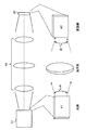
照明効率上の未解決問題としてはエタンデュ、即ちラグランジュ不変量に関するそれがある。光学分野で周知の通り、エタンデュは、その光学系で取り扱うことができる光量に関連している。潜在的には、エタンデュが大きい方が像が明るくなる。数値的には、エタンデュは二種類のファクタの積、即ち像面積と数値開口との積に比例する。図1に示した単純な系、即ち光源12、光学系18及び空間光変調器20からなる系であれば、光源側エタンデュは光源面積A1及び光源出射角幅θ1の積で表される。同様に、空間光変調器20側のエタンデュは変調器面積A2及び変調器入射角幅θ2の積に等しい。輝度を高めるには、光源12の面積を活用してできるだけ多くの光を取り出すのが望ましい。一般には、光源12のエタンデュが空間光変調器20のエタンデュに近い構成が有利である。
An unresolved problem in lighting efficiency is Etendue, that is, Lagrange invariant. As is well known in the optical field, etendue is related to the amount of light that can be handled by the optical system. Potentially, the larger the etendue, the brighter the image. Numerically, the etendue is proportional to the product of two factors, namely the product of the image area and the numerical aperture. In the simple system shown in FIG. 1, that is, a system including the
例えば、数値開口を増すとエタンデュが増して光学系がより多くの光を捕捉できるようになる。同様に、光源面積を増すと光がより広い面積に亘り発生しエタンデュが増すことになる。こうして増大した光源側エタンデュを活用するには、空間光変調器20側のエタンデュを、光源12側のそれ以上にしなければならない。しかしながら、一般に、空間光変調器20を大きくするにはコストがかかる。これが顕著になるのは、LCOS部品、DLP(登録商標)部品等のデバイスを使用した場合である。使用するデバイスのサイズが大きいほど、大きいシリコン基板が必要になり、欠陥の発生数が増すからである。一般に、エタンデュを増すと、より複雑且つ高価な光学系になる。
For example, increasing the numerical aperture increases the etendue and allows the optical system to capture more light. Similarly, when the light source area is increased, light is generated over a wider area and the etendue is increased. In order to utilize the light source side etendue thus increased, the etendue on the
光源側エタンデュが空間変調器側エタンデュと十分に整合しているなら効率は高くなる。エタンデュの整合度合いが低い場合、光学系が光飢渇し空間光変調器に十分な光を供給できない状況か、変調用に生成された光のうちかなりの部分が不効率にも廃棄される状況となる。 If the light source side etendue is well aligned with the spatial modulator side etendue, the efficiency is high. When Etendue's degree of matching is low, the optical system is starved and cannot supply enough light to the spatial light modulator, or a significant part of the light generated for modulation is discarded inefficiently. Become.
固体レーザなら、エタンデュ、寿命、並びにスペクトル的及び輝度的安定性をより優れたものにすることができる。昨今では、VCSEL(垂直共振器面発光レーザ)アレイ等のデバイスが商品化されており、ディジタル映画投射向け光源の候補等として様々な用途が展望されている。しかしながら、それ自体としては輝度が十分高くない。各色投射に十分な輝度を実現するには、例えば9個のアレイを使用しその出射光を互いに結合させる必要がある。 Solid state lasers can provide better etendue, lifetime, and spectral and luminance stability. In recent years, devices such as VCSEL (Vertical Cavity Surface Emitting Laser) arrays have been commercialized, and various uses are expected as light source candidates for digital movie projection. However, the brightness itself is not sufficiently high. In order to achieve sufficient brightness for each color projection, for example, nine arrays must be used and the emitted lights must be coupled to each other.
投射用のレーザアレイとして特に注目を惹いているものとしては、各種VCSELアレイ、例えばVECSEL(垂直拡張共振器面発光レーザ)デバイスや米国カリフォルニア州サニーベール所在のNovaluxが製造しているNECSEL(ノバラックス拡張共振器面発光レーザ)デバイスがある(Novalux(ノバラックス)は登録商標)。 Of particular interest as laser arrays for projection are various VCSEL arrays, such as VECSEL (Vertical Extended Cavity Surface Emitting Laser) devices and NECSEL (Novarax Extension) manufactured by Novalux, Sunnyvale, California, USA (Cavity Surface Emitting Laser) device (Novalux is a registered trademark).
こうしてレーザ技術の改良やフィルタ構成・コストの改良が進んでいるとはいえ、立体投射手法にはまだまだ改良の余地が残っている。例えば、従来手法のうち左目像・右目像間スペクトル分離を使用する手法では、発生した光のうち半分しか個々の目に届かないので、光飢渇が生じやすい。そのため、立体像イメージングシステムにおける光効率向上及び動作・装置コスト低減が求められている。 Although the laser technology and the filter configuration / cost are improved in this way, there is still room for improvement in the stereoscopic projection method. For example, in the conventional method using the spectral separation between the left eye image and the right eye image, only half of the generated light reaches each eye, and thus light starvation is likely to occur. Therefore, there is a demand for improvement in light efficiency and reduction in operation / device cost in a stereoscopic image imaging system.
本発明は、第1目像及び第2目像を有する立体像を表示面上に投射するディジタル立体投射システムであって、
対応する第1スペクトル帯及び第1中心波長を有する第1状態で輻射光を提供する動作並びに対応する第2スペクトル帯及び第2中心波長を有する第2状態で輻射光を提供する動作を交番的に実行するよう制御可能で、第1スペクトル帯と第2スペクトル帯との間に実質的に重複がない1個又は複数個の狭帯域固体可調光輻射器と、
可調輻射器からの光を変調することで変調像を生成する空間光変調器であって、それぞれ一群の可制御な空間光変調器画素を有するものを、1個又は複数個備える画像形成システムと、
可調光輻射器の状態及び空間光変調器画素を同期制御するコントローラであって、可調光輻射器が第1状態にあるとき第1像に係る画像データに従い空間光変調器画素を制御し第1目変調像をもたらす一方、可調光輻射器が第2状態にあるとき第2像に係る画像データに従い空間光変調器画素を制御し第2目変調像をもたらすコントローラと、
第1目変調像及び第2目変調像を表示面に供給する投射光学系と、
を備える。
The present invention is a digital stereoscopic projection system for projecting a stereoscopic image having a first eye image and a second eye image on a display surface,
The operation of providing radiant light in a first state having a corresponding first spectral band and first central wavelength and the operation of providing radiant light in a second state having a corresponding second spectral band and second central wavelength are alternated. One or more narrowband solid-state tunable light radiators that are controllable to perform at substantially no overlap between the first and second spectral bands;
Image forming system comprising one or a plurality of spatial light modulators that generate a modulated image by modulating light from an adjustable radiator, each having a group of controllable spatial light modulator pixels When,
A controller that synchronously controls the state of the adjustable light radiator and the spatial light modulator pixel, and controls the spatial light modulator pixel according to the image data relating to the first image when the adjustable light radiator is in the first state. A controller that provides a first modulated image while providing a second modulated image by controlling the spatial light modulator pixels according to the image data associated with the second image when the adjustable light radiator is in the second state while providing the first modulated image.
A projection optical system for supplying a first modulated image and a second modulated image to the display surface;
Is provided.
本発明によれば、可調光輻射器を使用しているため、所要部品の個数を減らしてシステムコストを抑えることができる。 According to the present invention, since the adjustable light radiator is used, the number of required parts can be reduced and the system cost can be reduced.
本発明によれば、可調光輻射器を使用しているため、対応するスペクトル帯内で輻射光の波長を変化させることによりスペックル(鏡面反射)を低減することができる。 According to the present invention, since the adjustable light radiator is used, speckle (specular reflection) can be reduced by changing the wavelength of the radiated light within the corresponding spectrum band.
本発明は、本願記載の実施形態同士を組み合わせた構成を包含する。「本実施形態」等の表現で参照されている構成は、本発明の実施形態のうち少なくとも1個で使用されうるものである。それとは別に設けた「一実施形態」「諸実施形態」等の表現は、先の構成とは別の構成を示すもの、先の構成と相容れうる別の構成を示すもののいずれでもありうる(明示がある場合や本件技術分野で習熟を積まれた方々(いわゆる当業者)にとり自明な場合を除く)。「手法」「諸手法」等、単複の別を伴う記載は限定を旨とするものではない。ご留意頂きたいことに、明示的に示されている場合や文脈上当然な場合を除き、本願中の語「或いは」「又は」「若しくは」は非排他的な意味合いのものである。 This invention includes the structure which combined embodiment described in this application. A configuration referred to in expressions such as “this embodiment” can be used in at least one of the embodiments of the present invention. Separately, expressions such as “one embodiment” and “various embodiments” may indicate either a configuration different from the previous configuration or a configuration that is compatible with the previous configuration. (Except where there is a clear indication or when it is obvious to those skilled in the technical field (so-called persons skilled in the art)). Descriptions that include one or more of “methods” and “methods” are not intended to be limiting. It should be noted that the words “or”, “or”, “or” in this application have non-exclusive meanings unless explicitly indicated otherwise or contextually.
以下の説明では、本発明に係る装置を構成する部材やそれと密に連携する部材に的を絞っている。ご理解頂けるように、具体的な説明や図示のない諸部材はいわゆる当業者にとり周知の様々な形態をとりうる。 In the following description, the focus is on members constituting the apparatus according to the present invention and members closely associated therewith. As can be understood, members not specifically described or illustrated may take various forms known to those skilled in the art.
別紙図面及び本明細書での説明は、本発明に係る動作の概要を説明するものであり、実際のサイズ乃至スケールを示すためのものではない。本発明に係る部材のうちレーザアレイやその構成部材については、基本構造、形状及び動作原理を明示するため、その寸法を大きめにして描いてある。更に、光学部品を位置決め・実装するための部材等については、本発明の実施に当たり肝要な諸部材に図示・説明を充てるため、その図示・説明を省いてある。 The attached drawings and the description in this specification are intended to explain the outline of the operation according to the present invention, and not to show the actual size or scale. Of the members according to the present invention, the laser array and its constituent members are drawn with larger dimensions in order to clarify the basic structure, shape and operating principle. Further, with respect to members and the like for positioning and mounting the optical component, illustration and explanation are omitted in order to illustrate and explain important members in carrying out the present invention.
使用されている語のうち「第1」「第2」等の語は、部材間の順序や優先度合いを示すものではない。単に、部材相互間の区別をよりはっきりと示すためのものである。 Of the used words, words such as “first” and “second” do not indicate the order or priority between members. It is merely to show the distinction between the members more clearly.
本明細書では、「色」「波長域」「スペクトル帯域」等の語をほぼ同義に使用している。しかし、文脈によって使い分ける場面もある。例えば、レーザ等の固体光源について述べる場合、そのピーク発光波長(635nm等)や発光波長域(630〜640nm等)で表すことよりは、その成分色スペクトル帯域(R(赤)等)で表すことの方が多い。また、本明細書で波長域が「別々」であるという場合、それらの波長域間に実質的に重複がないことを表している。 In this specification, terms such as “color”, “wavelength range”, and “spectral band” are used almost synonymously. However, there are scenes that are used depending on the context. For example, when describing a solid-state light source such as a laser, it is expressed in its component color spectrum band (R (red), etc.) rather than in its peak emission wavelength (635 nm, etc.) or emission wavelength range (630-640 nm, etc.). There are more. In addition, when the wavelength ranges are “separate” in the present specification, it indicates that there is substantially no overlap between the wavelength ranges.
「観衆」「看者」の語は、いずれも、本発明に係る立体像表示を見る人物という意味で使用されている。「左目像」の語は、観衆の左目によって捉えられるように生成される像を指している。同様に、「右目像」の語は、観衆の右目によって捉えられるように生成される像を指している。 The terms “audience” and “viewer” are both used to mean a person who views a stereoscopic image display according to the present invention. The term “left-eye image” refers to an image generated to be captured by the left eye of the audience. Similarly, the term “right eye image” refers to an image generated to be captured by the right eye of the audience.
本発明の諸実施形態では、互いに独立なスペクトル隣接光源群を用い立体像表示システムの輝度を向上させる、という課題に挑んでいる。 Embodiments of the present invention challenge the problem of improving the brightness of a stereoscopic image display system using a group of spectrally adjacent light sources that are independent from each other.
本明細書の文脈上、「透過域」「通過域」の語を互いに等価であるものと捉えている。 In the context of this specification, the terms “transmission zone” and “passage zone” are considered to be equivalent to each other.
本明細書の文脈上、「スペクトル隣接」とは、互いに同一の成分色に該当していてそのスペクトル帯域が近いけれども、スペクトル帯域同士の重複が概ねない、という意味である。成分色とは、カラー像を形成するに当たり使用される諸色、例えばR、G、Bのことであるが、第4の色等々が使用される場合もある。例えば、ある成分色に関しスペクトル隣接色という場合、それらの色が互いに同じ成分色に該当すること、しかし左目像・右目像を弁別できるようそのスペクトル帯域(波長域)の波長的重複が実質的に回避されていること、を表している。 In the context of this specification, “spectrum adjacent” means that the spectral bands correspond to the same component color and the spectral bands are close, but there is almost no overlap between the spectral bands. The component color refers to various colors used for forming a color image, for example, R, G, and B, but a fourth color or the like may be used. For example, in the case of spectral adjacent colors for a certain component color, those colors correspond to the same component color, but the wavelength overlap of the spectral band (wavelength range) is substantially different so that the left eye image and the right eye image can be distinguished. It is being avoided.
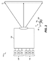
図2に画像生成システムの模式的ブロック構成を示す。この図には、ディジタル立体投射システム110の主要構成要素のうち幾つかが示されている。そのうち一つはプロジェクタ装置120である。プロジェクタ装置120は、スペクトル分離を使用し、左目像及び右目像を、看取スクリーンその他の表示面72上に発生させる。第1の輻射器群(右目光輻射器12R)は、第1赤色スペクトル帯R1、第1緑色スペクトル帯G1及び第1青色スペクトル帯B1にて光を輻射する。輻射された光は、観衆の右目で捉えられる像即ち右目像の生成に使用される。同様に、第2の輻射器群(左目光輻射器12L)は、第2赤色スペクトル帯R2、第2緑色スペクトル帯G2及び第2青色スペクトル帯B2にて光を輻射する。輻射された光は、観衆の左目で捉えられる像即ち左目像の生成に使用される。
FIG. 2 shows a schematic block configuration of the image generation system. In this figure, some of the main components of the digital
本発明を好適に実施する際には、左目光輻射器12Lに係るスペクトル帯それぞれと、右目光輻射器12Rに係るスペクトル帯それぞれが、実質的に重複しないようにする。これは、左目光輻射器12Lによってもたらされる光と、右目光輻射器12Rによってもたらされる光を、フィルタ眼鏡74で効果的に分離できるようにするためである。「実質的に重複しない」とは、一方のスペクトル帯に係る光を無視できない波長のいずれでも、他方のスペクトル帯に係る光のパワー(スペクトルパワー)を無視できる、という意味である。受け容れうる結果が得られる限りスペクトル帯間に若干の重複が残っていてもよい。実施に当たっては、例えば、一方のスペクトル帯に係る光と他方のスペクトル帯に係る光の間の重複量が5%未満、という条件を使用することができる。
When the present invention is suitably implemented, the spectral bands related to the left-eye
フィルタ眼鏡74は、左目フィルタ76L及び右目フィルタ76Rと、それら左目フィルタ76L及び右目フィルタ76Rが実装されるフレーム62とを備えている。フレーム62の役目は、右目フィルタ76Rを看者の右目面前、左目フィルタ76Lを看者の左目面前に配することである。右目フィルタ76Rのスペクトル透過特性は、右目光輻射器12Rに発しスペクトル帯R1,G1,B1に属する光を透過させると共に、左目光輻射器12Lに発しスペクトル帯R2,G2,B2に属する光を阻止する(即ち吸収し又は反射する)よう、設計されている。同様に、左目フィルタ76Lのスペクトル透過特性は、左目光輻射器12Lに発しスペクトル帯R2,G2,B2に属する光を透過させると共に、右目光輻射器12Rに発しスペクトル帯R1,G1,B1に属する光を阻止するよう、設計されている。
The
プロジェクタ装置120は、二通りのプロジェクタデバイスを備える構成にすることができる。例えば、左目光輻射器12L輻射光投射用の左目イメージング路を提供する色チャネルを伴うプロジェクタと、右目光輻射器12R輻射光投射用の右目イメージング路を提供する色チャネルを伴うプロジェクタと、を備える構成である。但し、左目イメージング機能と右目イメージング機能を単一のプロジェクタにまとめることも可能である。それにより、例えば、潜在的な配置特性の長所を顕在化させることや、投射レンズ等の部材に関わるコストを低減することができる。以下の説明では、左目イメージング路及び右目イメージング路を色スクローリングで結合させるタイプのプロジェクタについて詳細な情報を提供する。画像投射分野に係るいわゆる当業者であれば、左目イメージング機能と右目イメージング機能をまとめる手法が他にもあることをご理解頂けよう。本発明の諸実施形態は、スペクトル分離方式を使用する様々な立体投射システムと併用することができる。
The
図3Aに、成分色R、G及びBの光からカラー像を発生させるに当たり従来の非立体像用投射装置で使用されてきた色スクロールシーケンスを模式的に示す。図中の画像フレーム28a、28b、28c、26d及び28eは互いに異なる時点のものである。各フレームの画像領域32は、図示の如く、R色成分に係る帯域光34r、G色成分に係る帯域光34g、並びにB色成分に係る帯域光34bによって、垂直方向に走査されている。画像フレームの下端に達したら上端に戻る、というかたちで各帯域光がスクロールされているので、どの時点をとっても、各色成分が画像フレーム内の1/3ずつを占めている。
FIG. 3A schematically shows a color scroll sequence that has been used in a conventional non-stereoscopic projection apparatus when generating a color image from light of component colors R, G, and B. FIG. The image frames 28a, 28b, 28c, 26d and 28e in the figure are at different times. As shown in the drawing, the
垂直方向にスクロールするのは、水平方向にスクロールすると、看者が横方向に動いたときに色帯域の動きが察知されるからである。この現象を一般にレインボウ効果と呼ぶ。また、本シーケンスで帯域光として使用されるのは、例えば、照明部材からの光で空間光変調器を走査することで得た光、或いは空間光変調器からのイメージング光である。走査動作は、看者に察知されない速度(即ち144Hz等といった高い周波数)で周期的に実行する。本シーケンスから読み取れるように、各画像フレーム28a〜28e内にはそれぞれ三通りの成分色が現れており、互いに別の画像領域がそれによって走査されている。本シーケンスで形成される画像においては、R帯域光34r、G帯域光34g及びB帯域光34bで運ばれるR、G及びBの像コンテンツを使用し個々の画像フレームが形成される。
The reason for scrolling in the vertical direction is that when scrolling in the horizontal direction, the movement of the color band is detected when the viewer moves in the horizontal direction. This phenomenon is generally called the rainbow effect. Moreover, what is used as band light in this sequence is, for example, light obtained by scanning the spatial light modulator with light from the illumination member, or imaging light from the spatial light modulator. The scanning operation is periodically executed at a speed that is not perceived by the viewer (that is, a high frequency such as 144 Hz). As can be read from this sequence, three component colors appear in each of the image frames 28a to 28e, and different image areas are scanned by each. In the image formed by this sequence, individual image frames are formed using R, G, and B image contents carried by the
自明な通り、図3Aに示した色スクロール方式は非立体カラーイメージング用のものであり、立体カラーイメージングシステムに適用するには難がある。この方式で立体カラー像を提供するとなると、各成分色当たり二通り、都合六通りのスペクトル帯域でスクロールする必要があるからである。それぞれその光源なりのエタンデュを有する6個の光源で単一のチップを照明するとなると、クロストーク防止のため個々の光源間に十分なギャップを設ける必要があるし、個々の色に係る色データから他の色に係る色データへと短時間で遷移させるとなると、利用可能なエタンデュが消尽されたり光学的に高速なレンズが必要になったりする。これは実現可能なことではあるが望ましくないことである。なぜなら、プロジェクタの輝度がかなり制限されることとなるし、光学系のコストがひときわ高い構成になるからである。 As is obvious, the color scroll method shown in FIG. 3A is for non-stereoscopic color imaging and is difficult to apply to a stereoscopic color imaging system. This is because if a three-dimensional color image is provided by this method, it is necessary to scroll in six different spectral bands for each component color. When a single chip is illuminated with six light sources each having its own etendue, it is necessary to provide sufficient gaps between the individual light sources to prevent crosstalk, and from the color data relating to the individual colors. When transitioning to color data relating to another color in a short time, the available etendue is exhausted or an optically high-speed lens is required. This is possible but not desirable. This is because the brightness of the projector is considerably limited and the cost of the optical system is extremely high.
画質及び輝度を高めるため、非立体イメージング用映画品質投射システムでは、しばしば、色別のチャネル、一般にはR、G及びBの各色チャネルが設けられる。空間光変調器は各チャネル毎に設けられる。こうした構成では、フィルタ、被覆等といった部材の構成及び形状を最適化しやすく、各波長の光についてその性能を高めやすい。 In order to enhance image quality and brightness, movie quality projection systems for non-stereoscopic imaging often provide color-specific channels, typically R, G and B color channels. A spatial light modulator is provided for each channel. In such a configuration, it is easy to optimize the configuration and shape of members such as filters and coatings, and it is easy to improve the performance of light of each wavelength.
図3Bに、本発明の一実施形態に係る立体投射システム向けの色走査方式を示す。この方式では、異なる色成分に係る帯域によってスクロールされる図2の方式と異なり、単一の成分色スペクトル帯域内でスペクトル隣接しているスペクトル帯域によって、画像領域32がスクロールされている。図示例でスペクトル隣接しているスペクトル帯域36a及び36bはR1及びR2であり、本実施形態ではそれらR1及びR2により画像フレーム38a、38b、38c、38c、38d及び38eがスクロールされる。帯域R1は立体像のうち左目像の投射、帯域R2は右目像の投射に使用される。後に詳述する通り、立体像を構成する各色チャネル毎に、これと同様のスペクトルスクロール機構が使用される。更に、個々の色チャネルにて光が同一色成分に属するので、個々の色成分に係る光学部品用の光学被覆をその色成分向けに最適化させることができる。
FIG. 3B shows a color scanning method for a stereoscopic projection system according to an embodiment of the present invention. In this method, unlike the method of FIG. 2 in which scrolling is performed by bands related to different color components, the
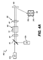
図4A及び図4Bに、本発明の一実施形態に関し単一色チャネル内スペクトル隣接帯域での色スクロールに適した赤色チャネル40rの構成を模式的に示す。まず、光源42aからはスペクトル帯域R1の光ビーム、光源42bからはスペクトル帯域R2の光ビームが発せられる。照明光学系90は概ね均一な帯域光を空間光変調器60に供給し、その変調器60ではスペクトル隣接帯域それぞれに関し変調が実行される。ビーム走査光学系92には、帯域光での周期的スクロールを実行するビーム走査器50が備わっている。ご理解頂けるように、照明光学系90に複数個のレンズ48を設ける場合、そのレンズ48のうち幾つかをユニフォマイジング光学系44・ビーム走査光学系92間、他の幾つかをビーム走査光学系92・空間光変調器60間に配置するとよい。照明光学系90は、例えばそのユニフォマイジング光学系44の出射面を空間光変調器60上にイメージングすることで、均一な帯域光を発生させる。この方式の長所としては、投射中に光源42a及び42bを連続稼働させうるため、他の立体投射方式に比べ出射光量が多い点がある。
4A and 4B schematically show the configuration of the
図4Aに示す構成では、光源42aからの光ビームと光源42bからの光ビームをビーム結合器46で平行光軸上に結合させ、それらスペクトル隣接な光ビームをユニフォマイジング光学系44、例えばレンズレットアレイやユニフォマイジングバーに送ることで、実質的に均一なスペクトル隣接光ビームを発生させるようにしている。ビーム走査器50は、その結合されたスペクトル隣接光ビームを照明光学系90経由で空間光変調器60に差し向け周期的にスクロールさせる。照明光学系90ではそのビームによるイメージングのほかビームの整形及び調整が実行される。この図では照明光学系90がレンズ48として示されているが、これとは別の或いは複数個の光学部品を含む形態で照明光学系90を実現することもできる。帯域光間クロストークを防ぐためのビーム分離は、ビーム走査器50に入射する光ビーム間の空間的乃至角度的分離によって実現できる。角度的分離を実行する場合、他の部品例えばダイクロイックビーム結合器をビーム走査器50の下流に設け、走査されているビームを平行光軸上に戻すようにするのが望ましい。
In the configuration shown in FIG. 4A, a light beam from the
空間光変調器60は、相応の帯域光36a及び36bからなる画像フレーム38を発生させる。帯域光36a及び36bによるスクロールは前述の通り周期的に実行される。空間光変調器60は一群の画素を有しており、画像データに従い個別の画素が変調されることでイメージング光を発生させる。空間光変調器画素のうちスペクトル帯域R1の光で照明されているものは左目像用の画像データ、スペクトル帯域R2の光で照明されているものは右目像用の画像データに従い変調される。
The spatial
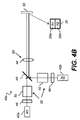
図4Bに示す別の構成では、光源42aから来る光ビーム用と、光源42bから来る光ビーム用とに分け、ユニフォマイジング光学系44及びビーム走査器50が設けられているので、走査された光ビームが2本発生する。ビーム結合器46はそれら走査光ビーム同士を結合させることで結合走査ビームを発生させる。発生した結合光ビームは照明光学系90により空間光変調器60上に送られる。このように複数個のビーム走査器50でビーム走査光学系92を実現してもよい。
In another configuration shown in FIG. 4B, the light beam coming from the
図5に、色チャネルを赤色チャネル40r、緑色チャネル40g及び青色チャネル40bの3個有するディジタル立体投射システム100を模式的に示す。赤色チャネル40rはスペクトル隣接したR色のスペクトル帯域R1及びR2、緑色チャネル40gはスペクトル隣接したG色のスペクトル帯域G1及びG2、青色チャネル40bはスペクトル隣接したB色のスペクトル帯域B1及びB2を扱う。投射光学系70は、3個ある空間光変調器60からのイメージング光を表示面72へと送る。看者は、左目用のフィルタ76Lと右目用のフィルタ76Rを有するフィルタ眼鏡74越しにその表示面72を看取する。フィルタ76Lは、左目像用のイメージング光(スペクトル帯域R1、G1及びB1の光)を選択的に透過させる一方、右目像用のイメージング光(スペクトル帯域R2、G2及びB2の光)を阻止(吸収又は反射)する。同様に、フィルタ76Rは、右目像用のイメージング光(スペクトル帯域R2、G2及びB2の光)を選択的に透過させる一方、左目像用のイメージング光(スペクトル帯域R1、G1及びB1の光)を阻止する。
FIG. 5 schematically shows a digital
コントローラシステム80は、各空間光変調器60を構成する画素を、立体像用画像データに従い同期的に変調させる。コントローラシステム80は、ビーム走査器50との連携を通じ、どの空間光変調器内画素がどのスペクトル隣接帯域の光によってどの時点で照明されるかを察知する。第1スペクトル帯域の光で照明された空間光変調器内画素は左目像用画像データに従い、第2スペクトル帯域の光で照明された空間光変調器内画素は右目像用画像データに従い変調される。第1及び第2スペクトル帯域の光によるスクロールが連続的に行われるので、空間光変調器画素のうちどの部分が左目像用画像データに従い変調されどの部分が右目像用画像データに従い変調されるのかは連続的に切り替わっていく。
The
投射光学系70は、例えば、3個の色チャネルから来る光ビームを(例えばビーム結合光学系を使用し)結合させた後、その結合光ビームを単一の投射レンズ越しに投射する。投射光学系70は、或いは、表示面72上で位置が揃うよう、3個の色チャネルから来る光ビームを色チャネル別の投射レンズ越しに投射する。
For example, the projection
図4A及び図4Bを参照して先に説明した通り、ビーム走査光学系92は1個又は複数個のビーム走査器50を有している。ビーム走査光学系92を用い帯域光スクロールを実行する手法は複数通りある。ビーム走査光学系92は照明用光路上の相応な位置に配置すればよい。図6Aに、本発明の一実施形態に関し、走査素子が1個の素子即ち回転プリズム52であるビーム走査器50を模式的に示す。この構成では、各成分色帯域内のスペクトル隣接帯域毎に回転プリズム52が設けられる。プリズム52を回転させると、屈折により光ビーム(ここではスペクトル帯域R1の光ビーム)の出射位置が変わり、空間光変調器60がそのビームによって周期的にスクロールされることとなる。図6Aの構成は、例えば、図4Bに示した構成の色チャネルで使用される。
As described above with reference to FIGS. 4A and 4B, the beam scanning
図6Aのうち上段の図では、プリズム52が、光ビームがプリズム表面に直交方向から入射するような向きになっている。この場合、光ビームは、その向きを変えずにプリズム52から出射される。中段の図では、プリズム52が軸O回りで回転し、光ビームがプリズム表面に斜め方向から入射するような向きになっている。この場合、光ビームは、下方に屈折し空間光変調器の下部に入射する。下段の図では、プリズム52が更に回転し、光ビームがプリズム52の別の面に入射するような向きになっている。この場合、光ビームは、上方に屈折し空間光変調器の上部に入射する。注記すべきことに、入射してくる光ビームにはある程度の空間的な(並びに角度的な)拡がりがあるので、プリズムの姿勢によっては、入射ビームのうちある部分の光線と他の部分の光線とがプリズム上の別の面に入射することがある。この場合、光線のうち一部は上方、他の一部は下方に転向される。即ち、図3中の画像フレーム38eの如く、帯域光が上下に分かれ、一部がその画像フレーム中の上部、他の一部が下部を組成する状態になる。
In the upper diagram of FIG. 6A, the
図6Bに、ビーム走査器50の別例構成として、ある色チャネルに属するスペクトル隣接帯域(図示例ではR1及びR2)のうち一方に係る帯域光と他方に係る帯域光とが、単一の回転プリズム52により同時走査される構成を模式的に示す。これは図4Aに例示した構成に適する構成である。図示例の場合、スペクトル帯域R1に係る光ビームと、スペクトル帯域R2に係る光ビームとが、プリズム52に入射する。プリズム52が回転すると、両光ビームが屈折により同期的に転向される。
In FIG. 6B, as another example of the configuration of the
図6Cに、ビーム走査器50の更なる別例構成として、ある色チャネルに属するスペクトル隣接帯域(図示例ではR1及びR2)のうち一方に係る帯域光と他方に係る帯域光とが、単一の回転プリズム52により同時走査される構成の別例を模式的に示す。この構成では、回転プリズム52に入射する2本の光ビームが、互いに異なる角度で飛来している。それらスペクトル隣接な光ビームは、それぞれユニフォマイジング光学系44でユニフォマイズされる。この例では、そのユニフォマイジング光学系44にインテグレーティングバー58が備わっている。照明光学系90は、レンズ48を複数個有する第1段94と、同じくレンズ48を複数個有する第2段96とに分かれている。この例では、第1段94内のレンズ48が、インテグレーティングバー58の出射面とプリズム52との間にテレセントリシティが生じるように構成・配置されている。同様に、第2段96内のレンズ48も、プリズム52・空間光変調器60間にテレセントリシティが生じるように構成・配置されている。ダイクロイック結合器82はダイクロイック面84を1個又は複数個有する結合器であり、走査光ビームを平行光軸上に送り出し空間光変調器60を照明するのに使用されている。
In FIG. 6C, as another example of the configuration of the
図6Cに示した多角型の構成は、特許文献6(名称:カラー照明スクロールを伴う投射システム(Projection system with scrolling color illumination),発明者:Conner)記載のものに似ている。特許文献6記載の投射システムは、空間光変調器の諸部分を互いに異なる色帯域で同時に照明するスクロール用プリズムアセンブリを備えている。このシステムでは、白色光を複数通りの色帯域に分割し、スクロール用プリズムを介し別々の方向へと伝搬させる。スクロール色帯域の光は、個々別々の色帯域がスクロール用プリズムアセンブリから互いに平行に出射していくよう、反射によって結合される。但し、特許文献6には、互いに別の光源から来るスペクトル隣接帯域の光でスクロールを行わせ立体像を投射する点に関し教示がない。 The polygonal configuration shown in FIG. 6C is similar to that described in Patent Document 6 (Name: Projection system with scrolling color illumination, Inventor: Conner). The projection system described in Patent Document 6 includes a scroll prism assembly that simultaneously illuminates portions of the spatial light modulator in different color bands. In this system, white light is divided into a plurality of color bands and propagated in different directions via a scroll prism. The light in the scroll color band is coupled by reflection so that the individual color bands exit parallel to each other from the scroll prism assembly. However, Patent Document 6 does not teach that a stereoscopic image is projected by scrolling with light in adjacent spectral bands coming from different light sources.
回転プリズム等の屈折素子は、ビーム走査器50として好適に使用できる部材の一種である。本願では、「プリズム」「プリズム素子」等の語を、光学系での常識に従い、概ねその光入射面が平坦なn面多角柱状光学素子のうち光屈折性のある透明固体素材で形成されている透明素子、なる意味で使用している。ご理解頂けるように、形状及び表面輪郭に関しいう限り、光学的な意味でのプリズムの範囲は幾何学的定義によるそれよりも広く、より広範な範囲を包含している。図6A〜図6Cにはその断面が正方形の正方プリズムを示したが、切り子面の個数を4個超にした方が走査結果がよくなる場合も多い。例えば、六角プリズムや八角プリズムを用いた実施も可能である。
A refractive element such as a rotating prism is a kind of member that can be suitably used as the
ビーム走査器50として使用できるその他の部材としては、回転ミラーその他の反射性部材、ビーム光路を並進させて可変光屈折を起こす部材、反復運動部材例えばガルバノメータ駆動ミラー、枢動型のプリズム、ミラー乃至レンズ等がある。
Other members that can be used as the
ビーム走査器50を複数個使用する場合、全ビーム走査器50の回転を同期させること、ひいては各スペクトル帯域に係る画像データ同士を同期させることが重要となる。図示しないが、その手法の一つとしては、互いに別のビーム走査器50に係る運動光学部品が共通のモータで制御されるよう光学的な構成を工夫する、という手法がある。例えば、単一の軸及び単一のモータで複数個のプリズム52を駆動する構成にすればよい。また、単一の回転プリズム52を用い複数通りのスペクトル帯域を走査する場合、複数通りの方向から来る光ビームをそのプリズム52で転向させる構成や、そのプリズム52上の互いに異なる部分で光ビームを転向させる構成(図6B参照)にすればよい。
When a plurality of
図4A、図4B及び図5に例示した通り、ビーム光路をスペクトル隣接帯域間で互いに平行にするには、ビーム結合器46を用い空間光変調器60を照明するようにすればよい。そのビーム結合器46としては、ダイクロイックビーム結合器等、本件技術分野で既知の各種ビーム結合光学系を使用することができる。
As illustrated in FIG. 4A, FIG. 4B, and FIG. 5, in order to make the beam optical paths parallel to each other between adjacent spectral bands, the
ユニフォマイジング光学系44には、光源42a及び42bから来る光ビームを調整し、実質的に均一な走査用光ビームを発生させる働きがある。本願では、この表現「実質的に均一」を、空間光変調器60に入射する光ビームの強度が十分に一定であり、看者がその違いを視認できない、という意味で使用している。実際には、ユニフォマイズされた光ビームの強度が約30%の精度で一定であればよい。そうすれば、発生する変動の大部分が、ユニフォマイズされたビームのエッジに向かい低レベルになる。ユニフォマイジング光学系44としては、本件技術分野で既知の諸構成、例えばインテグレーティングバーやレンズレットアレイを使用することができる。
The uniformizing
図7Aに、図4Aに示した構成で使用可能なユニフォマイジング光学系44の一例を示す。このユニフォマイジング光学系44では、光ビームをユニフォマイズするのに一対のレンズレットアレイ54が使用されている。空間的に隣接する光ビームのうち1本(例えばスペクトル帯域R1に係る方)はレンズレットアレイ54の上半分を通り、もう1本(例えばスペクトル帯域R2に係る方)は同じレンズレットアレイ54の下半分を通る。56は不透明なブロックであり、スペクトル隣接帯域間で光ビームを遮りクロストークを防ぐのに使用されている。こうした構成であれば、一色当たり1個のレンズレットアレイ構造でよいのでコストを抑えることができる。
FIG. 7A shows an example of a uniformizing
図7Bに、図4Aに示した構成で使用可能なユニフォマイジング光学系44の別例を示す。このユニフォマイジング光学系44では、光ビームをユニフォマイズするのに一対のインテグレーティングバー58が使用されている。空間的に隣接する光ビームのうち1本(例えばスペクトル帯域R1に係る方)は上側のインテグレーティングバー58を通り、もう1本(例えばスペクトル帯域R2に係る方)は下側のインテグレーティングバー58を通る。
FIG. 7B shows another example of the uniformizing
先に述べた通り、実施に当たっては、イメージング光をビーム走査光学系92に通しつつ、ユニフォマイジング光学系44の出射面を空間光変調器60上に照明光学系90でイメージングする構成にするのが望ましい。いわゆる当業者には自明な通り、こうした機能は、様々な構成の照明光学系90で実現することができる。図8に、照明光学系90が第1段94と第2段96に分かれていて、各段がレンズ48を2個ずつ有する構成を示す。第1段94内のレンズ48は、インテグレーティングバー58の出射面の像を中間像面98上、即ちビーム走査器50の一構成部材たるプリズム52の位置に発生させる。第2段96は、その中間像面98の像を空間光変調器60上に発生させることで、実質的に均一な帯域光36a及び36bをもたらす。空間光変調器は、プリズム52の回転に伴いそれら帯域光によって走査される。レンズ48を適宜用いれば、中間像の倍率をプリズム52のサイズに従い調整することや、走査帯域光の倍率を空間光変調器60のサイズに従い調整することができる。
As described above, in implementation, the imaging light is passed through the beam scanning
コントローラシステム80(図5参照)は、各空間光変調器60を構成する画素群を、立体像用画像データに従い同期的に変調させる。コントローラシステム80内論理回路は、各光帯域36a及び36bの位置に相応するよう、左目像コンテンツに係る画像データ及び右目像コンテンツに係る画像データを供給する。コントローラシステム80としては、例えばコンピュータやプロジェクタシステム専用のプロセッサ乃至マイクロプロセッサを使用することができる。ハードウェア内に組み込んでもよい。
The controller system 80 (see FIG. 5) synchronously modulates the pixel group constituting each spatial
本発明を実施するに当たっては、レーザ、発光ダイオード(LED)等の固体光源をはじめ、そのスペクトル帯域の半値全幅(FWHM)が15nm以下の狭帯域光源、特にそのスペクトル帯域幅が10nm以下の狭帯域光源を使用するのが望ましい。他種光源、例えば量子ドット光源や有機発光ダイオード(OLED)光源も使用することができる。更に、その色チャネル向けのスペクトルコンテンツを通すフィルタを1個又は複数個の白色光源に付加したものも使用することができる。多色光乃至白色光を諸色の光に分解する手法は、画像投射分野ではいわゆる当業者にとり周知である。そうした手法は、例えば、X−cube(登録商標)、フィリップス(登録商標)プリズム等といった標準的なデバイスを相応の光調整・供給手法と組み合わせる形態にて実行することができる。 In carrying out the present invention, a solid-state light source such as a laser or a light emitting diode (LED), a narrow-band light source having a full width at half maximum (FWHM) of 15 nm or less, particularly a narrow-band having a spectral bandwidth of 10 nm or less. It is desirable to use a light source. Other light sources such as quantum dot light sources and organic light emitting diode (OLED) light sources can also be used. Furthermore, it is also possible to use a filter in which one or a plurality of white light sources are added with a filter that passes spectral content for the color channel. A technique for decomposing multicolor light or white light into light of various colors is well known to those skilled in the art in the field of image projection. Such a technique can be executed in a form in which a standard device such as an X-cube (registered trademark), a Philips (registered trademark) prism or the like is combined with a corresponding light adjustment / supply method.
レーザを使用する大きな利点としては、スペクトル隣接スペクトル帯の帯域幅を抑制でき、隣接帯域間の分離度を増して色域を拡げられる点がある。これは、個々の目のフィルタが不可避的に角度に敏感で、非直交方向からの入射によりフィルタエッジ遷移の波長がシフトするので、有益なことである。この角度敏感性は光フィルタ設計の分野で広く知られている問題である。従って、狭帯域輻射を使用することは、この問題を解決し、多量のクロストークを発生させることなく共通のシフトを発生させるのに役立つ。多くのレーザでは帯域幅が1nmオーダである。これは理想的かに見えるが、他の要素、例えばスペックル低減のようにスペクトル帯が広い方がよい要素もある。(スペックルは、光学部品の欠陥によるコヒーレント光の干渉によって生じる。)スペックルはどのような種類の光源でも生じるが、LED更にはレーザのような狭帯域光源で最も顕著になる。好適なスペクトル分離を提供すること及びスペックル感度を低下させることを折衷させるとしたら、好ましい帯域幅は5〜10nmの範囲内である。15〜20nmのスペクトル分離が実現できれば、フィルタの角度感度問題を緩和するのに一般には十分である。 The great advantage of using a laser is that the bandwidth of spectral adjacent spectral bands can be suppressed, and the color gamut can be expanded by increasing the degree of separation between adjacent bands. This is beneficial because the filters of the individual eyes are inevitably sensitive to angles, and the wavelength of the filter edge transitions shift with incidence from non-orthogonal directions. This angular sensitivity is a well-known problem in the field of optical filter design. Therefore, using narrowband radiation helps to solve this problem and generate a common shift without generating a lot of crosstalk. Many lasers have bandwidths on the order of 1 nm. While this appears to be ideal, there are other factors, such as speckle reduction, where a wider spectral band is better. (Speckle is caused by coherent light interference due to defects in optical components.) Speckle occurs with any type of light source, but is most pronounced with narrowband light sources such as LEDs and lasers. The preferred bandwidth is in the range of 5-10 nm, given the compromise of providing suitable spectral separation and reducing speckle sensitivity. Achieving 15-20 nm spectral separation is generally sufficient to alleviate the angular sensitivity problem of the filter.
図9に、投射光学系70に関し共通光路を使用するディジタル立体投射システム100を模式的に示す。このディジタル立体投射システムには、赤色チャネル40r、緑色チャネル40g及び青色チャネル40bが備わっている。各色チャネルには、スペクトル隣接帯域の対毎に1個又は複数個の光源アレイ(例えばレーザアレイ光源)が備わっている。スペクトル隣接帯域のうち左目用のスペクトル帯(R2,G2,B2)に係る光ビームは光源42a、右目用のスペクトル帯(R1,G1,B1)に係る光ビームは光源42bで発生させる。各色チャネルには、光源42a及び42bからの光ビームを共通の方向へと転向させる光転向プリズム30が設けられており、左目及び右目スペクトル帯(例えばスペクトル帯域R1及びR2)の空間隣接光ビームからなる結合光ビームを発生させるのに使用されている。スペクトル隣接帯域のうち右目スペクトル帯(例えばR1)に由来する光ビームはその結合光ビームの一方の側に、左目スペクトル帯(例えばR2)に由来する光ビームは他方の側に集まっている。こうした使途に使用できる光転向プリズム30としては、例えば、前掲の特許文献3(名称:独立多波長光源を用いたプロジェクタ(Projector using independent multiple wavelength light sources),発明者:Silverstein,譲受人:本願出願人,審査に係属中)に記載のものがある。
FIG. 9 schematically shows a digital
各成分色チャネルの結合光ビームは、対応するユニフォマイジング光学系44、ビーム走査光学系92及び照明光学系90を通り更にダイクロイック面68で反射される。これにより、対応する空間光変調器60上に、走査第1帯域光36a及び走査第2帯域光36bがもたらされる。コントローラシステム80(図5参照)は、その空間光変調器内の画素群を立体像用画像データに従い同期的に変調させる。即ち、空間光変調器画素のうち第1帯域光(例えばR1内の光)で照明されるものを左目像用画像データ、第2帯域光(例えばR2内の光)で照明されるものを右目像用画像データに従い変調させる。
The combined light beam of each component color channel passes through the corresponding uniformizing
空間光変調器60にて生じる変調イメージング光ビームは、ダイクロイック面68を透過した後、ダイクロイック面84複数個を有するダイクロイック結合器82の働きで共通光軸上に結合される。その結合光ビームは、投射光学系70によって図示しない表示面上に投射され、装着しているフィルタ眼鏡74(図5参照)を介し看者によって看取される。
The modulated imaging light beam generated by the spatial
図9に示した構成では、赤色、緑色及び青色の各成分色チャネル当たり1個、都合3個の空間光変調器60が使用されている。各空間光変調器60は、対応する成分色チャネルにて使用したスペクトル隣接帯域に係るスクロール帯域光によって照明される。こうした空間光変調器は、そのディジタル立体投射システム100内でも高価格且つ複雑な構成部材の一つとなりがちである。
In the configuration shown in FIG. 9, three spatial
図10に、別例に係るディジタル立体投射システム110、特に左目像形成システム41Lに係る空間光変調器60Lと右目像形成システム41Rに係る空間光変調器60Rを併せ空間光変調器が2個だけの構成を模式的に示す。左目像形成システム41Lには、各成分色スペクトル(R1、G1及びB1)毎に1個ずつ、都合3個の左目光源43Lが備わっている。同様に、右目像形成システム41Rには、各成分色スペクトル(R2、G2及びB2)毎に1個ずつ、都合3個の右目光源43Rが備わっている。各右目光源43Rは、対応する左目光源43Lに対しスペクトル隣接である。
FIG. 10 shows a digital
左目像及び右目像形成システムは、それぞれ、ユニフォマイジング光学系44、ビーム走査光学系92、照明光学系90及びダイクロイック面68を備えており、ダイクロイック面68の働きで走査光ビームが空間光変調器60L及び60R上に送られる構成となっている。この構成では、左目像形成システム41Lが、それぞれR、G及びBスペクトル帯域(R1、G1及びB1)に対応する都合3通りの走査帯域光34r、34g及び34bを発生させる。同様に、右目像形成システム41Rは、それぞれR、G及びBスペクトル帯域(R2、G2及びB2)に対応する都合3通りの走査帯域光35r、35g及び35bを発生させる。
The left-eye image formation system and the right-eye image formation system each include a uniformizing
コントローラシステム(図示せず)は、左目像形成システム41L内空間光変調器60Lを構成する画素群を、左目像用画像データに従い同期的に変調させる。その際、各帯域光(R1、G1及びB1)によって照明される画素群は、左目像用画像データのうち、対応する色チャネルに係る画像データに従い変調される。同様に、コントローラシステムは、右目像形成システム41R内空間光変調器60Rを構成する画素群を、右目像用画像データに従い同期的に変調させる。その際、各帯域光(R2、G2及びB2)によって照明される画素群は、右目像用画像データのうち、対応する色チャネルに係る画像データに従い変調される。
The controller system (not shown) synchronously modulates the pixel group constituting the spatial
ダイクロイック結合器82に備わるダイクロイック面84は、左目像形成システム41Lからのイメージング光並びに右目像形成システム41Rからのイメージング光を共通光軸上に結合させる。投射光学系70はその軸上のイメージング光を表示面上に投射する。ダイクロイック面84としては、相応のノッチ群を有するスペクトルコームフィルタを使用するのが望ましい。即ち、右目光源43R由来のイメージング光に相応するスペクトル帯域(R2、G2及びB2)の光を透過させる一方、左目光源43L由来のイメージング光に相応するスペクトル帯域(R1、G1及びB1)の光を反射する、という特性のものを使用するのが望ましい。スペクトルコームフィルタは、本件技術分野で既知の諸手法、例えば多層薄膜ダイクロイックフィルタ被覆法や相互押し出しストレッチポリマ膜構造形成法で形成することができる。ダイクロイック面84として使用可能なスペクトルコームフィルタをもたらすダイクロイックフィルタ形成手法としては、更にルゲートフィルタ法がある。ルゲートフィルタは一種の干渉フィルタであり、深くて狭い阻止域を呈する一方、それ以外のスペクトルでは高くて平坦な通過域を呈する。ルゲートフィルタの製造には、光学膜層内に亘り屈折率を連続的に変化させる製造プロセスが使用される。ルゲートフィルタには、その屈折率が異なる物質による層を幾つか設ける標準的なノッチフィルタに比べ、リプルが少なく高調波反射が生じないという特徴がある。
The
表1及び表2に、本発明の諸実施形態に係るスペクトル隣接スペクトル帯の例を示す。

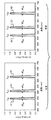
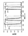
図11Aに、表1に記した例に関し各成分色に係る右目用スペクトル帯R1,G1,B1及び左目用スペクトル帯R2,G2,B2の配置を示す。各スペクトル帯の中心波長はλR1,λG1,λB1,λR2,λG2,λB2、帯域幅はWR1,WG1,WB1,WR2,WG2,WB2である。図11Aの配置では、スペクトル帯がその中心波長に従い交互配置されている(λB1<λB2<λG1<λG2<λR1<λR2)。 FIG. 11A shows the arrangement of the right-eye spectral bands R1, G1, and B1 and the left-eye spectral bands R2, G2, and B2 related to the component colors in the example shown in Table 1. The center wavelengths of each spectrum band are λ R1 , λ G1 , λ B1 , λ R2 , λ G2 , λ B2 , and the bandwidths are W R1 , W G1 , W B1 , W R2 , W G2 , W B2 . In the arrangement of FIG. 11A, the spectrum bands are alternately arranged according to the center wavelength (λ B1 <λ B2 <λ G1 <λ G2 <λ R1 <λ R2 ).
帯域幅は、スペクトル帯毎に相応の幅指標を用い表現することができる。一般に、帯域幅は、そのスペクトル帯の下側エッジ(カットオンエッジ)と上側エッジ(カットオフエッジ)の波長差として定義される。例えば、半値全幅帯域幅の場合、そのスペクトル帯におけるスペクトルパワーがピーク値の半分に低下する波長を以て下側エッジ及び上側エッジとする。また、これとは別の条件に従い下側エッジ及び上側エッジを定義することもできる。例えば、ピーク値の半分ではなく10%パワーレベルや25%パワーレベルといったレベルにスペクトルパワーが低下する波長を以てエッジとしてもよい。また、帯域幅を、別のスペクトル帯幅指標(例えばそのスペクトル帯でのスペクトルパワー分布における標準偏差の複数倍)に従い表現することもできる。 The bandwidth can be expressed using a corresponding width index for each spectrum band. In general, the bandwidth is defined as the wavelength difference between the lower edge (cut-on edge) and the upper edge (cut-off edge) of the spectrum band. For example, in the case of the full width at half maximum bandwidth, the lower edge and the upper edge are determined by the wavelength at which the spectrum power in the spectrum band drops to half of the peak value. Further, the lower edge and the upper edge can be defined according to different conditions. For example, instead of half the peak value, the edge may be an edge with a wavelength at which the spectral power drops to a level such as 10% power level or 25% power level. The bandwidth can also be expressed according to another spectral bandwidth index (for example, a multiple of the standard deviation in the spectral power distribution in that spectral band).
図11Aに示した例では、各スペクトル帯の帯域幅が約10〜15nm、隣接スペクトル帯間波長差が15nm以上となっている。これとは別の帯域幅又は隣接スペクトル帯間波長差を呈する光輻射器を使用し実施してもよい。ディジタル投射システムで使用される一般的な光輻射器の最小帯域幅は、単体レーザの帯域幅に対応する約1nmである。 In the example shown in FIG. 11A, the bandwidth of each spectral band is about 10 to 15 nm, and the wavelength difference between adjacent spectral bands is 15 nm or more. An optical radiator that exhibits a different bandwidth or a wavelength difference between adjacent spectral bands may be used. The minimum bandwidth of a typical light radiator used in a digital projection system is about 1 nm, corresponding to the bandwidth of a single laser.
スペクトル帯の中心波長は、そのスペクトル帯の中心傾向に係る様々な指標を用いて表現することができる。例えば、そのスペクトル帯のピーク波長、重心(セントロイド)波長、下側エッジ・上側エッジ間平均波長等を以て、中心波長とすることができる。 The center wavelength of a spectrum band can be expressed using various indexes related to the center tendency of the spectrum band. For example, the center wavelength can be determined by the peak wavelength, the centroid wavelength, the average wavelength between the lower edge and the upper edge, and the like of the spectrum band.
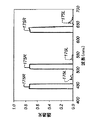
図11Bに、表2に記した例に関し各成分色に係る右目用スペクトル帯R1,G1,B1及び左目用スペクトル帯R2,G2,B2の配置を示す。この例では、それらのスペクトル帯が、各スペクトル帯の中心波長に従い非交互配置されている(λB1<λB2<λG2<λG1<λR1<λR2)。スペクトル帯G1及びG2の配置を、図11Aに示した順ではなく図11Bに示した順にすることは、後に詳述する通り、フィルタガラス被覆の設計を単純化すること等が可能になるため一般に有益である。 FIG. 11B shows the arrangement of the right-eye spectral bands R1, G1, B1 and the left-eye spectral bands R2, G2, B2 relating to the component colors in the example shown in Table 2. In this example, these spectrum bands are non-alternately arranged according to the center wavelength of each spectrum band (λ B1 <λ B2 <λ G2 <λ G1 <λ R1 <λ R2 ). Generally, the arrangement of the spectral bands G1 and G2 in the order shown in FIG. 11B instead of the order shown in FIG. 11A can simplify the design of the filter glass coating, as will be described in detail later. It is beneficial.
注記すべきことに、使用するRGB基本色に違いがあるため、右目イメージング路・左目イメージング路間には、一般に、僅かな色域差が生じうる。従って、右目イメージング路で使用される基本色に係るスペクトル帯と、左目イメージング路で使用される基本色に係るスペクトル帯とに対処するには、白バランス、色補正変換等の色処理を別々に分けることが一般的に必要となろう。白バランスは、例えば、1個又は複数個の輻射器における輝度を調整すること、各色チャネルに変換を適用すること、照明タイミングを調整すること、色強度調整用フィルタを適用すること等により実行することができる。色補正変換は、一群の入力色値に係る色発現が所望のそれになるよう、各色チャネルの制御信号を決定するのに使用される。色補正変換は、一般に、ある種の色域マッピングをも包含する。左目イメージング路及び右目イメージング路で使用される基本色に係る色域外に入力色値がある場合に関し、適当な出力色を決定するためである。色補正動作は、色変換行列を適用すること、或いは三次元ルックアップテーブル(3D LUT)等の色変換手段を適用することにより実行することができる。各組基本色向けにふさわしい色変換を決定する方法は本件技術分野で周知である。 It should be noted that there is a difference in RGB basic colors to be used, so that a slight color gamut difference may generally occur between the right eye imaging path and the left eye imaging path. Therefore, in order to deal with the spectrum band related to the basic color used in the right-eye imaging path and the spectrum band related to the basic color used in the left-eye imaging path, color processing such as white balance and color correction conversion is performed separately. It will generally be necessary to divide. The white balance is executed by, for example, adjusting the luminance in one or a plurality of radiators, applying conversion to each color channel, adjusting the illumination timing, applying a color intensity adjustment filter, or the like. be able to. The color correction transformation is used to determine the control signal for each color channel so that the color expression associated with the group of input color values is as desired. Color correction transformations generally also include some kind of gamut mapping. This is to determine an appropriate output color when the input color value is outside the color gamut related to the basic color used in the left-eye imaging path and the right-eye imaging path. The color correction operation can be performed by applying a color conversion matrix or applying color conversion means such as a three-dimensional lookup table (3D LUT). Methods for determining the appropriate color transformation for each set of basic colors are well known in the art.
波長ベース立体イメージングシステムでは、更なるスペクトル帯を使用することも可能である。従って、非立体イメージングアプリケーションについてシステムを使用する場合、更なる色域を使用することができる。この目的で使用できる技術の例としては、特許文献7(名称:狭帯域輻射器付2D/3Dスイッチャブルカラー表示装置(2D/3D Switchable Color Display Apparatus with Narrow Band Emitters),発明者:Ellinger et al.,譲受人:本願出願人)に記載のものがある。 It is also possible to use additional spectral bands in wavelength-based stereoscopic imaging systems. Thus, additional color gamuts can be used when using the system for non-stereoscopic imaging applications. Examples of techniques that can be used for this purpose include Patent Document 7 (name: 2D / 3D Switchable Color Display Apparatus with Narrow Band Emitters), Inventor: Ellinger et al. , Assignee: Applicant).
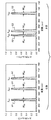
フィルタ眼鏡74(図5)に備わる右目フィルタ76R及び左目フィルタ76Lは、それぞれ、右目像及び左目像のうち対応する像に係るスペクトル帯を通過させるが別の像に係るスペクトル帯は阻止する、というスペクトル透過特性を呈するように設計される。図12Aに、右目フィルタ76Rの透過率(右目フィルタ透過率78R)及び左目フィルタ76Lの透過率(左目フィルタ透過率78L)の例を示す。この例は、図11Aに示した交互スペクトル帯配置で使用されうるものである。右目フィルタ透過率78Rは、右目用スペクトル帯R1,G1,B1に属する光の大半を透過させる一方、左目用スペクトル帯R2,G2,B2に属する光の大半を阻止するように設計されている。同様に、左目フィルタ透過率78Lは、左目用スペクトル帯R2,G2,B2に属する光の大半を透過させる一方、右目用スペクトル帯R1,G1,B1に属する光の大半を阻止するように設計されている。この例では、右目フィルタ透過率78R及び左目フィルタ透過率78Lの特性が共にコームフィルタ特性であり、それぞれ2個のコンティギュアスな帯域通過フィルタ透過帯77B及び1個のコンティギュアスなエッジフィルタ透過帯77Eを有している。透過帯がコンティギュアスであると認められるのは、その透過帯内の全波長に亘り少なくともある最低透過率(例.50%)を呈する場合である。
The
画像輝度に大きな損失が生じないようにするため、右目フィルタ76R及び左目フィルタ76Lは、原則として、対応する目のスペクトル帯に属する光のうち少なくとも50%が透過するように設計される。好ましくは、80%以上を透過させるように設計する。問題となるクロストークが発生しないようにするため、右目フィルタ76R及び左目フィルタ76Lは、原則として、別の目のスペクトル帯に属する光のうち5%未満しか透過させないように設計される。好ましくは、クロストークが実質的に知覚不能となるよう、2%未満しか透過させない設計とする。
In order to prevent a large loss in image luminance, the
図12Bに、右目フィルタ76Rの透過率(右目フィルタ透過率79R)及び左目フィルタ76Lの透過率(左目フィルタ透過率79L)の別例を示す。この例は、図11Bに示した非交互スペクトル帯配置で使用されうるものである。図12Bに示した特性は、図12Aに示した特性に比べ、エッジ遷移の個数が少ない点で有利である。具体的には、右目フィルタ透過率78R及び左目フィルタ透過率78Lが、いずれも、1個の帯域通過フィルタ透過帯77B及び1個のエッジフィルタ透過帯77Eしか有していない。これが可能になるのは、スペクトル帯の順序を変えたためである。即ち、右目緑色スペクトル帯G1・右目赤色スペクトル帯R1間に左目スペクトル帯が介在しておらず、また左目青色スペクトル帯B2・左目緑色スペクトル帯G2間に右目スペクトル帯が介在していないからである。そのため、各フィルタにおける低透過率から高透過率へ又は高透過率から低透過率へのエッジ遷移の個数が、図12Aに示した配置では5個であるのに対し、図12Bに示した配置では3個しか必要でなくなっている。一般に、フィルタ設計の難度は、エッジ遷移の個数が多いほど高く、また鋭いエッジ遷移が求められるほど高い。その点、帯域通過フィルタ透過帯の個数が少なければエッジ遷移の個数が少なくなるので、そうしたフィルタは顕著に容易に、またより少数のフィルタ層で安価に製造することができる。これは重要な長所である。なぜなら、投射された立体像を鑑賞する観衆一人一人が使用するものであるため、フィルタ眼鏡74は大量に製造する必要があるからである。図12Bに示した配置の更なる長所としては、逆の目のスペクトル帯が透過帯に漏れ出うるエッジ遷移の個数が少ないため、クロストークが発生する機会が少ない、という点がある。
FIG. 12B shows another example of the transmittance of the
フィルタ眼鏡74(図5)に備わる右目フィルタ76R及び左目フィルタ76Lは、本件技術分野で既知の手法により製造することができる。例えば、左目フィルタ76L、右目フィルタ76R又はその双方を、多層薄膜被覆を有する光学面を備えたダイクロイックフィルタとすることができる。多層薄膜被覆は相応のフィルタ透過率、例えば図12A中の右目フィルタ透過率78R及び左目フィルタ透過率78Lや図12B中の右目フィルタ透過率79R及び左目フィルタ透過率79Lをもたらすように設計することができる。スペクトル透過特性が所望の特性になるよう多層薄膜被覆を設計・製造する手法は、本件技術分野で広く知られている。
The
また、左目フィルタ76L、右目フィルタ76R又はその双方を、共押し出しストレッチポリマ膜構造を用い形成される多層ダイクロイックフィルタにすることもできる。そうした構造を生成する方法としては、例えば特許文献8(名称:先鋭化バンデージ光学膜(Optical film with sharpened bandedge),発明者:Wheatley et al.)に記載のものがある。この方法では、熱プラスティファイングエクストルーダ等のソースからコエクストルージョン装置へと、多様な熱可塑性ポリマ素材の流れが供給される。エクストルーダは、それらポリマ素材からなる多層構造を押し出し成形する。機械操作部を使用しその多層構造をストレッチすることで、所望の光学厚にすることができる。
Alternatively, the left-
クロストークは、立体イメージングシステムで発生することがある望ましくない偽像、即ち看者の左目(右目)向けに生成された画像コンテンツが右目(左目)向け画像コンテンツに入り込むことで生じる偽像である。これは、主たる画像から空間的にずれた位置を占める微かな物体像(ゴースト像)として看者に知覚されてしまうことがある。問題を孕むクロストークを防ぐには、右目フィルタ76Rを透過する光のうち左目光輻射器12Lに発する光の量を、右目フィルタ76Rを透過する光のうち右目光輻射器12Rに発する光の量に対して、僅かな比率に抑えることが重要である。同様に、左目フィルタ76Lを透過する光のうち右目光輻射器12Rに発する光の量を、左目フィルタ76Lを透過する光のうち左目光輻射器12Lに発する光の量に対して、僅かな比率に抑えることも重要である。
Crosstalk is an undesirable artifact that can occur in a stereoscopic imaging system, that is, an artifact generated when image content generated for the viewer's left eye (right eye) enters the image content for the right eye (left eye). . This may be perceived by the viewer as a faint object image (ghost image) occupying a position spatially deviated from the main image. To prevent problematic crosstalk, the amount of light transmitted through the
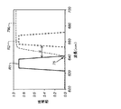
図13に、波長ベース立体イメージングシステムにおけるクロストークの発生源を示す。この図では、右目赤色スペクトル帯R1及び左目赤色スペクトル帯R2を含む波長域がクローズアップされている。図中の左目フィルタ透過率79Lは、左目赤色スペクトル帯R2に属する光の大半を透過させる一方、右目赤色スペクトル帯R1に属する光の大半を阻止する特性となっている。しかしながら、図示の通り僅かな重複領域75がある。この領域では、右目赤色スペクトル帯R1に属する光の少量が、左目フィルタ透過率79Lの特性によって透過されてしまう。透過された右目光が看者の左目に届くとクロストークが発生し、微かなゴースト像が現れてしまう。
FIG. 13 shows a source of crosstalk in the wavelength-based stereoscopic imaging system. In this figure, the wavelength region including the right-eye red spectral band R1 and the left-eye red spectral band R2 is shown in close-up. The left-
クロストークの量は様々な指標によって表現することができる。そうした指標のうち一つは、次の式
ディジタル立体投射システム110(図2)で発生するクロストークの量は、様々なファクタにより影響される。例えば、左目用スペクトル帯・右目用スペクトル帯間波長分離量、光輻射器スペクトル帯に係るエッジ遷移の鋭さ、フィルタ透過帯に係るエッジ遷移の鋭さ、光輻射器スペクトル帯・フィルタ透過帯間整列具合等のファクタである。フィルタ透過帯に係るエッジ遷移の場所が往々にして入射角の関数となるので(例.ダイクロイックフィルタの場合)、クロストークの量は看取角の関数になり得る。 The amount of crosstalk that occurs in the digital stereo projection system 110 (FIG. 2) is affected by various factors. For example, left-eye spectral band / right-eye spectral band separation, edge transition sharpness associated with optical radiator spectral band, edge transition sharpness associated with filter transmission band, alignment between optical radiator spectral band and filter transmission band Etc. Since the location of the edge transition associated with the filter transmission band is often a function of the incident angle (eg, in the case of a dichroic filter), the amount of crosstalk can be a function of the viewing angle.
左目用スペクトル帯・右目用スペクトル帯間波長差はひときわ重要なファクタであるので、クロストークが生じないようディジタル投射システムを設計する際に必ず考慮しなければならない。この波長差は、下側スペクトル帯の上側エッジ(カットオフエッジ)から上側スペクトル帯の下側エッジ(カットオンエッジ)までの波長間隔として定義することができる。この波長間隔は、各帯域エッジ上の半値点に基づき計測、導出することができる。例えば、図13中のSは、右目赤色スペクトル帯R1・左目赤色スペクトル帯R2間波長差を表している。問題となるクロストークを避けるのに必要な波長差の量は、フィルタ透過率に現れるエッジ遷移の鋭さや、入射角によるエッジ遷移位置の変化等の諸効果に影響される。 Since the wavelength difference between the left-eye spectrum band and the right-eye spectrum band is an extremely important factor, it must be considered when designing a digital projection system so that crosstalk does not occur. This wavelength difference can be defined as the wavelength interval from the upper edge (cut-off edge) of the lower spectral band to the lower edge (cut-on edge) of the upper spectral band. This wavelength interval can be measured and derived based on the half-value point on each band edge. For example, S in FIG. 13 represents the wavelength difference between the right-eye red spectral band R1 and the left-eye red spectral band R2. The amount of wavelength difference necessary to avoid crosstalk that is a problem is affected by various effects such as the sharpness of edge transitions appearing in the filter transmittance and the change in edge transition position due to the incident angle.
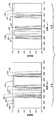
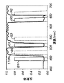
図14に、波長ベース立体イメージングシステム向けに使用される市販フィルタ群に関し、入射角によるエッジ遷移位置の変化を示す。グラフ130に示したのは、右目フィルタにおけるスペクトル透過率曲線の計測結果、特に垂直入射光によるそれと20°方向からの入射光によるそれである。ご理解頂けるように、エッジ遷移の位置が短波長方向に約5〜10nmシフトしている。こうした波長シフトが生じる原因は、ダイクロイックフィルタスタック内で光が辿る光路が長いことにある。短波長方向に生じるシフトであるため、このシフトはしばしば青方偏倚と呼ばれる。グラフ135に示したのは左目フィルタにおける対応するスペクトル透過率曲線の対であり、そのエッジ遷移に同様のシフトが現れている。
FIG. 14 shows a change in edge transition position according to an incident angle with respect to a commercially available filter group used for a wavelength-based stereoscopic imaging system. The
エッジ遷移の位置に変動性があるため、通常は、左目用スペクトル帯・右目用スペクトル帯間波長差を十分に拡げることが望まれる。即ち、問題になるクロストーク偽像が発生することがないよう、期待される看守角の範囲に係るエッジ遷移位置の範囲に応じ拡げることが望まれる。特許文献9(名称:3D画像投射及び鑑賞システム(System for 3D Image Projection Systems and Viewing),発明者:Richards et al.)にはこの問題への言及があり、個々の目のスペクトル帯間、例えば緑色チャネルスペクトル帯G1・G2間に相応サイズのノッチ即ちガードバンドを設けることが推奨されている。 Since the position of the edge transition has variability, it is usually desirable to sufficiently widen the wavelength difference between the left-eye spectrum band and the right-eye spectrum band. In other words, it is desired to expand according to the range of the edge transition position related to the expected range of the guard angle so that the crosstalk false image that becomes a problem does not occur. Patent document 9 (name: System for 3D Image Projection Systems and Viewing, inventor: Richards et al.) Mentions this problem, for example between individual eye spectral bands, eg It is recommended to provide a notch or guard band of a corresponding size between the green channel spectral bands G1 and G2.
光輻射器としては、約15nm以下の帯域幅を有する狭帯域光源例えば固体レーザを使用するのが望ましい。そうした構成では、個々の色に係るスペクトル帯それぞれの中心波長を互いに少なくとも25nm離れるよう選定すると、それらスペクトル帯間の波長差が少なくとも10〜15nmとなるので、フィルタが適宜設計されている限り、クロストークに対する十分な保護を提供することができる。この理由を含め幾つかの理由により、狭帯域固体光源を使用する手法は、各基本色のスペクトル帯の帯域幅が一般に40nmを上回るフィルタ付白色光源を使用する従来手法に比し有利である。(従来のフィルタ付白色光源では、スペクトルを狭くするとシステムの光学的効率が低下するため帯域幅を広くする必要がある。) As the light radiator, it is desirable to use a narrow-band light source having a bandwidth of about 15 nm or less, such as a solid-state laser. In such a configuration, if the center wavelengths of the spectral bands for each color are selected to be at least 25 nm apart from each other, the wavelength difference between the spectral bands is at least 10 to 15 nm. Sufficient protection against talk can be provided. For several reasons, including this reason, the approach using a narrowband solid state light source is advantageous over the conventional approach using a filtered white light source where the bandwidth of each fundamental color spectral band is typically greater than 40 nm. (In conventional white light sources with a filter, narrowing the spectrum reduces the optical efficiency of the system and requires a wider bandwidth.)
左目フィルタ76L及び右目フィルタ76Rは、本件技術分野で既知のスペクトルフィルタ技術を用いて製作することができる。波長ベース立体イメージングシステム向けにふさわしいスペクトルフィルタの一例としては、薄膜ダイクロイックフィルタスタックを用い形成されたダイクロイックフィルタがある。ダイクロイックフィルタは、その屈折率が実質的に異なる複数個の透明薄膜層で基板を被覆することにより形成される。その薄膜層は種々の形態で、また真空被覆、イオン堆積等種々の方法で成長させることができる。被覆を形成する際には、想定している範囲に属する入射光波長に比し1/4オーダの厚みを有する層複数個が、交番的に生じるように、素材を堆積させる。被覆層形成に使用可能な素材としては、誘電体、金属、金属酸化物、非金属酸化物、透明ポリマ素材、その組合せ等がある。また、ダイクロイックフィルタスタック層のうち1個又は複数個を、ナノ粒子溶液として堆積させてもよい。ポリマ素材を使用する場合、フィルタスタック層のうち1個又は複数個を素材押し出しで形成することができる。
The
ダイクロイックフィルタスタック内薄膜層の厚み及び屈折率を適宜調整することで、スペクトル透過率の特性を制御することができる。ダイクロイックフィルタスタックを用い形成されたフィルタを用いることは、十分な層さえあれば、スペクトル透過率曲線の形状を正確に制御できる点で、また非常に鋭いエッジ遷移を実現できる点で有益である。これにより、一方のスペクトル帯群を選択的に透過させるが他方のスペクトル帯群を阻止するフィルタを、好適に実現することができる。 By appropriately adjusting the thickness and refractive index of the thin film layer in the dichroic filter stack, the spectral transmittance characteristics can be controlled. Using a filter formed using a dichroic filter stack is beneficial in that it can accurately control the shape of the spectral transmission curve and can achieve very sharp edge transitions with enough layers. Thereby, it is possible to suitably realize a filter that selectively transmits one spectral band group but blocks the other spectral band group.
しかしながら、ダイクロイックフィルタには、立体イメージングアプリケーションにふさわしくない特性もある。それは、そのフィルタを透過しなかった光がそのフィルタによって後方反射されることである。図15Aに、この現象の望ましくない影響を示す。表示面72からのイメージング光は、フィルタ眼鏡74(図15Aでは省略)を装着している看者に向かって進んでいく。そのフィルタ眼鏡74の右目フィルタ76Rは、看者の右目194の前に位置している。この例における右目フィルタ76Rは透明基板88、例えばガラス基板やプラスチック基板の前面66F上に、ダイクロイックフィルタスタック86を配した構成を有している。(前面66Fは表示面72に対向しており、その裏面即ち背面66Rが看者に対向している。)
However, dichroic filters also have characteristics that are not suitable for stereoscopic imaging applications. That is, light that did not pass through the filter is reflected back by the filter. FIG. 15A illustrates the undesirable effects of this phenomenon. Imaging light from the
入射光には、右目像データを運ぶ右目入射光196R及び左目像データを運ぶ左目入射光196Lがある。右目入射光196Rの多くは右目フィルタ76Rを透過し、透過した光即ち右目透過光198Rが看者の右目194に入射することで、看者が右目像を知覚する。左目入射光196Lの多くは、左目反射光197Lとして、鑑賞環境中に後方反射される。この反射光が鑑賞環境中で散乱されるとフレア光になる。このフレア光は左目フィルタ76L(図5)を透過し看者の左目に入るので、知覚される画像が汚されることとなりうる。フレア光の問題は、観衆の規模が増すほど顕著になる。各フィルタ眼鏡74からの反射光が表示スクリーンその他、鑑賞環境内にある諸物体乃至構造物へと不本意に送られる結果、視覚的雑音の量が増し画像コントラストが低下することがある。
Incident light includes right eye incident light 196R carrying right eye image data and left eye incident light 196L carrying left eye image data. Most of the right-eye incident light 196R passes through the right-
看者の後方から飛来した左目フレア光の一部は、右目フィルタ76Rの背面66Rに入射する。この光(図中の左目入射光186L)の多くはダイクロイックフィルタスタックにより反射され、左目反射光187Lとなって戻り右目194に入射する。この光の発生源としては、看者の後に着席中の別の看者がまとっているフィルタ眼鏡74による直接反射や、その他の面による光反射がある。
Part of the left-eye flare light that has come from behind the viewer enters the
左目フィルタ76L(図15Aでは省略)も同様の構造であり、上述の挙動に対し相補的な挙動を呈する。即ち、左目像向けに輻射された画像担持光を概ね透過させる一方、右目像に係る不要光を概ね阻止する。
The left-
図15Bに、図15Aに示したそれに似ているが、ダイクロイックフィルタスタックが基板88の背面66R上に存する構成を示す。その右目フィルタ76Rの挙動は全体として図15Aにおけるそれと同様であるが、ダイクロイックフィルタスタック86の露出量が少なくひっかき損傷を受けにくい、という長所を有している。
FIG. 15B shows a configuration similar to that shown in FIG. 15A, but with a dichroic filter stack on the
不要反射光の問題をより明らかにするため、図16Aに、典型的な右目ダイクロイックフィルタ透過率170Rを示す。この特性は、右目用スペクトル帯R1,G1,B1で輻射する右目光輻射器及び左目用スペクトル帯R2,G2,B2で輻射する左目光輻射器を有する波長ベース立体投射システムで使用されうる。ご理解頂けるように、ダイクロイックフィルタ透過率170Rは、右目用スペクトル帯R1,G1,B1に属する光の大半を透過させる一方、左目用スペクトル帯R2,G2,B2に属する光の大半を反射するように設計されている。
In order to clarify the problem of unnecessary reflected light, FIG. 16A shows a typical right-eye
図16Bは、右目ダイクロイックフィルタ透過率170Rを呈する右目フィルタ76Rを透過する光、特に波長に対する関係を示すグラフである。この例では、右目用スペクトル帯に属する入射光のうち90%超が右目透過光175Rとなる一方、左目用スペクトル帯に属する光のうち約3%が左目透過光175Lとなっている。前述の通り、左目透過光175Lは、看取立体像におけるクロストークの発生源たり得る。
FIG. 16B is a graph showing a relationship with respect to light transmitted through the right-
ダイクロイックフィルタにおける反射率(ダイクロイックフィルタ反射率RD(λ))は、大凡、
RD(λ)≒(1−TD(λ)) (2)
に等しい。この式中、TD(λ)はダイクロイックフィルタ透過率である。図16Cに、図16Aに示した右目ダイクロイックフィルタ透過率に対応する右目ダイクロイックフィルタ反射率171Rを示す。ご理解頂けるように、右目ダイクロイックフィルタ反射率171Rは、左目用スペクトル帯R2,G2,B2に属する光の大半を反射するように設計されている。
The reflectance in a dichroic filter (dichroic filter reflectance R D (λ)) is approximately
R D (λ) ≈ (1−T D (λ)) (2)
be equivalent to. In this equation, T D (λ) is the dichroic filter transmittance. FIG. 16C shows the right-eye dichroic filter reflectance 171R corresponding to the right-eye dichroic filter transmittance shown in FIG. 16A. As can be seen, the right-eye dichroic filter reflectivity 171R is designed to reflect most of the light belonging to the left-eye spectral bands R2, G2, and B2.
図16Dは、右目ダイクロイックフィルタ透過率170Rを呈する右目フィルタ76Rで反射される光、特に波長に対する関係を示すグラフである。この例では、右目用スペクトル帯に属する入射光のうち10%未満が右目反射光176Rとなる一方、左目用スペクトル帯に属する光のうち約97%が左目反射光176Lとなっている。前述の通り、この反射光は、鑑賞環境における不要なフレア光の発生源たり得る。
FIG. 16D is a graph showing a relationship with respect to light reflected by the
図17Aに、不要反射光の問題を緩和すべくハイブリッドフィルタ構成を採った例を示す。この例では、右目フィルタ76Rが、ダイクロイックフィルタスタック86に加え、少なくとも1個の波長可変吸収フィルタ層87を有している。吸収フィルタとは、ある特定の波長にて光を吸収するが、残りの光は透過させるフィルタのことである。(光のごく一部が反射されるような特性でもよい。)一般に、任意波長で鋭いエッジ遷移を呈するスペクトル透過特性は、ダイクロイックフィルタ構成では実現可能であるが、吸収フィルタでは実現することができない。そのため、吸収フィルタは、波長ベース立体イメージングシステムで必要とされる高度な色分離の実現には適さないとされている。しかしながら、吸収フィルタ層をダイクロイックフィルタ層と併用することで、純粋なダイクロイックフィルタを使用する場合に比べ、顕著な性能向上が達成されることが判明した。
FIG. 17A shows an example in which a hybrid filter configuration is adopted to alleviate the problem of unnecessary reflected light. In this example, the
本発明の諸実施形態では、ダイクロイックフィルタスタックが、右目光輻射器からの光のうち60%以上を透過させる一方、左目光輻射器からの光のうち60%以上を反射するように設計される。好ましくは、ダイクロイックフィルタスタックにて、右目光輻射器からの光のうち90%以上を透過させる一方、左目光輻射器からの光のうち90%以上を反射するべきである。 In embodiments of the present invention, the dichroic filter stack is designed to transmit more than 60% of the light from the right eye light radiator while reflecting more than 60% of the light from the left eye light radiator. . Preferably, the dichroic filter stack should transmit 90% or more of the light from the right eye light radiator, while reflecting 90% or more of the light from the left eye light radiator.
同様に、吸収フィルタ層87は、左目用スペクトル帯に属する光よりも多くの割合で右目用スペクトル帯に属する光を透過させるように設計される。好ましくは、吸収フィルタ層87にて、右目用スペクトル帯に属する光の大半を透過させる一方、左目用スペクトル帯に属する光の大半を吸収するべきである。
Similarly, the
これらを併せ、ハイブリッド右目フィルタは、右目光輻射器からの光のうち50%以上を透過させる一方、左目光輻射器からの光のうち大半を阻止するよう構成される。即ち、左目光輻射器からの透過光の量が右目光輻射器からの透過光の5%未満になるよう構成される。吸収フィルタ層97の吸収特性は、ダイクロイックフィルタスタック86のみを使用する構成(例.図15A及び図15Bに示した構成)に比し、右目フィルタ76Rにより反射される左目入射光196Lの量がかなり少なくなるよう設計される。好適な実施形態においては、左目入射光196Lの50%未満しか反射されないよう右目フィルタ76Rに左目入射光196Lの大半を吸収させる。理想的には、右目フィルタ76Rは左目入射光196Lの大半(例.90%超)を吸収する。
Together, the hybrid right eye filter is configured to transmit more than 50% of the light from the right eye light radiator while blocking the majority of the light from the left eye light radiator. That is, the amount of transmitted light from the left eye light radiator is configured to be less than 5% of the transmitted light from the right eye light radiator. The absorption characteristic of the absorption filter layer 97 is considerably larger than the configuration using only the dichroic filter stack 86 (eg, the configuration shown in FIGS. 15A and 15B), and the amount of the left eye incident light 196L reflected by the
実施に当たっては、吸収フィルタ層87をダイクロイックフィルタスタック86の上に被覆させてもよい。また、基板又は薄膜層をドーピングすることで吸収フィルタ層87を形成してもよい。
In practice, an
吸収フィルタ層87の形成に使用しうる波長可変吸収素材としては、比較的帯域が狭い吸収顔料及び染料、例えば米国オハイオ州デイトン所在のExcitonから入手可能なABS 647及びABS 658、米国ペンシルバニア州シンプソン所在のGentex Corp.から入手可能なFiltron A Seriesダイアブゾーバ及びコントラストエンハンスメントノッチアブゾーバ等の分子化学物質がある。
Wavelength tunable absorption materials that can be used to form the
本発明で使用可能な他種の波長可変吸収素材としては、メタマテリアルやレゾナントプラスモニック構造がある。メタマテリアルは光を吸収するよう調整可能な構造適合化ナノ構造である。こうした物質の例は非特許文献1に記載されている。同様に、プラスモニックアブゾーバは、非特許文献2記載の様に、サブ波長スケールで構造化された反射性金属を主として使用することで生成される。
Other types of wavelength tunable absorption materials that can be used in the present invention include metamaterials and resonant plasmonic structures. Metamaterials are structurally adapted nanostructures that can be tuned to absorb light. Examples of such substances are described in
フォトニック結晶等の他種アブゾーバ構造も使用できる。フォトニック結晶は、吸収素材を通る複数個の光路を介し光を案内するのに使用される。例えば、非特許文献3に、フォロニック結晶を使用した吸収性の向上について記載がある。 Other types of absorber structures such as photonic crystals can also be used. Photonic crystals are used to guide light through a plurality of light paths through an absorbing material. For example, Non-Patent Document 3 describes an improvement in absorbency using a phononic crystal.
更に他のスペクトルフィルタへのアプローチとしては、ウイルス乃至タンパク質分子の溶液中に基板を浸漬することで生成されるカラー膜等、天然由来ナノパーティクルアブソーバを用いるものがある。実施に当たっては、ウイルスやタンパク質の分子を自動アセンブル型とすることができる。ナノパーティクルウイルス分子を用いたアブゾーバの例としては、非特許文献4記載のものがある。 Yet another approach to spectral filters is to use naturally derived nanoparticle absorbers such as color films produced by immersing a substrate in a solution of virus or protein molecules. In implementation, virus and protein molecules can be of the automatic assembly type. Non-patent document 4 describes an example of an absorber using nanoparticle virus molecules.
実施に当たっては、複数個の吸収フィルタ層87を設けることができる。例えば、各吸収フィルタ層87が、左目入射光196Lを構成するスペクトル帯R2,G2,B2それぞれに属する光を選択的に吸収する構成である。或いは、単一の吸収フィルタ層87を用い、複数個のスペクトル帯R2,G2,B2の一部に属する光を選択的に吸収させてもよい。
In practice, a plurality of absorption filter layers 87 can be provided. For example, each
図17Aに示す構成では、ダイクロイックフィルタスタック86が基板88の前面66F上に位置しており、吸収フィルタ層87がそのダイクロイックフィルタスタック86上に位置している。上述した効果を実現するためには、不要光がダイクロイックフィルタスタック86で反射される前に吸収されることとなるよう、吸収フィルタ層87を光源(例.表示面72)とダイクロイックフィルタスタック86との間に配する必要がある。図17Bに示すように、適正な位置関係が保たれている限り、吸収フィルタ層87及びダイクロイックフィルタスタック86を別の要領で配することもできる。この例では、ダイクロイックフィルタスタック86が背面66R上、吸収フィルタ層87が前面66F上に位置している。
In the configuration shown in FIG. 17A, the
図17A及び図17Bに示した構成では、(例えば他の看者がまとっているフィルタ眼鏡によって反射された後)右目フィルタ76Rの背面66Rに入射してくる左目入射光186Lの反射を、好適に防ぐことができない。この光は吸収フィルタ層87に達する前にダイクロイックフィルタスタック86に作用するので、左目反射光187Lとして反射される余地がある。
In the configuration shown in FIGS. 17A and 17B, the reflection of the left-eye incident light 186L incident on the
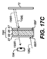
図17C及び図17Dに、それぞれ図17A及び図17Bに示した構成に似ているが、背面66R上に第2の吸収フィルタ層87がある構成を示す。この構成では、右目入射光196Rについての透過率が僅かに低下するのと引き替えに、左目入射光196L,左目入射光186Lが共に多く吸収されることとなる。こうした構成では、左目入射光186Lの反射量が50%未満になるよう、左目入射光186Lの大半を吸収させるのが望ましい。理想的には、右目フィルタ76Rに左目入射光186Lの大半(例.90%超)を吸収させる。
17C and 17D show a configuration similar to that shown in FIGS. 17A and 17B, respectively, but with a second
また、他の構成に従い層を配分することや他の層と併用することもできる。例えば、ダイクロイックフィルタスタック86、吸収フィルタ層87又はその双方の上に更なる保護層を配し、スクラッチ耐性やフェード耐性を付与することができる。第1面反射を抑えるため抗反射被覆を使用することもできる。例えば、ダイクロイックフィルタスタック86の一部をなすこととなるよう、複数個の薄膜層を以て抗反射被覆を形成してもよい。
It is also possible to distribute layers according to other configurations or to use together with other layers. For example, a further protective layer can be provided on the
図18に、吸収フィルタ層87(図17A)が呈しうる右目吸収フィルタ透過率172Rの例を、図16Aに示した右目ダイクロイックフィルタ透過率170Rと共に示す。こうしたスペクトル特性を有するダイクロイックフィルタスタック86及び吸収フィルタ層87を図17A又は図17Bに示したハイブリッドフィルタ配置にて使用した場合、そのハイブリッドフィルタの合成透過率TH(λ)は次の式
TH(λ)≒TD(λ)TA(λ) (3)
で求まる。この式中、TD(λ)はダイクロイックフィルタ透過率、TA(λ)は吸収フィルタ透過率である。(ここでは基板透過率が約1.0であると仮定している。)ハイブリッドフィルタの合成反射率RH(λ)は次の式
RH(λ)≒RD(λ)(TA(λ))2=(1−TD(λ))(TA(λ))2 (4)
で求まる。この式中、RD(λ)はダイクロイックフィルタ反射率であり、式(2)に示したように1−TD(λ)に等しい。この等式は、反射光が吸収フィルタ層87を透過し、ダイクロイックフィルタスタック86によって反射され、吸収フィルタ層87を再度透過する、という仮定に基づいている。これは第1面反射率を無視できるという仮定に通じる。
FIG. 18 shows an example of the right-eye
It is obtained by In this equation, T D (λ) is the dichroic filter transmittance, and T A (λ) is the absorption filter transmittance. (Here, it is assumed that the substrate transmittance is about 1.0.) The combined reflectance R H (λ) of the hybrid filter is expressed by the following equation R H (λ) ≈R D (λ) (T A ( λ)) 2 = (1−T D (λ)) (T A (λ)) 2 (4)
It is obtained by In this equation, R D (λ) is the dichroic filter reflectance, and is equal to 1-T D (λ) as shown in Equation (2). This equation is based on the assumption that the reflected light passes through the
図19Aに、式(3)を用い図18中のスペクトル透過率から計算した右目ハイブリッドフィルタ透過率173Rを示す。右目ハイブリッドフィルタ透過率173Rは一組の右目用スペクトル帯R1,G1,B1及び一組の左目用スペクトル帯R2,G2,B2上に重畳されている。図16Aに図19Aを照らすと、右目ハイブリッドフィルタ透過率173Rが右目ダイクロイックフィルタ透過率170Rによく似ていることがわかる。
FIG. 19A shows the right-eye
図19Bは、右目ハイブリッドフィルタ透過率173Rのもとで右目フィルタ76Rを透過する光と、波長との関係を示すグラフである。この例では、右目用スペクトル帯に属する入射光のうち約81%が右目透過光175Rとなっている。これは、図16Bに示した例即ちダイクロイックオンリの例に比べて僅かに劣化している。しかしながら、左目用スペクトル帯に属する光のうち約1%しか左目透過光175Lになっていない。これは、ダイクロイックオンリの構成に比べ、クロストークの量が約3倍も抑圧されていることを表している。このクロストーク抑圧はハイブリッドフィルタ法の更なる長所である。
FIG. 19B is a graph showing the relationship between the wavelength and the light transmitted through the
図19Cに、式(4)を用い計算された右目ハイブリッドフィルタ反射率174Rを示す。図16Cと比較すると、左目用スペクトル帯R2,G2,B2に対応する波長領域における反射率が顕著に低下していることがわかる。
FIG. 19C shows the right-eye
図19Dは、右目ハイブリッドフィルタ反射率174Rのもとで右目フィルタ76Rから反射される光と、波長との関係を示すグラフである。この例では、右目スペクトル帯に属する入射光のうち7%未満が右目反射光176R、左目用スペクトル帯に属する光のうち約8%が左目反射光176Lとなっている。これは、ダイクロイックオンリの構成に比べ、左目反射光の量が12倍以上も抑圧されていることを表している。これにより、フィルタ眼鏡74からの反射によるフレア光の量が顕著に低減される。
FIG. 19D is a graph showing the relationship between the wavelength of light reflected from the right-
注記すべきことに、吸収フィルタ層87は、その立体イメージングシステムでスペクトル帯交互配置(図12A及び図19A〜図19Dに例示したもの等)が使用されるのかそれとも非交互配置(図12Bに例示したもの等)が使用されるかによらず、ハイブリッドフィルタを構成するダイクロイックフィルタスタック86により提供されるスペクトル分離を補うのに使用することができる。一般的な設計原理は、個々の目に係るフィルタと併用される吸収フィルタ層87が、反対の目に係る像のスペクトル帯をより多く吸収するが、その目に係る像形成光のスペクトル帯をあまり吸収しないようにする、というものである。
It should be noted that the
先に述べた通り、他の看者がまとっているフィルタ眼鏡74からの反射でフレア光が生じると、患者の目に映る投射像のコントラストが低下するほか、立体看取経験に悪影響を及ぼす視覚的ノイズが増す。これを説明するため、図20A及び図20Bに、表示面72からの入射光230の一部が後の看者160がまとっているフィルタ眼鏡74によって反射され、その反射光235が前の看者162がまとっているフィルタ眼鏡74の背面に入射している状況を示す。図15A及び図15Bを参照して説明した通り、この光の一部は前の看者162の目へと後方反射されうる。この現象の現れ方には、後の看者160及び前の看者162の頭部が同じ高さにあるか(図20A)それとも異なる高さにあるか(図20B)によって強弱が生じる。一般的な座席配置の場合、図20Bに示すように、前の看者162の頭部は後の看者160の頭部よりも低い位置になろう。最悪の場合、フィルタ眼鏡74で使用されているダイクロイックフィルタによって、後の看者160の目に送られなかったスペクトル帯に属する光の多く又は全部が反射される。前の看者162が後の看者160の直前且つ同レベルにいる場合、前の看者162がまとっている機能的に同様なフィルタ眼鏡74が、そのフィルタの背面に射突したあらゆる光による間違ったスペクトルコンテンツを高度に反射するため、立体像の質及びコントラストが顕著に劣化する。フィルタ眼鏡74の反射光が前の看者162に係るフィルタ眼鏡74の背面に直に射突しなかった場合でも、その光の一部が投射スクリーンに達する結果、全ての看者にとり画質及びコントラストが劣化する。曲状のフィルタの場合、平坦なフィルタに比べその光を多く散乱させるため、かなりの光がスクリーン上に射突することになる。
As described above, when flare light is generated by the reflection from the
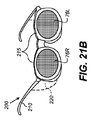
図21A及び図21Bに、本発明の一実施形態に係るフィルタ眼鏡200を示す。この眼鏡200は、右目フィルタ76R及び左目フィルタ76Lにて反射された光による画質劣化が緩和されるよう、その構成が工夫されている。図21Aはフィルタ眼鏡200の側面図、図21Bは斜視図である。この眼鏡200は、反射光の方向を看者位置に対し上向きに転向させることで、後方反射による画質劣化を抑えるように構成されている。反射光は、フィルタ眼鏡200の装着者の前に着席している別の看者や表示面72(図20A)から離れる方向に進んでいく。フレーム210に備わるリム215の働きで、右目フィルタ76R及び左目フィルタ76Lが鉛直方向に対し傾斜角θで配されているため、反射光を上向きに転向させ、フィルタ眼鏡200装着者の前に着席している他の看者から離すことができる。
21A and 21B show
通常の看取環境では、傾斜角θを約5〜20°にするのが望ましい。フィルタ眼鏡200装着者・表示面72間の距離が非常に短い場合は傾斜角を大きめにするとよい。極端な例としては、表示面から約1スクリーン高離れた場所に約1/4スクリーン高の高さで看者が着席している場合がある。この場合、表示面72の下部に発した光がフィルタ眼鏡200に水平線より約14°下の方向から入射する一方、表示面72の上部に発した光がフィルタ眼鏡200に水平線より約37°上の方向から入射する。そのため、全ての反射光を表示面72の上部より上に差し向けるためには、フィルタを、約37°の傾斜角に亘り傾斜させる必要がある。この傾斜角は美的間点からすると現実的でない。大抵の観衆看者はスクリーンに対し中心レベル又はそれ以上にいることを好むので、26°の最大傾斜角にするのがより現実的である。傾斜角θがこのレベルを下回っている場合でも、全看者からスクリーンに戻る光が加算されるので顕著な効果を実現することができる。従って、漏洩光のどのような低減も相応の画質改善につながる。
In a normal viewing environment, it is desirable to set the inclination angle θ to about 5 to 20 °. When the distance between the
左目フィルタ76L及び右目フィルタ76Rがダイクロイックフィルタスタックを備えている場合、前述の通り、一般にスペクトル透過率曲線のエッジ遷移がフィルタの傾斜によってシフトされる。この場合、所望のスペクトル透過特性が得られるようにダイクロイックフィルタの設計を調整するのが望ましい。
When the
実施に当たっては、左目フィルタ76L及び右目フィルタ76Rの背面への漏洩光到達が幾らか阻止されるように、不透明なサイドシールド220をフレーム210に付設するのが望ましい。好ましくは、リム215を成形可能素材で形成し、その成形形状を適宜設定することで傾斜角θを付与するようにする。また、図21Cに示すように、フレーム210にヒンジ機構225を設け、リム215の枢動で傾斜角θを変化させられるようにしてもよい。このようにすることで、看取環境に応じ傾斜角を適宜調整することが可能になる。
In practice, it is desirable to attach an
図示例では、左目フィルタ76L及び右目フィルタ76Rの前面及び背面が実質的に平坦であり、平板として振る舞っている。これとは違い、左目フィルタ76L及び右目フィルタ76Rを曲板とし、例えば球面状又は非球面状の曲面を呈するように構成してもよい。この場合、傾斜角は、その曲面に最適フィットする平面を基準に定義される。
In the illustrated example, the front and back surfaces of the
図22及び図23に、本発明の一実施形態に係るフィルタ眼鏡200を後の看者160及び前の看者162が装着している状況を示す。フィルタ眼鏡200のリム215は、左目フィルタ76L及び右目フィルタ76Rを相応の傾斜角で傾斜させるように構成されている。即ち、表示面72(図22では省略)からの入射光230が後の看者160のフィルタ眼鏡200に備わる左目フィルタ76L及び右目フィルタ76Rによって反射されることにより生じる反射光235が、他の看者例えば前の看者162の頭部より上に差し向けられるように構成されている。結果として、後の看者160に係るフィルタ眼鏡200からの反射光235が、前の看者162により看取される画像の質に悪影響を及ぼすことが少ない。好ましくは、反射光235が表示面72の上部よりも上に差し向けられるようにする。表示される画像にフレア光が加わらないようにするためである。
FIG. 22 and FIG. 23 show a situation in which the
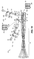
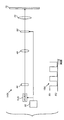
本発明の他の実施形態においては、1個又は複数個の可調光源を有しており少なくとも1個の色チャネルで別々のスペクトル帯を提供可能な立体イメージング装置が提供される。図24に、赤色可調光輻射器152r例えば可調狭帯域固体レーザを有する赤色イメージングチャネル140rの構成を模式的に示す。赤色可調光輻射器152rは、複数個の異なる状態にて選択的に光を輻射する。第1の状態にて赤色可調光輻射器152rから輻射される光は右目像形成用のスペクトル帯R1に属する光であり、第2の状態にて赤色可調光輻射器152rから輻射される光は左目像形成用のスペクトル帯R2に属する光である。タイミングチャート154に示すように、コントローラシステム80は、所定の時間的シーケンスに従い赤色可調光輻射器152rを制御しスペクトル帯R1及びR2の光を交番的に輻射させる。看者にそのスイッチングを察知されないようにするため、赤色可調光輻射器152rの色状態は、高速例えば約60Hzでスイッチングさせるようにする必要がある。
In another embodiment of the present invention, a stereoscopic imaging apparatus is provided that has one or more adjustable light sources and is capable of providing separate spectral bands with at least one color channel. FIG. 24 schematically shows a configuration of a
輻射された光は、光学部品(例えばユニフォマイジング光学系44や1個又は複数個のレンズ)によって調光された後に、空間光変調器60に入射する。空間光変調器60を構成する画素群は、対応する像即ち右目像又は左目像に係る画像データに従い、コントローラシステム80によって同期制御される。その結果生じた像は、前述の通り、投射光学系70を用い表示面72上に投射される。
The radiated light is adjusted by an optical component (for example, the uniformizing
図25に、赤色イメージングチャネル140r、緑色イメージングチャネル140g及び青色イメージングチャネル140bを有するカラー立体イメージングシステム150の構成を示す。このシステムでは、図24に示した赤色可調光輻射器152rと並び緑色可調光輻射器152g及び青色可調光輻射器152bが使用されている。緑色可調光輻射器152g及び青色可調光輻射器152bは、右目コンテンツ像コンテンツ及び左目像コンテンツを提供すべく、それぞれ緑色チャネル及び青色チャネルで使用される。各可調光輻射器は、同一基本色(赤、緑又は青)に属する少なくとも二通りのスペクトル帯で光を輻射する。この場合、投射光学系70がビーム結合系、例えば図9に示したダイクロイック結合器82を有する構成にするとよい。
FIG. 25 shows a configuration of a color
ご理解頂けるように、可調光輻射器を使用する立体イメージングシステム150は、複数個の光源又は(単一の多色乃至白色光源から来る光をフィルタリングするため)複数バンクのフィルタを必要とする他種の波長ベースイメージングシステムに比し秀でている。例えば、図5に示した構成では光輻射器が6個必要であるが図25に示した構成では3個でよい。更に、図5に示した構成では、2個の色状態間のスイッチングのため3個のビーム走査器50が必要となる。
As can be appreciated,
ある種の可調光輻射器に備わる別の有益な特徴は、複数同時モードの生成、高周波モードホッピング又は中央スペクトル帯周りでの高周波チューニングを通じ、中心波長周りで幾ばくかの波長ジッタを提供するのに使用でき、各時点で輻射光の波長を変化させうることである。この場合、コントローラシステム80による制御のもと可調光輻射器が第1状態で動作しているときに、第1スペクトル帯内の相異なるピーク波長にて光を順次発生させるよう可調光輻射器を構成することができる。また、可調光輻射器が第2状態で動作しているときに、第1スペクトル帯にスペクトル隣接する第2スペクトル帯内の相異なるピーク波長にて光を順次発生させるよう可調光輻射器を構成することができる。スペクトル帯構成波長域におけるスペクトル出力のランダム性は、高コヒーレント光がもたらす悪影響、例えば多くのレーザ投射システムに見られるスペックルを抑えるのに役立つ。
Another useful feature of some adjustable optical radiators is that it provides some wavelength jitter around the center wavelength through multiple simultaneous mode generation, high frequency mode hopping or high frequency tuning around the central spectral band. The wavelength of the radiant light can be changed at each time point. In this case, when the adjustable light radiator is operating in the first state under the control of the
図25中の赤色、緑色及び青色可調光輻射器152r、152g及び152bとしては、本件技術分野で既知の様々な可調光源を使用することができる。例えば、可調光輻射器として、可調発光ダイオード(LED)、可調レーザ等の固体光源を使用することができる。可調レーザにおける輻射出力波長切替機構としては、様々な機構を使用することができる。そのうち一つは、非特許文献5記載の如く、複数通りの機械状態間で迅速にスイッチングすることが可能な微細電気機械システム(MEMS)デバイスを用い、光発振器を制御する、という機構である。同文献に記載の装置では、静電的に駆動される誘電ミラーをレーザ構造の上方に懸架し、それを用い波長を調整するようにしている。
As the red, green, and blue
好適な可調レーザを提供する方法としては、バイステーブルレーザを使用する方法がある。非特許文献6には、50psec(ピコ秒)の整数倍でスイッチングされる2セクションモードロックド量子ドットレーザの使用が開示されている。この装置の動作は、利得及びアブゾーバにおけるクロスサチュレーション及びセルフサチュレーション特性と、アブゾーバにおける量子コンファインドスターク効果との相互作用に基づいている。この種のレーザは、電流注入レベル又は電圧レベルを変化させることで容易にチューニングすることができる。 One method for providing a suitable tunable laser is to use a bistable laser. Non-Patent Document 6 discloses the use of a two-section mode locked quantum dot laser that is switched at an integer multiple of 50 psec (picoseconds). The operation of this device is based on the interaction between gain and cross-saturation and self-saturation characteristics in the absorber and the quantum confined Stark effect in the absorber. This type of laser can be easily tuned by changing the current injection level or voltage level.
本発明で使用可能な可調LEDとしては、例えば非特許文献7に記載のデバイスがある。このデバイスは、ガリウム窒素ナノロッドをインジウムガリウム窒素の層で被覆し量子井戸を形成する、という仕組みを採っている。その形成時に層の厚みに自然に差が生じるので、印加電圧を変化させることにより、別々の層に電流を注入して輻射光の色を変化させることができる。 As an adjustable LED that can be used in the present invention, for example, there is a device described in Non-Patent Document 7. This device employs a mechanism in which a gallium nitrogen nanorod is covered with a layer of indium gallium nitrogen to form a quantum well. Since there is a natural difference in the thickness of the layers during the formation, the color of the radiant light can be changed by injecting a current into different layers by changing the applied voltage.
以上、その好適な実施形態を参照しつつ本発明に関し詳細に説明したが、本発明の技術的範囲を逸脱することなく様々な変形及び修正を施せる点をご理解頂きたい。例えば、諸実施形態で使用される光輻射器は本件技術分野で既知のどのような種類のものであってもよい。例えば、レーザその他の発光デバイスからなるアレイ等である。その出射光を同一の光軸上に結合させる手段としては、プリズム以外の結合光学系も使用することができる。 Although the present invention has been described in detail with reference to the preferred embodiments, it should be understood that various changes and modifications can be made without departing from the technical scope of the present invention. For example, the light radiator used in the embodiments may be of any type known in the art. For example, an array of lasers or other light emitting devices. As a means for coupling the emitted light on the same optical axis, a coupling optical system other than a prism can also be used.
別紙模式図では光学系をレンズ乃至ブロックとして表記したが、それ以外にも様々な光学部品を使用することができる。照明光乃至イメージング光を相応に導波し調整することができればよい。 In the schematic diagram of the attached sheet, the optical system is described as a lens or a block, but various other optical components can be used. It is sufficient if the illumination light or imaging light can be guided and adjusted accordingly.
各色チャネル内の空間光変調器60としては、様々なタイプの空間光変調器を使用することができる。例えば、米国テキサス州ダラス所在のTexas Instrumentsが製造しているディジタル光プロセッサ(DLP;登録商標,ディジタルマイクロミラーアレイの一種)等のほか、液晶アレイも使用することができる。
Various types of spatial light modulators can be used as the spatial
実施に際しては、左目用に1個、右目用に1個というように、色チャネル内に2個の空間光変調器を設け、都合6個の空間光変調器を用いディジタル立体投射システムを構成することができる。或いは、図5に示すように各色チャネル毎に1個の空間変調器を設け、左目像コンテンツと右目像コンテンツでそれらを共用するようにしてもよい。共用する手法としては、色スクローリング等のリソース共有手法を使用することができる。例えば、タイミングパターンに従い複数通りのスペクトル帯を交互にアクティベートする手法である。 In implementation, two spatial light modulators are provided in the color channel, such as one for the left eye and one for the right eye, and a digital stereoscopic projection system is constructed using convenient six spatial light modulators. be able to. Alternatively, as shown in FIG. 5, one spatial modulator may be provided for each color channel, and the left-eye image content and the right-eye image content may be shared. As a sharing technique, a resource sharing technique such as color scrolling can be used. For example, it is a method of activating a plurality of spectrum bands alternately according to a timing pattern.
実施に際しては、照明光路上で更なるフィルタリングを施すことで1個又は複数個の光輻射器からのスペクトル成分を減衰させ、スペクトル隣接帯域同士が実質的に重複しないようにすることもできる。 In implementation, the spectral components from one or more light radiators can be attenuated by further filtering on the illumination light path, so that the spectral adjacent bands do not substantially overlap.
本発明について、表示スクリーン上に画像を投射するディジタル立体投射システムを例に説明してきたが、いわゆる当業者には自明な通り、本発明は投射を伴わない他種ディジタル立体表示システムにも適用することができる。例えば、ディジタル立体ソフトコピーディスプレイを用い、表示面に左目像及び右目像からなる立体像を直に形成することができる。ソフトコピーディスプレイとしては、本件技術分野で既知の様々な種類の表示技術、例えばLEDディスプレイやLCDディスプレイを使用することができる。 The present invention has been described by taking a digital stereoscopic projection system that projects an image on a display screen as an example, but as is obvious to those skilled in the art, the present invention is also applicable to other types of digital stereoscopic display systems that do not involve projection. be able to. For example, using a digital stereoscopic soft copy display, a stereoscopic image composed of a left eye image and a right eye image can be directly formed on the display surface. As the soft copy display, various kinds of display technologies known in the technical field, such as an LED display and an LCD display, can be used.
12 光源、12L 左目光輻射器、12R 右目光輻射器、18 光学系、20 空間光変調器、28a〜28e,38,38a〜38e 画像フレーム、30 光転向プリズム、32 画像領域、34b,34g,34r,35b,35g,35r,36a,36b 帯域光、40r 赤色チャネル、40g 緑色チャネル、40b 青色チャネル、41L 左目像形成システム、41R 右目像形成システム、42a,42b,43L,43R 光源、44 ユニフォマイジング光学系、46 ビーム結合器、48 レンズ、50 ビーム走査器、52 回転プリズム、54 レンズレットアレイ、56 不透明ブロック、58 インテグレーティングバー、60,60L,60R 空間光変調器、62,210 フレーム、66F 前面、66R 背面、68,84 ダイクロイック面、70 投射光学系、72 表示面、74,200 フィルタ眼鏡、75 重複領域、76L 左目フィルタ、76R 右目フィルタ、77B 帯域通過フィルタ透過帯、77E エッジフィルタ透過帯、78L,79L 左目フィルタ透過率、78R,79R 右目フィルタ透過率、80 コントローラシステム、82 ダイクロイック結合器、86 ダイクロイックフィルタスタック、87 吸収フィルタ層、88 基板、90 照明光学系、92 ビーム走査光学系、94 第1段、96 第2段、100,110 ディジタル立体投射システム、120 プロジェクタ装置、130,135 グラフ、140b 青色イメージングチャネル、140g 緑色イメージングチャネル、140r 赤色イメージングチャネル、150 立体イメージングシステム、152b 青色可調光輻射器、152g 緑色可調光輻射器、152r 赤色可調光輻射器、154 タイミングチャート、160 後の看者、162 前の看者、170R 右目ダイクロイックフィルタ透過率、171R 右目ダイクロイックフィルタ反射率、172R 右目吸収フィルタ透過率、173R 右目ハイブリッドフィルタ透過率、174R 右目ハイブリッドフィルタ反射率、175R,198R 右目透過光、175L 左目透過光、176R 右目反射光、176L,187L,197L 左目反射光、186L,196L 左目入射光、194 右目、196R 右目入射光、215 リム、220 サイドシールド、225 ヒンジ機構、230 入射光、235 反射光、A1 光源面積、A2 変調器面積、B,B1,B2,G,G1,G2,R,R1,R2 スペクトル帯、O 軸、S 波長差、θ 傾斜角、θ1 光源出射角幅、θ2 変調器入射角幅。 12 light source, 12L left eye light radiator, 12R right eye light radiator, 18 optical system, 20 spatial light modulator, 28a-28e, 38, 38a-38e image frame, 30 light turning prism, 32 image area, 34b, 34g, 34r, 35b, 35g, 35r, 36a, 36b Band light, 40r Red channel, 40g Green channel, 40b Blue channel, 41L Left eye image forming system, 41R Right eye image forming system, 42a, 42b, 43L, 43R Light source, 44 Uniforme Zing optics, 46 beam combiner, 48 lens, 50 beam scanner, 52 rotating prism, 54 lenslet array, 56 opaque block, 58 integrating bar, 60, 60L, 60R spatial light modulator, 62, 210 frame, 66F front, 66R back 68,84 Dichroic surface, 70 Projection optical system, 72 Display surface, 74,200 Filter glasses, 75 Overlap area, 76L Left eye filter, 76R Right eye filter, 77B Band pass filter transmission band, 77E Edge filter transmission band, 78L, 79L Left eye Filter transmittance, 78R, 79R Right eye filter transmittance, 80 controller system, 82 dichroic coupler, 86 dichroic filter stack, 87 absorption filter layer, 88 substrate, 90 illumination optical system, 92 beam scanning optical system, 94 1st stage, 96 Second Stage, 100, 110 Digital Stereo Projection System, 120 Projector Device, 130, 135 Graph, 140b Blue Imaging Channel, 140g Green Imaging Channel, 140r Red Imaging Channel 150 Stereo Imaging System, 152b Blue Adjustable Light Radiator, 152g Green Adjustable Light Radiator, 152r Red Adjustable Light Radiator, 154 Timing Chart, 160 Rear Viewer, 162 Front Viewer, 170R Right Eye Dichroic Filter Transmission 171R Right eye dichroic filter reflectance, 172R Right eye absorption filter transmittance, 173R Right eye hybrid filter transmittance, 174R Right eye hybrid filter reflectance, 175R, 198R Right eye transmitted light, 175L Left eye transmitted light, 176R Right eye reflected light, 176L, 187L , 197L Left eye reflected light, 186L, 196L Left eye incident light, 194 Right eye, 196R Right eye incident light, 215 Rim, 220 Side shield, 225 Hinge mechanism, 230 Incident light, 235 Reflected light, A1 Light source area, A 2 Modulator area, B, B1, B2, G, G1, G2, R, R1, R2 spectrum band, O axis, S wavelength difference, θ tilt angle, θ1 light source exit angle width, θ2 modulator incident angle width.
Claims (19)
対応する第1スペクトル帯及び第1中心波長を有する第1状態で輻射光を提供する動作並びに対応する第2スペクトル帯及び第2中心波長を有する第2状態で輻射光を提供する動作を交番的に実行するよう制御可能で、第1スペクトル帯と第2スペクトル帯との間に実質的に重複がない1個又は複数個の狭帯域固体可調光輻射器と、
可調輻射器からの光を変調することで変調像を生成する空間光変調器であって、それぞれ一群の可制御な空間光変調器画素を有するものを、1個又は複数個備える画像形成システムと、
可調光輻射器の状態及び空間光変調器画素を同期制御するコントローラであって、可調光輻射器が第1状態にあるとき第1像に係る画像データに従い空間光変調器画素を制御し第1目変調像をもたらす一方、可調光輻射器が第2状態にあるとき第2像に係る画像データに従い空間光変調器画素を制御し第2目変調像をもたらすコントローラと、
第1目変調像及び第2目変調像を表示面に供給する投射光学系と、
を備えるディジタル立体投射システム。 A digital stereoscopic projection system for projecting a stereoscopic image having a first eye image and a second eye image on a display surface,
The operation of providing radiant light in a first state having a corresponding first spectral band and first central wavelength and the operation of providing radiant light in a second state having a corresponding second spectral band and second central wavelength are alternated. One or more narrowband solid-state tunable light radiators that are controllable to perform at substantially no overlap between the first and second spectral bands;
Image forming system comprising one or a plurality of spatial light modulators that generate a modulated image by modulating light from an adjustable radiator, each having a group of controllable spatial light modulator pixels When,
A controller that synchronously controls the state of the adjustable light radiator and the spatial light modulator pixel, and controls the spatial light modulator pixel according to the image data relating to the first image when the adjustable light radiator is in the first state. A controller that provides a first modulated image while providing a second modulated image by controlling the spatial light modulator pixels according to the image data associated with the second image when the adjustable light radiator is in the second state while providing the first modulated image.
A projection optical system for supplying a first modulated image and a second modulated image to the display surface;
A digital stereoscopic projection system comprising:
対応する第1赤色スペクトル帯を有する第1状態で輻射光を提供する動作並びに対応する第2赤色スペクトル帯を有する第2状態で輻射光を提供する動作を交番的に実行するよう制御可能な赤色可調光輻射器と、
対応する第1緑色スペクトル帯を有する第1状態で輻射光を提供する動作並びに対応する第2緑色スペクトル帯を有する第2状態で輻射光を提供する動作を交番的に実行するよう制御可能な緑色可調光輻射器と、
対応する第1青色スペクトル帯を有する第1状態で輻射光を提供する動作並びに対応する第2青色スペクトル帯を有する第2状態で輻射光を提供する動作を交番的に実行するよう制御可能な青色可調光輻射器と、
を備え、第1状態で輻射するよう赤色、緑色及び青色可調光輻射器を制御することにより第1目変調像を発生させる一方、第2状態で輻射するよう赤色、緑色及び青色可調光輻射器を制御することにより第2目変調像を発生させるディジタル立体投射システム。 The digital stereoscopic projection system according to claim 1, wherein the narrowband solid tunable light radiator is:
Red color controllable to alternately perform the operation of providing radiant light in a first state having a corresponding first red spectral band and the operation of providing radiant light in a second state having a corresponding second red spectral band. An adjustable light radiator,
Green that is controllable to alternately perform the operation of providing radiant light in a first state having a corresponding first green spectral band and the operation of providing radiant light in a second state having a corresponding second green spectral band. An adjustable light radiator,
Blue color controllable to alternately perform the operation of providing radiant light in a first state having a corresponding first blue spectral band and the operation of providing radiant light in a second state having a corresponding second blue spectral band. An adjustable light radiator,
A red, green and blue adjustable light radiator to emit in the first state to generate a first eye modulated image, while red, green and blue adjustable light to emit in the second state A digital stereoscopic projection system that generates a second modulated image by controlling a radiator.
第1状態で光を輻射するよう1個又は複数個の可変光輻射器が制御されているときその可変光輻射器からの光のうち50%超を透過させる一方、第2状態で光を輻射するよう1個又は複数個の可変光輻射器が制御されているときその可変光輻射器からの光のうち5%未満を透過させる第1目フィルタと、
第2状態で光を輻射するよう1個又は複数個の可変光輻射器が制御されているときその可変光輻射器からの光のうち50%超を透過させる一方、第1状態で光を輻射するよう1個又は複数個の可変光輻射器が制御されているときその可変光輻射器からの光のうち5%未満を透過させる第2目フィルタと、
第1目フィルタが看者の第1目の面前に位置すると共に第2目フィルタが看者の第2目の面前に位置することとなるよう第1目フィルタ及び第2目フィルタが実装されるフレームと、
を有するフィルタ眼鏡を備えるディジタル立体投射システム。 The digital stereoscopic projection system according to claim 1, further comprising:
When one or more variable light radiators are controlled to radiate light in the first state, more than 50% of the light from the variable light radiator is transmitted while radiating light in the second state A first filter that transmits less than 5% of the light from the variable light radiator when one or more variable light radiators are being controlled;
When one or more variable light radiators are controlled to emit light in the second state, more than 50% of the light from the variable light radiator is transmitted while radiating light in the first state A second filter that transmits less than 5% of the light from the variable light radiator when one or more variable light radiators are being controlled;
The first and second filters are mounted such that the first filter is located in front of the viewer's first face and the second filter is located in front of the viewer's second face. Frame,
Stereoscopic projection system comprising filter glasses having
対応する第1スペクトル帯及び第1中心波長を有する第1状態で輻射光を提供する動作並びに対応する第2スペクトル帯及び第2中心波長を有する第2状態で輻射光を提供する動作を交番的に実行するよう制御可能で、第1スペクトル帯と第2スペクトル帯との間に実質的に重複がない1個又は複数個の狭帯域固体可調光輻射器と、
可調輻射器から来る光の強度を変調させることで表示面上に表示像を生成する一群の可制御画素を有する画像表示システムと、
可調光輻射器の状態及び可制御画素を同期制御するコントローラであって、可調光輻射器が第1状態にあるとき第1像に係る画像データに従い可制御画素を制御し第1目変調像をもたらす一方、可調光輻射器が第2状態にあるとき第2像に係る画像データに従い可制御画素を制御し第2目変調像をもたらすコントローラと、
を備えるディジタル立体表示システム。 A digital stereoscopic display system for displaying a stereoscopic image having a first eye image and a second eye image on a display surface,
The operation of providing radiant light in a first state having a corresponding first spectral band and first central wavelength and the operation of providing radiant light in a second state having a corresponding second spectral band and second central wavelength are alternated. One or more narrowband solid-state tunable light radiators that are controllable to perform at substantially no overlap between the first and second spectral bands;
An image display system having a group of controllable pixels that generate a display image on the display surface by modulating the intensity of light coming from the adjustable radiator;
A controller for synchronously controlling the state of the adjustable light radiator and the controllable pixel, wherein the controllable pixel is controlled according to the image data relating to the first image when the adjustable light radiator is in the first state to modulate the first eye A controller that provides an image while controlling the controllable pixels according to the image data associated with the second image when the adjustable light radiator is in the second state to provide a second modulated image;
A digital stereoscopic display system comprising:
Applications Claiming Priority (3)
| Application Number | Priority Date | Filing Date | Title |
|---|---|---|---|
| US13/351,470 US8864314B2 (en) | 2012-01-17 | 2012-01-17 | Stereoscopic projection system using tunable light emitters |
| US13/351,470 | 2012-01-17 | ||
| PCT/US2013/020736 WO2013109440A1 (en) | 2012-01-17 | 2013-01-09 | Stereoscopic projection system using tunable light emitters |
Publications (2)
| Publication Number | Publication Date |
|---|---|
| JP2015508611A true JP2015508611A (en) | 2015-03-19 |
| JP2015508611A5 JP2015508611A5 (en) | 2016-01-28 |
Family
ID=47604199
Family Applications (1)
| Application Number | Title | Priority Date | Filing Date |
|---|---|---|---|
| JP2014552257A Pending JP2015508611A (en) | 2012-01-17 | 2013-01-09 | Stereoscopic projection system using adjustable light radiator |
Country Status (5)
| Country | Link |
|---|---|
| US (1) | US8864314B2 (en) |
| EP (1) | EP2805518A1 (en) |
| JP (1) | JP2015508611A (en) |
| CN (1) | CN104054336A (en) |
| WO (1) | WO2013109440A1 (en) |
Cited By (1)
| Publication number | Priority date | Publication date | Assignee | Title |
|---|---|---|---|---|
| US11399162B2 (en) | 2018-12-28 | 2022-07-26 | Appotronics Corporation Limited | Display system |
Families Citing this family (7)
| Publication number | Priority date | Publication date | Assignee | Title |
|---|---|---|---|---|
| US8746888B2 (en) * | 2011-10-03 | 2014-06-10 | Eastman Kodak Company | Stereoscopic projector using spectrally-adjacent color bands |
| TWI546607B (en) * | 2012-12-13 | 2016-08-21 | 鴻海精密工業股份有限公司 | Laser projection device |
| JP6107716B2 (en) * | 2014-03-19 | 2017-04-05 | マツダ株式会社 | Vehicle control device and vehicle password setting method |
| CN105025279B (en) * | 2014-04-24 | 2017-03-01 | 深圳市绎立锐光科技开发有限公司 | A kind of light-source system and projection display equipment |
| WO2016011165A1 (en) | 2014-07-15 | 2016-01-21 | Senseonics, Incorporated | Integrated optical filter system with low sensitivity to high angle of incidence light for an analyte sensor |
| CN106796661B (en) | 2014-08-12 | 2020-08-25 | 曼蒂斯影像有限公司 | System, method and computer program product for projecting a light pattern |
| CN105549314B (en) * | 2016-03-09 | 2017-06-16 | 京东方科技集团股份有限公司 | Projection display apparatus |
Citations (5)
| Publication number | Priority date | Publication date | Assignee | Title |
|---|---|---|---|---|
| JPS61144691A (en) * | 1984-12-19 | 1986-07-02 | 富士通株式会社 | 3-d dispaly unit |
| JPH0278393A (en) * | 1988-09-14 | 1990-03-19 | Hitachi Ltd | Stereoscopic color picture display device |
| JP2009229596A (en) * | 2008-03-19 | 2009-10-08 | Seiko Epson Corp | Image display apparatus |
| WO2010099707A1 (en) * | 2009-03-06 | 2010-09-10 | 上海三鑫科技发展有限公司 | Laser optical engine |
| JP2011510333A (en) * | 2007-12-14 | 2011-03-31 | イーストマン コダック カンパニー | Projector using separate multi-wavelength light sources |
Family Cites Families (27)
| Publication number | Priority date | Publication date | Assignee | Title |
|---|---|---|---|---|
| US4734756A (en) | 1981-12-31 | 1988-03-29 | 3-D Video Corporation | Stereoscopic television system |
| US5165077A (en) * | 1989-02-28 | 1992-11-17 | Fujitsu Limited | Optical drop-and-insert apparatus |
| EP0909517B1 (en) | 1997-04-30 | 2011-07-20 | Infitec GmbH | Method and facility for light-beam projection of images on a screen |
| DE19808264C2 (en) | 1997-04-30 | 2000-04-06 | Helmut Jorke | Method for producing stereocopic color images with high image contrast |
| US6967778B1 (en) | 1998-01-13 | 2005-11-22 | 3M Innovative Properties Co. | Optical film with sharpened bandedge |
| US6547396B1 (en) | 2001-12-27 | 2003-04-15 | Infocus Corporation | Stereographic projection system |
| US6970488B2 (en) * | 2002-10-16 | 2005-11-29 | Eastman Kodak Company | Tunable organic VCSEL system |
| ATE415786T1 (en) | 2003-10-21 | 2008-12-15 | Barco Nv | METHOD AND DEVICE FOR PERFORMING A STEREOSCOPIC IMAGE DISPLAY BASED ON COLOR SELECTIVE FILTERS |
| US7147332B2 (en) | 2004-07-21 | 2006-12-12 | 3M Innovative Properties Company | Projection system with scrolling color illumination |
| US20070236809A1 (en) | 2006-04-05 | 2007-10-11 | Barret Lippey | Forming spectral filters |
| US8730306B2 (en) * | 2006-04-25 | 2014-05-20 | Corporation For Laser Optics Research | 3-D projection full color multimedia display |
| JP4441918B2 (en) * | 2006-08-31 | 2010-03-31 | セイコーエプソン株式会社 | Light source device and image display device |
| DE102006054713B4 (en) | 2006-11-19 | 2012-08-30 | Infitec Gmbh | Stereo projection with interference filters |
| US20080151193A1 (en) | 2006-12-26 | 2008-06-26 | Texas Instruments Incorporated | Stereoscopic imaging systems utilizing solid-state illumination and passive glasses |
| US7784938B2 (en) | 2007-05-09 | 2010-08-31 | Dolby Laboratories Licensing Corporation | Method and system for shaped glasses and viewing 3D images |
| US7959295B2 (en) | 2007-05-18 | 2011-06-14 | Dolby Laboratories Licensing Corporation | Spectral separation filters for 3D stereoscopic D-cinema presentation |
| TWI539230B (en) * | 2007-05-09 | 2016-06-21 | 杜比實驗室特許公司 | System for 3d image projections and viewing |
| EP2188874A2 (en) * | 2007-08-16 | 2010-05-26 | Philips Intellectual Property & Standards GmbH | Switchable dual wavelength solid state laser |
| US7649918B2 (en) * | 2007-10-30 | 2010-01-19 | Corning Incorporated | Multi-component wavelength conversion devices and lasers incorporating the same |
| US7871165B2 (en) * | 2007-11-30 | 2011-01-18 | Eastman Kodak Company | Stereo projection apparatus using polarized solid state light sources |
| US8029139B2 (en) * | 2008-01-29 | 2011-10-04 | Eastman Kodak Company | 2D/3D switchable color display apparatus with narrow band emitters |
| US7891816B2 (en) | 2008-02-25 | 2011-02-22 | Eastman Kodak Company | Stereo projection using polarized solid state light sources |
| US8016422B2 (en) | 2008-10-28 | 2011-09-13 | Eastman Kodak Company | Etendue maintaining polarization switching system and related methods |
| EP2227027A3 (en) | 2009-03-04 | 2012-04-04 | JDS Uniphase Corporation | Three-dimensional (3D) color display system |
| US8203600B2 (en) * | 2009-06-04 | 2012-06-19 | Transpacific Image, Llc | Projection-type stereoscopic display |
| US20110063726A1 (en) | 2009-09-12 | 2011-03-17 | Monte Jerome Ramstad | Interference filters for viewing anaglyphs |
| US20110080108A1 (en) * | 2009-10-06 | 2011-04-07 | Walsin Lihwa Corporation | Color tunable light emitting diode |
-
2012
- 2012-01-17 US US13/351,470 patent/US8864314B2/en active Active
-
2013
- 2013-01-09 EP EP13701164.9A patent/EP2805518A1/en not_active Withdrawn
- 2013-01-09 WO PCT/US2013/020736 patent/WO2013109440A1/en active Application Filing
- 2013-01-09 JP JP2014552257A patent/JP2015508611A/en active Pending
- 2013-01-09 CN CN201380005840.0A patent/CN104054336A/en active Pending
Patent Citations (5)
| Publication number | Priority date | Publication date | Assignee | Title |
|---|---|---|---|---|
| JPS61144691A (en) * | 1984-12-19 | 1986-07-02 | 富士通株式会社 | 3-d dispaly unit |
| JPH0278393A (en) * | 1988-09-14 | 1990-03-19 | Hitachi Ltd | Stereoscopic color picture display device |
| JP2011510333A (en) * | 2007-12-14 | 2011-03-31 | イーストマン コダック カンパニー | Projector using separate multi-wavelength light sources |
| JP2009229596A (en) * | 2008-03-19 | 2009-10-08 | Seiko Epson Corp | Image display apparatus |
| WO2010099707A1 (en) * | 2009-03-06 | 2010-09-10 | 上海三鑫科技发展有限公司 | Laser optical engine |
Cited By (1)
| Publication number | Priority date | Publication date | Assignee | Title |
|---|---|---|---|---|
| US11399162B2 (en) | 2018-12-28 | 2022-07-26 | Appotronics Corporation Limited | Display system |
Also Published As
| Publication number | Publication date |
|---|---|
| CN104054336A (en) | 2014-09-17 |
| US8864314B2 (en) | 2014-10-21 |
| WO2013109440A1 (en) | 2013-07-25 |
| US20130182226A1 (en) | 2013-07-18 |
| EP2805518A1 (en) | 2014-11-26 |
Similar Documents
| Publication | Publication Date | Title |
|---|---|---|
| JP6033330B2 (en) | Stereoscopic glasses with tilt filter | |
| JP6080865B2 (en) | Stereoscopic glasses having a dichroic layer and an absorption layer | |
| JP5964436B2 (en) | Stereo projector using spectrally adjacent color bands | |
| JP2015508611A (en) | Stereoscopic projection system using adjustable light radiator | |
| JP5416129B2 (en) | 3D digital image projector | |
| US8947424B2 (en) | Spectral stereoscopic projection system | |
| US9291830B2 (en) | Multiview projector system | |
| US20130182321A1 (en) | Filter glasses for spectral stereoscopic projection system | |
| US20140063466A1 (en) | Projection apparatus | |
| US20130141553A1 (en) | Light source module for stereoscopic display, imaging device for stereoscopic display and stereoscopic display system | |
| JP6515589B2 (en) | Projector and transmission type display device | |
| US8651663B2 (en) | Stereoscopic projector using scrolling color bands | |
| JP2014211585A (en) | Projection type display device and adaptor |
Legal Events
| Date | Code | Title | Description |
|---|---|---|---|
| A521 | Request for written amendment filed |
Free format text: JAPANESE INTERMEDIATE CODE: A523 Effective date: 20151203 |
|
| A621 | Written request for application examination |
Free format text: JAPANESE INTERMEDIATE CODE: A621 Effective date: 20151203 |
|
| A977 | Report on retrieval |
Free format text: JAPANESE INTERMEDIATE CODE: A971007 Effective date: 20160810 |
|
| A131 | Notification of reasons for refusal |
Free format text: JAPANESE INTERMEDIATE CODE: A131 Effective date: 20160830 |
|
| A02 | Decision of refusal |
Free format text: JAPANESE INTERMEDIATE CODE: A02 Effective date: 20170404 |