JP2015508564A - Built-in battery cell with new structure - Google Patents
Built-in battery cell with new structure Download PDFInfo
- Publication number
- JP2015508564A JP2015508564A JP2014552138A JP2014552138A JP2015508564A JP 2015508564 A JP2015508564 A JP 2015508564A JP 2014552138 A JP2014552138 A JP 2014552138A JP 2014552138 A JP2014552138 A JP 2014552138A JP 2015508564 A JP2015508564 A JP 2015508564A
- Authority
- JP
- Japan
- Prior art keywords
- battery cell
- battery
- coating layer
- protective coating
- battery case
- Prior art date
- Legal status (The legal status is an assumption and is not a legal conclusion. Google has not performed a legal analysis and makes no representation as to the accuracy of the status listed.)
- Granted
Links
Images

Classifications
-
- H—ELECTRICITY
- H01—ELECTRIC ELEMENTS
- H01M—PROCESSES OR MEANS, e.g. BATTERIES, FOR THE DIRECT CONVERSION OF CHEMICAL ENERGY INTO ELECTRICAL ENERGY
- H01M10/00—Secondary cells; Manufacture thereof
- H01M10/04—Construction or manufacture in general
- H01M10/0431—Cells with wound or folded electrodes
-
- H—ELECTRICITY
- H01—ELECTRIC ELEMENTS
- H01M—PROCESSES OR MEANS, e.g. BATTERIES, FOR THE DIRECT CONVERSION OF CHEMICAL ENERGY INTO ELECTRICAL ENERGY
- H01M50/00—Constructional details or processes of manufacture of the non-active parts of electrochemical cells other than fuel cells, e.g. hybrid cells
- H01M50/10—Primary casings; Jackets or wrappings
- H01M50/116—Primary casings; Jackets or wrappings characterised by the material
- H01M50/124—Primary casings; Jackets or wrappings characterised by the material having a layered structure
- H01M50/1245—Primary casings; Jackets or wrappings characterised by the material having a layered structure characterised by the external coating on the casing
-
- H—ELECTRICITY
- H01—ELECTRIC ELEMENTS
- H01M—PROCESSES OR MEANS, e.g. BATTERIES, FOR THE DIRECT CONVERSION OF CHEMICAL ENERGY INTO ELECTRICAL ENERGY
- H01M50/00—Constructional details or processes of manufacture of the non-active parts of electrochemical cells other than fuel cells, e.g. hybrid cells
- H01M50/10—Primary casings; Jackets or wrappings
- H01M50/116—Primary casings; Jackets or wrappings characterised by the material
- H01M50/117—Inorganic material
- H01M50/119—Metals
-
- H—ELECTRICITY
- H01—ELECTRIC ELEMENTS
- H01M—PROCESSES OR MEANS, e.g. BATTERIES, FOR THE DIRECT CONVERSION OF CHEMICAL ENERGY INTO ELECTRICAL ENERGY
- H01M50/00—Constructional details or processes of manufacture of the non-active parts of electrochemical cells other than fuel cells, e.g. hybrid cells
- H01M50/10—Primary casings; Jackets or wrappings
- H01M50/116—Primary casings; Jackets or wrappings characterised by the material
- H01M50/121—Organic material
-
- H—ELECTRICITY
- H01—ELECTRIC ELEMENTS
- H01M—PROCESSES OR MEANS, e.g. BATTERIES, FOR THE DIRECT CONVERSION OF CHEMICAL ENERGY INTO ELECTRICAL ENERGY
- H01M50/00—Constructional details or processes of manufacture of the non-active parts of electrochemical cells other than fuel cells, e.g. hybrid cells
- H01M50/10—Primary casings; Jackets or wrappings
- H01M50/116—Primary casings; Jackets or wrappings characterised by the material
- H01M50/124—Primary casings; Jackets or wrappings characterised by the material having a layered structure
-
- H—ELECTRICITY
- H01—ELECTRIC ELEMENTS
- H01M—PROCESSES OR MEANS, e.g. BATTERIES, FOR THE DIRECT CONVERSION OF CHEMICAL ENERGY INTO ELECTRICAL ENERGY
- H01M50/00—Constructional details or processes of manufacture of the non-active parts of electrochemical cells other than fuel cells, e.g. hybrid cells
- H01M50/10—Primary casings; Jackets or wrappings
- H01M50/131—Primary casings; Jackets or wrappings characterised by physical properties, e.g. gas permeability, size or heat resistance
- H01M50/133—Thickness
-
- H—ELECTRICITY
- H01—ELECTRIC ELEMENTS
- H01M—PROCESSES OR MEANS, e.g. BATTERIES, FOR THE DIRECT CONVERSION OF CHEMICAL ENERGY INTO ELECTRICAL ENERGY
- H01M50/00—Constructional details or processes of manufacture of the non-active parts of electrochemical cells other than fuel cells, e.g. hybrid cells
- H01M50/10—Primary casings; Jackets or wrappings
- H01M50/14—Primary casings; Jackets or wrappings for protecting against damage caused by external factors
- H01M50/145—Primary casings; Jackets or wrappings for protecting against damage caused by external factors for protecting against corrosion
-
- H—ELECTRICITY
- H01—ELECTRIC ELEMENTS
- H01M—PROCESSES OR MEANS, e.g. BATTERIES, FOR THE DIRECT CONVERSION OF CHEMICAL ENERGY INTO ELECTRICAL ENERGY
- H01M50/00—Constructional details or processes of manufacture of the non-active parts of electrochemical cells other than fuel cells, e.g. hybrid cells
- H01M50/20—Mountings; Secondary casings or frames; Racks, modules or packs; Suspension devices; Shock absorbers; Transport or carrying devices; Holders
- H01M50/202—Casings or frames around the primary casing of a single cell or a single battery
-
- H—ELECTRICITY
- H01—ELECTRIC ELEMENTS
- H01M—PROCESSES OR MEANS, e.g. BATTERIES, FOR THE DIRECT CONVERSION OF CHEMICAL ENERGY INTO ELECTRICAL ENERGY
- H01M50/00—Constructional details or processes of manufacture of the non-active parts of electrochemical cells other than fuel cells, e.g. hybrid cells
- H01M50/20—Mountings; Secondary casings or frames; Racks, modules or packs; Suspension devices; Shock absorbers; Transport or carrying devices; Holders
- H01M50/233—Mountings; Secondary casings or frames; Racks, modules or packs; Suspension devices; Shock absorbers; Transport or carrying devices; Holders characterised by physical properties of casings or racks, e.g. dimensions
- H01M50/24—Mountings; Secondary casings or frames; Racks, modules or packs; Suspension devices; Shock absorbers; Transport or carrying devices; Holders characterised by physical properties of casings or racks, e.g. dimensions adapted for protecting batteries from their environment, e.g. from corrosion
-
- H—ELECTRICITY
- H01—ELECTRIC ELEMENTS
- H01M—PROCESSES OR MEANS, e.g. BATTERIES, FOR THE DIRECT CONVERSION OF CHEMICAL ENERGY INTO ELECTRICAL ENERGY
- H01M10/00—Secondary cells; Manufacture thereof
- H01M10/05—Accumulators with non-aqueous electrolyte
- H01M10/052—Li-accumulators
-
- H—ELECTRICITY
- H01—ELECTRIC ELEMENTS
- H01M—PROCESSES OR MEANS, e.g. BATTERIES, FOR THE DIRECT CONVERSION OF CHEMICAL ENERGY INTO ELECTRICAL ENERGY
- H01M10/00—Secondary cells; Manufacture thereof
- H01M10/05—Accumulators with non-aqueous electrolyte
- H01M10/058—Construction or manufacture
- H01M10/0587—Construction or manufacture of accumulators having only wound construction elements, i.e. wound positive electrodes, wound negative electrodes and wound separators
-
- H—ELECTRICITY
- H01—ELECTRIC ELEMENTS
- H01M—PROCESSES OR MEANS, e.g. BATTERIES, FOR THE DIRECT CONVERSION OF CHEMICAL ENERGY INTO ELECTRICAL ENERGY
- H01M2220/00—Batteries for particular applications
- H01M2220/30—Batteries in portable systems, e.g. mobile phone, laptop
-
- H—ELECTRICITY
- H01—ELECTRIC ELEMENTS
- H01M—PROCESSES OR MEANS, e.g. BATTERIES, FOR THE DIRECT CONVERSION OF CHEMICAL ENERGY INTO ELECTRICAL ENERGY
- H01M50/00—Constructional details or processes of manufacture of the non-active parts of electrochemical cells other than fuel cells, e.g. hybrid cells
- H01M50/10—Primary casings; Jackets or wrappings
- H01M50/102—Primary casings; Jackets or wrappings characterised by their shape or physical structure
- H01M50/103—Primary casings; Jackets or wrappings characterised by their shape or physical structure prismatic or rectangular
-
- H—ELECTRICITY
- H01—ELECTRIC ELEMENTS
- H01M—PROCESSES OR MEANS, e.g. BATTERIES, FOR THE DIRECT CONVERSION OF CHEMICAL ENERGY INTO ELECTRICAL ENERGY
- H01M50/00—Constructional details or processes of manufacture of the non-active parts of electrochemical cells other than fuel cells, e.g. hybrid cells
- H01M50/10—Primary casings; Jackets or wrappings
- H01M50/102—Primary casings; Jackets or wrappings characterised by their shape or physical structure
- H01M50/107—Primary casings; Jackets or wrappings characterised by their shape or physical structure having curved cross-section, e.g. round or elliptic
-
- H—ELECTRICITY
- H01—ELECTRIC ELEMENTS
- H01M—PROCESSES OR MEANS, e.g. BATTERIES, FOR THE DIRECT CONVERSION OF CHEMICAL ENERGY INTO ELECTRICAL ENERGY
- H01M50/00—Constructional details or processes of manufacture of the non-active parts of electrochemical cells other than fuel cells, e.g. hybrid cells
- H01M50/20—Mountings; Secondary casings or frames; Racks, modules or packs; Suspension devices; Shock absorbers; Transport or carrying devices; Holders
- H01M50/247—Mountings; Secondary casings or frames; Racks, modules or packs; Suspension devices; Shock absorbers; Transport or carrying devices; Holders specially adapted for portable devices, e.g. mobile phones, computers, hand tools or pacemakers
-
- Y—GENERAL TAGGING OF NEW TECHNOLOGICAL DEVELOPMENTS; GENERAL TAGGING OF CROSS-SECTIONAL TECHNOLOGIES SPANNING OVER SEVERAL SECTIONS OF THE IPC; TECHNICAL SUBJECTS COVERED BY FORMER USPC CROSS-REFERENCE ART COLLECTIONS [XRACs] AND DIGESTS
- Y02—TECHNOLOGIES OR APPLICATIONS FOR MITIGATION OR ADAPTATION AGAINST CLIMATE CHANGE
- Y02E—REDUCTION OF GREENHOUSE GAS [GHG] EMISSIONS, RELATED TO ENERGY GENERATION, TRANSMISSION OR DISTRIBUTION
- Y02E60/00—Enabling technologies; Technologies with a potential or indirect contribution to GHG emissions mitigation
- Y02E60/10—Energy storage using batteries
-
- Y—GENERAL TAGGING OF NEW TECHNOLOGICAL DEVELOPMENTS; GENERAL TAGGING OF CROSS-SECTIONAL TECHNOLOGIES SPANNING OVER SEVERAL SECTIONS OF THE IPC; TECHNICAL SUBJECTS COVERED BY FORMER USPC CROSS-REFERENCE ART COLLECTIONS [XRACs] AND DIGESTS
- Y02—TECHNOLOGIES OR APPLICATIONS FOR MITIGATION OR ADAPTATION AGAINST CLIMATE CHANGE
- Y02P—CLIMATE CHANGE MITIGATION TECHNOLOGIES IN THE PRODUCTION OR PROCESSING OF GOODS
- Y02P70/00—Climate change mitigation technologies in the production process for final industrial or consumer products
- Y02P70/50—Manufacturing or production processes characterised by the final manufactured product
-
- Y—GENERAL TAGGING OF NEW TECHNOLOGICAL DEVELOPMENTS; GENERAL TAGGING OF CROSS-SECTIONAL TECHNOLOGIES SPANNING OVER SEVERAL SECTIONS OF THE IPC; TECHNICAL SUBJECTS COVERED BY FORMER USPC CROSS-REFERENCE ART COLLECTIONS [XRACs] AND DIGESTS
- Y02—TECHNOLOGIES OR APPLICATIONS FOR MITIGATION OR ADAPTATION AGAINST CLIMATE CHANGE
- Y02T—CLIMATE CHANGE MITIGATION TECHNOLOGIES RELATED TO TRANSPORTATION
- Y02T10/00—Road transport of goods or passengers
- Y02T10/60—Other road transportation technologies with climate change mitigation effect
- Y02T10/70—Energy storage systems for electromobility, e.g. batteries
Landscapes
- Chemical & Material Sciences (AREA)
- Chemical Kinetics & Catalysis (AREA)
- Electrochemistry (AREA)
- General Chemical & Material Sciences (AREA)
- Inorganic Chemistry (AREA)
- Engineering & Computer Science (AREA)
- Manufacturing & Machinery (AREA)
- Secondary Cells (AREA)
- Sealing Battery Cases Or Jackets (AREA)
- Battery Mounting, Suspending (AREA)
- Connection Of Batteries Or Terminals (AREA)
Abstract
本発明は、電解液が含浸されているとともに、充放電が可能な、正極/分離膜/負極構造の電極組立体と、該電極組立体が内蔵されている、アルミニウム又はアルミニウム合金からなる電池ケースと、前記電池ケースの外面の少なくとも一部に塗布されており、電気絶縁性の高分子を含んでいる保護コーティング層と、を有していることを特徴とする電池セルを提供する。The present invention relates to an electrode assembly having a positive electrode / separation membrane / negative electrode structure that is impregnated with an electrolyte and that can be charged / discharged, and a battery case made of aluminum or an aluminum alloy in which the electrode assembly is incorporated. And a protective coating layer that is applied to at least a part of the outer surface of the battery case and contains an electrically insulating polymer, and provides a battery cell.
Description
本発明は、内蔵型電池セルに関し、特に、電解液が含浸されており、充放電が可能な、正極/分離膜/負極の構造の電極組立体と、該電極組立体が内蔵されている、アルミニウム又はアルミニウム合金からなる電池ケースと、該電池ケースの外面の少なくとも一部に塗布されており、電気絶縁性の高分子を含んでいる保護コーティング層と、を有していることを特徴とする電池セルに関する。 The present invention relates to a built-in battery cell, in particular, an electrode assembly having a positive electrode / separation membrane / negative electrode structure that is impregnated with an electrolyte and capable of being charged / discharged, and the electrode assembly is built-in. A battery case made of aluminum or an aluminum alloy, and a protective coating layer coated on at least a part of the outer surface of the battery case and containing an electrically insulating polymer, It relates to a battery cell.
モバイル機器の技術開発と需要が増加するに伴い、エネルギー源としての二次電池の需要が急増している。 As technology development and demand for mobile devices increase, the demand for secondary batteries as an energy source has increased rapidly.
二次電池は、それが用いられる外部機器の種類によって、単一電池の形態で用いられることもあり、複数の単位電池を電気的に連結した電池パックの形態で用いられることもある。例えば、携帯電話のような小型デバイスは、電池1個の出力及び容量で所定時間作動可能であるのに対し、ノートパソコン、携帯用DVD(portable DVD)、小型PC、電気自動車、ハイブリッド電気自動車などのような中型又は大型デバイスは、出力及び容量の問題で、複数の電池を内蔵した電池パックの使用が要求される。 The secondary battery may be used in the form of a single battery depending on the type of external device in which it is used, or may be used in the form of a battery pack in which a plurality of unit batteries are electrically connected. For example, a small device such as a cellular phone can operate for a predetermined time with the output and capacity of one battery, while a notebook computer, a portable DVD (portable DVD), a small PC, an electric vehicle, a hybrid electric vehicle, etc. Such medium-sized or large-sized devices require the use of a battery pack containing a plurality of batteries due to output and capacity problems.
二次電池の中でもリチウム二次電池は、高出力特性及び大容量を有する点から多用されている。 Among secondary batteries, lithium secondary batteries are frequently used because of their high output characteristics and large capacity.
しかしながら、リチウム二次電池には各種の可燃性物質が含まれているため、過充電、過電流、その他の物理的外部衝撃などによって発熱、爆発などが起こる危険性があり、安全性を著しく欠いている。そのため、リチウム二次電池には、過充電、過電流などの異常状態を效果的に制御できる安全素子としてPTC(Positive Temperature Coefficient)素子、保護回路モジュール(Protection Circuit Module:PCM)などが、電池セルに接続された状態で搭載されている。 However, since lithium secondary batteries contain various flammable substances, there is a risk of overheating, overcurrent, other physical external impacts, etc., resulting in overheating, explosion, etc. ing. Therefore, a lithium secondary battery includes a PTC (Positive Temperature Coefficient) element, a protection circuit module (PCM), etc. as a safety element that can effectively control abnormal states such as overcharge and overcurrent. It is mounted in a state connected to.
一般に、PCMなどは導電性ニッケルプレートを介して溶接又はソルダリング方式で電池セルに連結される。すなわち、PCMの電極タブにニッケルプレートをそれぞれ溶接又はソルダリングして接続した後、これらのニッケルプレートを電池セルの電極端子にそれぞれ溶接又はソルダリングする方法でPCMを電池セルに連結して電池パックを製造する。 In general, PCM or the like is connected to a battery cell through a conductive nickel plate by welding or soldering. That is, after a nickel plate is welded or soldered to the electrode tab of the PCM, the nickel plate is welded or soldered to the electrode terminal of the battery cell, and the PCM is connected to the battery cell to connect the battery pack. Manufacturing.
このようなPCMを含んだ安全素子は、電極端子と電気的接続を維持する一方で、電池セルの他の部分とは電気的絶縁状態を維持しなければならない。このような接続形態を構成するためには多数の部品が要求されるため、電池パックの組立工程が複雑になり、収納する空間も相対的に減少するという問題点がある。 A safety element including such a PCM must maintain electrical connection with the electrode terminals while maintaining electrical insulation from other parts of the battery cell. In order to configure such a connection form, a large number of parts are required, so that the assembly process of the battery pack becomes complicated and the space for housing is relatively reduced.
しかも、上記のような部品を収納するための電池ケースは、アルミニウム、アルミニウム合金、又はニッケルのメッキされた金属のような電気伝導度に優れた導電性金属で作製されるため、上記の電池セルの他の部分と接触して内部短絡(short)を引き起こすという問題点がある。 Moreover, since the battery case for housing the above parts is made of a conductive metal having excellent electrical conductivity such as aluminum, aluminum alloy, or nickel plated metal, the above battery cell There is a problem that an internal short circuit occurs due to contact with other parts.
したがって、従来の電池セルを利用し、従来の組立方式を極力活用しながらも、電池セルの収納空間及び絶縁性を確保するとともに電池ケース外部の表面腐食又は摩耗の発生を抑制することができる電池セルが強く望まれている。 Therefore, a battery that uses a conventional battery cell and can utilize the conventional assembly method as much as possible while ensuring the storage space and insulation of the battery cell and suppressing the occurrence of surface corrosion or wear outside the battery case. Cells are highly desired.
本発明は、上記のような従来技術の問題点及び過去から要請されてきた技術的課題を解決することを目的とする。 An object of the present invention is to solve the above-described problems of the prior art and technical problems that have been requested from the past.
本出願の発明者等は、深い研究と様々な実験を重ねた結果、後述するように、電池セルの絶縁性及び容量が増大するよう、電池ケースを高分子素材でコートした電池セルを開発し、本発明を完成するに至った。 The inventors of the present application have developed a battery cell in which the battery case is coated with a polymer material so that the insulation and capacity of the battery cell are increased, as will be described later, after extensive research and various experiments. The present invention has been completed.
したがって、本発明の目的は、アルミニウム製の電池ケースの外面を電気絶縁性の高分子素材でコートすることによって、電池ケースの耐食性、耐摩耗性及び絶縁性が向上した電池セルを提供することである。 Accordingly, an object of the present invention is to provide a battery cell in which the outer surface of an aluminum battery case is coated with an electrically insulating polymer material, thereby improving the corrosion resistance, wear resistance, and insulation of the battery case. is there.
このような目的を達成するための本発明に係る電池セルは、
電解液が含浸されており、充放電が可能な、正極/分離膜/負極構造の電極組立体と、
前記電極組立体が内蔵されている、アルミニウム又はアルミニウム合金からなる電池ケースと、
前記電池ケースの外面の少なくとも一部に塗布されており、電気絶縁性の高分子を含んでいる保護コーティング層と、
を有していることを特徴とする。
The battery cell according to the present invention for achieving such an object,
A positive electrode / separation membrane / negative electrode structure electrode assembly impregnated with an electrolyte and capable of charging and discharging;
A battery case made of aluminum or an aluminum alloy, in which the electrode assembly is incorporated;
Applied to at least a part of the outer surface of the battery case, and a protective coating layer containing an electrically insulating polymer;
It is characterized by having.
したがって、本発明に係る電池セルは、電気絶縁性の高分子を含んでいる保護コーティング層によって電池ケースの耐久性及び耐食性が大きく向上し、ラベルのような別途の部材を使用する必要がないため、電池セルの製造工程性が向上するだけでなく、同一規格において電池容量をより増加させることができる。 Accordingly, in the battery cell according to the present invention, the durability and corrosion resistance of the battery case is greatly improved by the protective coating layer containing the electrically insulating polymer, and it is not necessary to use a separate member such as a label. The battery cell manufacturing process is not only improved, but the battery capacity can be further increased in the same standard.
前記保護コーティング層は様々な類型の高分子成分によって様々な方式で形成することができる。 The protective coating layer can be formed by various methods using various types of polymer components.
第一の例において、保護コーティング層は、プライマー(primer)としてアクリル樹脂、及びコーティング基材としてウレタン樹脂の塗布後、低温乾燥して形成されてよい。 In the first example, the protective coating layer may be formed by applying low temperature drying after applying an acrylic resin as a primer and a urethane resin as a coating substrate.
第二の例において、保護コーティング層は、プライマーとしてエポキシ樹脂、及びコーティング基材としてアクリル樹脂の塗布後、高温乾燥して形成されてもよい。 In the second example, the protective coating layer may be formed by drying at a high temperature after applying an epoxy resin as a primer and an acrylic resin as a coating substrate.
第三の例において、保護コーティング層は、プライマーを別途に使用せず、アクリル樹脂とシリコン樹脂との混合溶液の塗布後、硬化剤で硬化して形成されてもよい。 In the third example, the protective coating layer may be formed by applying a mixed solution of an acrylic resin and a silicone resin and then curing with a curing agent without using a primer separately.
但し、保護コーティング層の素材及び形成方法が上記の内容に限定されるものではない。 However, the material and forming method of the protective coating layer are not limited to the above contents.
前記電池ケースの形状も様々にすることができ、例えば、角形の電池ケースであってもよいが、これに限定されないことは勿論である。 The battery case may have various shapes, for example, a square battery case, but is not limited thereto.
一つの好適例において、前記保護コーティング層は、前記電池ケースの上端外周から下方に所定大きさの不コーティングマージン区間をおいた状態で電池ケースの外面にコートされている構造であってもよい。このような不コーティングマージン区間は、例えば、電池ケースの開放上端にキャッププレートなどを装着した後レーザー溶接を行う時、容易な溶接性を提供する。 In one preferred embodiment, the protective coating layer may be coated on the outer surface of the battery case with a non-coating margin section of a predetermined size below the outer periphery of the upper end of the battery case. Such an uncoated margin section provides easy weldability when laser welding is performed after a cap plate or the like is attached to the open upper end of the battery case, for example.
より好ましくは、前記不コーティングマージン区間は、前記電池ケースの上端外周から下方に0.5mm乃至5mmの長さに形成されてもよい。この長さが長すぎると、保護コーティング層による電池ケースの所望の耐久性が発揮し難く、逆に、短すぎると、レーザー溶接が容易でないため、好ましくない。 More preferably, the non-coating margin section may be formed with a length of 0.5 mm to 5 mm downward from the outer periphery of the upper end of the battery case. If the length is too long, the desired durability of the battery case by the protective coating layer is difficult to be exhibited. Conversely, if the length is too short, laser welding is not easy, which is not preferable.
前記不コーティングマージン区間を形成する方法は特に制限されず、例えば、電池ケース上に絶縁物質を塗布したり、絶縁体又は絶縁テープを装着又は貼付したりした状態でコートした後、前記絶縁物質、絶縁体又は絶縁テープを除去することによって形成することができる。 The method for forming the non-coating margin section is not particularly limited, for example, after applying an insulating material on a battery case, or after coating with an insulator or insulating tape attached or pasted, the insulating material, It can be formed by removing the insulator or the insulating tape.
一つの好適例において、前記保護コーティング層の厚さは0.01mm乃至0.05mmであればよい。 In one preferable example, the thickness of the protective coating layer may be 0.01 mm to 0.05 mm.
一般に、電池セルは、製造過程において電池セル活性化工程を経るようになる。電気セル活性化工程とは、電極組立体に電解液を含浸させた状態で初期充放電を行って負極の表面に保護被膜などを形成する工程のことを指す。このような電池セル活性化工程は、充電ピンの接続方式によって2通りの方式に大別することができ、その方式に対応して本発明の電池セルも変形した構成を有することができる。 Generally, a battery cell comes to undergo a battery cell activation process in the manufacturing process. The electric cell activation step refers to a step of forming a protective film or the like on the surface of the negative electrode by performing initial charge / discharge in a state where the electrode assembly is impregnated with an electrolytic solution. Such a battery cell activation process can be roughly classified into two types according to the connection method of the charging pins, and the battery cell of the present invention can have a modified configuration corresponding to the method.
第一の例として、電池セル活性化工程は、電池セルの上端に正極充電ピンと負極充電ピンが接続された状態で行われ、前記電池ケースの下端面全体に保護コーティング層が塗布されている構造であってよい。 As a first example, the battery cell activation process is performed in a state where the positive electrode charging pin and the negative electrode charging pin are connected to the upper end of the battery cell, and a protective coating layer is applied to the entire lower end surface of the battery case. It may be.
第二の例として、電池セル活性化工程は、電池セルの上端に負極(又は正極)充電ピンが接続され、電池セルの下端に正極(又は負極)充電ピンが接続された状態で行われ、前記正極(又は負極)充電ピンの接続のための接続用開口区間を除く電池ケースの下端面全体に保護コーティング層が塗布されている構造であってもよい。 As a second example, the battery cell activation step is performed in a state where a negative electrode (or positive electrode) charging pin is connected to the upper end of the battery cell and a positive electrode (or negative electrode) charging pin is connected to the lower end of the battery cell, The protective coating layer may be applied to the entire lower end surface of the battery case excluding the connection opening section for connecting the positive electrode (or negative electrode) charging pin.
前記接続用開口区間は、充電ピンに対応する形態であれば特に制限されず、例えば、平面視で円形、楕円形又は多角形などの様々な形態にすることができる。 The connection opening section is not particularly limited as long as it corresponds to the charging pin, and can be in various forms such as a circle, an ellipse, or a polygon in plan view.
前記接続用開口区間は、電池ケースの下端面の一部に絶縁物質を塗布したり、絶縁体又は絶縁テープを装着又は貼付したりした状態でコートした後、前記絶縁物質、絶縁体又は絶縁テープを除去することによって形成することができる。 The connection opening section is coated with an insulating material applied to a part of a lower end surface of the battery case, or an insulating material or an insulating tape is attached or pasted, and then the insulating material, the insulating material, or the insulating tape. Can be formed by removing.
他の好適例において、前記電池ケースは円筒形の電池ケースであってもよい。 In another preferred embodiment, the battery case may be a cylindrical battery case.
このような円筒形の電池ケースにおいて、保護コーティング層は電池ケースの側面全体に塗布されていてもよい。 In such a cylindrical battery case, the protective coating layer may be applied to the entire side surface of the battery case.
好ましくは、前記電池セルの製造過程において、電池セル活性化工程は、電池セルの上端に正極(又は負極)充電ピンが接続され、電池セルの下端に負極(又は正極)充電ピンが接続された状態で行われ、前記負極(又は正極)充電ピンの接続のための接続用開口区間を除く電池ケースの下端面全体に保護コーティング層が塗布されている構造であってもよい。 Preferably, in the battery cell manufacturing process, in the battery cell activation step, a positive electrode (or negative electrode) charging pin is connected to the upper end of the battery cell, and a negative electrode (or positive electrode) charging pin is connected to the lower end of the battery cell. The protective coating layer may be applied to the entire lower end surface of the battery case excluding the connection opening section for connecting the negative electrode (or positive electrode) charging pin.
具体的に、前記接続用開口区間は、電池ケースの下端面の一部に絶縁物質を塗布したり、絶縁体又は絶縁テープを装着又は貼付したりした状態でコートした後、前記絶縁物質、絶縁体又は絶縁テープを除去することによって形成することができる。 Specifically, the connection opening section is coated with an insulating material applied to a part of the lower end surface of the battery case, or an insulating material or an insulating tape is attached or pasted, and then the insulating material, insulating material is coated. It can be formed by removing the body or insulating tape.
上述の様々な例において、接続用開口区間は、電池セル活性化工程の後に絶縁部材で封止されてもよい。 In the various examples described above, the connection opening section may be sealed with an insulating member after the battery cell activation process.
前記絶縁部材は、接続用開口区間を外部から保護すると同時に電気的絶縁状態を維持する素材であれば、特に制限されない。 The insulating member is not particularly limited as long as it is a material that protects the connection opening section from the outside and simultaneously maintains an electrically insulating state.
前記電池セルは、その種類が特に制限されることはなく、例えば、リチウム二次電池セルであってよい。前記二次電池は、1つの電池セルで構成される単位電池であってもよく、2つ以上の電池セルが組み立てられた組立電池であってもよく、よって、特定の種類に制限されるものではない。 The type of the battery cell is not particularly limited, and may be, for example, a lithium secondary battery cell. The secondary battery may be a unit battery composed of one battery cell, or an assembled battery in which two or more battery cells are assembled, and is therefore limited to a specific type. is not.
リチウム二次電池を含んだ二次電池の構成、構造、製造方法などは、本発明の属する技術の分野における通常の知識を有する者には明らかであり、その具体的な説明は省略するものとする。 The configuration, structure, manufacturing method, etc. of the secondary battery including the lithium secondary battery are obvious to those who have ordinary knowledge in the technical field to which the present invention belongs, and the specific description thereof will be omitted. To do.
また、本発明は、電池セルがパックケースに装着されている二次電池パックを提供する。このような二次電池パックは、エンベデッドパック(embedded pack)であることができる。 The present invention also provides a secondary battery pack in which battery cells are mounted in a pack case. Such a secondary battery pack may be an embedded pack.
本発明はまた、二次電池パックが電源として内蔵されているモバイルデバイスを提供する。具体的に、前記モバイルデバイスは、一般に厚さの薄い、ノートパソコン、ネットブック、タブレットPC、スマートパッドなどであればよいが、これらに限定されるものではない。 The present invention also provides a mobile device in which a secondary battery pack is incorporated as a power source. Specifically, the mobile device may be a laptop computer, a netbook, a tablet PC, a smart pad, etc., which are generally thin, but is not limited thereto.
また、上記の二次電池パックは、電気自動車(Electric Vehicle、EV)、ハイブリッド電気自動車(Hybrid Electric Vehicle、HEV)、プラグ−インハイブリッド電気自動車(Plug-in Hybrid Electric Vehicle、PHEV)又は電力貯蔵装置などの動力源又は電源として用いることができる。 The secondary battery pack includes an electric vehicle (EV), a hybrid electric vehicle (HEV), a plug-in hybrid electric vehicle (PHEV), or an electric power storage device. It can be used as a power source or a power source.
上記のようなデバイス又は装置は当業界に公知のものであり、本明細書ではその具体的な説明を省略する。 The device or apparatus as described above is known in the art, and will not be described in detail in this specification.
以下では、本発明の実施形態に係る図面を参照して説明するが、これは、本発明のより容易な理解を助けるためのもので、本発明の範ちゅうを限定するためのものではない。 Hereinafter, the present invention will be described with reference to the drawings according to embodiments of the present invention, but this is intended to facilitate an easier understanding of the present invention and is not intended to limit the scope of the present invention.
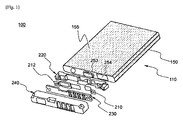
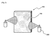
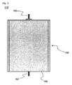
図1には、本発明の一実施形態に係る二次電池パックの分解斜視図が模式的に示されており、図2には、本発明の一実施形態に係る電池セルに保護コーティング層を形成する方式が模式的に示されている。 FIG. 1 schematically shows an exploded perspective view of a secondary battery pack according to an embodiment of the present invention, and FIG. 2 shows a protective coating layer on a battery cell according to an embodiment of the present invention. The method of forming is schematically shown.
図1及び図2を参照すると、本発明に係る二次電池パック100は、電池セル110、絶縁性装着部材220、保護回路基板230、一対の接続部材210,212、上端キャップ240、保護コーティング層155の塗布された電池ケース150などで構成されており、電池セル110の上端面に絶縁性装着部材220、接続部材210,212、保護回路基板230、及び上端キャップ240が順次に装着される。
1 and 2, the
絶縁性装着部材220には、電池セル150の電極端子253,254が露出されるように開口(図示せず)が設けられており、絶縁性装着部材220は電池セル110の上端面に直接搭載される。電池セル110の上端面への絶縁性装着部材220の結合は、接着剤によって達成されてもよい。
The insulating mounting
絶縁性上端キャップ240は、接続部材210,212と保護回路基板230が搭載された状態で、絶縁性装着部材220を覆いながら電池セル110の上端部に結合され、電池セル110の上端部の外側面を覆うことができるように所定の長さで下方に延びている。
The insulating
保護コーティング層155は、例えば、図2に示すように、絶縁性の高分子を含んでいるコーティング液を、スプレー250を用いて電池セル110の外面に噴射した後に乾燥する方式で形成することができる。
For example, as shown in FIG. 2, the
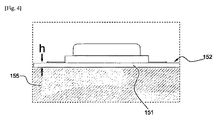
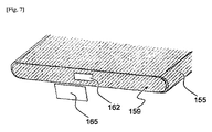
図3には、電池セルの上端部の部分斜視図が示されており、図4には、図3の部分拡大側面図が示されており、図5には、電池セルの活性化のための充電過程で用いられる接続ピンが結合されている電池セルの正面図が示されており、図6には、電池セル、保護コーティング層及び絶縁テープの分解斜視図が示されており、図7には、電池セルの下端部の部分斜視図が示されている。 3 shows a partial perspective view of the upper end portion of the battery cell, FIG. 4 shows a partially enlarged side view of FIG. 3, and FIG. 5 shows the activation of the battery cell. FIG. 6 shows an exploded perspective view of the battery cell, the protective coating layer, and the insulating tape. FIG. 1 shows a partial perspective view of the lower end portion of the battery cell.
図3乃至図7を参照すると、電池ケース150は、電池ケース150の上端外周から下方に約3mmの長さhの不コーティングマージン区間151をおいた状態で、電池ケースの全体表面に保護コーティング層(図2の155参照)が形成されている。このような不コーティングマージン区間151は、電池ケース150上に絶縁物質(図示せず)を臨時に塗布した状態でコートした後、絶縁物質を除去することによって形成する。
3 to 7, the
また、正極/分離膜/負極の構造の電極組立体が、電解液とともに、アルミニウム製の電池ケース150の内部に封止されている電池セル110を製造するために、まず、電池セル110の活性化工程のための充電ピン160,161の接続のために接続用開口区間162を電池ケース150の下端面159に形成した状態で、電池ケースの全体表面に保護コーティング層155を形成する。次いで、電池ケース150の内部に電極組立体を装着し、電池ケース150の開放上端にキャッププレート152を上方で電池セル110の外周に沿ってレーザー溶接した後(図3の矢印を参照)、キャッププレート152の電解液注入口153から電解液を注入し、電池セル活性化工程を行う。その後、電解液を補充した後、電解液注入口153を封止する。
In order to manufacture the
接続用開口区間162は、平面視で四角形の形状になっているが、その他の様々な形状にしてもよい。
The
このような接続用開口区間162は、電池ケース150の下端面の一部に絶縁物質(図示せず)を付着した状態で、保護コーティング層155を形成した後、絶縁物質を除去することによって形成する。
The
最終には、接続用開口区間162を絶縁テープである絶縁部材165で封止する。
Finally, the
電池セル活性化工程は、第1充電ピン160をキャッププレート152の上端電極端子131に接続させ、第2充電ピン161を電池ケース150の接続用開口区間162に接続させた状態で行う。
The battery cell activation process is performed in a state where the
したがって、接続用開口区間162によって第2充電ピン161の接続を容易に行うことができる。
Therefore, the second charging pin 161 can be easily connected by the
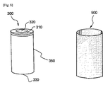
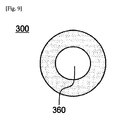
図8には、本発明の他の実施形態に係る円筒形電池セル及び保護コーティング層の分解斜視図が示されており、図9には、本発明の他の実施形態に係る円筒形電池セルの下端面が示されている。 FIG. 8 shows an exploded perspective view of a cylindrical battery cell and a protective coating layer according to another embodiment of the present invention, and FIG. 9 shows a cylindrical battery cell according to another embodiment of the present invention. The lower end surface of is shown.
図8及び図9を参照すると、円筒形電池セル300は、円筒形の電池ケース350の内部に電極組立体が電解液とともに封止されており、電池セル300の活性化工程のための充電ピン(図示せず)の接続のために接続用開口区間360を除く電池ケース350の全体表面が保護コーティング層500で被覆されている。
Referring to FIGS. 8 and 9, in the
円筒形電池セル300の上端面310には、電池ケース350と絶縁された状態で上方に突出した正極端子320が設けられており、電池セル300の下端面には負極端子330が設けられている。
A
円筒形電池セル300において、接続用開口区間360、及び電池ケース350の全体表面における保護コーティング層500の形成技術は、上述した不コーティングマージン区間(図4において151)を形成しない以外は、図1乃至図7における円筒形電池セル300と同様であり、その説明は省略するものとする。
In the
以上、本発明の実施形態に係る図面を参照して説明してきたが、本発明の属する分野における通常の知識を有する者にとっては、上記の内容に基づいて、本発明の範ちゅう内で様々な応用及び変形を行うことが可能であろう。 As described above, the description has been given with reference to the drawings according to the embodiments of the present invention. However, for those who have ordinary knowledge in the field to which the present invention belongs, there are various types within the scope of the present invention based on the above contents. Applications and variations could be made.
上述したように、本発明に係る酸化被膜の形成された電池ケースは、必要に応じて電池ケースの特定部位に接続用開口区間をおいた状態で、電池ケースの全体表面に、電気絶縁性の高分子を含んでいる保護コーティング層を形成することによって、耐久性、耐摩耗性、及び絶縁性を向上させることができる。 As described above, the battery case in which the oxide film according to the present invention is formed has an electrically insulating property on the entire surface of the battery case with a connection opening section in a specific part of the battery case as necessary. By forming a protective coating layer containing a polymer, durability, wear resistance, and insulation can be improved.
また、電池ケースの外面にラベル(Label)を貼る別途の工程が不要なため、製造過程が容易であり、実質的に同一規格において電池の容量がより向上する効果を奏する。 In addition, since a separate process of attaching a label to the outer surface of the battery case is unnecessary, the manufacturing process is easy, and the battery capacity is improved more effectively in the same standard.
100 二次電池パック
110 電池セル
150 電池ケース
151 不コーティングマージン区間
152 キャッププレート
153 電解液注入口
155 保護コーティング層
160,161 充電ピン
210,212 接続部材
220 絶縁性装着部材
230 保護回路基板
240 上端キャップ
DESCRIPTION OF
Claims (21)
前記電極組立体が内蔵されている、アルミニウム又はアルミニウム合金からなる電池ケースと、
前記電池ケースの外面の少なくとも一部に塗布されており、電気絶縁性の高分子を含んでいる保護コーティング層と、
を有していることを特徴とする、電池セル。 A positive electrode / separation membrane / negative electrode structure electrode assembly impregnated with an electrolyte and capable of charging and discharging;
A battery case made of aluminum or an aluminum alloy, in which the electrode assembly is incorporated;
Applied to at least a part of the outer surface of the battery case, and a protective coating layer containing an electrically insulating polymer;
A battery cell comprising:
Applications Claiming Priority (3)
| Application Number | Priority Date | Filing Date | Title |
|---|---|---|---|
| KR1020120012100A KR101438439B1 (en) | 2012-02-07 | 2012-02-07 | Battery Cell of Novel Embedded Type Structure |
| KR10-2012-0012100 | 2012-02-07 | ||
| PCT/KR2013/000822 WO2013119000A1 (en) | 2012-02-07 | 2013-02-01 | Embedded battery cell having novel structure |
Publications (2)
| Publication Number | Publication Date |
|---|---|
| JP2015508564A true JP2015508564A (en) | 2015-03-19 |
| JP5968464B2 JP5968464B2 (en) | 2016-08-10 |
Family
ID=48947727
Family Applications (1)
| Application Number | Title | Priority Date | Filing Date |
|---|---|---|---|
| JP2014552138A Active JP5968464B2 (en) | 2012-02-07 | 2013-02-01 | Built-in battery cell with new structure |
Country Status (7)
| Country | Link |
|---|---|
| US (1) | US9508962B2 (en) |
| EP (1) | EP2782159B1 (en) |
| JP (1) | JP5968464B2 (en) |
| KR (1) | KR101438439B1 (en) |
| CN (1) | CN103999255B (en) |
| TW (1) | TWI581486B (en) |
| WO (1) | WO2013119000A1 (en) |
Cited By (2)
| Publication number | Priority date | Publication date | Assignee | Title |
|---|---|---|---|---|
| JP2020535623A (en) * | 2017-11-17 | 2020-12-03 | 深▲セン▼市科達利実業股▲フン▼有限公司 | aluminum case |
| JP2022524390A (en) * | 2019-09-19 | 2022-05-02 | 寧徳時代新能源科技股▲分▼有限公司 | Manufacturing method of case, secondary battery, battery pack, vehicle and secondary battery |
Families Citing this family (11)
| Publication number | Priority date | Publication date | Assignee | Title |
|---|---|---|---|---|
| US9403024B2 (en) * | 2013-09-05 | 2016-08-02 | Boston Scientific Neuromodulation Corporation | Construction for an implantable medical device employing an internal support structure |
| KR101696964B1 (en) * | 2013-10-31 | 2017-01-16 | 주식회사 엘지화학 | Cylinder type secondary battery with coating layer |
| KR101779157B1 (en) * | 2015-05-26 | 2017-09-18 | 주식회사 엘지화학 | Battery module comprising a layer of pigment for radiating heat |
| KR102515095B1 (en) | 2015-11-25 | 2023-03-27 | 삼성에스디아이 주식회사 | Rechargeable battery |
| KR102594876B1 (en) * | 2018-01-11 | 2023-10-27 | 삼성전자주식회사 | Battery and electronic device using thereof |
| WO2020041375A1 (en) * | 2018-08-21 | 2020-02-27 | Richard Theodore Wurden | Batteries for electric marine propulsion systems, and associated systems and methods |
| TWI732323B (en) * | 2019-04-18 | 2021-07-01 | 新普科技股份有限公司 | Battery pack and battery pack manufacturing method |
| KR102216553B1 (en) * | 2019-06-25 | 2021-02-17 | 엘티정밀 주식회사 | Manufacturing method of battery case |
| KR102819871B1 (en) | 2020-09-04 | 2025-06-11 | 주식회사 엘지에너지솔루션 | Battery Module, and Battery Pack, and Vehicle |
| TW202438618A (en) * | 2023-02-13 | 2024-10-01 | 瑞士商亨斯邁先進材料授權(瑞士)有限公司 | Method for encapsulating electrical cells bearing a nickel-based surface |
| DE102024102377A1 (en) * | 2024-01-29 | 2025-07-31 | Bayerische Motoren Werke Aktiengesellschaft | Cylindrical battery cell and method for producing the same |
Citations (9)
| Publication number | Priority date | Publication date | Assignee | Title |
|---|---|---|---|---|
| JPH1021888A (en) * | 1996-06-28 | 1998-01-23 | Nippon Polyurethane Ind Co Ltd | Insulating battery outer can and battery using the same |
| JP2000106152A (en) * | 1998-09-30 | 2000-04-11 | Japan Storage Battery Co Ltd | Battery |
| JP2000285873A (en) * | 1999-03-31 | 2000-10-13 | Matsushita Electric Ind Co Ltd | Rechargeable battery and battery pack |
| WO2002017413A1 (en) * | 2000-08-24 | 2002-02-28 | Nok Corporation | Case for electronic parts |
| JP2002343310A (en) * | 2001-05-10 | 2002-11-29 | Showa Aluminum Kan Kk | Case for electrical equipment |
| JP2003072832A (en) * | 2001-08-31 | 2003-03-12 | Toppan Printing Co Ltd | Exterior material for lithium ion batteries |
| JP2003288866A (en) * | 2002-03-28 | 2003-10-10 | Toyo Aluminium Kk | Laminated material for secondary battery container and secondary battery container |
| JP2006324059A (en) * | 2005-05-17 | 2006-11-30 | Toyo Seikan Kaisha Ltd | Square battery container |
| US20090206096A1 (en) * | 2005-05-17 | 2009-08-20 | Toyo Seikan Kaisha, Ltd. | Three-piece square can and method of manufacturing the same |
Family Cites Families (11)
| Publication number | Priority date | Publication date | Assignee | Title |
|---|---|---|---|---|
| JP3825738B2 (en) * | 2002-10-31 | 2006-09-27 | 三洋電機株式会社 | Pack battery and manufacturing method thereof |
| KR100614367B1 (en) | 2004-10-28 | 2006-08-21 | 삼성에스디아이 주식회사 | Secondary battery |
| JP4902133B2 (en) | 2005-04-20 | 2012-03-21 | 三洋電機株式会社 | Pack battery |
| JP5142479B2 (en) * | 2006-04-18 | 2013-02-13 | 三洋電機株式会社 | Unit cell and method of manufacturing a battery pack provided with the same |
| KR100934459B1 (en) * | 2006-11-27 | 2009-12-30 | 주식회사 엘지화학 | Battery pack with excellent productivity and structural stability |
| KR20090027901A (en) * | 2007-09-13 | 2009-03-18 | 재단법인서울대학교산학협력재단 | Manufacturing Method of Lithium Secondary Battery |
| KR101001315B1 (en) * | 2007-10-18 | 2010-12-14 | 주식회사 엘지화학 | Excellent energy density secondary battery pack and PCM assembly for it |
| KR101136799B1 (en) * | 2008-04-18 | 2012-04-19 | 주식회사 엘지화학 | Slim Type Battery Pack |
| KR101137043B1 (en) * | 2009-10-13 | 2012-04-20 | 문기업 | Secondary battery packaging structure |
| KR20110053836A (en) * | 2009-11-16 | 2011-05-24 | 삼성에스디아이 주식회사 | Lithium polymer secondary battery |
| JP4803306B1 (en) * | 2010-04-07 | 2011-10-26 | ソニー株式会社 | Battery pack and battery pack manufacturing method |
-
2012
- 2012-02-07 KR KR1020120012100A patent/KR101438439B1/en active Active
-
2013
- 2013-02-01 CN CN201380004359.XA patent/CN103999255B/en active Active
- 2013-02-01 JP JP2014552138A patent/JP5968464B2/en active Active
- 2013-02-01 EP EP13746832.8A patent/EP2782159B1/en active Active
- 2013-02-01 WO PCT/KR2013/000822 patent/WO2013119000A1/en not_active Ceased
- 2013-02-04 TW TW102104212A patent/TWI581486B/en active
-
2014
- 2014-06-16 US US14/305,708 patent/US9508962B2/en active Active
Patent Citations (9)
| Publication number | Priority date | Publication date | Assignee | Title |
|---|---|---|---|---|
| JPH1021888A (en) * | 1996-06-28 | 1998-01-23 | Nippon Polyurethane Ind Co Ltd | Insulating battery outer can and battery using the same |
| JP2000106152A (en) * | 1998-09-30 | 2000-04-11 | Japan Storage Battery Co Ltd | Battery |
| JP2000285873A (en) * | 1999-03-31 | 2000-10-13 | Matsushita Electric Ind Co Ltd | Rechargeable battery and battery pack |
| WO2002017413A1 (en) * | 2000-08-24 | 2002-02-28 | Nok Corporation | Case for electronic parts |
| JP2002343310A (en) * | 2001-05-10 | 2002-11-29 | Showa Aluminum Kan Kk | Case for electrical equipment |
| JP2003072832A (en) * | 2001-08-31 | 2003-03-12 | Toppan Printing Co Ltd | Exterior material for lithium ion batteries |
| JP2003288866A (en) * | 2002-03-28 | 2003-10-10 | Toyo Aluminium Kk | Laminated material for secondary battery container and secondary battery container |
| JP2006324059A (en) * | 2005-05-17 | 2006-11-30 | Toyo Seikan Kaisha Ltd | Square battery container |
| US20090206096A1 (en) * | 2005-05-17 | 2009-08-20 | Toyo Seikan Kaisha, Ltd. | Three-piece square can and method of manufacturing the same |
Cited By (5)
| Publication number | Priority date | Publication date | Assignee | Title |
|---|---|---|---|---|
| JP2020535623A (en) * | 2017-11-17 | 2020-12-03 | 深▲セン▼市科達利実業股▲フン▼有限公司 | aluminum case |
| JP7041271B2 (en) | 2017-11-17 | 2022-03-23 | 深▲セン▼市科達利実業股▲フン▼有限公司 | aluminum case |
| JP2022524390A (en) * | 2019-09-19 | 2022-05-02 | 寧徳時代新能源科技股▲分▼有限公司 | Manufacturing method of case, secondary battery, battery pack, vehicle and secondary battery |
| JP7254953B2 (en) | 2019-09-19 | 2023-04-10 | 寧徳時代新能源科技股▲分▼有限公司 | CASE, SECONDARY BATTERY, BATTERY PACK, VEHICLE, AND SECONDARY BATTERY MANUFACTURING METHOD |
| US12224449B2 (en) | 2019-09-19 | 2025-02-11 | Contemporary Amperex Technology (Hong Kong) Limited | Case, secondary battery, battery pack, vehicle, and method for manufacturing secondary battery |
Also Published As
| Publication number | Publication date |
|---|---|
| TWI581486B (en) | 2017-05-01 |
| TW201351755A (en) | 2013-12-16 |
| KR101438439B1 (en) | 2014-09-05 |
| CN103999255B (en) | 2017-09-19 |
| EP2782159B1 (en) | 2017-10-11 |
| EP2782159A1 (en) | 2014-09-24 |
| EP2782159A4 (en) | 2014-11-12 |
| US20140329138A1 (en) | 2014-11-06 |
| US9508962B2 (en) | 2016-11-29 |
| CN103999255A (en) | 2014-08-20 |
| WO2013119000A1 (en) | 2013-08-15 |
| JP5968464B2 (en) | 2016-08-10 |
| KR20130090957A (en) | 2013-08-16 |
Similar Documents
| Publication | Publication Date | Title |
|---|---|---|
| JP5968464B2 (en) | Built-in battery cell with new structure | |
| EP3038191B1 (en) | Battery pack comprising protection circuit module case | |
| JP6053817B2 (en) | Manufacturing method of battery cell with novel structure | |
| JP5916891B2 (en) | Built-in secondary battery pack with new structure | |
| JP6068499B2 (en) | Manufacturing method of battery cell with novel structure | |
| JP4769780B2 (en) | Secondary battery | |
| JP5908116B2 (en) | Built-in battery cell with new structure | |
| KR20140099846A (en) | Battery Cell of Novel Embedded Type Structure | |
| KR101172230B1 (en) | Secondary battery and method for packing the same |
Legal Events
| Date | Code | Title | Description |
|---|---|---|---|
| A977 | Report on retrieval |
Free format text: JAPANESE INTERMEDIATE CODE: A971007 Effective date: 20150617 |
|
| A131 | Notification of reasons for refusal |
Free format text: JAPANESE INTERMEDIATE CODE: A131 Effective date: 20150622 |
|
| A521 | Request for written amendment filed |
Free format text: JAPANESE INTERMEDIATE CODE: A523 Effective date: 20150902 |
|
| A131 | Notification of reasons for refusal |
Free format text: JAPANESE INTERMEDIATE CODE: A131 Effective date: 20151005 |
|
| A521 | Request for written amendment filed |
Free format text: JAPANESE INTERMEDIATE CODE: A523 Effective date: 20151218 |
|
| TRDD | Decision of grant or rejection written | ||
| A01 | Written decision to grant a patent or to grant a registration (utility model) |
Free format text: JAPANESE INTERMEDIATE CODE: A01 Effective date: 20160606 |
|
| A61 | First payment of annual fees (during grant procedure) |
Free format text: JAPANESE INTERMEDIATE CODE: A61 Effective date: 20160705 |
|
| R150 | Certificate of patent or registration of utility model |
Ref document number: 5968464 Country of ref document: JP Free format text: JAPANESE INTERMEDIATE CODE: R150 |
|
| R250 | Receipt of annual fees |
Free format text: JAPANESE INTERMEDIATE CODE: R250 |
|
| R250 | Receipt of annual fees |
Free format text: JAPANESE INTERMEDIATE CODE: R250 |
|
| R250 | Receipt of annual fees |
Free format text: JAPANESE INTERMEDIATE CODE: R250 |
|
| S111 | Request for change of ownership or part of ownership |
Free format text: JAPANESE INTERMEDIATE CODE: R313111 |
|
| R350 | Written notification of registration of transfer |
Free format text: JAPANESE INTERMEDIATE CODE: R350 |
|
| R250 | Receipt of annual fees |
Free format text: JAPANESE INTERMEDIATE CODE: R250 |
|
| R250 | Receipt of annual fees |
Free format text: JAPANESE INTERMEDIATE CODE: R250 |
|
| R250 | Receipt of annual fees |
Free format text: JAPANESE INTERMEDIATE CODE: R250 |
|
| R250 | Receipt of annual fees |
Free format text: JAPANESE INTERMEDIATE CODE: R250 |