JP2015507575A - Method and apparatus for providing driver feedback - Google Patents
Method and apparatus for providing driver feedback Download PDFInfo
- Publication number
- JP2015507575A JP2015507575A JP2014550720A JP2014550720A JP2015507575A JP 2015507575 A JP2015507575 A JP 2015507575A JP 2014550720 A JP2014550720 A JP 2014550720A JP 2014550720 A JP2014550720 A JP 2014550720A JP 2015507575 A JP2015507575 A JP 2015507575A
- Authority
- JP
- Japan
- Prior art keywords
- vehicle
- lookup
- economic
- driving
- speed
- Prior art date
- Legal status (The legal status is an assumption and is not a legal conclusion. Google has not performed a legal analysis and makes no representation as to the accuracy of the status listed.)
- Pending
Links
- 238000000034 method Methods 0.000 title claims abstract description 38
- 238000011234 economic evaluation Methods 0.000 claims abstract description 50
- 238000011156 evaluation Methods 0.000 claims description 38
- 230000008859 change Effects 0.000 claims description 23
- 238000005259 measurement Methods 0.000 claims description 18
- 239000003607 modifier Substances 0.000 claims description 12
- 230000004044 response Effects 0.000 claims description 7
- 230000001419 dependent effect Effects 0.000 claims 1
- 230000001052 transient effect Effects 0.000 description 18
- 239000000446 fuel Substances 0.000 description 13
- 230000001133 acceleration Effects 0.000 description 10
- 230000006870 function Effects 0.000 description 4
- 238000010586 diagram Methods 0.000 description 3
- 238000002485 combustion reaction Methods 0.000 description 2
- 238000012545 processing Methods 0.000 description 2
- 238000012360 testing method Methods 0.000 description 2
- 238000012546 transfer Methods 0.000 description 2
- 230000000007 visual effect Effects 0.000 description 2
- 102100021283 1-aminocyclopropane-1-carboxylate synthase-like protein 1 Human genes 0.000 description 1
- 101000675558 Homo sapiens 1-aminocyclopropane-1-carboxylate synthase-like protein 1 Proteins 0.000 description 1
- 230000003044 adaptive effect Effects 0.000 description 1
- 238000013459 approach Methods 0.000 description 1
- 230000005540 biological transmission Effects 0.000 description 1
- 238000004364 calculation method Methods 0.000 description 1
- 238000004891 communication Methods 0.000 description 1
- 230000000694 effects Effects 0.000 description 1
- 239000004973 liquid crystal related substance Substances 0.000 description 1
- 230000007774 longterm Effects 0.000 description 1
- 238000012986 modification Methods 0.000 description 1
- 230000004048 modification Effects 0.000 description 1
- 230000007935 neutral effect Effects 0.000 description 1
- 230000001737 promoting effect Effects 0.000 description 1
- 230000009467 reduction Effects 0.000 description 1
- 230000008439 repair process Effects 0.000 description 1
Images


Classifications
-
- B—PERFORMING OPERATIONS; TRANSPORTING
- B60—VEHICLES IN GENERAL
- B60W—CONJOINT CONTROL OF VEHICLE SUB-UNITS OF DIFFERENT TYPE OR DIFFERENT FUNCTION; CONTROL SYSTEMS SPECIALLY ADAPTED FOR HYBRID VEHICLES; ROAD VEHICLE DRIVE CONTROL SYSTEMS FOR PURPOSES NOT RELATED TO THE CONTROL OF A PARTICULAR SUB-UNIT
- B60W50/00—Details of control systems for road vehicle drive control not related to the control of a particular sub-unit, e.g. process diagnostic or vehicle driver interfaces
- B60W50/08—Interaction between the driver and the control system
- B60W50/14—Means for informing the driver, warning the driver or prompting a driver intervention
-
- G—PHYSICS
- G07—CHECKING-DEVICES
- G07C—TIME OR ATTENDANCE REGISTERS; REGISTERING OR INDICATING THE WORKING OF MACHINES; GENERATING RANDOM NUMBERS; VOTING OR LOTTERY APPARATUS; ARRANGEMENTS, SYSTEMS OR APPARATUS FOR CHECKING NOT PROVIDED FOR ELSEWHERE
- G07C5/00—Registering or indicating the working of vehicles
- G07C5/08—Registering or indicating performance data other than driving, working, idle, or waiting time, with or without registering driving, working, idle or waiting time
- G07C5/0841—Registering performance data
- G07C5/085—Registering performance data using electronic data carriers
-
- B60K35/28—
-
- B—PERFORMING OPERATIONS; TRANSPORTING
- B60—VEHICLES IN GENERAL
- B60R—VEHICLES, VEHICLE FITTINGS, OR VEHICLE PARTS, NOT OTHERWISE PROVIDED FOR
- B60R16/00—Electric or fluid circuits specially adapted for vehicles and not otherwise provided for; Arrangement of elements of electric or fluid circuits specially adapted for vehicles and not otherwise provided for
- B60R16/02—Electric or fluid circuits specially adapted for vehicles and not otherwise provided for; Arrangement of elements of electric or fluid circuits specially adapted for vehicles and not otherwise provided for electric constitutive elements
- B60R16/023—Electric or fluid circuits specially adapted for vehicles and not otherwise provided for; Arrangement of elements of electric or fluid circuits specially adapted for vehicles and not otherwise provided for electric constitutive elements for transmission of signals between vehicle parts or subsystems
- B60R16/0231—Circuits relating to the driving or the functioning of the vehicle
- B60R16/0236—Circuits relating to the driving or the functioning of the vehicle for economical driving
-
- B—PERFORMING OPERATIONS; TRANSPORTING
- B60—VEHICLES IN GENERAL
- B60W—CONJOINT CONTROL OF VEHICLE SUB-UNITS OF DIFFERENT TYPE OR DIFFERENT FUNCTION; CONTROL SYSTEMS SPECIALLY ADAPTED FOR HYBRID VEHICLES; ROAD VEHICLE DRIVE CONTROL SYSTEMS FOR PURPOSES NOT RELATED TO THE CONTROL OF A PARTICULAR SUB-UNIT
- B60W30/00—Purposes of road vehicle drive control systems not related to the control of a particular sub-unit, e.g. of systems using conjoint control of vehicle sub-units, or advanced driver assistance systems for ensuring comfort, stability and safety or drive control systems for propelling or retarding the vehicle
- B60W30/18—Propelling the vehicle
- B60W30/182—Selecting between different operative modes, e.g. comfort and performance modes
-
- B—PERFORMING OPERATIONS; TRANSPORTING
- B60—VEHICLES IN GENERAL
- B60W—CONJOINT CONTROL OF VEHICLE SUB-UNITS OF DIFFERENT TYPE OR DIFFERENT FUNCTION; CONTROL SYSTEMS SPECIALLY ADAPTED FOR HYBRID VEHICLES; ROAD VEHICLE DRIVE CONTROL SYSTEMS FOR PURPOSES NOT RELATED TO THE CONTROL OF A PARTICULAR SUB-UNIT
- B60W50/00—Details of control systems for road vehicle drive control not related to the control of a particular sub-unit, e.g. process diagnostic or vehicle driver interfaces
-
- G—PHYSICS
- G07—CHECKING-DEVICES
- G07C—TIME OR ATTENDANCE REGISTERS; REGISTERING OR INDICATING THE WORKING OF MACHINES; GENERATING RANDOM NUMBERS; VOTING OR LOTTERY APPARATUS; ARRANGEMENTS, SYSTEMS OR APPARATUS FOR CHECKING NOT PROVIDED FOR ELSEWHERE
- G07C5/00—Registering or indicating the working of vehicles
- G07C5/004—Indicating the operating range of the engine
-
- G—PHYSICS
- G07—CHECKING-DEVICES
- G07C—TIME OR ATTENDANCE REGISTERS; REGISTERING OR INDICATING THE WORKING OF MACHINES; GENERATING RANDOM NUMBERS; VOTING OR LOTTERY APPARATUS; ARRANGEMENTS, SYSTEMS OR APPARATUS FOR CHECKING NOT PROVIDED FOR ELSEWHERE
- G07C5/00—Registering or indicating the working of vehicles
- G07C5/08—Registering or indicating performance data other than driving, working, idle, or waiting time, with or without registering driving, working, idle or waiting time
- G07C5/0808—Diagnosing performance data
-
- G—PHYSICS
- G07—CHECKING-DEVICES
- G07C—TIME OR ATTENDANCE REGISTERS; REGISTERING OR INDICATING THE WORKING OF MACHINES; GENERATING RANDOM NUMBERS; VOTING OR LOTTERY APPARATUS; ARRANGEMENTS, SYSTEMS OR APPARATUS FOR CHECKING NOT PROVIDED FOR ELSEWHERE
- G07C5/00—Registering or indicating the working of vehicles
- G07C5/08—Registering or indicating performance data other than driving, working, idle, or waiting time, with or without registering driving, working, idle or waiting time
- G07C5/0816—Indicating performance data, e.g. occurrence of a malfunction
-
- G—PHYSICS
- G09—EDUCATION; CRYPTOGRAPHY; DISPLAY; ADVERTISING; SEALS
- G09B—EDUCATIONAL OR DEMONSTRATION APPLIANCES; APPLIANCES FOR TEACHING, OR COMMUNICATING WITH, THE BLIND, DEAF OR MUTE; MODELS; PLANETARIA; GLOBES; MAPS; DIAGRAMS
- G09B9/00—Simulators for teaching or training purposes
- G09B9/02—Simulators for teaching or training purposes for teaching control of vehicles or other craft
- G09B9/04—Simulators for teaching or training purposes for teaching control of vehicles or other craft for teaching control of land vehicles
- G09B9/052—Simulators for teaching or training purposes for teaching control of vehicles or other craft for teaching control of land vehicles characterised by provision for recording or measuring trainee's performance
-
- B60K2360/174—
-
- B—PERFORMING OPERATIONS; TRANSPORTING
- B60—VEHICLES IN GENERAL
- B60W—CONJOINT CONTROL OF VEHICLE SUB-UNITS OF DIFFERENT TYPE OR DIFFERENT FUNCTION; CONTROL SYSTEMS SPECIALLY ADAPTED FOR HYBRID VEHICLES; ROAD VEHICLE DRIVE CONTROL SYSTEMS FOR PURPOSES NOT RELATED TO THE CONTROL OF A PARTICULAR SUB-UNIT
- B60W50/00—Details of control systems for road vehicle drive control not related to the control of a particular sub-unit, e.g. process diagnostic or vehicle driver interfaces
- B60W2050/0062—Adapting control system settings
- B60W2050/0075—Automatic parameter input, automatic initialising or calibrating means
- B60W2050/0095—Automatic control mode change
-
- B—PERFORMING OPERATIONS; TRANSPORTING
- B60—VEHICLES IN GENERAL
- B60W—CONJOINT CONTROL OF VEHICLE SUB-UNITS OF DIFFERENT TYPE OR DIFFERENT FUNCTION; CONTROL SYSTEMS SPECIALLY ADAPTED FOR HYBRID VEHICLES; ROAD VEHICLE DRIVE CONTROL SYSTEMS FOR PURPOSES NOT RELATED TO THE CONTROL OF A PARTICULAR SUB-UNIT
- B60W50/00—Details of control systems for road vehicle drive control not related to the control of a particular sub-unit, e.g. process diagnostic or vehicle driver interfaces
- B60W50/08—Interaction between the driver and the control system
- B60W50/14—Means for informing the driver, warning the driver or prompting a driver intervention
- B60W2050/146—Display means
-
- B—PERFORMING OPERATIONS; TRANSPORTING
- B60—VEHICLES IN GENERAL
- B60W—CONJOINT CONTROL OF VEHICLE SUB-UNITS OF DIFFERENT TYPE OR DIFFERENT FUNCTION; CONTROL SYSTEMS SPECIALLY ADAPTED FOR HYBRID VEHICLES; ROAD VEHICLE DRIVE CONTROL SYSTEMS FOR PURPOSES NOT RELATED TO THE CONTROL OF A PARTICULAR SUB-UNIT
- B60W2510/00—Input parameters relating to a particular sub-units
- B60W2510/06—Combustion engines, Gas turbines
- B60W2510/0638—Engine speed
-
- B—PERFORMING OPERATIONS; TRANSPORTING
- B60—VEHICLES IN GENERAL
- B60W—CONJOINT CONTROL OF VEHICLE SUB-UNITS OF DIFFERENT TYPE OR DIFFERENT FUNCTION; CONTROL SYSTEMS SPECIALLY ADAPTED FOR HYBRID VEHICLES; ROAD VEHICLE DRIVE CONTROL SYSTEMS FOR PURPOSES NOT RELATED TO THE CONTROL OF A PARTICULAR SUB-UNIT
- B60W2510/00—Input parameters relating to a particular sub-units
- B60W2510/18—Braking system
-
- B—PERFORMING OPERATIONS; TRANSPORTING
- B60—VEHICLES IN GENERAL
- B60W—CONJOINT CONTROL OF VEHICLE SUB-UNITS OF DIFFERENT TYPE OR DIFFERENT FUNCTION; CONTROL SYSTEMS SPECIALLY ADAPTED FOR HYBRID VEHICLES; ROAD VEHICLE DRIVE CONTROL SYSTEMS FOR PURPOSES NOT RELATED TO THE CONTROL OF A PARTICULAR SUB-UNIT
- B60W2520/00—Input parameters relating to overall vehicle dynamics
- B60W2520/10—Longitudinal speed
-
- B—PERFORMING OPERATIONS; TRANSPORTING
- B60—VEHICLES IN GENERAL
- B60W—CONJOINT CONTROL OF VEHICLE SUB-UNITS OF DIFFERENT TYPE OR DIFFERENT FUNCTION; CONTROL SYSTEMS SPECIALLY ADAPTED FOR HYBRID VEHICLES; ROAD VEHICLE DRIVE CONTROL SYSTEMS FOR PURPOSES NOT RELATED TO THE CONTROL OF A PARTICULAR SUB-UNIT
- B60W2540/00—Input parameters relating to occupants
- B60W2540/30—Driving style
-
- Y—GENERAL TAGGING OF NEW TECHNOLOGICAL DEVELOPMENTS; GENERAL TAGGING OF CROSS-SECTIONAL TECHNOLOGIES SPANNING OVER SEVERAL SECTIONS OF THE IPC; TECHNICAL SUBJECTS COVERED BY FORMER USPC CROSS-REFERENCE ART COLLECTIONS [XRACs] AND DIGESTS
- Y02—TECHNOLOGIES OR APPLICATIONS FOR MITIGATION OR ADAPTATION AGAINST CLIMATE CHANGE
- Y02T—CLIMATE CHANGE MITIGATION TECHNOLOGIES RELATED TO TRANSPORTATION
- Y02T10/00—Road transport of goods or passengers
- Y02T10/80—Technologies aiming to reduce greenhouse gasses emissions common to all road transportation technologies
- Y02T10/84—Data processing systems or methods, management, administration
Abstract
本発明は自動車の少なくとも1の運転パラメータを評価する方法に関する。自動車の運転パラメータに関するシステム変数が測定される。運転パラメータと関連するルックアップマップ(A;S;B)がアクセスされる。ルックアップマップ(A;S;B)は、閾値(R0,R1,R2,R3,R4)の1又は複数のセットを備えており、比較が測定されたシステム変数と閾値(R0,R1,R2,R3,R4)との間で行われる。運転者にフィードバックを提供するために、経済性評価(E1,E2,E3,E4,E5)が、ルックアップマップと経済性評価(E1,E2,E3,E4,E5)に基づく指標出力とから取得される。本発明はまた、運転者のフィードバックを提供するための装置に関する。The present invention relates to a method for evaluating at least one driving parameter of a motor vehicle. System variables relating to the driving parameters of the vehicle are measured. A lookup map (A; S; B) associated with the operating parameters is accessed. The lookup map (A; S; B) comprises one or more sets of thresholds (R0, R1, R2, R3, R4), and the system variables and thresholds (R0, R1, R2) for which the comparison was measured. , R3, R4). To provide feedback to the driver, the economic evaluation (E1, E2, E3, E4, E5) is derived from the look-up map and the indicator output based on the economic evaluation (E1, E2, E3, E4, E5) To be acquired. The invention also relates to an apparatus for providing driver feedback.
Description
本発明は、自動車の運転パラメータに基づいて運転者のフィードバックを提供するための方法に関する。また、本発明は、運転者のフィードバックを提供するための装置に関する。本発明の側面は、装置、方法及び車両(自動車)に関する。 The present invention relates to a method for providing driver feedback based on driving parameters of an automobile. The invention also relates to an apparatus for providing driver feedback. Aspects of the present invention relate to an apparatus, a method, and a vehicle (automobile).
自動車の現在の走行状態を視覚化するグラフィック表示を生成するために、米国特許出願公開第2011/0148614号明細書が知られている。経済性指標は、アクセルペダル位置、エンジン回転数、車両速度及び接続ギヤに基づくアルゴリズムによって表示されるために生成される。燃料消費量に関して最適化された走行状態が緑の濃淡で表示され、最適化されていない走行状態が黄色又は赤の濃淡で表示される。経済性指標が主要な車両パラメータに基づく評価(格付け)を提供する一方で、故障が無いことが、運転者に対し、経済性を向上させるために彼らがどのようなドライビングスタイルに変更すべきか判断することを困難にし得る。更には、複数の性能パラメータへの依存が、計算要件を増加させている。 U.S. Patent Application Publication No. 2011/0148614 is known for generating a graphic display that visualizes the current driving state of a motor vehicle. The economic index is generated for display by an algorithm based on accelerator pedal position, engine speed, vehicle speed and connected gear. The driving state that is optimized with respect to the fuel consumption is displayed in green shades, and the driving state that is not optimized is displayed in yellow or red shades. While the economics index provides an assessment (rating) based on key vehicle parameters, the absence of a failure determines for the driver what driving style they should change to improve economy Can be difficult to do. Furthermore, the dependence on multiple performance parameters increases the computational requirements.
また、独国特許出願公開第102010018826号明細書は、車両速度、スロットルペダル位置及びブレーキペダル位置等のような異なる運転パラメータに基づく運転者フィードバックシステムを開示している。実際の運転パラメータは、運転者が彼らのドライビングスタイルを調整することができるように理想的な目標値と並べて表示される。理想的な目標値が、任意の与えられた運転条件に対し、どのように決定されたかについては、示唆がされていない。
本発明は、従来のシステムに関連する問題又は欠点の少なくともいくつかを克服又は改善するために提示されるものである。 The present invention is presented to overcome or ameliorate at least some of the problems or disadvantages associated with conventional systems.
本発明は一側面において、自動車の少なくとも1の運転パラメータを評価して運転者のフィードバックを提供する方法であって、自動車の第1の運転パラメータに関する第1のシステム変数を測定することと、第1の運転パラメータと関連する第1のルックアップマップにアクセスすることであって、第1のルックアップマップが第1の閾値の1又は複数のセットを備えていることと、第1のシステム変数を第1の閾値と比較して第1の経済性評価を決定することと、第1の経済性評価に基づいて第1の経済性指標を出力することを備える方法を提供する。 In one aspect, the present invention is a method for evaluating at least one driving parameter of a vehicle to provide driver feedback, measuring a first system variable related to the first driving parameter of the vehicle, Accessing a first lookup map associated with one operating parameter, the first lookup map comprising one or more sets of first thresholds, and a first system variable To a first threshold value to determine a first economic evaluation and to output a first economic index based on the first economic evaluation.
ルックアップマップに保存された予め定められた閾値を有する測定されたシステム変数の比較は、車両燃料消費量の指標を提供することができる。よって、第1の経済性指標は、運転者にフィードバックを提供することができる。閾値は、特定の運転条件(車両速度など)に適合させることができ、これにより運転者へのフィードバックの精度を向上させることができる。よって、第1の経済性指標の出力は、運転者が、燃料経済性を改善するために彼らのドライビングスタイルを適用することの助けとなり得るものである。 Comparison of measured system variables with a predetermined threshold stored in a lookup map can provide an indication of vehicle fuel consumption. Thus, the first economic index can provide feedback to the driver. The threshold can be adapted to specific driving conditions (such as vehicle speed), thereby improving the accuracy of feedback to the driver. Thus, the output of the first economic index can help drivers apply their driving style to improve fuel economy.
第1の経済性指標は、運転手が自動車を運転する際に運転者に対してフィードバックを提供するために実質的にリアルタイムで生成することができる。代替的に又は付加的には、平均経済性評価が、例えば、特定の旅程又は期間に渡り平均化された第1の経済性指標を出力するために算出することができる。第1の経済性指標は、音声又は視覚出力であり得る。第1の経済性指標は、例えば、1(1)から5(5)の範囲の経済性の指数又はスコアの形態をとり得るであろう。第1の経済性指標のグラフィカル表現を提供することができる。 The first economic indicator can be generated substantially in real time to provide feedback to the driver as the driver drives the vehicle. Alternatively or additionally, an average economic rating can be calculated, for example, to output a first economic measure averaged over a particular itinerary or period. The first economic indicator may be audio or visual output. The first economic index could take the form of, for example, an economic index or score ranging from 1 (1) to 5 (5). A graphical representation of the first economic index can be provided.
方法は、複数のルックアップマップから第1のルックアップマップを選択することであって、複数のルックアップマップのそれぞれが車両運転モードのそれぞれと関連していることを含むことができる。方法は、車両モードデータを受け付け、受け付けた車両モードデータに依存する車両運転モードを決定し、決定された車両運転モードに依存する複数のルックアップマップから第1のルックアップマップにアクセスすることを含むことができる。 The method can include selecting a first lookup map from a plurality of lookup maps, each of the plurality of lookup maps being associated with a respective vehicle driving mode. The method accepts vehicle mode data, determines a vehicle driving mode that depends on the received vehicle mode data, and accesses the first lookup map from a plurality of lookup maps that depend on the determined vehicle driving mode. Can be included.
第1のルックアップマップは、第1の閾値の複数のセットを備え、それぞれのセットが特定の車両運転条件に関連する。第1の閾値のそれぞれのセットが車両速度の予め定められた範囲と関連し、方法が、自動車の速度を決定し、決定された車両速度に依存する第1のシステム変数との比較のために第1のルックアップマップの第1の閾値のセットを選択する。 The first lookup map comprises a plurality of sets of first thresholds, each set associated with a particular vehicle driving condition. Each set of first threshold values is associated with a predetermined range of vehicle speeds, and the method determines the speed of the vehicle for comparison with a first system variable that depends on the determined vehicle speed. Select a first set of thresholds for the first lookup map.
第1の閾値が、自動車の第1のシステム変数の定常状態の測定に対応するか又は第1の閾値が自動車の第1のシステム変数の変化率の測定に対応する。 The first threshold corresponds to a steady state measurement of the first system variable of the vehicle, or the first threshold corresponds to a measurement of the rate of change of the first system variable of the vehicle.
方法は、第1の運転パラメータと関連する複数のルックアップマップから第1のルックアップマップを選択することを含み、その選択が、測定された第1のシステム変数の特性に基づいて実行されることを含む。 The method includes selecting a first lookup map from a plurality of lookup maps associated with a first operating parameter, the selection being performed based on measured characteristics of the first system variable. Including that.
方法は、第1の経済性指標を生成するために、修飾子を第1の経済性評価に適用することを含む。修飾子が、自動車の第2運転パラメータに関する第2のシステム変数に基づくことができる。 The method includes applying a qualifier to the first economic evaluation to generate a first economic index. The modifier may be based on a second system variable related to the second driving parameter of the vehicle.
少なくとも1の運転パラメータが、1又は複数の以下のもの:スロットル位置、エンジン回転数、車両速度、及び摩擦ブレーキ、に関し得る。 At least one operating parameter may relate to one or more of the following: throttle position, engine speed, vehicle speed, and friction brake.
方法は、自動車の異なる運転パラメータに関する少なくとも1の追加システム変数に対して測定、アクセス、比較及び出力するステップを繰り返すことを含み得る。方法は、少なくとも1の追加システム変数に対して決定された経済性評価に基づく少なくとも1の追加的な指標を出力することを含み得る。 The method may include repeating the steps of measuring, accessing, comparing and outputting for at least one additional system variable for different driving parameters of the vehicle. The method may include outputting at least one additional indicator based on the economic evaluation determined for the at least one additional system variable.
ルックアップマップは、例えば、一連の閾値範囲(又は帯域)を含む(からなる)ことができる。第1の経済性評価は、測定された第1のシステム変数が位置する閾値範囲に基づくことができる。第1の経済性指標は、第1の経済性評価に対応することができる。 The lookup map can include (consist of) a series of threshold ranges (or bands), for example. The first economic evaluation can be based on a threshold range in which the measured first system variable is located. The first economic index can correspond to the first economic evaluation.
任意には、修飾子は、ルックアップマップから決定された第1の経済性評価に適用することができる。修飾子は、例えば、自動車の第2運転パラメータに関する第2のシステム変数に基づくことができる。一例として、第1のシステム変数は、エンジン回転数とすることができ、修飾子は、自動車への空力荷重を考慮するために車両速度に関連することができる。第1の経済性評価は、車両速度が高い場合に低い経済性を表すように補正され得る。修飾子は、別々のルックアップマップから導出することが想定されるであろう。 Optionally, the modifier can be applied to a first economic evaluation determined from a lookup map. The modifier can be based, for example, on a second system variable relating to a second driving parameter of the vehicle. As an example, the first system variable can be engine speed and the modifier can be related to vehicle speed to account for aerodynamic loads on the vehicle. The first economic rating can be corrected to represent low economics when the vehicle speed is high. It will be assumed that the modifier is derived from a separate lookup map.
第1のルックアップマップは、第1の閾値の複数のセットを含む(からなる)ことができる。分析に用いられる閾値のセットは、車両運転パラメータ及び/又は車両走行モードに基づいて選択されることができる。例えば、(比較されるシステム変数に対する)第1の閾値のセットは、1又は複数の下記:車両速度、エンジン回転数、及び接続ギヤ、に基づいて選択できる。 The first lookup map can include (consist of) a plurality of sets of first thresholds. The set of thresholds used for the analysis can be selected based on vehicle driving parameters and / or vehicle driving modes. For example, the first set of thresholds (for the system variables being compared) can be selected based on one or more of the following: vehicle speed, engine speed, and connected gear.
第1の閾値は、自動車の第1の運転パラメータの定常状態の測定に対応することができる。例えば、測定された運転パラメータは、一定期間にわたって平均化することができる。代替的には、第1の閾値は、自動車の第1の運転パラメータの変化率の測定に対応することができる。それにより得られた測定された運転パラメータは、過渡的(一過性)であり、正(測定期間に渡って増加を示す)又は負(測定機関にわたって減少を示す)であり得る。 The first threshold can correspond to a steady state measurement of the first driving parameter of the vehicle. For example, measured operating parameters can be averaged over a period of time. Alternatively, the first threshold can correspond to a measurement of the rate of change of the first driving parameter of the vehicle. The measured operational parameters thereby obtained are transient (transient) and can be positive (indicating an increase over the measurement period) or negative (indicating a decrease over the measuring engine).
方法は、例えば測定された第1のシステム変数を補間ルックアップマップに参照することにより、第1のシステム変数を正規化(標準化)することを更に含むことができる。正規化された第1のシステム変数は、特定の車両/エンジンタイプ又は構成とは依存しないようにすることができる。正規化された第1のシステム変数は、第1のシステム変数に関する第1の経済性評価を決定するために、第1の閾値と比較することができる。 The method can further include normalizing (normalizing) the first system variable, eg, by referring to the measured first system variable in an interpolated lookup map. The normalized first system variable may be independent of a particular vehicle / engine type or configuration. The normalized first system variable can be compared to a first threshold to determine a first economic rating for the first system variable.
方法は、第1の運転パラメータと関連する複数のルックアップマップから第1のルックアップマップを選択するステップを含むことができる。このアプローチは、現在の運転条件/パラメータを反映させるためにルックアップマップのダイナミック(動的)な選択を提供するものである。その選択は、測定された第1のシステム変数の特性(例えば、正又は負)又は値に基づいて実行されることができる。例えば、定常状態ルックアップマップは、定常状態の測定が行われる場合に選択できる。同様に、正又は負の過渡ルックアップマップが、正又は負の速度変化のそれぞれの測定に関して選択できる。代替的には、ルックアップマップは、現在の車両走行モード又は現在のギア選択に基づいて選択できる。 The method can include selecting a first lookup map from a plurality of lookup maps associated with the first operating parameter. This approach provides a dynamic selection of a lookup map to reflect current operating conditions / parameters. The selection can be performed based on a measured characteristic (eg, positive or negative) or value of the first system variable. For example, a steady state lookup map can be selected when a steady state measurement is made. Similarly, a positive or negative transient lookup map can be selected for each measurement of positive or negative speed change. Alternatively, the lookup map can be selected based on the current vehicle driving mode or the current gear selection.
自動車の異なる運転パラメータに関する少なくとも1の追加システム変数に対し、本発明のステップ(a)から(d)を繰り返し可能であることが理解されるであろう。少なくとも1の追加的な経済性指標が、少なくとも1の追加システム変数に対して決定された第2の指標に基づいて出力できる。したがって、車両操作の異なる側面に対して指標を提供するために、複数の経済性指標が出力できることを理解すべきであろう。3つの経済性指標(アクセル、スピードとエンジンの組み合わせ及びブレーキ)が運転者に有用な情報を提供することが想定される。 It will be appreciated that steps (a) to (d) of the present invention can be repeated for at least one additional system variable for different driving parameters of the vehicle. At least one additional economic indicator can be output based on the second indicator determined for the at least one additional system variable. Thus, it should be understood that multiple economic indicators can be output to provide indicators for different aspects of vehicle operation. It is envisioned that three economic indicators (accelerator, speed / engine combination and brakes) provide useful information to the driver.
システム変数は、自動車の通信バスから抽出できる。よって、システム変数は、自動車への運転手入力の直接測定を提供することができる。測定されたシステム変数は、1又は複数の下記:スロットルペダル位置及び/又は等価トルク要求、ブレーキペダル位置、エンジン回転数、車両速度、エンジンブレーキを介した加速又は減速、及び摩擦ブレーキ、に関連することができる。 System variables can be extracted from the vehicle communication bus. Thus, system variables can provide a direct measure of driver input to the vehicle. The measured system variables relate to one or more of the following: throttle pedal position and / or equivalent torque demand, brake pedal position, engine speed, vehicle speed, acceleration or deceleration via engine brake, and friction brake. be able to.
本発明に係る方法は、ある予め定められた(所定の)条件下において抑制することができる。例えば、クルーズコントロール又はヒルディセンデント制御が自動車に接続されている場合に、運転者のフィードバックを抑制することができる。 The method according to the invention can be suppressed under certain predetermined (predetermined) conditions. For example, the driver's feedback can be suppressed when cruise control or hill-discent control is connected to an automobile.
本発明は更なる一側面において、自動車の少なくとも1の運転パラメータの評価に応じて運転者のフィードバックを提供するための装置であって、自動車の第1の運転パラメータに関する第1のシステム変数に対応するセンサデータを受け付けるためのデータバスと、第1の運転パラメータと関連する第1のルックアップマップを記憶するための記憶装置であって、第1のルックアップマップが第1の閾値の少なくとも1のセットを備えており、センサデータを第1の閾値のセットと比較し、第1の経済性評価を決定するように構成されたプロセッサと、第1の経済性評価に基づいて第1の経済性指標を出力するための出力装置とを備える装置が提供される。 In a further aspect, the invention provides an apparatus for providing driver feedback in response to an evaluation of at least one driving parameter of a vehicle, corresponding to a first system variable relating to the first driving parameter of the vehicle. And a storage device for storing a first lookup map associated with the first operating parameter, wherein the first lookup map is at least one of the first threshold values. And a processor configured to compare the sensor data with a first set of thresholds to determine a first economic rating, and a first economy based on the first economic rating And an output device for outputting the sex indicator.
記憶装置が、複数のルックアップマップを記憶し、複数のルックアップマップのそれぞれが車両運転モードのそれぞれと関連しており、プロセッサが、複数のルックアップマップからのセンサデータとの比較のために第1のルックアップマップを選択するように構成されている。 A storage device stores a plurality of lookup maps, each of the plurality of lookup maps being associated with each of the vehicle driving modes, and the processor for comparison with sensor data from the plurality of lookup maps. A first lookup map is configured to be selected.
プロセッサが、車両運転モードデータを受け付け、車両運転モードデータの受け付けに応答して車両運転モードを決定し、決定された車両運転モードに依存する複数のルックアップマップから第1のルックアップマップを選択するように構成されることができる。 A processor receives vehicle driving mode data, determines a vehicle driving mode in response to receiving the vehicle driving mode data, and selects a first lookup map from a plurality of lookup maps depending on the determined vehicle driving mode. Can be configured to.
第1のルックアップマップが第1の閾値の複数のセットを備え、それぞれのセットが特定の車両運転条件に関連することができる。第1の閾値のそれぞれのセットが車両速度の予め定められた範囲と関連し、プロセッサが自動車の速度を決定し、決定された車両速度に依存する第1のシステム変数との比較のために第1のルックアップマップの第1の閾値のセットを選択するように構成されることができる。 The first lookup map may comprise a plurality of sets of first thresholds, each set being associated with a particular vehicle operating condition. Each set of first threshold values is associated with a predetermined range of vehicle speeds, and the processor determines the speed of the vehicle and sets the first value for comparison with a first system variable that depends on the determined vehicle speed. A first threshold set of one lookup map may be configured to be selected.
第1の閾値が自動車の第1のシステム変数の定常状態の測定に対応するか又は第1の閾値が自動車の第1のシステム変数の変化率の測定に対応することができる。 The first threshold may correspond to a steady state measurement of the first system variable of the vehicle or the first threshold may correspond to a measurement of the rate of change of the first system variable of the vehicle.
データバスが自動車の複数の運転パラメータに関するセンサデータを受け付けるように構成され、プロセッサが各運転パラメータに関するセンサデータを、それぞれの経済性評価を決定するために記憶装置に記憶された閾値のそれぞれのセットと比較するように構成されることができる。 A data bus is configured to accept sensor data relating to a plurality of driving parameters of the vehicle, and a processor sets sensor data relating to each driving parameter to a respective set of threshold values stored in a storage device to determine a respective economic evaluation. Can be configured to compare with.
プロセッサが、第1の経済性指標を生成するために修飾子を第1の経済性評価に適用するように構成されることができる。修飾子が、自動車の第2運転パラメータに関する第2のシステム変数に基づくことができる。 The processor can be configured to apply a qualifier to the first economic evaluation to generate a first economic indicator. The modifier may be based on a second system variable related to the second driving parameter of the vehicle.
少なくとも1の運転パラメータが1又は複数の下記:スロットル位置、エンジン回転数、車両速度、及び摩擦ブレーキ、に関連することができる。 At least one operating parameter may relate to one or more of the following: throttle position, engine speed, vehicle speed, and friction brake.
本発明は他の側面において、上述した運転者のフィードバックを提供するための装置を有する自動車に関する。 In another aspect, the invention relates to a motor vehicle having an apparatus for providing driver feedback as described above.
データバスは、自動車の種々のセンサからデータを受け付けることができる。例えば、データバスは、1又は複数の下記のデータタイプ:エンジン回転数データ、車両速度データ、ブレーキスイッチステータスデータ、(ブレーキシリンダで測定された)ブレーキ圧、(アクセルペダル位置から導出された)バーチャルペダル位置、トランスミッションステータス、トランスファーケースステータス、地形モード、地形モード要求信号、クルーズコントロールステータス、及びヒルディセンデントステータス、を受け付けることができる。 The data bus can accept data from various sensors of the automobile. For example, the data bus may be one or more of the following data types: engine speed data, vehicle speed data, brake switch status data, brake pressure (measured at the brake cylinder), virtual (derived from accelerator pedal position) The pedal position, transmission status, transfer case status, terrain mode, terrain mode request signal, cruise control status, and hill descendent status can be received.
プロセッサは、第1のシステム変数に基づく第1のルックアップマップにアクセスすることによって、第1の経済性評価を決定するように構成できる。任意には、プロセッサは、修飾子を第1の経済性評価に適用するように構成できる。修飾子は、例えば、自動車の第2運転パラメータに関する第2のシステム変数に基づくことができる。プロセッサは、第2のシステム変数に基づく修飾子を決定するために第2のルックアップマップにアクセスすることができる。 The processor can be configured to determine a first economic valuation by accessing a first lookup map based on a first system variable. Optionally, the processor can be configured to apply the modifier to the first economic evaluation. The modifier can be based, for example, on a second system variable relating to a second driving parameter of the vehicle. The processor can access the second lookup map to determine a qualifier based on the second system variable.
第1の閾値は、自動車の第1の運転パラメータの定常状態の測定に対応することができる。代替的には、第1の閾値は、自動車の第1の運転パラメータ(例えば、第1の運転パラメータの測定された変化率)の過渡測定に対応することができる。 The first threshold can correspond to a steady state measurement of the first driving parameter of the vehicle. Alternatively, the first threshold can correspond to a transient measurement of the first driving parameter of the vehicle (eg, the measured rate of change of the first driving parameter).
データバスは、自動車の複数の運転パラメータに関するセンサデータを受け付けるように構成することができる。プロセッサは、それぞれの経済性評価を決定するために記憶装置に記憶された閾値データのそれぞれのセットと各運転パラメータに関するセンサデータを比較するように構成される。例えば、プロセッサは、1又は複数の下記ルックアップマップ;定常状態、正の過渡、及び負の過渡、にアクセスすることができる。 The data bus can be configured to accept sensor data relating to a plurality of driving parameters of the vehicle. The processor is configured to compare the sensor data for each operating parameter with a respective set of threshold data stored in a storage device to determine a respective economic evaluation. For example, the processor can access one or more of the following lookup maps: steady state, positive transients, and negative transients.
第1のルックアップマップは、ハイブリッド、クルーズコントロール、地形応答、ダイナミック、及びデフォルト等の車両運転モードに関する第1の閾値のセットを備えることができる。 The first lookup map may comprise a first set of thresholds for vehicle driving modes such as hybrid, cruise control, terrain response, dynamic, and default.
装置は、スロットル位置、エンジン回転数、車両速度、及び摩擦ブレーキのうちの1又は複数に関連する運転パラメータに関するフィードバックを提供するように構成できる。 The apparatus can be configured to provide feedback regarding operating parameters associated with one or more of throttle position, engine speed, vehicle speed, and friction brake.
装置は、第1の経済性指標を実質的にリアルタイムで出力することができる。実際には、500msでのアップデートサイクルが適切であることが見いだされているが、それよりも短いか又は長い時間でも考慮に入れることができる。 The device can output the first economic index in substantially real time. In practice, an update cycle at 500 ms has been found to be adequate, but shorter or longer times can be taken into account.
出力装置は、運転手に音声及び/又は視覚出力を提供することができる。出力装置は、例えば、液晶装置(LCD)等の表示画面であり得る。 The output device can provide audio and / or visual output to the driver. The output device may be a display screen such as a liquid crystal device (LCD).
装置はまた、運転者を教育するための一連のドライビングヒントを保存することができる。装置は、例えば、自動車の運転パラメータのために決定された経済性評価に応じて特定のヒントを提供することができる。ドライビングヒントは、自動車が静止しているか駐車している場合にのみ運転者に対して表示することができる。しかしながら、ドライビングヒントは、自動車運転中に例えば、ツィンビューディスプレイなどで乗客に対して表示してもよい。 The device can also store a series of driving tips for educating the driver. The device can provide specific hints, for example, depending on the economic evaluation determined for the driving parameters of the vehicle. The driving hint can be displayed to the driver only when the vehicle is stationary or parked. However, the driving hint may be displayed to the passengers, for example, on a twin-view display while driving the vehicle.
ここに説明される方法/装置は、定常状態及び/又は過渡状態条件を評価するために、例えばスロットル、スピード及びブレーキなどと関連する1又は複数のシステム関数を採用することができる。1又は複数のルックアップマップは、異なる車両速度及び状態(例えばハイブリッド、クルーズコントロール、地形応答、ダイナミックモード及びデフォルト)に関してフィードバックスコアの出力を可能にするために各システム変数に対して閾値を定義することができる。方法/装置は、各システム関数に対して適切な期間(例えば500ms)に渡ってフィードバックスコアを決定することができる。 The method / apparatus described herein may employ one or more system functions associated with, for example, throttle, speed, brake, etc., to evaluate steady state and / or transient conditions. One or more lookup maps define thresholds for each system variable to allow output of feedback scores for different vehicle speeds and conditions (eg, hybrid, cruise control, terrain response, dynamic mode and default) be able to. The method / apparatus can determine a feedback score over an appropriate time period (eg, 500 ms) for each system function.
更に、方法/装置は、速度の増加による燃料経済性上の空力抗力の増大効果を検討するためのロジックを備えている。これは、運転者に対するフィードバックスコア出力に組み込むことができる。広範囲条件に渡って代表的な平均旅行フィードバックスコアを提供するために、方法/装置は、瞬間的なフィードバックスコアに重要性の異なるレベルを配置することができる。広範囲の単一の要約フィードバックスコアを提供するために、方法/装置は、現実の燃料経済性に最も重要な影響を有するパラメータに対して適切な配慮を与えるために、システム関数に重要性の異なるレベルを配置することができる。ルックアップテーブルの他のセットは、各パラメータ(アクセル、スピード&エンジン、又はブレーキ)に用いられる異なる重み付けを定義することができる。 In addition, the method / apparatus includes logic to study the effect of increasing aerodynamic drag on fuel economy due to increased speed. This can be incorporated into the feedback score output for the driver. In order to provide a representative average travel feedback score over a wide range of conditions, the method / device can place different levels of importance in the instantaneous feedback score. In order to provide a wide range of single summary feedback scores, methods / devices differ in importance to system functions in order to give appropriate consideration to parameters that have the most important impact on real fuel economy. Levels can be placed. Other sets of lookup tables can define different weights used for each parameter (accelerator, speed & engine, or brake).
ここに記載される方法は、機械に実装することができる。方法は、電子マイクロプロセッサなどの1又は複数のプロセッサを備える計算装置上に実装されることができる。プロセッサは、メモリ又は記憶装置に保存される計算命令を実行するように構成できる。ここに説明される装置は、計算命令を実行するように構成された1又は複数のプロセッサを備えることができる。 The methods described herein can be implemented on a machine. The method can be implemented on a computing device comprising one or more processors, such as an electronic microprocessor. The processor can be configured to execute computational instructions stored in a memory or storage device. The apparatus described herein can comprise one or more processors configured to execute computational instructions.
本発明は、更なる側面において、プログラマブル回路、及びここに記載された方法を実施するためのプログラマブル回路をプログラムするための少なくとも1のコンピュータ読み取り可能な媒体にエンコードされたソフトウェアを備えるコンピュータシステムに関する。 In a further aspect, the present invention relates to a computer system comprising programmable circuitry and software encoded on at least one computer readable medium for programming the programmable circuitry for performing the methods described herein.
更に別の側面によれば、本発明は、コンピュータによる実行時に、ここに記載された方法のすべてのステップをコンピュータに実行させるコンピュータ読み取り可能な命令を有する1又は複数のコンピュータ読み取り可能な媒体に関する。 According to yet another aspect, the invention relates to one or more computer readable media having computer readable instructions that, when executed by a computer, cause the computer to perform all of the steps of the methods described herein.
本出願の範囲内において、上述の段落、特許請求の範囲及び/又は以下の詳細な説明及び図面に記載されている種々の側面、実施の形態、実施例及び代替物は、独自に又はその任意の組み合わせにおいて取り込まれることが想定されている。例えば、ある実施形態に関連して説明した特徴は、その特徴が相反することが無い限り、全ての実施形態に適用できる。 Within the scope of this application, the various aspects, embodiments, examples and alternatives described in the preceding paragraphs, the claims and / or the following detailed description and drawings are independent or optional. It is assumed that it will be taken in in combination. For example, features described in connection with an embodiment are applicable to all embodiments as long as the features do not conflict.
本発明の実施の形態は添付図面を参照しながら例示の目的のみにおいて説明される。 Embodiments of the present invention will now be described by way of example only with reference to the accompanying drawings.
図1〜6を参照して本発明の実施形態に係る運転評価システム1を説明する。使用時において、評価システム1は、内燃機関を有する自動車の運転パラメータを監視する。評価システム1は、運転者に対し、燃料経済性(燃費)に及ぼす彼らの運転の影響についてリアルタイムのフィードバックを提供する。
A driving
本実施形態では、運転評価システム1は、アクセル(A)、スピード&エンジン(S)及びブレーキ(B)の車両運転パラメータを分析し、ここで各運転パラメータは、運転者が制御のある基準を有している車両操作の側面に関する。アクセル(A)は、スロットルペダルの運転者の作動に関し、トルク要求マップに基づいて百分率(%)で決定される。スピード&エンジン(S)は、エンジン回転数に関し、回転数(rpm)として測定されるか、又は車両加速度に関し、速度(車両速度差分/時間周期)として測定される。ブレーキ(B)は、ブレーキペダルの作動に関し、マスターブレーキシリンダ内の圧力(bar)として又はブレーキ圧の印加に起因する減速率(車両速度差分/時間周期)として測定される。
In the present embodiment, the driving
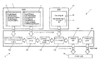
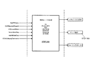
図1に評価システム1の概略図を示す。評価システム1は、インストルメントクラスタ5に設けられたプロセッサ3に実装されている。プロセッサ3は、車両運転データ9及び車両モードデータ11を提供するCANバス7に接続されている。プロセッサ3は、ルックアップマップ17のセットで構成されるカー・コンフィギュレーション・ファイル(CCF)15を格納するリードオンリーメモリ(ROM)等の記憶装置13にも接続されている。
FIG. 1 shows a schematic diagram of the
車両運転データ9は、エンジン回転数(EngineSpeed)、車両速度(VehicleSpeed)、加速及び減速率(車両速度差分/時間周期)、ブレーキスイッチステータス(BrakeSwitchStatus)、ブレーキ圧(BrakePressure)及び等価スロットルペダル位置(TM_PedalPos)を含むシステム変数を備える。システム変数は、車両センサによって取得される測定値から直接的に又は間接的に導出される。一例として、スロットルペダル位置がトルク要求マップから決定され、ブレーキペダル位置(BrakePressure)がマスターブレーキシリンダの圧力から導出される。
The
車両モードデータ11は、地形モード(ARCTerrainMode)、要求地形モード(TerrainModeReq)、追従モードでのアダプティブクルーズコントロールステータス(ACCStatus2)、クルーズコントロールステータス(CRUISEStatus2)、ヒルディセンデントモードステータス(HillDescentMode)及びローレンジステータス(CDiffMessageRequest)を備える。クルーズコントロールシステムは、「オフ」、「オーバーライド」又は「スタンバイ」モードにすることができ、ロードライブレンジは接続又は離脱が可能である。評価システム1は、例えば、クルーズコントロールが接続されるか又はロードライブレンジが選択されるか等のある特定のドライビングモードで無効化されるか抑制され得る。
The vehicle mode data 11 includes a terrain mode (ARC Terrain Mode), a requested terrain mode (Terrain Mode Req), an adaptive cruise control status (ACCS status 2) in a follow-up mode, a cruise control status (CRUIS Status 2), a hill descendant mode status (Hill Descend Mode), and a low range status ( CDiffMessageRequest). The cruise control system can be in “off”, “override” or “standby” mode, and the low drive range can be connected or disconnected. The
プロセッサ3は、現在の車両運転データ9を取得するために500ms毎にCANバス7に問い合わせを行う。ステップ100に示すように、プロセッサ3は、その500ms期間中に、測定されたシステム変数のそれぞれの平均値を算出する。なお、プロセッサ3は、過渡測定値を提供するために、その時間間隔の間に、各システム変数の変化率を算出する。変化率は、例えば、毎秒変化百分率(%/s)、車両速度の変化率(kph/s)及び毎秒圧力変化(bar/s)として決定されることができる。平均データ及び変化率データは、バッファに保持される。本実施形態では、エンジン回転数(EngineSpeed)、加速率(車両速度/時間)、車両速度(VehiceSpeed)、スロットルペダル位置(TMPedalPos)、ブレーキステータス(BrakeSwitchStatus)及びブレーキペダル位置(VirtualPedalPos)又は減速率(車両速度/時間)に関するシステム変数が分析される。
The
自動車の現在の運転モードは、CANバス7に提供された車両モードデータ11にアクセスすることによって、決定されることができる(ステップ110)。プロセッサ3は、どの走行モード(例えば、パーキング、ニュートラル、ドライブ、スポーツ)が現在選択されているか決定(判断)することができる。また、プロセッサ3は、地形モードが選択されているか、或いはクルーズコントロール/ヒルディセントが接続されているかをチェックすることもできる。
The current driving mode of the car can be determined by accessing the vehicle mode data 11 provided on the CAN bus 7 (step 110). The
次いで、プロセッサ3は、定常状態又は過渡事象にあるかをチェックする(ステップ120)。この試験は、後続の処理工程で、ルックアップマップ(ステップ100で算出された)の平均値の又は変化率のいずれかを使用すべきか否かを決定するものである。過渡マップは、問題になっているシステム変数に関する所定の固定値を超えている場合に基づいて選択されるであろう(例えば、加速率が特定の規定値よりも高い場合に過渡マップを選択することができる)。
The
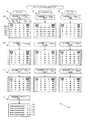
次いで、プロセッサ3は、分析する運転パラメータのそれぞれに関連するルックアップマップ17を選択するために、CFF(カー・コンフィギュレーション・ファイル)15にアクセスする(ステップ130)。図2に示すように、定常状態マップ(SS)、正の過渡マップ(PT)及び負の過渡マップ(NT)がCFF15内に3つの運転パラメータに対して格納されている。適切な定常状態又は過渡のルックアップマップ17が、定常状態/過渡試験の結果に応答して選択される(ステップ120)。なお、車両速度に関する閾値を定義する校正マップ(C)が、CFF15に格納されている。
The
ルックアップマップ17はそれぞれ一連の5つの経済性評価(E1,E2,E3,E4,E5)と関連する閾値を含んでいる。第1の経済性評価(E1)は、1(1)のスコアに対応し、効率の低いドライビングスタイルを表す(例えば、おそらく高い燃料消費量をもたらす)。第5の経済性評価(E5)は、5(5)のスコアに対応し、より効率的なドライビングスタイルを表す(例えば、おそらく低い燃料消費量をもたらす)。中間の経済性評価(E2,E3,E4)は、第1と第5の経済性評価(E1,E5)の中間においてより進展した尺度を提供するものである。表示される際、第1の経済性評価(E1)は赤色に着色され、第2、第3及び第4の経済性評価(E2,E3,E4)はオレンジ色に着色され、第5の経済性評価(E5)は緑色に着色される。
Look-up
各ルックアップマップ17内においては、5セットの閾値(図2の行R0,R1,R2,R3,R4で表される)があり、閾値の適切なセットの選択は、校正マップ(C)によって決定される。校正マップ(C)は、車両速度(Default_SpeedThreshold0からDefault_SpeedThreshold4)に対する閾値(V0,V1,V2,V3,V4)を含み、どのセットの閾値(R0,R1,R2,R3,R4)が分析に用いられるべきか決定するためのチェックが実行される。具体的には、ルックアップマップ17内の閾値(R0,R1,R2,R3,R4)のセットは、測定された車両速度に関して校正マップ(C)内で識別された閾値(V0,V1,V2,V3,V4)に対応するために選択される。例えば、車両速度が校正マップ(C)内の第2の閾値範囲(V1)内にある場合、ルックアップマップ(s)の第2のセットの閾値(R1)が分析に用いられる。車両速度の変化は、異なるセットの閾値(R0,R1,R2,R3,R4)の選択を生じ得る。
Within each
一度、閾値(R0,R1,R2,R3,R4)の適切なセットが校正マップ(C)を参照して決定されると、CANバス7から取得された各システム関数のアクセル(A)、スピード&エンジン(S)及びブレーキ(B)に関するルックアップマップへの比較が行われる。比較は、校正マップ(C)における比較に基づいて選択された閾値(R0,R1,R2,R3,R4)のセットに対して実行される。経済性評価(E1,E2,E3,E4,E5)は、この比較から決定される(ステップ140)。運転者フィードバックを提供するために、経済性評価(E1,E2,E3,E4,E5)に基づく経済性指標が表示モジュール19にリアルタイムで出力される。本実施形態では、経済性指標は、経済性評価(E1,E2,E3,E4,E5)に対応する。
Once the appropriate set of thresholds (R 0 , R 1 , R 2 , R 3 , R 4 ) has been determined with reference to the calibration map (C), the accelerator for each system function obtained from the CAN bus 7 A comparison is made to the lookup maps for (A), Speed & Engine (S) and Brake (B). The comparison is performed on a set of thresholds (R 0 , R 1 , R 2 , R 3 , R 4 ) selected based on the comparison in the calibration map (C). An economic evaluation (E 1 , E 2 , E 3 , E 4 , E 5 ) is determined from this comparison (step 140). In order to provide driver feedback, economic indicators based on economic evaluations (E 1 , E 2 , E 3 , E 4 , E 5 ) are output to the
経済性評価(E1,E2,E3,E4,E5)は、特定の旅程に対して算出される平均評価を可能にするためにバッファ内に格納される(ステップ150)。一度旅程が完了すると、平均評価は、表示モジュール19へ出力される。格付けは、将来の参照のため、例えば、昔の記録を提供するために保存することができる。
The economic evaluations (E 1 , E 2 , E 3 , E 4 , E 5 ) are stored in a buffer to allow an average evaluation calculated for a particular itinerary (step 150). Once the itinerary is complete, the average rating is output to the
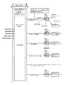
評価システムにおける処理ステップを表すフロー図を図3A〜3Eに示す。図3Aに示すように、エンジン回転数(EngineSpeed)、車両速度(VehicleSpeed)、スロットルペダル位置(TMPedalPos)、ブレーキステータス(BrakeSwitchStatus)及びブレーキペダル位置(VirtualPedalPos)に関するシステム変数が、500msの測定期間中に平均化される(ステップ200)。ブレーキステータス(BrakeSwitchStatus)は、パーキングブレーキが適用されたか否かを示す。 Flow diagrams representing processing steps in the evaluation system are shown in FIGS. As shown in FIG. 3A, system variables related to engine speed (EngineSpeed), vehicle speed (VehicleSpeed), throttle pedal position (TMPedalPos), brake status (BrakeSwitchStatus), and brake pedal position (VirtualPedalPos) are measured during a measurement period of 500 ms. Averaged (step 200). The brake status (BrakeSwitchStatus) indicates whether or not the parking brake is applied.
正規化データを生成するためにエンジン回転数、車両速度、スロットルペダル位置及びブレーキペダル位置に関する平均データが各補間ルックアップテーブルへ出力される(ステップ210)。その後の評価ステップは、車両/エンジンのタイプ又は構成に関係なく行うことができる。 Average data regarding engine speed, vehicle speed, throttle pedal position and brake pedal position is output to each interpolation look-up table to generate normalized data (step 210). Subsequent evaluation steps can be performed regardless of vehicle / engine type or configuration.
車両速度(VehicleSpeed)の変化率は、現在の車両速度データを前回の車両速度データと比較することによって算出される(ステップ220)。車両速度の変化率はまた、補間ルックアップテーブル及び相対的で絶対的な変化率値出力へ渡される(ステップ230)。変化率に対する相対値は「定常」、「正」又は「負」として分類され(ステップ240)、変化率に対する絶対値は更なる評価のために転送される(ステップ250)。 The change rate of the vehicle speed (VehicleSpeed) is calculated by comparing the current vehicle speed data with the previous vehicle speed data (step 220). The rate of change of vehicle speed is also passed to an interpolation look-up table and a relative absolute change rate value output (step 230). The relative value for the rate of change is classified as “steady”, “positive” or “negative” (step 240), and the absolute value for the rate of change is forwarded for further evaluation (step 250).
信号ノイズを除去するために、ヒステリシスが、エンジン回転数、車両速度、スロットル位置及びブレーキ圧のための正規化データに対して実行される(ステップ260)。図3Bに示すように、エアロ(空力)速度調整値を生成するために、正規化された車両速度データが速度ルックアップテーブルに適用される(ステップ270)。エアロ速度調整値は、車両速度に関連して増加する空力抵抗を反映させるために経済性評価に適用される修飾子である。 In order to remove signal noise, hysteresis is performed on the normalized data for engine speed, vehicle speed, throttle position and brake pressure (step 260). As shown in FIG. 3B, normalized vehicle speed data is applied to a speed look-up table to generate an aero speed adjustment value (step 270). The aero speed adjustment value is a qualifier that is applied to the economic evaluation to reflect the aerodynamic resistance that increases in relation to the vehicle speed.
エアロ速度調整とは独立して、正規化された車両速度データが分類され(ステップ280)車両速度分類データ出力が修飾子として他のデータチャネルに適用される。つまり、車両速度分類データが、車両速度の変化率、エンジン回転数、スロットル位置及びブレーキペダル位置の正規化データに適用される。 Independent of the aero speed adjustment, the normalized vehicle speed data is classified (step 280) and the vehicle speed classification data output is applied to other data channels as a qualifier. That is, the vehicle speed classification data is applied to the normalized data of the vehicle speed change rate, engine speed, throttle position, and brake pedal position.
図3Eに示すように、車両運転設定は、車両マップ選択を生成するために別個に分析される(ステップ290)。マップ選択は、「デフォルト」、「ダイナミック」、「ハイブリッド」又は「トランスファー」モードを備える(ステップ300)。得られたマップデータは、修飾子として、車両速度の変化率、エンジン回転数、スロットル位置及びブレーキペダル位置のための正規化データに適用される。 As shown in FIG. 3E, the vehicle driving settings are analyzed separately to generate a vehicle map selection (step 290). The map selection comprises a “default”, “dynamic”, “hybrid” or “transfer” mode (step 300). The obtained map data is applied as a modifier to normalized data for the rate of change in vehicle speed, engine speed, throttle position, and brake pedal position.
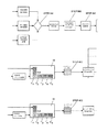
車両速度カテゴリ及び車両マップデータにより(ステップ310)、スロットルに対して(ステップ320)及びブレーキ圧に対して(ステップ330)修正された正規化データは、各経済性評価(E1,E2,E3,E4,E5)を生成するために各ルックアップテーブルに適用される。適切なルックアップテーブルが、測定されたパラメータに基づいて選択でき、例えば別々のルックアップテーブルが正の過渡(PT)、負の過渡(NT)又は定常状態(SS)条件のために参照することができる。図3C及び図3Dに示すように、運転者フィードバックを提供するために経済性評価(E1,E2,E3,E4,E5)が表示モジュール19へ出力される。
Normalized data modified for the throttle (step 320) and for the brake pressure (step 330) according to the vehicle speed category and vehicle map data (step 310) is obtained for each economic evaluation (E 1 , E 2 , E 3 , E 4 , E 5 ) are applied to each lookup table. Appropriate lookup tables can be selected based on measured parameters, eg, separate lookup tables referenced for positive transient (PT), negative transient (NT) or steady state (SS) conditions Can do. As shown in FIGS. 3C and 3D, economic evaluations (E 1 , E 2 , E 3 , E 4 , E 5 ) are output to the
車両速度データの場合、車両速度の変化率と定常状態の車両速度とを組み合わせることによって、組み合わされた車両速度データが決定される(ステップ340)。過大な加速度を反映させるようにするために、加速時においては、定常評価(即ち、定常状態ルックアップマップ−ステップ350)又は増加評価(即ち、正の過渡ルックアップマップ−ステップ360)のより低い方の評価に基づいて経済性評価(E1,E2,E3,E4,E5)が決定される。逆に、効率的な減速を反映させるために、減速時においては、経済性評価(E1,E2,E3,E4,E5)は、定常評価(即ち、定常状態ルックアップマップ−ステップ350)又は減少評価(即ち負の過渡ルックアップマップ−ステップ370)の高い方の評価に基づく。 In the case of vehicle speed data, the combined vehicle speed data is determined by combining the rate of change of the vehicle speed and the steady state vehicle speed (step 340). In order to reflect excessive acceleration, during acceleration, lower than steady state evaluation (ie steady state lookup map—step 350) or incremental evaluation (ie positive transient lookup map—step 360). The economic evaluation (E 1 , E 2 , E 3 , E 4 , E 5 ) is determined based on the evaluation of the other. On the contrary, in order to reflect efficient deceleration, the economic evaluation (E 1 , E 2 , E 3 , E 4 , E 5 ) is performed at the time of deceleration in the steady state evaluation (that is, steady state lookup map − Step 350) or based on the higher evaluation of the reduction evaluation (ie negative transient lookup map—step 370).
更には、空力抵抗を説明する経済性評価を修正するために、エアロ速度調整値が組み合わされた車両速度データに適用される(ステップ380)。車両速度の評価は、「クランプ(固定される)」か、又はそれが最小の経済性評価よりも落ちるのを抑制するように制限される(ステップ390)。 Further, an aero speed adjustment value is applied to the combined vehicle speed data to modify the economic evaluation describing aerodynamic drag (step 380). The vehicle speed rating is “clamped” or limited to prevent it from falling below a minimum economic rating (step 390).
評価システム1は、アクセル(A)、スピード&エンジン(S)及びブレーキ(B)のそれぞれに対する要約経済性評価も生成する。アクセル(A)、スピード&エンジン(S)及びブレーキ(B)のそれぞれに対して決定された経済性評価(E1,E2,E3,E4,E5)への重み付けを提供するために、重み付けルックアップマップが参照される(ステップ400)。アクセル(A)に対する平均経済性評価を決定するために、平均速度評価は、重み付けルックアップマップから決定された速度重み付けを乗算する(ステップ410)。スピード&エンジン(S)に対する平均経済性評価は、重み付けルックアップマップから決定されたスロットル重み付けと平均スロットルとを乗算することによって決定される(ステップ420)。ブレーキ(B)に対する平均経済性評価は、重み付けルックアップマップから決定されたブレーキ重み付けと平均ブレーキ評価を乗算することによって算出される(ステップ430)。アクセル(A)、スピード&エンジン(S)及びブレーキ(B)のそれぞれに対して決定された要約経済性評価を要約することによって、組み合わされた要約が生成される(ステップ440)。
The
組み合わされた要約は、効率スコアとして、例えば百分率で出力できる。 The combined summary can be output as an efficiency score, eg, as a percentage.
要約経済性評価及び/又は平均効率スコアは、特定の旅程又はユーザー定義の期間に対して生成できる。得られた旅行情報は、長期にわたる旅程(例えば、日、週、月)を網羅することができる。 A summary economic evaluation and / or average efficiency score can be generated for a particular itinerary or user-defined time period. The obtained travel information can cover a long-term itinerary (eg day, week, month).
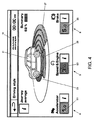
表示モジュール19への例示的なグラフィカルのリアルタイム表示を図4に示す。アクセル(A)、スピード&エンジン(S)及びブレーキ(B)等の運転パラメータに対する経済性評価(E1,E2,E3,E4,E5)が1から5の数値で表示されている。なお、経済性評価(E1,E2,E3,E4,E5)は、車両21のグラフィカル表現に関して同心円状のセグメントとして表示されている。アクセル(A)は、車両21の前方に突出する第1のセグメント23として表されており、スピード&エンジン(S)は、車両21の側に半径方向外向きに延びる第2のセグメント25として表されており、ブレーキ(B)は、車両21の後方に延びる第3のセグメント27として表されている。表示されるセグメントの数は、その運転パラメータに対して決定された経済性評価(E1,E2,E3,E4,E5)に対応して表示される。表示モジュール19は、運転者によって容易に解釈することが可能な運転パラメータの経済性評価の直感的な表示を提供する。
An exemplary graphical real-time display on the
車両の現在の旅程の詳細を提供するために、進化した旅行要約29を表示することもできる。図5Aに示すように、旅行要約29は、全体的経済性評価31を百分率で提供するとともに現在の旅程に対する平均燃料消費量(燃料1ガロン当たりの走行マイル−mpg)33を提供する。旅行要約29はまた、車両の過去3つの旅程に対する燃料1ガロン上がりの走行マイルと全体的評価の平均を提供する。車両によって完了した1ガロン当たりのマイル及び最も高い全体的経済性評価もまた比較のために提供される。
An evolved
図5Bに示すように、昔のデータ要約35も表示することができる。昔のデータ要約35は、旅程に関する1ガロン当たりのマイル(mpg)の平均とともに全体的経済性評価を備える。昔のデータは、現在の旅程及びその前の3つの工程について表示される。進行中の比較を可能にするために、例えば、特定の旅程に対し、例えば長期にわたる(例えば日、週、月)複数の旅程を網羅するために、運転者がユーザー定義の期間に対する要約データを保存することもできる。この要約データは別々の旅行(旅行A及び旅行B)として保存できる。最良の旅程性能(例えば最も高い経済評価及び燃料経済性)の要約もまた、将来の参照のために表示される。
An
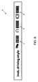
図6に占めるように、リアルタイムのドライビングスタイル要約37がアクセル(A)、スピード&エンジン(S)又はブレーキ(B)に関して表示できる。ドライビングスタイル要約37は、リアルタイム表示の簡易版であり、表示モジュール19上よりもむしろインストルメントクラスタに表示することができる。ドライビングスタイル要約37は、アクセル(A)、スピード&エンジン(S)又はブレーキ(B)に関する棒グラフを備える。棒グラフは、その運転パラメータに対して決定された経済性評価(E1,E2,E3,E4,E5)を表すために5本の棒をそれぞれ備える。
As shown in FIG. 6, a real-time
本発明に係る運転評価システム1は、様々な側面で変更することができる。
The driving
まず、スピード(S)の為の経済性評価は、エンジン回転数(RPM)及び/又は車両加速度(kph/s)に基づいて決定できる。第1の経済性評価(E1,E2,E3,E4,E5)を決定するために、定常状態ルックアップマップ(SSS)がエンジン回転数のためにアクセスされ、第2の経済性評価(E1,E2,E3,E4,E5)を決定するために、過渡ルックアップマップ(SPT;SNT)が車両加速度のためにアクセルされる。表示モジュール19に出力される経済性指標は、第1及び第2の評価(E1,E2,E3,E4,E5)の低い方に基づく。
First, the economic evaluation for speed (S) can be determined based on engine speed (RPM) and / or vehicle acceleration (kph / s). In order to determine the first economic evaluation (E 1 , E 2 , E 3 , E 4 , E 5 ), a steady state lookup map (S SS ) is accessed for the engine speed and the second In order to determine the economic evaluation (E 1 , E 2 , E 3 , E 4 , E 5 ), a transient lookup map (S PT ; S NT ) is accelerated for vehicle acceleration. The economic index output to the
更には、ルックアップマップから導出される経済性評価(E1,E2,E3,E4,E5)は、例えば車両速度に基づいて修正することができる。これは、速度が増加するにつれて増加する空力抵抗に起因する効率の低下を強調するために運転者にフィードバックを提供することができるものである。修飾子は、表示のために修正された評価出力及びスピード(S)のために決定された経済性評価(E1,E2,E3,E4,E5)に適用されることが想定される。修飾子は、関連する修飾子を持つ一連の範囲を含む修飾子ルックアップマップから決定することができる。 Furthermore, the economic evaluation (E 1 , E 2 , E 3 , E 4 , E 5 ) derived from the lookup map can be modified based on the vehicle speed, for example. This can provide feedback to the driver to highlight the loss in efficiency due to aerodynamic drag that increases as the speed increases. The modifier is assumed to be applied to the evaluation output (E 1 , E 2 , E 3 , E 4 , E 5 ) determined for the evaluation output and speed (S) modified for display. Is done. A qualifier can be determined from a qualifier lookup map that includes a series of ranges with associated qualifiers.
ブレーキ(B)の経済性評価(E1,E2,E3,E4,E5)は、マスターブレーキシリンダの圧力を参照して説明される。代替的に又は追加的には、経済性評価(E1,E2,E3,E4,E5)を決定するために車両の減速率を用いることができる。減速率の使用は、それが車両タイプに依存するものではなく、校正が潜在的により少なくてすむため、好ましい。 The economic evaluation (E 1 , E 2 , E 3 , E 4 , E 5 ) of the brake (B) will be explained with reference to the pressure of the master brake cylinder. Alternatively or additionally, the vehicle deceleration rate can be used to determine an economic evaluation (E 1 , E 2 , E 3 , E 4 , E 5 ). The use of a deceleration rate is preferred because it does not depend on the vehicle type and potentially requires less calibration.
運転評価システム1の運転は、特定の走行モードが接続された時に抑制され得る。例えば、運転評価システム1は、クルーズコントロールがスロットル/ブレーキ設定を積極的に調査する際に抑制され得る。しかしながら、運転評価システム1は、一度クルーズコントロールが、自動車が設定速度に到達すると車両−追従モードでは無いと決定するように運転し得る。グラフィック表示は、例えば、運転評価システム1が抑制される際に経済性評価がグレーアウトされることを示すように、部分的に又は完全に遮ることができる。
Driving of the driving
同様に、運転者が電話をかけるか逆転カメラが使用可能になったときに、グラフィック表示を部分的に又は完全に遮ることができる。 Similarly, the graphic display can be partially or completely blocked when the driver calls or the reversing camera becomes available.
運転評価システム1はまた、より効率的な運転を促進するためのヒントのライブラリを含むことができる。ヒントとしては、例えば、円滑な加速及び減速を促すこと、及び/又は車両修理をお勧めすること等であり得る。
The driving
本発明の範囲及び精神から逸脱することなく、種々の変更及び修正がここに記載されるシステムに対して行われることができる。本システムは、例えば、燃料消費量を改善するためにギアシフトの推薦を提供する等の運転者に追加的な情報を提供するために変形されることができる。 Various changes and modifications can be made to the system described herein without departing from the scope and spirit of the invention. The system can be modified to provide additional information to the driver, for example, providing gear shift recommendations to improve fuel consumption.
本発明は、内燃機関を有する自動車を参照して説明される。しかしながら、本発明は、ハイブリッド又は電気自動車に対して、例えば、電池の使用状況及び/又は範囲計算のフィードバックを提供するために実装され得ることが想定される。 The invention will be described with reference to a motor vehicle having an internal combustion engine. However, it is envisioned that the present invention may be implemented for hybrid or electric vehicles, for example, to provide battery usage and / or range calculation feedback.
1…(運転)評価システム
3…プロセッサ
7…CANバス
9…車両運転データ
11…車両モードデータ
13…記憶装置
15…カー・コンフィギュレーション・ファイル(CCF)
17…ルックアップマップ
19…表示モジュール
DESCRIPTION OF
17 ...
Claims (25)
前記自動車の第1の運転パラメータに関する第1のシステム変数を測定することと、
前記第1の運転パラメータと関連する第1のルックアップマップにアクセスすることであって、前記第1のルックアップマップが第1の閾値の1又は複数のセットを備えていることと、
前記第1のシステム変数を前記第1の閾値と比較して第1の経済性評価を決定することと、
前記第1の経済性評価に基づいて第1の経済性指標を出力すること
を含む方法。 A method for evaluating at least one driving parameter of a vehicle and providing driver feedback, comprising:
Measuring a first system variable relating to a first operating parameter of the vehicle;
Accessing a first lookup map associated with the first operating parameter, the first lookup map comprising one or more sets of first thresholds;
Comparing the first system variable with the first threshold to determine a first economic evaluation;
Outputting a first economic index based on the first economic evaluation.
前記自動車の第1の運転パラメータに関する第1のシステム変数に対応するセンサデータを受け付けるためのデータバスと、
前記第1の運転パラメータと関連する第1のルックアップマップを記憶するための記憶装置であって、
前記第1のルックアップマップが第1の閾値の少なくとも1のセットを備えており、
前記センサデータを前記第1の閾値のセットと比較し、第1の経済性評価を決定するように構成されたプロセッサと、
前記第1の経済性評価に基づいて第1の経済性指標を出力するための出力装置と
を備えるシステム。 A system for providing driver feedback in response to an evaluation of at least one driving parameter of a vehicle,
A data bus for receiving sensor data corresponding to a first system variable relating to the first operating parameter of the vehicle;
A storage device for storing a first lookup map associated with the first operating parameter;
The first lookup map comprises at least one set of first thresholds;
A processor configured to compare the sensor data with the first set of thresholds to determine a first economic evaluation;
And an output device for outputting a first economic index based on the first economic evaluation.
Applications Claiming Priority (3)
| Application Number | Priority Date | Filing Date | Title |
|---|---|---|---|
| GB1200283.8 | 2012-01-09 | ||
| GB1200283.8A GB2498224B (en) | 2012-01-09 | 2012-01-09 | Method and system for providing driver feedback |
| PCT/EP2013/050218 WO2013104621A2 (en) | 2012-01-09 | 2013-01-08 | Method and device for providing driver feedback |
Related Child Applications (1)
| Application Number | Title | Priority Date | Filing Date |
|---|---|---|---|
| JP2017173367A Division JP2018020776A (en) | 2012-01-09 | 2017-09-08 | Method and apparatus for providing feedback of driver |
Publications (2)
| Publication Number | Publication Date |
|---|---|
| JP2015507575A true JP2015507575A (en) | 2015-03-12 |
| JP2015507575A5 JP2015507575A5 (en) | 2015-11-12 |
Family
ID=45788654
Family Applications (2)
| Application Number | Title | Priority Date | Filing Date |
|---|---|---|---|
| JP2014550720A Pending JP2015507575A (en) | 2012-01-09 | 2013-01-08 | Method and apparatus for providing driver feedback |
| JP2017173367A Abandoned JP2018020776A (en) | 2012-01-09 | 2017-09-08 | Method and apparatus for providing feedback of driver |
Family Applications After (1)
| Application Number | Title | Priority Date | Filing Date |
|---|---|---|---|
| JP2017173367A Abandoned JP2018020776A (en) | 2012-01-09 | 2017-09-08 | Method and apparatus for providing feedback of driver |
Country Status (6)
| Country | Link |
|---|---|
| US (1) | US9619950B2 (en) |
| EP (1) | EP2802499B1 (en) |
| JP (2) | JP2015507575A (en) |
| CN (1) | CN104144836B (en) |
| GB (1) | GB2498224B (en) |
| WO (1) | WO2013104621A2 (en) |
Families Citing this family (14)
| Publication number | Priority date | Publication date | Assignee | Title |
|---|---|---|---|---|
| US20130173136A1 (en) * | 2012-01-04 | 2013-07-04 | Samsung Electronics Co., Ltd. | Apparatus and method for displaying vehicle-driving information in mobile terminal |
| GB2505667A (en) * | 2012-09-06 | 2014-03-12 | Jaguar Land Rover Ltd | Driver style feedback system to improve economy |
| US20150114087A1 (en) * | 2013-10-25 | 2015-04-30 | Ngk Spark Plug Co., Ltd. | Particulate measurement system |
| BR102013031053B1 (en) * | 2013-12-03 | 2020-12-15 | Continental Brasil Indústria Automotiva Ltda. | electronic system embedded in a land motor vehicle and data processing method for land motor vehicle |
| US9652900B2 (en) * | 2014-03-27 | 2017-05-16 | Jet Optoelectronics Co., Ltd. | Vehicle monitoring system |
| KR101558773B1 (en) * | 2014-05-22 | 2015-10-07 | 현대자동차주식회사 | Method for displaying dirver's propensity |
| US9657676B2 (en) * | 2015-02-04 | 2017-05-23 | Ford Global Technologies, Llc | Methods and systems for powertrain control |
| DE102015211985A1 (en) * | 2015-06-26 | 2016-12-29 | Init Innovative Informatikanwendungen In Transport-, Verkehrs- Und Leitsystemen Gmbh | Method and device for evaluating and / or influencing the driving behavior of a vehicle driver |
| US9630627B2 (en) * | 2015-09-10 | 2017-04-25 | Ford Global Technologies, Llc | Method and apparatus for adaptive drive control including fuel-economic mode engagement |
| CN106809142A (en) * | 2015-11-30 | 2017-06-09 | 大陆汽车投资(上海)有限公司 | Economic driving assistance method based on data analysis |
| US10825354B2 (en) | 2016-09-09 | 2020-11-03 | Apex Pro, LLC | Performance coaching method and apparatus |
| GB2559728B (en) * | 2017-01-25 | 2019-04-24 | Enigma Electronics Com Ltd | Fuel efficiency monitoring in a vehicle |
| FR3064236B1 (en) * | 2017-03-23 | 2021-09-24 | Drust | METHOD AND DEVICES FOR CALCULATING AN INSTANT DRIVING ENERGY EFFICIENCY INDEX OF A VEHICLE EQUIPPED WITH AN ENGINE |
| CN111845735B (en) * | 2020-08-07 | 2022-02-11 | 摩登汽车(盐城)有限公司 | Control method and system for electric vehicle test driving mode |
Citations (4)
| Publication number | Priority date | Publication date | Assignee | Title |
|---|---|---|---|---|
| JP2000247162A (en) * | 1999-02-26 | 2000-09-12 | Mitsubishi Motors Corp | Operating state evaluating device for vehicle |
| JP2008254529A (en) * | 2007-04-03 | 2008-10-23 | Toyota Motor Corp | Energy-saving drive promoting device |
| JP2010167836A (en) * | 2009-01-20 | 2010-08-05 | Fujitsu Ten Ltd | Economical-drive assist device |
| JP2011528430A (en) * | 2008-04-01 | 2011-11-17 | クランボ・ソシエダッド・アノニマ | Device for monitoring the process of driving a vehicle |
Family Cites Families (15)
| Publication number | Priority date | Publication date | Assignee | Title |
|---|---|---|---|---|
| US5123397A (en) * | 1988-07-29 | 1992-06-23 | North American Philips Corporation | Vehicle management computer |
| WO2008123808A1 (en) | 2007-04-10 | 2008-10-16 | Volvo Construction Equipment Ab | A method and a system for providing feedback to a vehicle operator |
| JP5111928B2 (en) * | 2007-04-20 | 2013-01-09 | ヤマハモーターエレクトロニクス株式会社 | Driving state display device and saddle riding type vehicle |
| FR2918325B1 (en) * | 2007-07-02 | 2009-09-18 | Peugeot Citroen Automobiles Sa | METHOD FOR AIDING THE DRIVING OF A MOTOR VEHICLE |
| EP2028058B1 (en) * | 2007-08-24 | 2010-12-01 | Audi AG | Motor vehicle with a display of information which describes the driving behaviour in respect of the fuel consumption |
| DE102008041618B4 (en) | 2008-08-27 | 2013-02-28 | Ford Global Technologies, Llc | Method and device for evaluating the driving style of a driver in a motor vehicle in relation to the fuel consumption |
| SE533135C2 (en) | 2008-11-21 | 2010-07-06 | Scania Cv Abp | Brake feedback system |
| DE102010018826A1 (en) | 2009-04-30 | 2010-11-18 | Daimler Ag | Method for response of driving conditions in reference to fuel consumption to driver of motor vehicle, involves determining multiple driving style parameters based on defined evaluation criteria |
| US8571731B2 (en) * | 2009-07-29 | 2013-10-29 | Searete Llc | Hybrid vehicle qualification for preferential result |
| DE102009049367A1 (en) | 2009-10-14 | 2011-04-21 | GM Global Technology Operations, Inc., Detroit | Method for graphical visualizing current driving conditions of motor vehicle, involves forming algorithm from sum of proportion that is proportional to accelerator pedal position and another proportion that depends on one of engine speed |
| IL201810A (en) * | 2009-10-29 | 2015-06-30 | Greenroad Driving Technologies Ltd | Method and device for evaluating a vehicle's fuel consumption efficiency |
| DE102009054235A1 (en) * | 2009-11-21 | 2011-05-26 | Bayerische Motoren Werke Aktiengesellschaft | Motor vehicle, has control device coupled to engine unit and display device such that current driving mode is determined, where information that is essential for reducing energy consumption is displayed depending on determined driving mode |
| MX357760B (en) * | 2011-02-25 | 2018-07-24 | Vnomics Corp | System and method for in-vehicle operator training. |
| US8924125B2 (en) * | 2011-03-31 | 2014-12-30 | Robert Bosch Gmbh | Perturbing engine performance measurements to determine optimal engine control settings |
| WO2013090543A1 (en) * | 2011-12-15 | 2013-06-20 | Ego-Gear, Llc | A device to increase fuel economy |
-
2012
- 2012-01-09 GB GB1200283.8A patent/GB2498224B/en active Active
-
2013
- 2013-01-08 WO PCT/EP2013/050218 patent/WO2013104621A2/en active Application Filing
- 2013-01-08 EP EP13702753.8A patent/EP2802499B1/en active Active
- 2013-01-08 CN CN201380012527.XA patent/CN104144836B/en active Active
- 2013-01-08 US US14/370,420 patent/US9619950B2/en active Active
- 2013-01-08 JP JP2014550720A patent/JP2015507575A/en active Pending
-
2017
- 2017-09-08 JP JP2017173367A patent/JP2018020776A/en not_active Abandoned
Patent Citations (4)
| Publication number | Priority date | Publication date | Assignee | Title |
|---|---|---|---|---|
| JP2000247162A (en) * | 1999-02-26 | 2000-09-12 | Mitsubishi Motors Corp | Operating state evaluating device for vehicle |
| JP2008254529A (en) * | 2007-04-03 | 2008-10-23 | Toyota Motor Corp | Energy-saving drive promoting device |
| JP2011528430A (en) * | 2008-04-01 | 2011-11-17 | クランボ・ソシエダッド・アノニマ | Device for monitoring the process of driving a vehicle |
| JP2010167836A (en) * | 2009-01-20 | 2010-08-05 | Fujitsu Ten Ltd | Economical-drive assist device |
Also Published As
| Publication number | Publication date |
|---|---|
| GB2498224B (en) | 2014-11-05 |
| EP2802499A2 (en) | 2014-11-19 |
| JP2018020776A (en) | 2018-02-08 |
| EP2802499B1 (en) | 2019-03-13 |
| CN104144836A (en) | 2014-11-12 |
| CN104144836B (en) | 2017-06-09 |
| US9619950B2 (en) | 2017-04-11 |
| WO2013104621A3 (en) | 2013-11-14 |
| GB201200283D0 (en) | 2012-02-22 |
| WO2013104621A2 (en) | 2013-07-18 |
| GB2498224A (en) | 2013-07-10 |
| US20140340211A1 (en) | 2014-11-20 |
Similar Documents
| Publication | Publication Date | Title |
|---|---|---|
| JP2018020776A (en) | Method and apparatus for providing feedback of driver | |
| US10055908B2 (en) | Real-time driver reward display system and method | |
| JP5596691B2 (en) | Operation method of driving evaluation system | |
| JP5410125B2 (en) | Method and apparatus for diagnosing driving maneuvers | |
| US9346466B2 (en) | Method for traffic-flow-conditioned adaptation of stopping processes to a synthetically modulated speed profile along a route travelled along by a vehicle and control device for carrying out the method | |
| JP2015507575A5 (en) | ||
| SE535868C2 (en) | Assessment method and systems for acceleration | |
| US20130046449A1 (en) | Fuel optimization display | |
| EP2036777B1 (en) | Method and system of providing driving data to a driver of a vehicle | |
| EP2359032B1 (en) | Gear feedback system | |
| CN110481558B (en) | Vehicle and analysis method of driving behavior thereof | |
| KR20110084447A (en) | Driving condition evaluation device and evaluation method | |
| CN101607553B (en) | Automotive slipstreaming support system | |
| JP5152865B2 (en) | Fuel efficient driving evaluation system | |
| US20150336586A1 (en) | Method, system, and computer rreadable medium for displaying driver's propensity | |
| US11499628B2 (en) | Apparatus for controlling shifting of a vehicle and a method therefor | |
| WO2014037427A1 (en) | System and method for providing driver feedback relating to a plurality of vehicle operating parameters, corresponding computer readable medium and vehicle with such a system | |
| JP4963095B2 (en) | Fuel efficient driving evaluation system | |
| CN112364082A (en) | Energy consumption analysis method and device for vehicle | |
| CN117382656B (en) | Fuel-saving driving guiding method, fuel-saving driving guiding device, fuel-saving driving guiding terminal and storage medium | |
| US11313302B1 (en) | Engine idle speed optimization | |
| CN116735226A (en) | Vehicle fuel consumption evaluation method and device, vehicle and storage medium | |
| US20230331245A1 (en) | Control method for boost mode of vehicle | |
| US20230331244A1 (en) | Control method for boost mode of vehicle | |
| KR20210146097A (en) | Vehicle driving guide device and method using the same |
Legal Events
| Date | Code | Title | Description |
|---|---|---|---|
| A521 | Request for written amendment filed |
Free format text: JAPANESE INTERMEDIATE CODE: A523 Effective date: 20150917 |
|
| A621 | Written request for application examination |
Free format text: JAPANESE INTERMEDIATE CODE: A621 Effective date: 20150917 |
|
| A977 | Report on retrieval |
Free format text: JAPANESE INTERMEDIATE CODE: A971007 Effective date: 20160530 |
|
| A131 | Notification of reasons for refusal |
Free format text: JAPANESE INTERMEDIATE CODE: A131 Effective date: 20160607 |
|
| A601 | Written request for extension of time |
Free format text: JAPANESE INTERMEDIATE CODE: A601 Effective date: 20160830 |
|
| A601 | Written request for extension of time |
Free format text: JAPANESE INTERMEDIATE CODE: A601 Effective date: 20161107 |
|
| A521 | Request for written amendment filed |
Free format text: JAPANESE INTERMEDIATE CODE: A523 Effective date: 20161118 |
|
| A02 | Decision of refusal |
Free format text: JAPANESE INTERMEDIATE CODE: A02 Effective date: 20170509 |