JP2015507178A - Positioning and repositioning device - Google Patents
Positioning and repositioning device Download PDFInfo
- Publication number
- JP2015507178A JP2015507178A JP2014546254A JP2014546254A JP2015507178A JP 2015507178 A JP2015507178 A JP 2015507178A JP 2014546254 A JP2014546254 A JP 2014546254A JP 2014546254 A JP2014546254 A JP 2014546254A JP 2015507178 A JP2015507178 A JP 2015507178A
- Authority
- JP
- Japan
- Prior art keywords
- repositioning device
- repositioning
- microphone
- light
- positioning point
- Prior art date
- Legal status (The legal status is an assumption and is not a legal conclusion. Google has not performed a legal analysis and makes no representation as to the accuracy of the status listed.)
- Granted
Links
- 238000000034 method Methods 0.000 claims abstract description 50
- 239000000853 adhesive Substances 0.000 claims description 18
- 230000001070 adhesive effect Effects 0.000 claims description 18
- 239000002390 adhesive tape Substances 0.000 claims description 8
- 238000005259 measurement Methods 0.000 claims description 8
- 239000003550 marker Substances 0.000 claims description 6
- 238000013500 data storage Methods 0.000 description 5
- 230000000007 visual effect Effects 0.000 description 3
- 241001310793 Podium Species 0.000 description 2
- 238000013459 approach Methods 0.000 description 2
- 238000004891 communication Methods 0.000 description 2
- 238000002372 labelling Methods 0.000 description 2
- 230000013011 mating Effects 0.000 description 2
- 230000021615 conjugation Effects 0.000 description 1
- 238000010586 diagram Methods 0.000 description 1
- 230000001747 exhibiting effect Effects 0.000 description 1
- 238000005286 illumination Methods 0.000 description 1
- 238000009434 installation Methods 0.000 description 1
- 230000007774 longterm Effects 0.000 description 1
- 238000012423 maintenance Methods 0.000 description 1
- 238000012986 modification Methods 0.000 description 1
- 230000004048 modification Effects 0.000 description 1
- 239000002985 plastic film Substances 0.000 description 1
- 229920006255 plastic film Polymers 0.000 description 1
- 230000001681 protective effect Effects 0.000 description 1
- 230000002787 reinforcement Effects 0.000 description 1
- 238000000926 separation method Methods 0.000 description 1
Images


Classifications
-
- G—PHYSICS
- G01—MEASURING; TESTING
- G01B—MEASURING LENGTH, THICKNESS OR SIMILAR LINEAR DIMENSIONS; MEASURING ANGLES; MEASURING AREAS; MEASURING IRREGULARITIES OF SURFACES OR CONTOURS
- G01B11/00—Measuring arrangements characterised by the use of optical techniques
- G01B11/14—Measuring arrangements characterised by the use of optical techniques for measuring distance or clearance between spaced objects or spaced apertures
-
- G—PHYSICS
- G01—MEASURING; TESTING
- G01B—MEASURING LENGTH, THICKNESS OR SIMILAR LINEAR DIMENSIONS; MEASURING ANGLES; MEASURING AREAS; MEASURING IRREGULARITIES OF SURFACES OR CONTOURS
- G01B11/00—Measuring arrangements characterised by the use of optical techniques
- G01B11/26—Measuring arrangements characterised by the use of optical techniques for measuring angles or tapers; for testing the alignment of axes
-
- G—PHYSICS
- G01—MEASURING; TESTING
- G01B—MEASURING LENGTH, THICKNESS OR SIMILAR LINEAR DIMENSIONS; MEASURING ANGLES; MEASURING AREAS; MEASURING IRREGULARITIES OF SURFACES OR CONTOURS
- G01B11/00—Measuring arrangements characterised by the use of optical techniques
- G01B11/002—Measuring arrangements characterised by the use of optical techniques for measuring two or more coordinates
-
- G—PHYSICS
- G01—MEASURING; TESTING
- G01C—MEASURING DISTANCES, LEVELS OR BEARINGS; SURVEYING; NAVIGATION; GYROSCOPIC INSTRUMENTS; PHOTOGRAMMETRY OR VIDEOGRAMMETRY
- G01C15/00—Surveying instruments or accessories not provided for in groups G01C1/00 - G01C13/00
- G01C15/02—Means for marking measuring points
-
- H—ELECTRICITY
- H04—ELECTRIC COMMUNICATION TECHNIQUE
- H04R—LOUDSPEAKERS, MICROPHONES, GRAMOPHONE PICK-UPS OR LIKE ACOUSTIC ELECTROMECHANICAL TRANSDUCERS; DEAF-AID SETS; PUBLIC ADDRESS SYSTEMS
- H04R1/00—Details of transducers, loudspeakers or microphones
- H04R1/08—Mouthpieces; Microphones; Attachments therefor
-
- Y—GENERAL TAGGING OF NEW TECHNOLOGICAL DEVELOPMENTS; GENERAL TAGGING OF CROSS-SECTIONAL TECHNOLOGIES SPANNING OVER SEVERAL SECTIONS OF THE IPC; TECHNICAL SUBJECTS COVERED BY FORMER USPC CROSS-REFERENCE ART COLLECTIONS [XRACs] AND DIGESTS
- Y10—TECHNICAL SUBJECTS COVERED BY FORMER USPC
- Y10S—TECHNICAL SUBJECTS COVERED BY FORMER USPC CROSS-REFERENCE ART COLLECTIONS [XRACs] AND DIGESTS
- Y10S33/00—Geometrical instruments
- Y10S33/21—Geometrical instruments with laser
Landscapes
- Physics & Mathematics (AREA)
- General Physics & Mathematics (AREA)
- Engineering & Computer Science (AREA)
- Radar, Positioning & Navigation (AREA)
- Remote Sensing (AREA)
- Acoustics & Sound (AREA)
- Signal Processing (AREA)
- Non-Portable Lighting Devices Or Systems Thereof (AREA)
- Mounting And Adjusting Of Optical Elements (AREA)
- Obtaining Desirable Characteristics In Audible-Bandwidth Transducers (AREA)
- Automatic Assembly (AREA)
- Studio Devices (AREA)
- Fastening Of Light Sources Or Lamp Holders (AREA)
- Details Of Audible-Bandwidth Transducers (AREA)
- Control And Safety Of Cranes (AREA)
- Vehicle Body Suspensions (AREA)
- Chain Conveyers (AREA)
- Accessories Of Cameras (AREA)
Abstract
第1の物体を第2の物体に対して位置決め及び再位置決めする再位置決めデバイスは、少なくとも1つの光源及び電源を含む。少なくとも1つの光源は、少なくとも2つの光線を生成し、各光線は、第2の物体上のビーム位置決め点を定めることができる。少なくとも1つの光源は、第1の物体に動作可能に接続される。電源は、少なくとも1つの光源に動作可能に接続される。再位置決めデバイスは、ビーム位置決め点を規定する手段を備える。第1の物体を第2の物体に対して位置決め及び再位置決めする方法も開示する。【選択図】 図7A repositioning device that positions and repositions a first object relative to a second object includes at least one light source and a power source. At least one light source generates at least two rays, each ray defining a beam positioning point on the second object. At least one light source is operably connected to the first object. The power source is operatively connected to at least one light source. The repositioning device comprises means for defining beam positioning points. A method for positioning and repositioning a first object relative to a second object is also disclosed. [Selection] Figure 7
Description
本発明は、第1の物体を第2の物体に対して位置決め及び再位置決めするデバイスに関する。 The present invention relates to a device for positioning and repositioning a first object relative to a second object.
物体を互いに位置決め及び再位置決めする作業は、煩雑で時間がかかる。特に、実質的に同じ場所で、一方の物体を他方の物体に対して位置決めすることは、煩雑で時間がかかる。例えば、ある写真に関して、撮影現場を再現するように、光、カメラ及び被写体を互いに再位置決めすることが煩雑で時間がかかるであろうことは、容易に想像できる。同様に、例えば、精密機械においては、1つの機械がメンテナンスのために移動される場合、後にこの機械を他の機械に対する同じ位置に再位置決めして、同様に他の機械と協働して動作できるようにすることが重要である。 The operation of positioning and repositioning objects relative to each other is cumbersome and time consuming. In particular, positioning one object relative to the other object at substantially the same location is cumbersome and time consuming. For example, it can be easily imagined that for a certain photo, it would be cumbersome and time consuming to reposition the light, the camera and the subject relative to each other to recreate the shooting site. Similarly, for example, in a precision machine, if one machine is moved for maintenance, it will later be repositioned to the same position relative to the other machine and will also work in conjunction with the other machine It is important to be able to do that.
一方の物体を他方の物体に対して再位置決めする課題は、音楽業界において、特に問題となる。楽器の相対的な位置及び楽器に対するマイクロホンの位置は、生成されるサウンドに影響することがある。また、室内の全ての物体の位置がサウンドに影響する可能性がある。したがって、所望のサウンドを実現する際に、全ての物体を相対的に再位置決めできるようにすることが重要である。なお、ある楽曲と他の楽曲とでは、最も望ましいサウンドが異なることがあり、このため、物体の位置を変更する必要があることがある。更に、レコーディングスタジオを借りるコストは高く、したがって、楽器及び設備を速やか且つ効率的に位置決めできれば、レコーディング時間をより生産的に利用することができる。現在、音楽業界では、バンドに金銭的な余裕があれば、アルバムが完成するまで、レコーディングスタジオが長期間に亘って借りられ、設備又は物体は動かされない。このような解決策は、非常に高価であることは明らかである。これに代えて、「目見当」で設備を同じ位置に配置し、これで間に合わせるか、或いは、サウンドが実質的に同じになるまで、相当な時間を費やして設備を調整することもある。 The problem of repositioning one object relative to the other is particularly problematic in the music industry. The relative position of the instrument and the position of the microphone relative to the instrument can affect the sound produced. Also, the location of all objects in the room can affect the sound. It is therefore important to be able to relatively reposition all objects when realizing the desired sound. Note that the most desirable sound may be different between a certain piece of music and another piece of music, and therefore the position of the object may need to be changed. Furthermore, the cost of renting a recording studio is high, so if the instruments and equipment can be quickly and efficiently positioned, the recording time can be used more productively. Currently, in the music industry, if the band has money, the recording studio is rented for a long period of time and equipment or objects are not moved until the album is completed. Obviously, such a solution is very expensive. Alternatively, the equipment may be placed in the same position with “look-ahead” to make it in time, or it may take a considerable amount of time to adjust the equipment until the sound is substantially the same.
そこで、第1の物体を第2の物体に対して位置決め及び再位置決めするデバイス及び方法が望まれている。 Thus, a device and method for positioning and repositioning a first object relative to a second object is desired.
第1の物体を第2の物体に対して位置決め及び再位置決めする再位置決めデバイスは、少なくとも1つの光源及び電源を含む。少なくとも1つの光源は、少なくとも2つの光線を生成し、各光線は、第2の物体上のビーム位置決め点を定めることができる。少なくとも1つの光源は、第1の物体に動作可能に接続される。電源は、少なくとも1つの光源に動作可能に接続される。再位置決めデバイスは、ビーム位置決め点を定める手段を備える。 A repositioning device that positions and repositions a first object relative to a second object includes at least one light source and a power source. At least one light source generates at least two rays, each ray defining a beam positioning point on the second object. At least one light source is operably connected to the first object. The power source is operatively connected to at least one light source. The repositioning device comprises means for defining a beam positioning point.
光源は、レーザビームであってもよい。 The light source may be a laser beam.
光源は、2つの光線を規定し、2つのビーム位置決め点を定めるための2つの光源であってもよい。 The light source may be two light sources for defining two rays and defining two beam positioning points.
光源は、3つの光線を規定し、3つのビーム位置決め点を定めるための3つの光源であってもよい。 The light source may be three light sources for defining three light beams and defining three beam positioning points.
ビーム位置決め点は、アドレスを規定してもよい。 The beam positioning point may define an address.
再位置決めデバイスは、第2の物体に関連するビーム位置決め点を定めるために用いられる、第2の物体上の位置決め点を規定する手段と共に用いてもよい。第2の物体上のビーム位置決め点を規定する手段は、マーカ、粘着性ロケータ、位置合わせシンボルを有する粘着性ロケータ、位置合わせシンボル、又はバーコードを有する粘着性ロケータのうちの1つであってもよい。 The repositioning device may be used with means for defining a positioning point on the second object that is used to define a beam positioning point associated with the second object. The means for defining a beam positioning point on the second object is one of a marker, an adhesive locator, an adhesive locator having an alignment symbol, an alignment symbol, or an adhesive locator having a barcode. Also good.
少なくとも1つの光源は、複数の光源であってもよく、各光源は、レーザビームであってもよく、各レーザビームは、ビーム位置決め点を定めるものであってよい。 The at least one light source may be a plurality of light sources, each light source may be a laser beam, and each laser beam may define a beam positioning point.
各レーザビームは、第1の物体から第2の物体までの距離を測定することによって第2の物体上のビーム位置決め点を定めるレーザ測定デバイスであってもよい。 Each laser beam may be a laser measurement device that determines a beam positioning point on the second object by measuring the distance from the first object to the second object.
距離測定は、アドレスを規定してもよく、アドレスは、第2の物体に関連する複数のビーム位置決め点を区別するために用いてもよい。 The distance measurement may define an address, which may be used to distinguish a plurality of beam positioning points associated with the second object.
再位置決めデバイスのヨーを測定する手段を更に備え、ヨーは、アドレスを規定するために用いてもよい。ヨーを測定する手段は、コンパスであってもよい。 Further comprising means for measuring the yaw of the repositioning device, the yaw may be used to define an address. The means for measuring yaw may be a compass.
再位置決めデバイスのピッチ及びロールを測定する手段を更に備え、ピッチ及びロールは、アドレスを規定するために用いてもよい。ピッチ及びロールを測定する手段は、ジャイロスコープであってもよい。 Further comprising means for measuring the pitch and roll of the repositioning device, the pitch and roll may be used to define an address. The means for measuring the pitch and roll may be a gyroscope.
再位置決めデバイスは、4つの面を有する四面体形状であってもよく、各光線は、異なる面から出射してもよい。四面体形状は、各面がふぞろいな四面体形状であってもよく、各ビームは、異なる面から垂直に出射してもよい。 The repositioning device may be a tetrahedron shape with four surfaces, and each ray may be emitted from a different surface. The tetrahedron shape may be a tetrahedron shape in which each surface is uniform, and each beam may be emitted vertically from different surfaces.
再位置決めデバイスは、複数の面を有していてもよく、各光線は、異なる面から出射してもよい。 The repositioning device may have a plurality of surfaces and each ray may exit from a different surface.
光源は、複数の光源であってもよく、各光源は、光ビームを規定し、各光ビームは、ビーム位置決め点を定めるものであってよい。 The light source may be a plurality of light sources, each light source defining a light beam, and each light beam defining a beam positioning point.
再位置決めデバイスは、第1の物体に取り外し可能に取り付けてもよい。これに代えて、再位置決めデバイスは、第1の物体に一体に取り付けてもよい。 The repositioning device may be removably attached to the first object. Alternatively, the repositioning device may be integrally attached to the first object.
再位置決めデバイスは、マウントを更に備えていてもよく、マウントは、第1の物体に取り付けられ、再位置決めデバイスは、マウントに取り外し可能に取り付けてもよい。マウントは、複数のマウント位置を有していてもよい。マウントは、マウントを第1の物体に取り付けるための粘着テープを含んでいてもよい。粘着テープは、両面テープであってもよい。 The repositioning device may further comprise a mount, the mount may be attached to the first object, and the repositioning device may be removably attached to the mount. The mount may have a plurality of mounting positions. The mount may include an adhesive tape for attaching the mount to the first object. The adhesive tape may be a double-sided tape.
各ビームは、方向を有し、各ビームの方向は、調整可能であってもよく、ビームの方向は、第1の物体に対して再位置決め可能であってもよい。各ビームは、ビーム位置決め点が第2の物体上の所定の点になるように調整してもよい。各ビームの方向は、ロック可能であってもよい。 Each beam has a direction, the direction of each beam may be adjustable, and the direction of the beam may be repositionable with respect to the first object. Each beam may be adjusted so that the beam positioning point is a predetermined point on the second object. The direction of each beam may be lockable.
各ビームは、方向を有していていもよく、各ビームの方向は、再位置決めデバイスに対して固定される。 Each beam may have a direction, and the direction of each beam is fixed relative to the repositioning device.
第1の物体は、マイクロホンであってもよく、再位置決めデバイスは、マイクロホンに一体に取り付けられる。 The first object may be a microphone and the repositioning device is integrally attached to the microphone.
第1の物体は、マイクロホンであってもよく、マイクロホンは、クリップに取り外し可能に取り付けられ、再位置決めデバイスは、クリップに一体に取り付けられる。クリップは、マイクスタンドに取り付けてもよい。 The first object may be a microphone, the microphone is removably attached to the clip, and the repositioning device is integrally attached to the clip. The clip may be attached to a microphone stand.
第1の物体は、マイクロホンであってもよく、マウントを更に備え、マウントは、マイクロホンに取り付けてもよく、再位置決めデバイスは、マウントに取り外し可能に取り付けられる。マウントは、マウントをマイクロホンに取り付ける粘着テープを含んでいてもよい。 The first object may be a microphone, further comprising a mount, the mount may be attached to the microphone, and the repositioning device is removably attached to the mount. The mount may include an adhesive tape that attaches the mount to the microphone.
第1の物体は、カメラ、1台の機械、照明、楽器、アンプリファイヤ、マイクロホン、又はスタンドのうちの1つであってもよい。第2の物体は、部屋、壁、天井、1台の機械、楽器、アンプリファイヤ、又は芸術作品のうちの1つであってもよい。第1の物体は、マイクロホンであってもよく、第2の物体は、ドラムであってもよい。第1の物体は、マイクロホンであってもよく、第2の物体は、アンプリファイヤ内蔵スピーカユニットであってもよい。 The first object may be one of a camera, a machine, a light, a musical instrument, an amplifier, a microphone, or a stand. The second object may be one of a room, a wall, a ceiling, a machine, a musical instrument, an amplifier, or a work of art. The first object may be a microphone and the second object may be a drum. The first object may be a microphone, and the second object may be an amplifier built-in speaker unit.
定められた再位置決め点のそれぞれは、紫外線光下でのみ可視になってもよい。位置決め点を定める手段は、各位置決め点に対応する第2の物体に固有の情報を登録するものであってもよい。 Each of the defined repositioning points may only be visible under ultraviolet light. The means for determining the positioning points may register information unique to the second object corresponding to each positioning point.
電源は、バッテリであってもよい。 The power source may be a battery.
各ビームは、画像を定めるようにしてもよい。画像は、ドット又はグリッドパターンであってもよい。画像は、ロゴであってもよい。 Each beam may define an image. The image may be a dot or grid pattern. The image may be a logo.
光源は、複数の光線を規定する複数の光源であってもよく、各光線は、異なる色を有していてもよい。 The light source may be a plurality of light sources that define a plurality of light beams, and each light beam may have a different color.
再位置決めデバイスは、少なくとも2つの光線が再位置決めデバイスの一端から出射され、再位置決めデバイスの他端から出射される2つの光線を更に含むように構成してもよく、再位置決めデバイスの一端から出射される光線は、第1の物体を位置決めするために使用され、他端から出射される光線は、第2の物体を位置決めするために使用される。 The repositioning device may be configured such that at least two rays are emitted from one end of the repositioning device and further include two rays emitted from the other end of the repositioning device, emanating from one end of the repositioning device. The emitted light is used to position the first object, and the light emitted from the other end is used to position the second object.
再位置決めデバイスは、再位置決めデバイスの一端から出射される少なくとも2つの光線が複数の光線であり、再位置決めデバイスの他端から出射される少なくとも2つの光線が複数の光線であるように構成してもよい。 The repositioning device is configured such that at least two rays emitted from one end of the repositioning device are a plurality of rays and at least two rays emitted from the other end of the repositioning device are a plurality of rays. Also good.
各ビーム位置決め点に関連するデータは、再位置決めデバイス内のストレージデバイス、外部ストレージデバイス、又はこれらの両方に保存してもよい。更なるデータ、例えば、日付、楽曲、グループ、レコーディングセッション、楽器、アンプリファイヤ、マイクロホン、又はこれらの組合せの1つを保存してもよい。 Data associated with each beam positioning point may be stored on a storage device within the repositioning device, an external storage device, or both. Further data may be stored, for example one of date, song, group, recording session, instrument, amplifier, microphone, or a combination thereof.
第1の物体を第2の物体に対して位置決め及び再位置決めする方法は、第1の物体を第2の物体に対して位置決めし、設定位置を定めるステップであって、第1の物体が、それぞれが第2の物体に関連するビーム位置決め点を定める少なくとも2つの光線を生成する少なくとも1つの光源と、少なくとも1つの光源に動作可能に接続された電源と、ビーム位置決め点を定める手段とを備える再位置決めデバイスに対して位置決めされるステップと、各ビーム位置決め点に関して第2の物体に対する位置決め点を定めるステップと、第1の物体及び第2の物体の少なくとも1つを移動させるステップと、各ビーム位置決め点がビーム位置決め点に一致するように第1の物体を第2の物体に対して移動させるステップとを有する。 A method of positioning and repositioning a first object with respect to a second object is a step of positioning the first object with respect to the second object and determining a set position, wherein the first object is At least one light source for generating at least two rays each defining a beam positioning point associated with the second object, a power source operably connected to the at least one light source, and means for determining the beam positioning point Positioning with respect to the repositioning device; defining a positioning point for the second object with respect to each beam positioning point; moving at least one of the first object and the second object; Moving the first object relative to the second object such that the positioning point coincides with the beam positioning point.
再位置決めデバイスは、第1の物体に動作可能に取り付けてもよい。 The repositioning device may be operably attached to the first object.
再位置決めデバイスは、少なくとも2つの光線が再位置決めデバイスの一端から出射され、再位置決めデバイスの他端から出射される2つの光線を更に含むように構成してもよく、再位置決めデバイスの一端から出射される光線は、第1の物体を位置決めするために使用され、他端から出射される光線は、第2の物体を位置決めするために使用される。 The repositioning device may be configured such that at least two rays are emitted from one end of the repositioning device and further include two rays emitted from the other end of the repositioning device, emanating from one end of the repositioning device. The emitted light is used to position the first object, and the light emitted from the other end is used to position the second object.
方法は、再位置決めデバイスを第1の物体に動作可能に取り付けるステップを更に有していてもよい。 The method may further comprise operably attaching a repositioning device to the first object.
方法は、第1の物体をマウントに取り付け、再位置決めデバイスをマウントに取り外し可能に取り付けるステップを更に有していてもよい。 The method may further comprise attaching the first object to the mount and removably attaching the repositioning device to the mount.
方法は、所定の配置において、各ビーム位置決め点に関して、第2の物体上の位置決め点を特定するステップを更に有していてもよい。 The method may further comprise identifying a positioning point on the second object for each beam positioning point in a predetermined arrangement.
方法は、各ビームの方向をロックするステップを更に有していてもよい。 The method may further comprise locking the direction of each beam.
位置決め点を定める手段は、各位置決め点に対応する第2の物体に固有の情報登録するものであってもよく、方法は、各位置決め点に対応する第2の物体に固有の情報を登録するステップを更に有していてもよい。 The means for determining the positioning points may register information specific to the second object corresponding to each positioning point, and the method registers information specific to the second object corresponding to each positioning point. A step may be further included.
各ビーム位置決め点に関連するデータは、再位置決めデバイス内のストレージデバイス、外部ストレージデバイス、又はこれらの両方に保存してもよく、方法は、データを登録するステップを更に有していてもよい。更なるデータは、日付、楽曲、グループ、レコーディングセッション、楽器、アンプリファイヤ、マイクロホン、又はこれらの組合せのようなものを保存してもよい。 Data associated with each beam positioning point may be stored on a storage device in the repositioning device, an external storage device, or both, and the method may further comprise registering the data. Further data may store such things as dates, songs, groups, recording sessions, instruments, amplifiers, microphones, or combinations thereof.
再位置決めデバイスの更なる特徴は、以下の詳細な説明によって開示され又は明らかとなる。添付の図面を参照し、例示のみを目的として再位置決めデバイスについて説明する。 Additional features of the repositioning device will be disclosed or apparent from the following detailed description. The repositioning device will be described by way of example only with reference to the accompanying drawings.
ここに開示する再位置決めデバイスは、マイクロホン、カメラ、照明設備、スピーカ、楽器、又は設備の配置を補助することによって、産業、商業、又は家庭における多くのセッティング、並びに、写真及び音楽産業におけるアーチスト、技術者、グラフィックデザイナ、又は写真家の個々の要求を効果的且つ効率的に満たす手段を提供する。再位置決めデバイスは、まず、物体及び設備の位置にアドレスを割り当て、それらの物体及び設備を動かした後に、物体及び設備を以前と同じ好ましい配置に再構成又は再位置決めできることを約束することによって個々を補助する。再位置決めデバイスは、位置決め点を規定する手段と連携して使用される。 The repositioning device disclosed herein assists in the placement of microphones, cameras, lighting equipment, speakers, musical instruments, or equipment, thereby enabling many settings in the industry, commerce, or home, as well as artists in the photography and music industries, It provides a means to effectively and efficiently meet the individual needs of engineers, graphic designers or photographers. The repositioning device first assigns addresses to the locations of the objects and equipment, and after moving those objects and equipment, the individual and the equipment by promising that they can be reconfigured or repositioned in the same preferred arrangement as before. Assist. The repositioning device is used in conjunction with a means for defining positioning points.
物体を位置決めする方法の第1のフェーズでは、物体及び設備が正しい配置にあるとみなされると、設備の他のピースに対して、及びその設備が設置されている3次元環境に対して、設備の各ピースの相対的配置が確定される。これは、位置決めされた第1の物体に、例えば、レーザモジュールからなる再位置決めデバイスを貼り付け、光線を出射し、位置決め点を定め、投射光線が当たった第2の物体上における位置にロケータを貼り付け、それらの役割に応じてロケータをラベリングすることによって達成される。これに代えて、両端から光線を出射する再位置決めデバイスを用いて、第1の物体に対して再位置決めデバイスを同様に配置し、両端から光線を出射し、投射光線が両方の物体に当たった位置にロケータを貼り付け、それらの役割に応じてロケータをラベリングすることによって、両方の物体上で位置決め点を定めることにしてもよい。第1の物体に動作可能に接続される再位置決めデバイスに関連する第2の物体上の複数の位置決め点は、第2の物体に対する第1の物体のアドレスである。この手順は、個々が求めるセットアップの生成に寄与する各物体及び設備のピースについて繰り返される。このようにして、位置決めされた全ての必要な物体及び設備のピースにアドレスが割り当てられると、この配置は、状況に応じて、新しい又は異なる配置に変更され、又は分離されても、元の状態に戻すことができる。物体の周囲の3次元環境に対して物体のアドレスを規定するこの第1のフェーズは、将来において、いつでも同じ空間的セットアップを再構築するために使用できる固定具又はジグの構造に類似している。このジグは、実際の部品を有していないので、仮想ジグとみなすことができる。 In the first phase of the method of positioning an object, once the object and equipment are considered in the correct arrangement, the equipment is relative to the other pieces of equipment and to the three-dimensional environment in which the equipment is installed. The relative arrangement of each piece is determined. For example, a repositioning device composed of, for example, a laser module is attached to a first object that has been positioned, a light beam is emitted, a positioning point is determined, and a locator is positioned at a position on the second object that has been projected. This is accomplished by pasting and labeling locators according to their role. Instead, using a repositioning device that emits light rays from both ends, the repositioning device is similarly arranged with respect to the first object, the light rays are emitted from both ends, and the projected light rays hit both objects. A positioning point may be determined on both objects by attaching a locator at a position and labeling the locator according to their roles. The plurality of positioning points on the second object associated with the repositioning device operably connected to the first object is the address of the first object relative to the second object. This procedure is repeated for each object and piece of equipment that contributes to the creation of the setup that the individual seeks. In this way, once all the necessary objects and pieces of equipment that have been positioned have been assigned addresses, this arrangement can be changed to a new or different arrangement or separated, depending on the situation. Can be returned to. This first phase of defining the address of the object relative to the 3D environment surrounding the object is similar to a fixture or jig structure that can be used at any time in the future to reconstruct the same spatial setup. . Since this jig has no actual parts, it can be regarded as a virtual jig.
上述した第1のフェーズの説明は、再位置決めデバイス自体に関して各光線の投射方向が固定されており、これらに応じて周囲の環境内にロケータが貼り付けられる再位置決めデバイスの使用について特に適合する。再位置決めデバイス自体に関して各光線の投射方向が調整可能である場合、物体を位置決めする方法の第1のフェーズは、これに代えて、次のようなものとすることができる。まず、上述と同様に、物体及び設備が正しい配置であることを確認するが、この場合、再位置決めデバイスは、周囲の環境内の表面に貼り付けられ、光線が調整可能であるため、光線を物体自体に向け、光線が当たっている物体の表面上の点をロケータによってマーキングする。この場合、ロケータの役割及び位置、再位置決めデバイス及びセッティングの配置、再位置決めデバイス又はモジュールに関して各光線が出射された方向の全てを登録して、セットアップを再構築する際に、これらの特定の詳細を参照することができるようにする。この物体の位置決め方法は、位置決めされる物体が比較的大きく、物体の表面上にロケータを大きく離して貼り付けることができる場合に、良好に機能する。位置決めされる物体が小さすぎると、物体の表面に投射される全ての光線が1つの位置に集束する傾向があり、配置された物体のピッチ、ロール及びヨーの信頼度が低下しやすい。 The description of the first phase described above is particularly suitable for the use of a repositioning device in which the projection direction of each ray is fixed with respect to the repositioning device itself, and accordingly a locator is applied in the surrounding environment. If the projection direction of each ray is adjustable with respect to the repositioning device itself, the first phase of the method of positioning the object can instead be as follows. First, as before, make sure that the objects and equipment are in the correct position, but in this case the repositioning device is affixed to the surface in the surrounding environment and the light can be adjusted, A point on the surface of the object that is hit by the light beam is marked by the locator toward the object itself. In this case, these specific details will be used when restructuring the setup by registering all of the directions in which each ray is emitted with respect to the role and position of the locator, the positioning of the repositioning device and settings, the repositioning device or module To be able to refer to. This object positioning method works well when the object to be positioned is relatively large and the locator can be attached to the surface of the object with a large separation. If the object to be positioned is too small, all the rays projected on the surface of the object tend to converge at one position, and the pitch, roll and yaw reliability of the arranged object tends to decrease.
物体を位置決めする方法の第2のフェーズでは、位置決めするべき物体に再位置決めデバイスを貼り付け、光線を出射し、モジュールからの各投射光線が正しいロケータに当たるまで、又はロケータラベル若しくは登録された情報によって指示される位置決め点に一致するまで、物体の配置を調整することによって、設備の他のピースや周囲の環境に対して、物体及び設備を以前の配置に位置決めすることができる。登録された情報は、各位置決め点に対応する第2の物体に固有の情報であってもよい。例えば、登録された情報は、第2の物体の3つの特定の角であってもよい。この手順は、先のセットアップと同様に物体の全体の配置が再構築されるまで、配置構成内の各物体及び設備のピースについて繰り返される。物体の空間的配置を初期のセットアップと同様に再構築するこの第2のフェーズは、仮想ジグの使用に類似している。 In the second phase of the method of positioning the object, a repositioning device is applied to the object to be positioned, a light beam is emitted and each projected beam from the module hits the correct locator or by a locator label or registered information By adjusting the placement of the object until it matches the indicated positioning point, the object and equipment can be positioned in the previous placement relative to other pieces of equipment and the surrounding environment. The registered information may be information unique to the second object corresponding to each positioning point. For example, the registered information may be three specific corners of the second object. This procedure is repeated for each object and piece of equipment in the arrangement until the entire arrangement of objects is reconstructed as in the previous setup. This second phase of reconstructing the spatial arrangement of objects as well as the initial setup is similar to the use of virtual jigs.
また、光線を調整可能な再位置決めデバイスを使用する場合、物体を位置決めする方法の代替となる第2のフェーズは、次の通りである。この場合、周囲の環境内の同じ位置に再位置決めデバイスを貼り付け、第1の物体に対して第1のフェーズと同じになるように各投射光線の方向を調整し、光線を出射し、モジュールからの各投射光線が正しいロケータに当たるまで、又は各投射光線がセットアップに関連して登録された情報によって指示される位置決め点に位置合わせされるまで、物体の配置を調整することによって、設備の他のピースや周囲の環境に対して、物体及び設備を以前の配置に位置決めすることができる。 Also, when using a repositioning device that can adjust the beam, a second phase that is an alternative to the method of positioning the object is as follows. In this case, the repositioning device is affixed at the same position in the surrounding environment, the direction of each projection light beam is adjusted to be the same as the first phase with respect to the first object, the light beam is emitted, and the module By adjusting the placement of the object until each projected ray from hits the correct locator or until each projected ray is aligned with the registration point indicated by the information registered in connection with the setup, The objects and equipment can be positioned in the previous arrangement relative to the piece and the surrounding environment.
物体を位置決めする方法の第1及び第2のフェーズの両方において使用されるデバイスは、光線、再位置決めデバイス、マウント及びロケータから構成される。例えば、使用される光線は、数100メートル以下の有効範囲を有する低ワットタイプのものであってもよく、光自体は、物理的に小さく、通常、長さ数センチメートル、直径数ミリメートル程度のものであってもよい。包括的に言えば、再位置決めデバイスは、1つ以上の光線、スイッチ及びバッテリを備え、これらは全てハウジング内に組み込まれている。再位置決めデバイスが物体に一体化される場合、再位置決めデバイスのハウジングは、物体自体の一部であってもよく、バッテリ以外の電源を使用してもよい。物体に取り外し可能に取り付けできる再位置決めデバイスでは、取り外し可能な取付手段は、機械的手段、磁気的手段、接着手段であってもよく、他の適切な幾つの手法を用いてもよい。マウントと共に使用されることが意図された再位置決めデバイスの場合、モジュールをマウントに取り外し可能に取り付ける手段は、モジュールを確実に安定して取り付けることができると共に、必要に応じてマウントから容易に取り外すことができるように構成される。 The devices used in both the first and second phases of the method for positioning an object consist of a beam, a repositioning device, a mount and a locator. For example, the light rays used may be of the low watt type with an effective range of several hundred meters or less, and the light itself is physically small, usually on the order of a few centimeters in length and a few millimeters in diameter. It may be a thing. In general terms, the repositioning device comprises one or more light beams, a switch and a battery, all of which are integrated within the housing. If the repositioning device is integrated into the object, the housing of the repositioning device may be part of the object itself and may use a power source other than the battery. In a repositioning device that can be removably attached to an object, the removable attachment means may be mechanical means, magnetic means, adhesive means, and any other suitable technique may be used. For repositioning devices intended to be used with a mount, the means for removably attaching the module to the mount ensures that the module can be securely and stably attached and can be easily removed from the mount as needed. It is configured to be able to.
最初の状態と同様に再位置決めデバイスが物体に再び取り付けられることを保証するために、物体に取り外し可能に取り付けられる再位置決めデバイスの配置及び向きは、幾つかの位置のみに制限することが好ましい。再位置決めデバイスをマウントに取り外し可能に取り付けできる実施形態では、マウント自体は、物体に取り外し可能に取り付けられるものであってもよく、物体に一度だけ固定されるものであってもよく、物体と一体にされたものであってもよい。マウントは、物体に取り付けることができる側面と、再位置決めデバイスをマウントに取り外し可能に取り付けることができる第2の側面とを有する。マウントの主な役割は、幾つかの個々のマウントを用いて、全ての物体に亘って再位置決めデバイスの取り外し可能な取り付け手段を規格化することによって、単一の再位置決めデバイスが様々な物体と共に使用できるようにすることである。マウントは、単純で安価なユニットである。更に、再位置決めデバイスの取り外し可能な取付手段は、全てのマウントタイプに共通であるが、様々な物体への異なるマウントの取付手段が複数ある複数のマウントタイプを準備してもよい。 In order to ensure that the repositioning device is reattached to the object as in the initial state, the placement and orientation of the repositioning device removably attached to the object is preferably limited to only a few positions. In embodiments where the repositioning device can be removably attached to the mount, the mount itself can be removably attached to the object, can be secured to the object only once, and can be integral with the object. It may be made. The mount has a side that can be attached to the object and a second side that can removably attach the repositioning device to the mount. The main role of the mount is to use several individual mounts to standardize the removable mounting means of the repositioning device across all objects so that a single repositioning device can be used with various objects. Is to be able to use it. The mount is a simple and inexpensive unit. Furthermore, the removable attachment means of the repositioning device is common to all mount types, but multiple mount types with multiple attachment means for different mounts on various objects may be provided.
図1は、ここに開示するデバイス及び方法によって位置決めされているカメラ1及び三脚5を示している。再位置決めデバイス8は、カメラ1の規格化されたアクセサリマウント(accessory mount)においてカメラ1に取り付けられるように適応化されており、スタジオの床にドットを投写する3個の投射光線6を有する。この投射光線6が投射された床の点にロケータ4を貼り付けることによって、カメラ1を同じ場所に位置決めすることができる。これに代えて、再位置決めデバイス8は、三脚5の規格化されたカメラマウント7に取り付けるように適応化してもよい。この場合、再位置決めデバイス8は、三脚5に取り付けることができ、したがって、三脚5を位置決めして、再位置決めデバイス8を取り外した後に、カメラ1を取り付けてもよい。
FIG. 1 shows a
図1では、ここに開示する方法を用いて、三脚に取り付けられるカメラを位置決めしているが、位置決めされる物体が人である場合、再位置決めデバイス及びロケータを用いて、その人の椅子、マイクスタンド、譜面台、マット、又は他の家具等を位置決めし、その人が椅子に座り、又はマイクスタンド若しくは譜面台の前に立つと、その人が効果的に位置決めされるようにしてもよい。 In FIG. 1, the method disclosed herein is used to position a camera attached to a tripod, but if the object to be positioned is a person, the repositioning device and locator are used to position the person's chair, microphone A stand, music stand, mat, or other furniture may be positioned so that the person is effectively positioned when sitting on a chair or standing in front of a microphone stand or music stand.
図2は、四面体形状の再位置決めデバイス9を示している。この実施形態の再位置決めデバイスは、4個の面11及び6個の辺13を有する。再位置決めデバイス又はモジュール9の4つの面11のそれぞれには、光源3が組み込まれている。したがって、各面11から光線を出射することができ、この光線は、好ましくは、面11に対して垂直である。各面11は、光源3を駆動するスイッチ15を有する。これに代えて、1つのスイッチによって全ての光源を駆動してもよい。光源は、複数の光線に分割される単一の光源であってもよく、独立した複数の光源を組み込んでもよい。光源は、光線の光源であってもよい。光は、レーザビームであってもよく、ビームが壁、床、天井又は他の物体に当たると、物体に赤いドットが映し出される。これに代えてビームは、異なる色であってもよい。図に示すように、デバイス9は、各面がふぞろいな四面体であり、各面11は、それぞれふぞろいな三角形の形状を有し、したがって、モジュール9の各面11及び各辺13は、他とは異なる固有の(unique)ものである。モジュール9の各面11には、接着剤が塗布されており、モジュール9は、平坦な如何なる面にも取り外し可能に取り付けることができる。接着剤は、接着剤が両面に塗布された両面テープによって提供してもよく、両面テープの一方の面は、モジュール9に取り付けられ、他方の面によって、モジュール9を、物体の表面に取り外し可能に取り付けることができる。テープは、長期間の使用によって粘着性を失う傾向があるので、必要に応じて、テープを新しいテープに交換してもよい。更に、物体を実質的に動かすことなく、物体からモジュール9を取り外すことができるテープを実現するために、テープの面の粘着性を慎重に制御し、テープのサイズ及び形状を、テープが取り付けられるモジュール9の面11のサイズ及び形状に慎重に適合化する必要がある場合がある。これに代えて、磁石又は他の手段によって、モジュール9が取り外し可能に取り付けられるようにしてもよい。実際の現場では、まず、物体を位置決めし、第1の物体の表面にモジュール9を貼り付け、光源3をオンにして光線を出射させ、第2の物体上でビーム位置決め点を定める。そして、ビーム位置決め点において、この表面に、位置決め点を規定するロケータを貼り付ける。3個の投射光線が投射される表面がロケータの配置に適さない場合、3個の全ての投射光線が好ましい表面に投射される位置が見つかるまで、物体上でデバイス又はモジュール9の位置を変更する。モジュール9及びロケータの配置が妥当であると判断されると、物体上のモジュール9の周囲を取り囲むように線を描く。そして、モジュール9を取り外し、これによって、物体が適切に位置決めされる。次に同じ場所で物体を位置決めする場合、トレースされた輪郭に基づいてモジュール9を同じ位置に貼り付け、光源3をオンにし、貼り付けられたロケータ4に対して物体を位置決めし、モジュール9を取り外す。四面体の位置決めデバイス9が4つの固有の面11を有することは、モジュール9を物体の表面に貼り付ける場合、トレースされた輪郭に適合するモジュール9の正しい貼り合わせ面又は位置が1つだけであることを意味する。更に、モジュール9の4個の面11が固有であるということは、作業者が、それぞれ3つの光源から構成される4個の異なる投射光線のパターンを使用できることを意味する。これに代えて、再位置決めデバイスの形状にかかわらず、4個の投射光線のそれぞれが異なる色を有していれば、各投射光線及び投写されたドットの色を後の基準として記録することによって、周囲の環境に対する再位置決めデバイスの固有の向きが規定及び保存される。これによって、作業者は、3つのロケータ4を好都合な位置に貼り付けるために最良の投射光線パターンを選択することができる。再位置決めデバイス9を配置する箇所を示すために物体上に線及びマークを描くことが適切ではないと作業者が判断した場合、改良された照明、例えば、紫外線等の下でのみ可視になるマーキングを用いてもよい。
FIG. 2 shows a
更に、四面体形状の再位置決めデバイス9の実施形態に関連して、このモジュール9は、天地が明確に決まっていないので、4つのスイッチ15が使用され、各スイッチ15は、3個の面11が交差する頂点に位置する。いずれかのスイッチ15が操作されると、そのスイッチ15に隣り合う3つの面11上の光源3のみが駆動され、残りの1つの面は、モジュール9が貼り付けられる表面に対向するモジュール9の底面11となり、したがって、有用な投射光線を投射しないため、第4の光線は、出射されない。これに代えて、異なるスイッチ構成を用いてもよい。
Furthermore, in connection with the embodiment of the tetrahedral-shaped
図3は、取り外し可能に取り付けできる再位置決めデバイス22を受け入れるように構成された再位置決めデバイスマウント56を示している。再位置決めデバイス22は、3つの光源3と、光源3を駆動するスイッチ40とを有し、内部にバッテリを収容している。マウント56は、例えば、保護テープ60を取り外すことで露出する粘着テープ58によって、既存の物体62(正方形の管の一部を示している)に貼り付けられるように適応化されている。粘着テープは、粘着性の両面テープであってもよい。また、既存の物体62にマウント56を貼り付ける他の手段も存在する。マウント56が取り付けられる物体62は、機械の一部、設備の一点、マイクロホン、スタンド、トランスデューサ、楽器、アンプリファイヤ内蔵スピーカユニット、家具の一点、取り外し可能に取り付けられる再位置決めデバイス22を装着する必要がある物体、又は再位置決めデバイス22を装着する必要があると考えられる如何なる物体であってもよい。マウント56の外側表面は、再位置決めデバイス22を取り外し可能に装着できるように適応化されており、マウント56の内側表面は、マウント56を物体62又は表面に常設的に取り付けられるように適応化されている。この図では、粘着性の裏打ち58が露出されているので、マウント56を物体62に取り付けることができる。モジュール22とマウント56との間の取り外し可能な装着手段は、磁石、機械的手段、及び装着時に再位置決めデバイス22を固定でき、必要に応じて容易に取り外すことができる如何なる手段であってもよい。
FIG. 3 shows a
図4は、貼り付けられたロケータ4及び再位置決めデバイス22を使用して機械の第1のピース17の位置を機械の第2のピース19に対して再位置決めする手法を説明する図である。まず、再位置決めデバイス22を機械の第1のピース17に貼り付け、光線を出射し、投射光線6が投射されている機械の第2のピース19上の点にロケータ4を貼り付ける。次に、モジュール22を取り外し、機械の第1のピース17を修理のために移動させる。そして、機械の第1のピース17が修理されて返却されると、機械の第1のピース17上の同じ位置に再位置決めデバイス22を再び貼り付け、投射光線6が、機械の第2のピースに貼り付けられているロケータ4に一致するように機械の第1のピース17の配置を調整することによって、機械の第1のピース17が、機械の第2のピース19に対して確実に正しく位置決めされる。
FIG. 4 is a diagram illustrating a technique for repositioning the position of the
モジュール及びロケータを使用して、周囲の環境に対して物体を位置決め及び再位置決めする他の手法を図5に示す。ここに示す機械も、図4と同様に、互いに位置や向きが調整される2つの部分を有する。図5に示すように、機械の第1のピース17には、光線を調整可能な再位置決めデバイス23を装着し、光線を出射し、光線が機械の第2のピース19の適切な表面に投射されるように調整し、投射光線が投射された3つの位置において、機械の第2のピース19の表面にロケータ4を貼り付ける。次に、モジュール23を取り外し、機械の第2のピース19を修理のために運び出し、後に、機械の第2のピース19が修理されて返却されている。機械の第1のピース17に再位置決めデバイス23を再装着し、モジュール23の各光線を第1のフェーズと同じに調整し、光線を出射し、3つの投射光線6が、機械の第2のピース19に貼り付けられているロケータ4に一致するように機械の第2のピース19の配置を調整することによって、機械の第2のピース19が、機械の第1のピース17に対して確実に正しく位置決めされる。
Another approach for positioning and repositioning an object with respect to the surrounding environment using modules and locators is shown in FIG. The machine shown here also has two parts whose positions and orientations are adjusted with each other, as in FIG. As shown in FIG. 5, the
図6は、取り外し可能に取り付けられる再位置決めデバイス22及び貼り付けられたロケータ4を用いて、展覧会における芸術作品27に対する照明設備25の位置合わせを確実にする使用例を示している。照明設備25は、レール式可動照明システム(track lighting system)の一部であり、したがって、調整可能である。芸術作品27を展示するために最適な照明設備25の配置は、以前の展覧会における展示の際に既に成立されており、したがって、今回の展示では、以前の展示と同様に芸術作品27を照明するように照明設備25を配置する。最初の展示では、照明のセットアップを成立し、再位置決めデバイス22を照明設備25に取り付け、光線を出射し、芸術作品にロケータ4を貼り付ける。そして、今回、同じセットアップを再成立するために、照明設備25にモジュール22を取り付け、光線を出射し、投射光線6を、貼り付けられているロケータ4に一致させることによって、好ましい位置合わせが再成立される。この場合、毎回、照明設備25に再位置決めデバイス22を同様に取り付ける必要がある。
FIG. 6 shows an example of the use of a
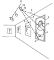
図7は、練習用又は録音用の音楽スタジオを示している。この図は、楽器、壁、天井に取り付けられたラウドスピーカタイプのトランスデューサの包括的な配置、並びにアンプリファイヤ内蔵スピーカユニット、マイク、及びマイクスタンドの配置を示している。更に、ドラムセットの近傍の位置でスタジオに組み付けられている構造体も示している。これらの構造体は、スタジオ内の音響の制御を補助するために使用される。また、この図は、スタジオ内で響く音についてアーチスト及び技術者が選択する幾つかの制御を示している。図の中央には、マイクロホン2が示されており、再位置決めデバイス8から出射された投射光線6が床に当たる位置にロケータ4を貼り付けることによって、スタジオ24におけるマイクロホン2に相対的なアドレスが割り当てられている。更に、アンプリファイヤ内蔵スピーカユニット10のトランスデューサ47の近くに配置されている他のマイクロホン2は、アンプリファイヤ内蔵スピーカユニット10上で、トランスデューサ47の近傍の再位置決めデバイス12からの投射光線6が当たる位置にロケータ4を貼り付けることによって、アンプリファイヤ内蔵スピーカユニット10に対して相対的なアドレスが割り当てられている。この場合、再位置決めデバイス12は、マイクロホンのケーブル20と一体になっている。また、図の奥の左から右にかけて、全ての楽器から遠ざけられたアーム18に取り付けられたマイクロホン2と、ピアノ16及びそのマイクロホンと、ドラムセット14並びにその音響制御パネル21及びマイクロホンとが配置されている。
FIG. 7 shows a music studio for practice or recording. This figure shows a comprehensive arrangement of instruments, loudspeaker type transducers mounted on the wall and ceiling, and an arrangement of speaker unit with built-in amplifier, microphone and microphone stand. Further, a structure assembled in the studio at a position near the drum set is also shown. These structures are used to help control the acoustics in the studio. The figure also shows some of the controls that artists and technicians select for the sound that resonates in the studio. The
スタジオの左側の壁には、音声増強型(sound reinforcement performance type)のトランスデューサ47がブラケットによって取り付けられており、天井には、周囲に筐体を有する同様のトランスデューサ47が取り付けられている。右側の壁には、通常、バックグラウンドミュージック又は放送設備システムに使用されるタイプの他のトランスデューサ47が直接的に取り付けられている。全ての用途において、全ての再位置決めデバイス又はモジュールの動作及び役割は同じであり、投射光線6がセットアップの周囲の環境の表面に当たるか、設備の他のピースに当たるかにかかわらず、ロケータを貼り付ける位置を規定することが目的である。投射光線は、再位置決めデバイスから外面に向かって投射されるので、同一平面上にない3つの投射光線及び3つのロケータを用いることで、仮想の三脚が生成され、この仮想の三脚によって、再位置決めデバイスの一意的な位置が規定され、したがって、再位置決めデバイス又はモジュールが取り付けられている物体の一意的な位置が規定される。モジュール及び物体の一意的な位置は、貼り付けられた3つのロケータに対する位置である。一実施形態では、再位置決めデバイス又はモジュールの各面のサイズは、それぞれ固有であり、光線は、光線間の各角度がそれぞれ固有になるように構成される。他の実施形態では、再位置決めデバイス又はモジュールの各面のサイズが同じであり、光線は、光線間の各角度が同じになるように構成される。
A sound reinforcement
環境及びマイクロホン2の両方に対する音源及び設備の他のピースの位置は、「サウンド」を維持するために等しく重要であるため、マイクロホン自体を正しく位置決めする場合と同じく、設備の他のピースにも再位置決めデバイスを適用して、それらの位置決めを補助する必要な場合がある。図8は、取り外し可能に取り付けられる再位置決めデバイス22がアンプリファイヤ内蔵スピーカユニット10から分解された状態を示している。再位置決めデバイス22は、増幅器内蔵スピーカユニット10に取り外し可能に取り付けることができるように適応化されている。アンプリファイヤ内蔵スピーカユニット10の一対のスロット及びこれらに対応する再位置決めデバイス22の本体の拡張部(図示せず)によって、幾度も同様に、モジュールをアンプリファイヤ内蔵スピーカユニット10に取り付けたり、ここから取り外したりすることができる。幾つもの代替となる取り外し可能な取付手段が用いられてよい。図8には、アンプリファイヤ内蔵スピーカユニット10に一体に組み込まれた再位置決めデバイス26も示されており、アンプリファイヤ内蔵スピーカユニット10の横の床面には、このモジュール26に対応するロケータ4が貼り付けられている。増幅器内蔵スピーカユニット10の正面には、再位置決めデバイス29の実施形態が示されており、再位置決めデバイス29は、ケーブルとマイクロホンを接続するように適応化された電気コネクタに一体化されている。この一体型の再位置決めデバイス29の実施形態で用いられる3つの光線の1つは、マイクロホンの指向方向に略々平行な投射方向を有し、この用途のための3つのロケータは、アンプリファイヤ内蔵スピーカユニット10に貼り付けられている。したがって、再位置決めデバイスは、第1の物体に一体的に取り付けられていると言うことができる。
The position of the sound source and the other piece of equipment relative to both the environment and the
図9は、ピアノ16に常設的に取り付けられた再位置決めデバイス26を示している。再位置決めデバイスのこの実施形態では、2つの光線のみを使用し、両方の投射光線6と、貼り付けられた両方のロケータ4とを位置合わせすることによって、ピアノ16を確実に正しく位置決めすることができる。この具体例では、使用毎にピアノ16の高さが変化することはないので、作業者がピアノ16を正しい方向に向け、したがって、180度回転させることはないと仮定すれば、6個の自由度においてピアノ16を一意的に再位置決めするために第3の光線は不要である。
FIG. 9 shows the
図10は、取り外し可能に取り付けられる再位置決めデバイス22の実施形態が取り付けられたマイクロホン2を示しており、再位置決めデバイス22は、単一の光線6を投射し、したがって、単一のロケータ4を用いてマイクロホン2を正しく位置決めしている。この場合、マイクスタンド32は、演壇に固定されているので、マイクロホン2の動きは著しく限定されており、6個の自由度のうち5個は既に定まっており、したがって、1つの投射光線のみによって、6個の全ての自由度においてマイクロホン2を完全に位置決めすることができる。
FIG. 10 shows the
図11では、3つのロケータ4がピアノ16の蓋の内側の表面に貼り付けられており、上面から見るとロケータ4の配置が隠されている。一体化された再位置決めデバイス12を用いて、ピアノ16、貼り付けられたロケータ4及びマイクロホンを揃えることによって、これらの設備のピースが組み立てられる都度、確立したサウンドを生成し、採取することができる。
In FIG. 11, three
図12に示す再位置決めデバイス23の分解斜視図は、投射方向を調整可能な光線3を有するように構成された取り外し可能に取り付けられる再位置決めデバイス23の他の実施形態を示している。摘まみネジ64を緩めることによって、光線3から投射される光線6の方向を調整できるようになる。ネジ64を締めると、ワッシャ66とモジュール23との間で光線3が固定され、調整された位置が維持される。モジュールのこの実施形態では、投射光線6の投写方向を、モジュール23自体の姿勢から独立した様々な方向に向けることができる。調整可能な光線3の方向は、モジュール23上のマーキング31と、光源3上のマーキング33とによって指定することができる。これらのマーキングを組み合わせることによって、特定の用途の間、作業者は、モジュール23に関する光線3の向きを指定することができる。モジュール23を使用する都度、モジュール23及びロケータのその特定の用途に関連する他の特定のデータと共に指定された設定を記録することによって、将来、同じセットアップを再構築することができる。
The exploded perspective view of the
投射光線6の投射方向を調整でき、ロックでき、位置を指定できるモジュール23の利点は、図13に示すように、セットアップの周囲の環境に存在する幾つかの既存の顕著な特徴の一覧からロケータを選択できる点である。選択可能な物体の既存の特徴としては、物体の角28、露出した留め具、既存の図形及びロゴ、並びに設備のハンドル及びノブ等が含まれる。光線3の調整可能な特徴、及びモジュール23自体の取り外し可能に取り付けられる特徴によって、実際のロケータを貼り付けることなく、モジュールを活用できる可能性が高まる。図13では、光線を調整可能な、一体化された再位置決めデバイス30を有するマイクロホン2の相対的配置のためのロケータとして、アンプリファイヤ内蔵スピーカユニット10の3つの角28を使用している。投射光線6は、投射方向を調整できるので、アンプリファイヤ内蔵スピーカユニット10の角28をロケータとして選択することができる。このセットアップの間、3つの光線のそれぞれの設定と共に、アンプリファイヤ内蔵スピーカユニット10の角28を選択し、ロケータとして用いたことを記録又は登録する必要があり、このデータを用いて、後に同じセットアップを再構築できる。
The advantage of the
上述のように、光線が調整可能であり、ロック可能であり、それぞれが他の光線から独立して及び再位置決めデバイス自体から独立して指定可能又は定義可能な設定を有するモジュールは、幾つの光線を用いるモジュールにも適用可能であり、物体と一体化されたモジュール、及びマウントによって取り付けられるモジュールにも適用可能である。同様に、調整可能で、ロック可能で、位置を指定可能な光線を出射するモジュールを構築する他の手段も存在する。上述した説明は、例示的なものにすぎない。 As mentioned above, a module in which the rays are adjustable and lockable, each having a configurable or definable setting independent of the other rays and independently of the repositioning device itself, can have several rays. The present invention can also be applied to a module using the above, a module integrated with an object, and a module attached by mounting. Similarly, there are other means of building a module that emits light that is adjustable, lockable and positionable. The above description is exemplary only.
図14は、取り外し可能に取り付けられる再位置決めデバイス22を拡大した分解図を示している。モジュール22は、バッテリ36と、バッテリドア38と、スイッチ40と、3つの投射光線6に分割される単一の光源と、再位置決めデバイス22をマイクロホン2に取り外し可能に取り付ける手段とを備える。取り外し可能に取り付ける手段は、ここでは、再位置決めデバイス22に設けられたマグネットノード42及びマイクロホン2の嵌合スロット44である。多くの物体があるスタジオ24内でマイクロホン2を位置決めする際に再位置決めデバイス22を容易に使用できるように、マイクロホン2には、複数の嵌合スロット44が設けられている。更に図15は、マイクロホン2とマイクケーブル46との間で使用するように適応化された再位置決めデバイスの3つの実施形態を示している。上側の実施形態では、再位置決めデバイス20は、マイクケーブル自体と一体化されている。下側の2つの実施形態では、再位置決めデバイスは、電気ケーブルアダプタ48と一体化されている。中央の実施形態はXLRタイプ電気コネクタの使用を示し、下側の実施形態はUSBタイプのコネクタの使用を示している。
FIG. 14 shows an exploded view of the
図16は、取り外し可能に取り付けられる再位置決めデバイス22の更なる実施形態を示しており、ここでは、モジュール22は、複数のマウント位置49でモジュール22を取り外し可能に取り付けることができるように適応化された電気コネクタ48に取り付けられる。マイクケーブル46は、コネクタ48の一端に取り付けられ、マイクロホン2は、コネクタ48の他端に取り付けられ、したがって、再位置決めデバイス22は、既存の如何なるマイクケーブル46及び既存の如何なるマイクロホン2にも適用することができる。この実施形態によって、多くの既存のマイクロホン及びケーブルに、光線及びロケータによる位置決め方法を適用することができる。
FIG. 16 illustrates a further embodiment of a
図17は、一体化された再位置決めデバイス52を有するように適応化されたマイククリップ50の取付を示している。更に、この再位置決めデバイス52は、マイクロホンの向きを規定するための一体化された水準器(level)54を備えている。この実施形態は、2つの投射光線6と、水準器54とを用いてマイクロホンを位置決めする再位置決めデバイス52を示している。水準器54を用いることによって、マイクロホンの位置決めに必要な光線を1つ減らすことができる。また、レベル54に代えて、錘重(plumb:図示せず)を適用してもよい。光線、バッテリ及びスイッチは、クリップに一体化され、これにより、マイクロホンをクリップに留めることによって、マイクロホンを位置決めすることができる。
FIG. 17 illustrates the attachment of a
図18は、2つの再位置決めデバイス8の構成を示しており、第1の再位置決めデバイス8は、アンプリファイヤ内蔵スピーカユニット10に一体化され、光線6を投射し、投射ドット76の位置を規定し、マイクロホン2に取り付けられた第2の再位置決めデバイス8からの投射光線6も、先に規定された投射ドット76に向けられているので、実際の常設的なロケータ4を貼り付けることなく、アンプリファイヤ内蔵スピーカユニット10に対してマイクロホン2を位置決めできる。
FIG. 18 shows the configuration of two
図19は、代替となる幾つかのロケータの種類及び配置を示している。図の中央には、スタジオ24の天井に貼り付けられたロケータ4に対してマイクロホン2が位置決めされている。天井にロケータ4を配置することによって、スタジオの床に存在する場合があるケーブル、スタンド及び散乱した物品に遮られることなく、ロケータ4にアクセスすることができる。更に図の左側には、アーム18に取り付けられたマイクロホン2がスタンドをベースとするロケータ34に対して位置決めされており、スタンド36自体は、再位置決めデバイス8と、投射光線6と、スタジオ24の床に貼り付けられたロケータ4とによって、スタジオ24内で位置決めされている。ロケータ34のこの実施形態によって、設備の他のピースのための他の投射光線6によってアクセス可能な位置にロケータ34を配置することができると共に、ロケータ34及びスタンド36は、必要に応じて移動させ、スタジオ24から取り除くことができる。同様に、図の右側に示すマイクロホン2は、スタジオ24の壁に取り付けられたロケータ34に対して位置決めされている。更に、スタジオの奥側の壁には、グリッドパターン37が描かれており、投射光線が壁に当たる位置は、これらの座標上で特定することができる。
FIG. 19 shows several alternative locator types and arrangements. In the center of the figure, the
図20は、様々なロケータを示している。時計回りに説明すると、左上は、プラスチックフィルム又は紙製の貼り付けられたロケータ4であり、次は、投射光線及びロケータの位置合わせを補助するための十字パターン68等の位置合わせシンボルを有するロケータ4である。次は、単にマーカによって塗布されたインク「X」70である。最後に、左下は、十字「X」と、バーコード72と、シリアル番号74とが記されたロケータ4である。バーコード72又はシリアル番号74は、そのロケータ4の使用に関連する詳細情報をファイルに保存するために使用される。
FIG. 20 shows various locators. Describing clockwise, the upper left is a
図21は、モジュール39が2次元画像41を投写する再位置決めデバイスの変形例を示している。モジュール39は、画像41をアンプリファイヤに投写することによって、アンプリファイヤ内蔵スピーカユニット10の正面でマイクロホン2を位置決めする。アンプリファイヤ内蔵スピーカユニット10には、ロケータ4を貼り付ける点として用いられる投写画像41の一部に3つのロケータ4が貼り付けられている。投写画像41は、ロゴ、グリッドパターン又は他の如何なる画像であってもよい。
FIG. 21 shows a modification of the repositioning device in which the
ロケータは、配置された各物体のために貼り付けられ又は選択され、物体を位置決めするために使用される投射光線毎に1つのロケータが貼り付けられるので、これは、ロケータが特定の物体の配置に割り当てられていることを意味する。ロケータは、特定の物体及び特定の投射光線に割り当てられているので、将来の使用ために、どのロケータがどの投射光線及び位置決めされるどの物体に対応しているかを示すデータを記録及び維持する必要がある。また、少数のロケータを対応する表面に貼り付け、単一の物体の配置を位置決めする場合には、記録を維持する必要がないこともある。一方、多くの物体を位置決めし、それぞれが3個の光線を使用する場合、特定のセットアップ毎に多数のロケータが使用されることになる。この場合、ノート、チャート又はログブックを用いて、複数の貼り付けられたロケータの一覧と、これらに対応するデータを管理する。更に、物体の配置が2つ以上受け入れられた場合、例えば、マイクロホンが2つの配置でいずれも良い結果を生じ、両方の配置についてロケータによるマークを付す場合、ログブックでは、物体の一覧について定められた複数の配置に関するデータを維持する必要がある。このようにして幾つかの物体を位置決めし、それぞれの物体が最大3個のロケータを使用する場合、電子データを保存する手法が有効であることは明らかである。 A locator is affixed or selected for each placed object, and one locator is affixed for each projected ray used to position the object, so that the locator is placed on a particular object It means that it is assigned to. Since locators are assigned to specific objects and specific projection rays, it is necessary to record and maintain data indicating which locators correspond to which projection rays and which objects are positioned for future use. There is. Also, if a small number of locators are affixed to the corresponding surface and the positioning of a single object is positioned, it may not be necessary to maintain a record. On the other hand, if many objects are positioned and each uses three rays, multiple locators will be used for each particular setup. In this case, a list of a plurality of pasted locators and data corresponding to them are managed using a note, a chart, or a log book. In addition, if two or more object arrangements are accepted, for example, if the microphone produces good results in both arrangements, and both arrangements are marked by a locator, the logbook defines the list of objects. It is necessary to maintain data on multiple arrangements. Obviously, if several objects are positioned in this way and each object uses a maximum of three locators, the technique of storing electronic data is effective.
更に、再位置決めデバイスと共に使用されるロケータに関して、ロケータの数が非常に多くなることがあるので、実際のロケータは、改良された照明、例えば、紫外線等の下でのみ可視になる画像を描くことができるマーカを用いて描かれた「X」印又は他の識別子であってもよい。更に、同様に紫外線光が照射された場合にのみ可視になるステッカ又は他の識別子を用いてもよい。目に見えないマーキングを用いることによって、通常の状況下では、ロケータのマークが不可視になり、意図的に紫外線光を用いた場合にのみ、ロケータを可視化することができる。 Furthermore, with respect to locators used with repositioning devices, the number of locators can be very large so that actual locators draw images that are only visible under improved illumination, such as ultraviolet light. It may be an “X” mark or other identifier drawn with a marker that can. Further, a sticker or other identifier that is visible only when irradiated with ultraviolet light may be used. By using an invisible marking, the locator mark becomes invisible under normal circumstances, and the locator can be visualized only when intentionally using ultraviolet light.
図22は、再位置決めデバイスの他の実施形態に包括的な符号80を付して示している。再位置決めデバイス80又はタンデムモジュール(tandem module)は、両端から複数の光線82を出射する。再位置決めデバイス80は、第1の物体84と第2の物体86の間に配置され、これらの2つの物体がお互いに対して再位置決めされる。図22に示すように、再位置決めデバイス8を既存の物体に対して位置決めし、これに対して第2の物体を位置決めすることができるので、物体の1つに再位置決めデバイスを取り付けることなく、2つの物体を互いに対して位置決めすることができる。実際の使用時には、再位置決めデバイスは、第1の物体84及び第2の物体86に対して配置され、ロケータ4を物体84、86に貼り付ける。そして、これらの物体を動かした後、互いに位置決めすることができる。再位置決めデバイス80は、一方の物体84上のロケータ4に光線82が当たるように再位置決めされ、次に他方の物体86が再位置決めされる。これによって、2つの物体が互いに関して再位置決めされる。
FIG. 22 shows another embodiment of a repositioning device with a
図23は、変形例である再位置決めデバイス90を示している。再位置決めデバイス90は、互いに略々直角である3つのレーザ92を備える。再位置決めデバイス90及びレーザ92は、デバイス90から3つのレーザ92が指示する物体(図示せず)までの距離を判定できる。具体的には、各レーザ92は、レーザ測定デバイスであり、このデバイスは、デバイス又は第1の物体内の各レーザから経路内の最初の障害物である第2の物体までの距離を測定できる。したがって、距離測定値を用いて、アドレスを特定することができる。更に、デバイス90は、地平に対する方向(ヨー:yaw)を判定する内部コンパスと、デバイス90の2つの方向の傾斜、すなわち、ピッチ(pitch)及びロール(roll)を判定する内部手段とを備える。例えば、デバイスは、ピッチ及びロールを判定するためにジャイロスコープを含んでいてもよい。また、加速度計を用いて、デバイス90の向きを判定してもよい。このようにして、室内のデバイスの位置を判定し、配置又は位置データを保存してもよい。デバイス90上には、複数のキー94が設けられており、これらによって、デバイス90をオン及びオフに切り換え、特定の位置についての配置データのセットを保存し及び以前に保存した配置にデバイスを再位置決めする際に配置データを確認する等、必要な動作モードを開始することができる。更に、他の実施形態に関して上述したように、位置決めデバイス90は、様々な物体に取り外し可能に取り付けることができる。
FIG. 23 shows a
図24では、位置決めデバイス90は、マイクロホン2に取り付けられており、デバイス90及び通電されたレーザ92は、スタジオ24の天井及び2つの壁からデバイス90までの距離を判定する。デバイス90は、内部的に、コンパス及びジャイロスコープによって、ヨー方向、ピッチ方向、ロール方向を判定することができる。デバイス90は、ストレージデバイスを含み、レーザ測定デバイスは、ストレージデバイスに動作可能に接続されている。また、コンパス、ジャイロスコープ、加速度計等が設けられている場合、これらもストレージデバイスに動作可能に接続される。このように、位置決めデバイス90は、その特定の配置に関連するデータを保存する機能を有し、マイクロホン2に関連する詳細情報が入力されると、デバイスは、そのスタジオ24内におけるマイクロホン2の配置を決定する全てのデータを保存する。更に、デバイス90は、その特定の配置に関連する追加的データ、例えば、日付、ユーザ名、レコーディングのファイル名等をユーザが追加できる注釈と共に保存してもよい。なお、このようなデータは、再位置決めデバイスのストレージデバイスの内部に保存してもよく、又は外部ストレージデバイス、例えば、スマートフォン、タブレット、又はコンピュータ等に保存してもよい。更に、このようなデータは、レコーディングスタジオの中央ミキシングコンソールに保存してもよい。
In FIG. 24, the
図25は、再位置決めデバイス90の特定の位置についての配置データを取得する第1のフェーズ又はステップを示している。実際の使用時には、位置決めデバイス90は、マイクロホン2に取り外し可能に取り付けられ、デバイス90及び通電されたレーザ92は、マイクロホン2の特定の配置を判定できる。そのマイクロホン2の配置に関連する詳細を含むデータは、ケーブル96を介して、既存のデータストレージデバイス94、例えば、適切なアプリケーションを実行するスマートフォン又は他の通信デバイスにダウンロードしてもよい。このように、位置決めデバイス90を用いて、図7に示すようなスタジオ内の様々な異なる楽器及び複数の異なるマイクロホンをセットアップすることができる。そして、配置データは、再位置決めデバイス90に含まれているストレージデバイスにロードされ、及び/又はスマートフォン、ハンドヘルドコンピュータ、タブレット等の外部ストレージデバイスにロードすることができる。そして、適切なアプリケーションによって、特定のスタジオセットアップに関係する全ての情報を独立したファイルに保存できる。
FIG. 25 illustrates a first phase or step of obtaining placement data for a particular position of the
図26は、マイクロホン2とマイクケーブル46との間に取り付けられるように適応化された再配置デバイス90を示している。再位置決めデバイス90を用いて、マイクロホン2を配置し、後に、以前に判定した配置又は場所において、マイクロホン2の再位置決めを確認することができる。この具体例では、その特定の配置に関連するデータは、既存のデータストレージデバイス94とデバイス90との間で、無線98によって伝送してもよい。レーザ92、内部コンパス及び内部ジャイロスコープを駆動し、デバイス90の配置が元の配置となるように探索してもよい。デバイス90は、視覚的手段又は信号100及び/又は聴覚的手段又は信号102によって、デバイス90(したがって、デバイス90が取り付けられているマイクロホン2、物体又はデバイス)が正しい配置になったことを作業者に通知する。
FIG. 26 shows a
図23〜図26に示す実施形態は、以前に説明した実施形態と同様に使用される。具体的には、再位置決めデバイス90は、デバイスからデバイスの周囲の物体までの距離を判定できるレーザと、地球磁場に関連する方向(ヨー)を判定するコンパスと、一般的にピッチ及びロールと呼ばれる2つの方向における傾斜の量を判定できるジャイロスコープとを備える。第1の物体が正しく構成されたとみなされると、第1の物体の配置は、再位置決めデバイスを第1の物体に取り付け、3つのレーザを駆動し、デバイスからレーザが指し示す3つの物体までの距離を判定し、コンパス(ヨー)の方向を判定し、デバイスのピッチ及びロールを判定することによって、第1の物体の周囲の他の物体に対して判定される。一旦、3つの距離及びデバイスの3つの回転量が判定されると、第1の物体の配置が規定される。3つの距離、ヨー、ピッチ、ロールから構成されるデータ及び第1の物体に関して特別に入力されたあらゆるデータは、デバイスに保存される。これに代えて、データは、再位置決めデバイスから独立したデータストレージデバイスにダウンロードしてもよい。再位置決めデバイスから独立したデバイスでデータを収集する場合、デバイス間のデータの通信は、マイクケーブルのシールドラインを含む有線接続で行ってもよく、ブルートゥース又は他の無線規格等の無線接続で行ってもよい。一実施形態においては、ピッチ、ロール、ヨー、及びレーザが測定した距離データは、再位置決めデバイス(モジュール)によって収集、処理及び保存され、他の実施形態では、これらのデータは、独立した有線又は無線デバイスによって処理及び保存される。
The embodiment shown in FIGS. 23-26 is used similarly to the previously described embodiment. Specifically, the
次に、第2のフェーズ又はステップにおいて、再位置決めデバイス90が再位置決めされ、これによって、物体の正しい位置が確認される。再位置決めデバイス90は、第1の物体に貼り付けられ、又は取り外し可能に取り付けられ、又は一体に形成され、再位置決めデバイス90のレーザ、コンパス、及びジャイロスコープが駆動され、レーザ距離、ヨー、ピッチ、及びロールが初期フェーズからの設定に一致するまでデバイスの配置が調整され、これによって、物体の再位置決めが成功する。この方法の最初の位置決め又は配置のフェーズ又はステップの間に取得されたデータに対して物体を再位置決めする場合、デバイスは、様々な視覚的又は聴覚的なインジケータを用いて、物体が正確な位置に戻った時点を正確に指示してもよい。視覚的なインジケータは、例えば、アナログメータ、ライトバーメータ、デジタルLCDメータ、形状の転換、色の転換、又は物体が正確な位置に戻った正確な時点を表す所定の値に転換される数値表現の変化等であってもよい。聴覚的なインジケータは、例えば、物体が正確な位置に戻った正確な時点を表す所定の音、ピッチ又は音の強さに転換される言語、音声、ピッチ又は音の強さを含む音の変化であってもよい。包括的に言えば、ここに説明したシステムは、再位置決めデバイス及びその使用方法に関するものである。必要に応じて、再位置決めデバイスの実施形態及びその使用方法を開示した。但し、開示した実施形態は、例示的なものにすぎず、再位置決めデバイスは、他の様々な形式で実施できることは明らかである。図は、実際の縮尺を反映しておらず、特定の要素の詳細を示すために幾つかの特徴を誇張又は矮小化していることがあり、また、新規な側面を不明瞭にしないために、関連する要素を省略していることもある。したがって、ここに開示した特定の構造的及び機能的な詳細は、限定的なものとは解釈されず、特許請求の範囲の基礎及び当業者が再位置決めデバイスを様々に実施するための代表的な基礎としてのみ解釈される。例示した実施形態は、限定ではなく開示を目的として、再位置決めデバイス及びその使用方法を示している。
Next, in a second phase or step, the
ここで使用する「備える」及び「備えた」という用語は、排他的ではなく包括的な意味で解釈される。具体的には、この明細書及び特許請求の範囲で使用する「備える」及び「備えた」という用語及びその活用形は、特定の特徴、ステップ又は部品が含まれることを意味する。この用語は、他の特徴、ステップ又は部品の存在を排除するものではない。 As used herein, the terms “comprising” and “comprising” are to be interpreted in an inclusive rather than exclusive sense. Specifically, as used in this specification and claims, the terms “comprising” and “comprising” and their conjugations mean that a particular feature, step or part is included. The term does not exclude the presence of other features, steps or parts.
また、物体Aが物体Bに動作可能に接続されている場合の「動作可能に接続される」という表現は、物体Aが物体Bに直接的に接続される場合と、1つ以上の物体がこれらの間に介在している場合の両方を意味する。 In addition, the expression “operably connected” in the case where the object A is operably connected to the object B includes the case where the object A is directly connected to the object B and one or more objects It means both of the cases that are interposed between them.
図23は、変形例である再位置決めデバイス90を示している。再位置決めデバイス90は、互いに略々直角である3つのレーザ92を備える。再位置決めデバイス90及びレーザ92は、デバイス90から3つのレーザ92が指示する物体(図示せず)までの距離を判定できる。具体的には、各レーザ92は、レーザ測定デバイスであり、このデバイスは、デバイス又は第1の物体内の各レーザから経路内の最初の障害物である第2の物体までの距離を測定できる。したがって、距離測定値を用いて、アドレスを特定することができる。更に、デバイス90は、地平に対する方向(ヨー:yaw)を判定する内部コンパスと、デバイス90の2つの方向の傾斜、すなわち、ピッチ(pitch)及びロール(roll)を判定する内部手段とを備える。例えば、デバイスは、ピッチ及びロールを判定するためにジャイロスコープを含んでいてもよい。また、加速度計を用いて、デバイス90の向きを判定してもよい。このようにして、室内のデバイスの位置を判定し、配置又は位置データを保存してもよい。デバイス90上には、複数のキー91が設けられており、これらによって、デバイス90をオン及びオフに切り換え、特定の位置についての配置データのセットを保存し及び以前に保存した配置にデバイスを再位置決めする際に配置データを確認する等、必要な動作モードを開始することができる。更に、他の実施形態に関して上述したように、位置決めデバイス90は、様々な物体に取り外し可能に取り付けることができる。
FIG. 23 shows a
Claims (71)
前記第1の物体に動作可能に接続され、それぞれが前記第2の物体に関連するビーム位置決め点を定める少なくとも2つの光線を生成する少なくとも1つの光源と、
前記少なくとも1つの光源に動作可能に接続された電源と、
前記ビーム位置決め点を規定する手段とを備える再位置決めデバイス。 In a repositioning device for positioning and repositioning a first object relative to a second object,
At least one light source operatively connected to the first object and generating at least two rays each defining a beam positioning point associated with the second object;
A power source operably connected to the at least one light source;
Repositioning device comprising means for defining said beam positioning point.
第1の物体を第2の物体に対して位置決めし、設定位置を定めるステップであって、前記第1の物体は、それぞれが前記第2の物体に関連するビーム位置決め点を規定する少なくとも2つの光線を生成する少なくとも1つの光源と、前記少なくとも1つの光源に動作可能に接続された電源と、前記ビーム位置決め点を規定する手段とを備える再位置決めデバイスに対して位置決めされるステップと、
前記各ビーム位置決め点に関して前記第2の物体に対する位置決め点を規定するステップと、
前記第1の物体及び第2の物体の少なくとも1つを移動させるステップと、
前記各ビーム位置決め点がビーム位置決め点に一致するように前記第1の物体を前記第2の物体に対して移動させるステップとを有する方法。 In a method for positioning and repositioning a first object relative to a second object,
Positioning a first object relative to a second object and determining a set position, wherein the first object includes at least two beam positioning points each associated with the second object Positioned with respect to a repositioning device comprising at least one light source for generating a light beam, a power source operably connected to the at least one light source, and means for defining the beam positioning point;
Defining a positioning point for the second object with respect to each beam positioning point;
Moving at least one of the first object and the second object;
Moving the first object relative to the second object such that each beam positioning point coincides with a beam positioning point.
Applications Claiming Priority (3)
| Application Number | Priority Date | Filing Date | Title |
|---|---|---|---|
| US13/327,540 US8991062B2 (en) | 2011-12-15 | 2011-12-15 | Locating and relocating device |
| US13/327,540 | 2011-12-15 | ||
| PCT/CA2012/050898 WO2013086635A1 (en) | 2011-12-15 | 2012-12-14 | Locating and relocating device |
Publications (2)
| Publication Number | Publication Date |
|---|---|
| JP2015507178A true JP2015507178A (en) | 2015-03-05 |
| JP6041891B2 JP6041891B2 (en) | 2016-12-14 |
Family
ID=48609830
Family Applications (1)
| Application Number | Title | Priority Date | Filing Date |
|---|---|---|---|
| JP2014546254A Active JP6041891B2 (en) | 2011-12-15 | 2012-12-14 | Positioning and repositioning device |
Country Status (21)
| Country | Link |
|---|---|
| US (2) | US8991062B2 (en) |
| EP (1) | EP2791696B1 (en) |
| JP (1) | JP6041891B2 (en) |
| KR (1) | KR20140111675A (en) |
| CN (1) | CN104169735B (en) |
| AU (1) | AU2012330501A1 (en) |
| BR (1) | BR112014014574B1 (en) |
| CA (1) | CA2871497C (en) |
| ES (1) | ES2935757T3 (en) |
| FI (1) | FI2791696T3 (en) |
| HK (1) | HK1203630A1 (en) |
| IL (1) | IL233126A0 (en) |
| IN (1) | IN2014MN01429A (en) |
| MX (1) | MX349474B (en) |
| PH (1) | PH12014501627A1 (en) |
| PL (1) | PL2791696T3 (en) |
| RU (1) | RU2601229C2 (en) |
| SG (1) | SG11201403221WA (en) |
| TW (1) | TWI597514B (en) |
| WO (1) | WO2013086635A1 (en) |
| ZA (1) | ZA201405120B (en) |
Cited By (1)
| Publication number | Priority date | Publication date | Assignee | Title |
|---|---|---|---|---|
| JP6996021B1 (en) * | 2021-08-30 | 2022-01-17 | 文彦 藤田 | Equatorial mount polar alignment support device |
Families Citing this family (16)
| Publication number | Priority date | Publication date | Assignee | Title |
|---|---|---|---|---|
| US8991062B2 (en) * | 2011-12-15 | 2015-03-31 | Atkinson Audio Inc. | Locating and relocating device |
| US9303863B2 (en) * | 2013-12-12 | 2016-04-05 | Shure Acquisition Holdings, Inc. | Integrated light and microphone system |
| CN103900535B (en) * | 2014-03-10 | 2016-04-20 | 天津大学 | Towards camera 4 method for relocating that historical relic subtle change detects |
| IL233145A (en) * | 2014-06-15 | 2015-10-29 | Cct Creative Construction Tools Ltd | Method and apparatus for assisting in tiling |
| JP6307366B2 (en) * | 2014-06-25 | 2018-04-04 | 株式会社ミライト | Orientation marking stand and orientation marking device |
| WO2016135198A1 (en) * | 2015-02-26 | 2016-09-01 | Brüel & Kjær Sound & Vibration Measurement A/S | Method of detecting a spatial orientation of a transducer by one or more spatial orientation features |
| JP6715938B2 (en) * | 2016-01-26 | 2020-07-01 | チュビタック (ターキー ビリムセル ヴィ テクノロジク アラスティルマ クルム)Tubitak (Turkiye Bilimsel Ve Teknolojik Arastirma Kurumu) | 2-channel laser audio monitoring system |
| FR3048518A1 (en) * | 2016-03-02 | 2017-09-08 | Aldebaran Robotics | METHOD FOR POSITIONING AN OBJECT ON A SUPPORT |
| US10538927B1 (en) * | 2016-03-25 | 2020-01-21 | David M. Keller | Construction template with laser target device and method of use |
| US11415264B2 (en) * | 2019-03-28 | 2022-08-16 | Karl Storz Endoscopy-America, Inc. | Bracket assembly and method for mounting electrical equipment in between a monitor and a supporting structure |
| US11193766B2 (en) * | 2019-04-09 | 2021-12-07 | Ruslan Pozhidayev | Apparatus and methods in installation of objects |
| CN113048878B (en) * | 2019-12-27 | 2023-08-29 | 苏州因确匹电子科技有限公司 | Optical positioning system and method and multi-view three-dimensional reconstruction system and method |
| TWI751003B (en) * | 2021-01-22 | 2021-12-21 | 友達光電股份有限公司 | Light source positioning method and system |
| WO2022192155A1 (en) * | 2021-03-10 | 2022-09-15 | Rosendin Electric, Inc. | Downlight laser jig |
| CN112927269B (en) * | 2021-03-26 | 2024-07-16 | 深圳市无限动力发展有限公司 | Map construction method and device based on environment semantics and computer equipment |
| KR102633395B1 (en) * | 2022-04-18 | 2024-02-06 | 경상국립대학교산학협력단 | Method for emitting a quadrat-shaped optical signal and an optical signal emitting device supporting the same |
Citations (3)
| Publication number | Priority date | Publication date | Assignee | Title |
|---|---|---|---|---|
| JPH085320A (en) * | 1993-12-29 | 1996-01-12 | Rautaruukki Oy | Method for determining position of measuring instrument, which radiates and receives light for measuring lining abrasion of container |
| JP2009005078A (en) * | 2007-06-21 | 2009-01-08 | Nippon Hoso Kyokai <Nhk> | Device for installing and adjusting speaker |
| JP2011516857A (en) * | 2008-04-02 | 2011-05-26 | イーストマン コダック カンパニー | Measuring the distance and orientation of objects |
Family Cites Families (41)
| Publication number | Priority date | Publication date | Assignee | Title |
|---|---|---|---|---|
| US3489495A (en) | 1967-03-21 | 1970-01-13 | Singer General Precision | Range finding instruments |
| US4813774A (en) | 1982-08-27 | 1989-03-21 | Raytheon Company | Skewed rhombus ring laser gyro |
| US4621926A (en) * | 1985-04-30 | 1986-11-11 | Lasercon Corporation | Interferometer system for controlling non-rectilinear movement of an object |
| GB2180117B (en) * | 1985-09-05 | 1989-09-06 | Ferranti Plc | Three-dimensional position measuring apparatus |
| US4709580A (en) | 1986-02-26 | 1987-12-01 | Bd Systems, Inc. | Retroflective attitude determining system |
| AU628301B2 (en) | 1987-09-30 | 1992-09-17 | Kabushiki Kaisha Komatsu Seisakusho | Position meter using laser beam |
| US5046259A (en) * | 1990-05-14 | 1991-09-10 | Harbor Branch Oceanographic Institution, Inc. | Underwater measuring systems and methods |
| US5059789A (en) * | 1990-10-22 | 1991-10-22 | International Business Machines Corp. | Optical position and orientation sensor |
| JP2953371B2 (en) * | 1996-02-05 | 1999-09-27 | 日本電気株式会社 | Positioning device for projector installation |
| US5767960A (en) | 1996-06-14 | 1998-06-16 | Ascension Technology Corporation | Optical 6D measurement system with three fan-shaped beams rotating around one axis |
| JPH10318751A (en) * | 1997-05-20 | 1998-12-04 | Nikon Corp | Remotely controllable laser beam projection device |
| FR2764992B1 (en) | 1997-06-24 | 1999-09-03 | Romain Granger | DEVICE FOR POSITIONALLY LOCATING AN OBJECT IN SPACE AND METHOD OF USING THE DEVICE |
| GB9810405D0 (en) | 1998-05-15 | 1998-07-15 | Measurement Devices Ltd | Survey apparatus |
| JP2000186952A (en) * | 1998-12-22 | 2000-07-04 | Atsushi Tominaga | Liquid level detector |
| US6417839B1 (en) | 1999-05-20 | 2002-07-09 | Ascension Technology Corporation | System for position and orientation determination of a point in space using scanning laser beams |
| JP3798188B2 (en) | 1999-06-28 | 2006-07-19 | 株式会社小糸製作所 | Shape change measuring device |
| US6301997B1 (en) * | 2000-09-11 | 2001-10-16 | Gregory A. Welte | Positioning device for power-driven fastener |
| US6891148B1 (en) * | 2002-02-25 | 2005-05-10 | The United States Of America As Represented By The Administrator Of The National Aeronatics And Space Administration | Scaling device for photographic images |
| JP2004060402A (en) * | 2002-07-31 | 2004-02-26 | Develo:Kk | Laser marking system and steel pipe driving method |
| DE10242749A1 (en) | 2002-09-13 | 2004-04-08 | Bergische Universität Wuppertal | 3D interferometric position measurement system, e.g. for use in locating the probe of a raster scanning microscope, whereby a measurement area is created by the interference of at least three coherent waves |
| US6895677B2 (en) * | 2002-12-16 | 2005-05-24 | First Down Laser Systems, Llc | System for operating one or more lasers to project a visible line onto a surface |
| US7219438B2 (en) * | 2002-12-16 | 2007-05-22 | First Down Laser, Llc. | System for operating one or more suspended laser projectors to project a temporary visible image onto a surface |
| US7200946B2 (en) * | 2003-07-28 | 2007-04-10 | Ritenour Ernest C | Alignment apparatus |
| US7040780B2 (en) * | 2004-02-20 | 2006-05-09 | General Dynamics Armament And Technical Products | Laser dazzler matrix |
| US7003890B2 (en) * | 2004-06-14 | 2006-02-28 | Kavounas Gregory T | Wall reflectors for aligning laser beams and methods of using them |
| US7219437B2 (en) * | 2005-01-28 | 2007-05-22 | Brent Dallman | Laser guided work device |
| TWM283169U (en) * | 2005-06-21 | 2005-12-11 | Quarton Inc | Multi-beam laser level |
| JP4754298B2 (en) * | 2005-08-17 | 2011-08-24 | 鹿島建設株式会社 | Three-dimensional coordinate determination method, inking method and positioning method using laser light |
| JP2008204196A (en) * | 2007-02-20 | 2008-09-04 | Osaka Univ | Information input system |
| US7621053B2 (en) * | 2007-04-13 | 2009-11-24 | Virtek Vision International Inc. | Assembly apparatus |
| US8104186B2 (en) * | 2007-05-07 | 2012-01-31 | Michael Raschella | Method and system for projecting an aiming X-shaped mark on a target |
| US7614154B2 (en) * | 2007-10-26 | 2009-11-10 | The Boeing Company | System and method for locating components of a structure |
| US7665223B2 (en) * | 2008-06-20 | 2010-02-23 | Delta Ii, I.P., Trust | Measuring device with extensible cord and method |
| US7908750B2 (en) * | 2008-10-01 | 2011-03-22 | Sharon Ree Goick | System and method for decorating cakes and confections |
| CN102292646B (en) * | 2009-01-20 | 2014-03-12 | 皇家飞利浦电子股份有限公司 | Method for adjusting self mixing laser sensor system for measuring velocity of vehicle |
| US7984557B1 (en) * | 2009-06-05 | 2011-07-26 | Carl Keith D | Laser-guided positioning device |
| US8087176B1 (en) * | 2010-06-28 | 2012-01-03 | Trimble Navigation Ltd | Two dimension layout and point transfer system |
| EP2453205A1 (en) * | 2010-11-11 | 2012-05-16 | Leica Geosystems AG | Construction and measuring device for measuring and marking points along contour lines running horizontally across a surface |
| US8567077B2 (en) * | 2011-10-20 | 2013-10-29 | Raytheon Company | Laser tracker system and technique for antenna boresight alignment |
| US8991062B2 (en) * | 2011-12-15 | 2015-03-31 | Atkinson Audio Inc. | Locating and relocating device |
| US8756822B2 (en) * | 2012-04-06 | 2014-06-24 | Robert A. Rabiner | Systems and methods for sailboat mast alignment |
-
2011
- 2011-12-15 US US13/327,540 patent/US8991062B2/en active Active
-
2012
- 2012-12-14 CA CA2871497A patent/CA2871497C/en active Active
- 2012-12-14 CN CN201280069577.7A patent/CN104169735B/en active Active
- 2012-12-14 JP JP2014546254A patent/JP6041891B2/en active Active
- 2012-12-14 MX MX2014007186A patent/MX349474B/en active IP Right Grant
- 2012-12-14 PL PL12858524.7T patent/PL2791696T3/en unknown
- 2012-12-14 TW TW101147538A patent/TWI597514B/en active
- 2012-12-14 WO PCT/CA2012/050898 patent/WO2013086635A1/en active Application Filing
- 2012-12-14 AU AU2012330501A patent/AU2012330501A1/en not_active Abandoned
- 2012-12-14 ES ES12858524T patent/ES2935757T3/en active Active
- 2012-12-14 BR BR112014014574-1A patent/BR112014014574B1/en active IP Right Grant
- 2012-12-14 FI FIEP12858524.7T patent/FI2791696T3/en active
- 2012-12-14 RU RU2014124323/28A patent/RU2601229C2/en active
- 2012-12-14 US US14/365,970 patent/US9322641B2/en active Active
- 2012-12-14 EP EP12858524.7A patent/EP2791696B1/en active Active
- 2012-12-14 IN IN1429MUN2014 patent/IN2014MN01429A/en unknown
- 2012-12-14 SG SG11201403221WA patent/SG11201403221WA/en unknown
- 2012-12-14 KR KR1020147019255A patent/KR20140111675A/en not_active Application Discontinuation
-
2014
- 2014-06-15 IL IL233126A patent/IL233126A0/en unknown
- 2014-07-14 ZA ZA2014/05120A patent/ZA201405120B/en unknown
- 2014-07-15 PH PH12014501627A patent/PH12014501627A1/en unknown
-
2015
- 2015-04-22 HK HK15103898.0A patent/HK1203630A1/en unknown
Patent Citations (3)
| Publication number | Priority date | Publication date | Assignee | Title |
|---|---|---|---|---|
| JPH085320A (en) * | 1993-12-29 | 1996-01-12 | Rautaruukki Oy | Method for determining position of measuring instrument, which radiates and receives light for measuring lining abrasion of container |
| JP2009005078A (en) * | 2007-06-21 | 2009-01-08 | Nippon Hoso Kyokai <Nhk> | Device for installing and adjusting speaker |
| JP2011516857A (en) * | 2008-04-02 | 2011-05-26 | イーストマン コダック カンパニー | Measuring the distance and orientation of objects |
Cited By (1)
| Publication number | Priority date | Publication date | Assignee | Title |
|---|---|---|---|---|
| JP6996021B1 (en) * | 2021-08-30 | 2022-01-17 | 文彦 藤田 | Equatorial mount polar alignment support device |
Also Published As
Similar Documents
| Publication | Publication Date | Title |
|---|---|---|
| JP6041891B2 (en) | Positioning and repositioning device | |
| US11802764B2 (en) | Point layout system using single laser transmitter | |
| US8942395B2 (en) | Pointing element enhanced speaker system | |
| US7487598B2 (en) | Method, system and scale for the determination and/or simulation of proportions | |
| CN102150018A (en) | Conductor centric electronic music stand system | |
| WO2008073953A2 (en) | Laser inclinometer audio direction | |
| KR101462834B1 (en) | Building model having bottom display unit | |
| TWI614388B (en) | Position pointer | |
| AU2015249163B2 (en) | Locating and relocating device | |
| NZ626932B2 (en) | Locating and relocating device | |
| JP2008048226A (en) | Projector adjustment system and projector adjusting program | |
| KR101871958B1 (en) | Laser guide apparatus and method for measuring distance and degree using the same | |
| CN213458508U (en) | Interactive equipment suitable for science popularization vehicle part knowledge | |
| ES2955770T3 (en) | Display layout | |
| US20230122747A1 (en) | Musical device and associated method | |
| CN107576998A (en) | Human tracking system applied to interactive digital exhibition | |
| CN219590511U (en) | Portable laser range unit | |
| CN212255734U (en) | Multifunctional wall detector | |
| TWI440819B (en) | Portable electronic device and method of measuring the length of an object | |
| TWM506281U (en) | Measurement apparatus |
Legal Events
| Date | Code | Title | Description |
|---|---|---|---|
| RD01 | Notification of change of attorney |
Free format text: JAPANESE INTERMEDIATE CODE: A7426 Effective date: 20141212 |
|
| A521 | Request for written amendment filed |
Free format text: JAPANESE INTERMEDIATE CODE: A821 Effective date: 20141212 |
|
| A621 | Written request for application examination |
Free format text: JAPANESE INTERMEDIATE CODE: A621 Effective date: 20151214 |
|
| A871 | Explanation of circumstances concerning accelerated examination |
Free format text: JAPANESE INTERMEDIATE CODE: A871 Effective date: 20151214 |
|
| A975 | Report on accelerated examination |
Free format text: JAPANESE INTERMEDIATE CODE: A971005 Effective date: 20160308 |
|
| A131 | Notification of reasons for refusal |
Free format text: JAPANESE INTERMEDIATE CODE: A131 Effective date: 20160315 |
|
| A601 | Written request for extension of time |
Free format text: JAPANESE INTERMEDIATE CODE: A601 Effective date: 20160609 |
|
| A521 | Request for written amendment filed |
Free format text: JAPANESE INTERMEDIATE CODE: A523 Effective date: 20160915 |
|
| TRDD | Decision of grant or rejection written | ||
| A01 | Written decision to grant a patent or to grant a registration (utility model) |
Free format text: JAPANESE INTERMEDIATE CODE: A01 Effective date: 20161011 |
|
| A61 | First payment of annual fees (during grant procedure) |
Free format text: JAPANESE INTERMEDIATE CODE: A61 Effective date: 20161108 |
|
| R150 | Certificate of patent or registration of utility model |
Ref document number: 6041891 Country of ref document: JP Free format text: JAPANESE INTERMEDIATE CODE: R150 |
|
| R250 | Receipt of annual fees |
Free format text: JAPANESE INTERMEDIATE CODE: R250 |
|
| R250 | Receipt of annual fees |
Free format text: JAPANESE INTERMEDIATE CODE: R250 |
|
| R250 | Receipt of annual fees |
Free format text: JAPANESE INTERMEDIATE CODE: R250 |
|
| R250 | Receipt of annual fees |
Free format text: JAPANESE INTERMEDIATE CODE: R250 |
|
| R250 | Receipt of annual fees |
Free format text: JAPANESE INTERMEDIATE CODE: R250 |