JP2015500033A - Continuous perfusion filtration equipment - Google Patents
Continuous perfusion filtration equipment Download PDFInfo
- Publication number
- JP2015500033A JP2015500033A JP2014546134A JP2014546134A JP2015500033A JP 2015500033 A JP2015500033 A JP 2015500033A JP 2014546134 A JP2014546134 A JP 2014546134A JP 2014546134 A JP2014546134 A JP 2014546134A JP 2015500033 A JP2015500033 A JP 2015500033A
- Authority
- JP
- Japan
- Prior art keywords
- liquid
- filter
- container
- stirrer
- shaft
- Prior art date
- Legal status (The legal status is an assumption and is not a legal conclusion. Google has not performed a legal analysis and makes no representation as to the accuracy of the status listed.)
- Pending
Links
- XCPOYTOLZNSCHC-UHFFFAOYSA-N CCC1(CCCC1)[U] Chemical compound CCC1(CCCC1)[U] XCPOYTOLZNSCHC-UHFFFAOYSA-N 0.000 description 1
Images


Classifications
-
- C—CHEMISTRY; METALLURGY
- C12—BIOCHEMISTRY; BEER; SPIRITS; WINE; VINEGAR; MICROBIOLOGY; ENZYMOLOGY; MUTATION OR GENETIC ENGINEERING
- C12M—APPARATUS FOR ENZYMOLOGY OR MICROBIOLOGY; APPARATUS FOR CULTURING MICROORGANISMS FOR PRODUCING BIOMASS, FOR GROWING CELLS OR FOR OBTAINING FERMENTATION OR METABOLIC PRODUCTS, i.e. BIOREACTORS OR FERMENTERS
- C12M29/00—Means for introduction, extraction or recirculation of materials, e.g. pumps
- C12M29/04—Filters; Permeable or porous membranes or plates, e.g. dialysis
-
- B—PERFORMING OPERATIONS; TRANSPORTING
- B01—PHYSICAL OR CHEMICAL PROCESSES OR APPARATUS IN GENERAL
- B01F—MIXING, e.g. DISSOLVING, EMULSIFYING OR DISPERSING
- B01F27/00—Mixers with rotary stirring devices in fixed receptacles; Kneaders
- B01F27/05—Stirrers
- B01F27/051—Stirrers characterised by their elements, materials or mechanical properties
- B01F27/054—Deformable stirrers, e.g. deformed by a centrifugal force applied during operation
-
- B—PERFORMING OPERATIONS; TRANSPORTING
- B01—PHYSICAL OR CHEMICAL PROCESSES OR APPARATUS IN GENERAL
- B01F—MIXING, e.g. DISSOLVING, EMULSIFYING OR DISPERSING
- B01F27/00—Mixers with rotary stirring devices in fixed receptacles; Kneaders
- B01F27/05—Stirrers
- B01F27/11—Stirrers characterised by the configuration of the stirrers
- B01F27/19—Stirrers with two or more mixing elements mounted in sequence on the same axis
- B01F27/191—Stirrers with two or more mixing elements mounted in sequence on the same axis with similar elements
-
- B—PERFORMING OPERATIONS; TRANSPORTING
- B01—PHYSICAL OR CHEMICAL PROCESSES OR APPARATUS IN GENERAL
- B01F—MIXING, e.g. DISSOLVING, EMULSIFYING OR DISPERSING
- B01F27/00—Mixers with rotary stirring devices in fixed receptacles; Kneaders
- B01F27/80—Mixers with rotary stirring devices in fixed receptacles; Kneaders with stirrers rotating about a substantially vertical axis
- B01F27/91—Mixers with rotary stirring devices in fixed receptacles; Kneaders with stirrers rotating about a substantially vertical axis with propellers
-
- B—PERFORMING OPERATIONS; TRANSPORTING
- B01—PHYSICAL OR CHEMICAL PROCESSES OR APPARATUS IN GENERAL
- B01F—MIXING, e.g. DISSOLVING, EMULSIFYING OR DISPERSING
- B01F31/00—Mixers with shaking, oscillating, or vibrating mechanisms
- B01F31/42—Mixers with shaking, oscillating, or vibrating mechanisms with pendulum stirrers, i.e. with stirrers suspended so as to oscillate about fixed points or axes
-
- B—PERFORMING OPERATIONS; TRANSPORTING
- B01—PHYSICAL OR CHEMICAL PROCESSES OR APPARATUS IN GENERAL
- B01F—MIXING, e.g. DISSOLVING, EMULSIFYING OR DISPERSING
- B01F31/00—Mixers with shaking, oscillating, or vibrating mechanisms
- B01F31/44—Mixers with shaking, oscillating, or vibrating mechanisms with stirrers performing an oscillatory, vibratory or shaking movement
- B01F31/445—Mixers with shaking, oscillating, or vibrating mechanisms with stirrers performing an oscillatory, vibratory or shaking movement performing an oscillatory movement about an axis
-
- B—PERFORMING OPERATIONS; TRANSPORTING
- B01—PHYSICAL OR CHEMICAL PROCESSES OR APPARATUS IN GENERAL
- B01F—MIXING, e.g. DISSOLVING, EMULSIFYING OR DISPERSING
- B01F33/00—Other mixers; Mixing plants; Combinations of mixers
- B01F33/45—Magnetic mixers; Mixers with magnetically driven stirrers
- B01F33/453—Magnetic mixers; Mixers with magnetically driven stirrers using supported or suspended stirring elements
- B01F33/4534—Magnetic mixers; Mixers with magnetically driven stirrers using supported or suspended stirring elements using a rod for supporting the stirring element, e.g. stirrer sliding on a rod or mounted on a rod sliding in a tube
-
- B—PERFORMING OPERATIONS; TRANSPORTING
- B01—PHYSICAL OR CHEMICAL PROCESSES OR APPARATUS IN GENERAL
- B01F—MIXING, e.g. DISSOLVING, EMULSIFYING OR DISPERSING
- B01F35/00—Accessories for mixers; Auxiliary operations or auxiliary devices; Parts or details of general application
- B01F35/50—Mixing receptacles
- B01F35/513—Flexible receptacles, e.g. bags supported by rigid containers
-
- C—CHEMISTRY; METALLURGY
- C12—BIOCHEMISTRY; BEER; SPIRITS; WINE; VINEGAR; MICROBIOLOGY; ENZYMOLOGY; MUTATION OR GENETIC ENGINEERING
- C12M—APPARATUS FOR ENZYMOLOGY OR MICROBIOLOGY; APPARATUS FOR CULTURING MICROORGANISMS FOR PRODUCING BIOMASS, FOR GROWING CELLS OR FOR OBTAINING FERMENTATION OR METABOLIC PRODUCTS, i.e. BIOREACTORS OR FERMENTERS
- C12M23/00—Constructional details, e.g. recesses, hinges
- C12M23/02—Form or structure of the vessel
- C12M23/14—Bags
-
- C—CHEMISTRY; METALLURGY
- C12—BIOCHEMISTRY; BEER; SPIRITS; WINE; VINEGAR; MICROBIOLOGY; ENZYMOLOGY; MUTATION OR GENETIC ENGINEERING
- C12M—APPARATUS FOR ENZYMOLOGY OR MICROBIOLOGY; APPARATUS FOR CULTURING MICROORGANISMS FOR PRODUCING BIOMASS, FOR GROWING CELLS OR FOR OBTAINING FERMENTATION OR METABOLIC PRODUCTS, i.e. BIOREACTORS OR FERMENTERS
- C12M23/00—Constructional details, e.g. recesses, hinges
- C12M23/26—Constructional details, e.g. recesses, hinges flexible
-
- C—CHEMISTRY; METALLURGY
- C12—BIOCHEMISTRY; BEER; SPIRITS; WINE; VINEGAR; MICROBIOLOGY; ENZYMOLOGY; MUTATION OR GENETIC ENGINEERING
- C12M—APPARATUS FOR ENZYMOLOGY OR MICROBIOLOGY; APPARATUS FOR CULTURING MICROORGANISMS FOR PRODUCING BIOMASS, FOR GROWING CELLS OR FOR OBTAINING FERMENTATION OR METABOLIC PRODUCTS, i.e. BIOREACTORS OR FERMENTERS
- C12M23/00—Constructional details, e.g. recesses, hinges
- C12M23/28—Constructional details, e.g. recesses, hinges disposable or single use
-
- C—CHEMISTRY; METALLURGY
- C12—BIOCHEMISTRY; BEER; SPIRITS; WINE; VINEGAR; MICROBIOLOGY; ENZYMOLOGY; MUTATION OR GENETIC ENGINEERING
- C12M—APPARATUS FOR ENZYMOLOGY OR MICROBIOLOGY; APPARATUS FOR CULTURING MICROORGANISMS FOR PRODUCING BIOMASS, FOR GROWING CELLS OR FOR OBTAINING FERMENTATION OR METABOLIC PRODUCTS, i.e. BIOREACTORS OR FERMENTERS
- C12M27/00—Means for mixing, agitating or circulating fluids in the vessel
- C12M27/02—Stirrer or mobile mixing elements
- C12M27/06—Stirrer or mobile mixing elements with horizontal or inclined stirrer shaft or axis
-
- C—CHEMISTRY; METALLURGY
- C12—BIOCHEMISTRY; BEER; SPIRITS; WINE; VINEGAR; MICROBIOLOGY; ENZYMOLOGY; MUTATION OR GENETIC ENGINEERING
- C12M—APPARATUS FOR ENZYMOLOGY OR MICROBIOLOGY; APPARATUS FOR CULTURING MICROORGANISMS FOR PRODUCING BIOMASS, FOR GROWING CELLS OR FOR OBTAINING FERMENTATION OR METABOLIC PRODUCTS, i.e. BIOREACTORS OR FERMENTERS
- C12M29/00—Means for introduction, extraction or recirculation of materials, e.g. pumps
- C12M29/06—Nozzles; Sprayers; Spargers; Diffusers
Landscapes
- Chemical & Material Sciences (AREA)
- Health & Medical Sciences (AREA)
- Zoology (AREA)
- Life Sciences & Earth Sciences (AREA)
- Engineering & Computer Science (AREA)
- Bioinformatics & Cheminformatics (AREA)
- Organic Chemistry (AREA)
- Wood Science & Technology (AREA)
- Chemical Kinetics & Catalysis (AREA)
- Biomedical Technology (AREA)
- Sustainable Development (AREA)
- Biochemistry (AREA)
- General Engineering & Computer Science (AREA)
- General Health & Medical Sciences (AREA)
- Genetics & Genomics (AREA)
- Microbiology (AREA)
- Biotechnology (AREA)
- Clinical Laboratory Science (AREA)
- Apparatus Associated With Microorganisms And Enzymes (AREA)
Abstract
【構成】本発明の一つの態様による液体を使用するバイオプロセシング装置は、この液体を収容する少なくとも一部が可撓性を示す容器、および上記液体内を移動できるフィルターからなる。液体を撹拌する撹拌機を設けてもよく、この撹拌機はミキサーに接続することができる。ミキサーは回転軸線を中心にして回転してもよく、あるいは回転しなくてもよい。【選択図】図1A bioprocessing apparatus using a liquid according to one embodiment of the present invention comprises a container in which at least a part of the liquid is accommodated and a filter capable of moving in the liquid. A stirrer for stirring the liquid may be provided, and this stirrer can be connected to a mixer. The mixer may or may not rotate about the axis of rotation. [Selection] Figure 1
Description
本出願は、米国仮特許出願第61/568,872号の優先権を主張する出願であり、この仮特許出願の内容を援用する出願である。 This application claims the priority of US Provisional Patent Application No. 61 / 568,872, and is an application that incorporates the contents of this provisional patent application.
本発明は全体として流体処理技術に関するもので、具体的には連続灌流(perfusion)用濾過装置に関する。 The present invention relates generally to fluid treatment techniques, and more particularly to a filtration device for continuous perfusion.
例えば、細胞の場合、酸素レベル、pHレベル、栄養素(糖分、微量栄養素など)レベル、および温度レベルを最適化した均質な培地(homogenous growth media)が必要である。これは、通常は殺菌条件下において、また通常は流体添加、流体除去、あるいは流体撹拌(fluid addition, removal, or agitation)の機能をもつ、培養された細胞および培地を収容するバイオリアクターと呼ばれる専用の容器において実現することができる。このような用途を対象として考えられる容器の実例は、米国出願公開公報第2009/0130757、同2010/0190963および同2010/0015696に、そしてUSP6,544,778、USP6,494,613、USP7,384,027およびUSP7,384,873に記載があり、いずれも本願に援用するものである。 For example, in the case of cells, a homogeneous growth media that optimizes oxygen levels, pH levels, nutrient (sugar, micronutrient, etc.) levels, and temperature levels is required. This is a dedicated bioreactor containing cultured cells and media, usually under sterile conditions and usually with the function of fluid addition, fluid removal, or fluid addition, removal, or agitation This can be realized in a container. Examples of containers contemplated for such applications are described in US Publication Nos. 2009/0130757, 2010/0190963, and 2010/0015696, and USP 6,544,778, USP 6,494,613, USP 7,384. , 027 and USP 7,384,873, both of which are incorporated herein by reference.
細胞に触れずに培地を取り出し、次にフレッシュな培地を添加するなどしてバイオリアクターからの抽出を行うことが望ましい場合が多い。このプロセスは一般に“灌流(perfusion)”と呼ぶことができ、バイオプロセシング時に連続的に生起し、細胞のフレッシュな培地との相互作用を確保し、かつフレッシュな培地の容易な供給を確保し、適正な成長条件の維持を確保するものである。静的なフィルターを使用して灌流を行い、容器から培地を抽出する場合、詰まり(clogging)を始めとするいくつかの問題が考えられる。この詰まりに関しては、細胞の通常は穏やかな性質の混合および増殖により望ましい結果が得られる限り、多くの場合における一つの懸念である。 It is often desirable to extract from the bioreactor by removing the medium without touching the cells and then adding fresh medium. This process can generally be referred to as “perfusion”, occurs continuously during bioprocessing, ensures the interaction of cells with fresh media, and ensures an easy supply of fresh media, This ensures the maintenance of appropriate growth conditions. When perfusing using a static filter and extracting the media from the container, there are a number of problems, including clogging. This clogging is one concern in many cases, as long as the desired results are obtained with the normally gentle mixing and growth of cells.
例えば非腐食性であって、一般には不活性のステンレス鋼からなる剛性タンクからなるバイオリアクターの場合には、遠心分離式“回転”フィルターが使用されている。この形式のフィルターの場合、可撓性の側壁からなる従来からの使い捨て式バイオリアクター、例えば薄膜からなるバッグに使用することを対象として提案されたものではない。考えられる理由は、比較的重量があり、しかも急速回転するフィルターには信頼すべき支持体がないためであり、薄膜壁が、容器の漏れのない状態を維持した状態で発生するトルクを持続できないためであるか、もしくは効率を最大化するために勧められている高速回転速度から生じる孔の危険(chance of perforation)があるためである(この高い回転速度によってプロセス、特に微妙な細胞懸濁液に否定的な衝撃を与える応力(stresses)も発生する)。すなわち、使い捨て式バイオリアクターにおいて濾過を行う一つの方法は、容器の外部に濾過ユニットを設定することであるが、これは言うまでもなく不利である。 For example, in the case of a bioreactor consisting of a rigid tank made of non-corrosive and generally inert stainless steel, a centrifugal “rotating” filter is used. This type of filter is not proposed for use in a conventional disposable bioreactor consisting of flexible side walls, for example a bag made of a thin film. The possible reason is that the filter, which is relatively heavy and fast rotating, has no reliable support, and the membrane wall cannot sustain the torque generated while the container remains leak-free. This is because there is a chance of perforation resulting from the high rotational speeds that are recommended to maximize efficiency (this high rotational speed causes the process, especially subtle cell suspensions). Stresses that give negative impact to the surface). That is, one method of performing filtration in a disposable bioreactor is to set a filtration unit outside the container, which is of course disadvantageous.
従って、上記の問題だけでなく、現状では存在が確認されていない、あるいは知られていない他の問題を解決することが求められている。この解決策は実行が簡単でコストが低いことが好ましく、特にバイオリアクターにおいて連続灌流を行う既存の濾過装置よりも顕著な作用効果を示すものである。また、既存の技術に対応可能であるため、これに付随する制限にも拘わらず良好な結果が得られる。 Therefore, it is required to solve not only the above problems but also other problems that have not been confirmed or known at present. This solution is preferably simple to implement and low in cost, and is particularly effective over existing filtration devices that perform continuous perfusion in bioreactors. Moreover, since it can respond to the existing technology, good results can be obtained despite the limitations associated therewith.
本発明の一態様は、液体を使用するバイオプロセシング用装置に関する。この装置は液体を受け取る少なくとも一部が可撓性を示す容器、および液体内において制御された方法で移動するフィルターからなる。 One embodiment of the present invention relates to a bioprocessing device using a liquid. This device consists of a container in which at least a part for receiving the liquid is flexible and a filter that moves in a controlled manner in the liquid.
一実施態様では、容器はプラスチックバッグからなる。本実施例あるいはその他の実施態様において、装置はさらに液体を撹拌する撹拌機を有することができる。フィルターは、回転してもよく、あるいは回転しなくてもよい撹拌機の外面に直接装着してもよい。一実施態様では、撹拌機は、容器に接続したスリーブ内に少なくとも部分的に延在する。また、液体を運び入れる、あるいは運び出す導管を設けてもよく、この導管はスリーブ内に少なくとも部分的に延在する。 In one embodiment, the container comprises a plastic bag. In this example or other embodiments, the apparatus can further comprise a stirrer for stirring the liquid. The filter may be attached directly to the outer surface of the agitator that may or may not rotate. In one embodiment, the agitator extends at least partially within a sleeve connected to the vessel. There may also be a conduit for carrying in or out of the liquid, the conduit extending at least partially within the sleeve.
一部の実施態様では、撹拌機はパドルからなる。このパドルは、ピボット動作できるように取り付けることができる。他の実施態様では、撹拌機は軸を中心にして回転する。回転可能なハブまたはベアリングを容器および撹拌機に対応して設けることができる。 In some embodiments, the agitator comprises a paddle. The paddle can be mounted for pivoting. In other embodiments, the agitator rotates about an axis. A rotatable hub or bearing can be provided for the vessel and agitator.
フィルターが撹拌機を実質的に取り囲む。また、フィルターはスリーブと一体化することも可能である。フィルターは、液体を通すが、細胞は通さないメッシュまたは膜で構成することができる。 A filter substantially surrounds the agitator. The filter can also be integrated with the sleeve. The filter can be composed of a mesh or membrane that allows liquid to pass but not cells.
フィルターについては、容器の内部区画室にある液体を、本質的に細胞を含まない第1ゾーンと細胞を含む第2ゾーンとに分割するように設ける。第1ゾーンから液体を取り出す第1導管を設けるとともに、第2ゾーンに液体を供給する第2導管を設けることができる。 The filter is provided to divide the liquid in the internal compartment of the container into a first zone containing essentially no cells and a second zone containing cells. A first conduit for removing liquid from the first zone may be provided and a second conduit for supplying liquid to the second zone may be provided.
さらに、本発明装置はフィルターに対応するポンプを備えることができる。このポンプによって、液体を容器からフィルターに送ってもよく、あるいは液体を容器からフィルターを介して送ってもよい。 Furthermore, the device of the present invention can be provided with a pump corresponding to the filter. With this pump, the liquid may be sent from the container to the filter, or the liquid may be sent from the container through the filter.
さらに、本発明装置は容器にガスを吹き込むスパージャー(噴霧器)を備えることができる。このスパージャーについては、容器に接続してもよく、あるいは撹拌機が存在する場合にはこれに接続してもよい。また、フィルターについては容器の内部区画室の外部に設けることも可能である。 Furthermore, the device of the present invention can be provided with a sparger (a sprayer) for blowing gas into the container. The sparger may be connected to a container or, if a stirrer is present, connected to it. The filter can also be provided outside the internal compartment of the container.
別な態様では、本発明は液体処理を対象とする装置に関する。この装置は、可撓性壁を有する液体用容器、液体を撹拌する撹拌機、および液体を濾過するフィルターからなる。フィルターは撹拌機に装着する。 In another aspect, the invention relates to an apparatus directed to liquid processing. This device comprises a liquid container having a flexible wall, a stirrer for stirring the liquid, and a filter for filtering the liquid. The filter is attached to the agitator.
本発明のさらに別な態様では、本発明は液体処理を対象とする装置であって、液体を収容する容器、液体を撹拌する撹拌機、容器内の撹拌機に接続し、撹拌機を液体内で移動させる起動装置、および撹拌機に取り付けられ、液体を濾過するフィルターからなる装置に関する。 In yet another aspect of the present invention, the present invention is an apparatus intended for liquid processing, comprising a container for storing a liquid, a stirrer for stirring the liquid, a stirrer in the container, and the stirrer in the liquid And an apparatus comprising a filter attached to a stirrer and filtering a liquid.
上記の実施態様および他の実施態様のいずれにおいても、以下の特徴を備えることができる。容器をバッグで構成し、容器の区画室内に位置するスリーブに撹拌機を対応させることができる。さらに、本発明装置はフィルターに対応する導管を備え、この導管はスリーブ内に少なくとも部分的に延在する。撹拌機はパドルで構成することができ、容器に対してピボット動作できるように取り付けることができる。 In any of the above embodiments and other embodiments, the following features can be provided. A container is comprised with a bag and a stirrer can be made to respond | correspond to the sleeve located in the compartment of a container. Furthermore, the device according to the invention comprises a conduit corresponding to the filter, the conduit extending at least partially within the sleeve. The stirrer can be composed of a paddle and can be mounted for pivoting relative to the container.
フィルターは、液体を通すが、細胞は通さないメッシュまたは膜で構成することができる。このフィルターによって、実質的に細胞を含まない液体の第1部分を、細胞を含む液体の第2部分から分離することができる。第1部分から液体を取り出す導管を設けるとともに、第2部分に液体を加える第2導管を設ける。 The filter can be composed of a mesh or membrane that allows liquid to pass but not cells. With this filter, the first part of the liquid substantially free of cells can be separated from the second part of the liquid containing cells. A conduit for removing liquid from the first portion is provided, and a second conduit for adding liquid to the second portion is provided.
また、フィルターにはポンプを対応させることができる。このポンプによって、液体を容器からフィルターに送ってもよく、あるいは液体を容器からフィルターを介して送ってもよい。容器にガスを吹き込むスパージャー(噴霧器)を設けることも可能である。 The filter can be associated with a pump. With this pump, the liquid may be sent from the container to the filter, or the liquid may be sent from the container through the filter. It is also possible to provide a sparger (atomizer) for blowing gas into the container.
本発明のさらに別な態様は、液体処理を対象とする装置に関する。本発明装置は、少なくとも一つの可撓性壁を有する、液体を収容する容器からなる。更に、液体を濾過する可動フィルターを設けることができ、またこのフィルターを液体中で移動させる起動装置を設けることも可能である。 Yet another aspect of the present invention relates to an apparatus intended for liquid processing. The device of the present invention comprises a container containing a liquid having at least one flexible wall. Furthermore, a movable filter for filtering the liquid can be provided, and an activation device for moving the filter in the liquid can be provided.
容器は可撓性バッグから構成することができ、さらにこのバッグを支持する剛性を示す容れ物を有する。支持構造体をバッグの上にモータを支持するために設けることも可能である。 The container can be composed of a flexible bag, and further has a rigid container that supports the bag. A support structure can also be provided on the bag to support the motor.
本発明のさらに別な態様は、液体の容器を使用対象とする濾過装置に関する。この濾過装置は、液体を濾過するフィルター、および液体全体にわたって非線形路(non-linear path)にそってフィルターを移動させる起動装置からなる。この装置は場合に応じて容器の床にそれよりも高い位置にフィルターを支持する支持体を備えることができる。起動装置は磁石を備えるとともに、本装置はさらに起動装置の磁石と磁気連結を形成する撹拌機を備えることができる。 Still another embodiment of the present invention relates to a filtration apparatus that uses a liquid container as an object of use. The filtration device consists of a filter that filters the liquid and an activation device that moves the filter along a non-linear path throughout the liquid. The apparatus can optionally be provided with a support for supporting the filter at a higher position on the floor of the container. The activation device may comprise a magnet, and the device may further comprise an agitator that forms a magnetic connection with the magnet of the activation device.
本発明のさらに別な態様は、液体処理を使用対象とする装置に関し、この装置は少なくとも一つの撹拌羽根を備え、さらに液体を濾過するフィルターを有する少なくとも一部が磁気を帯びたミキサーからなる。 Yet another aspect of the present invention relates to an apparatus intended for use in liquid processing, the apparatus comprising at least one stirring blade and further comprising at least a part of a magnetic mixer having a filter for filtering liquid.
本発明のさらに別な態様は、液体処理を使用対象とする装置であって、液体を撹拌する撹拌羽根を備えたミキサーからなり、この撹拌羽根が液体のフィルターからなる装置に関する。 Still another embodiment of the present invention relates to an apparatus that is intended for use in liquid processing, and includes a mixer that includes a stirring blade that stirs a liquid, and the stirring blade includes a liquid filter.
本発明のさらに別な態様は、液体処理を使用対象とする装置である。この装置は液体を撹拌する少なくとも一つの撹拌羽根を有し、液体を濾過するフィルターを有するシャフトからなる。このシャフトは可撓性スリーブから構成してもよく、あるいは剛性スリーブから構成してもよい。 Yet another aspect of the present invention is an apparatus intended for liquid processing. This device comprises a shaft having at least one stirring blade for stirring the liquid and having a filter for filtering the liquid. The shaft may consist of a flexible sleeve or a rigid sleeve.
バイオリアクターは上記特徴のいずれかを、あるいはすべてを備えるものである。 A bioreactor may have any or all of the above characteristics.
また、本発明は液体の取り扱い方法にも関する。この方法では、液体を収容した容器内の液体を濾過するフィルターを用意し、そして液体に接触することなくフィルターに接続するシャフトを容器に設ける。シャフトを設けるステップでは、このシャフトを容器内のスリーブに挿入する。本発明方法はさらにシャフトとフィルターとを一体に移動させるステップを有する。 The present invention also relates to a method for handling a liquid. In this method, a filter for filtering the liquid in the container containing the liquid is prepared, and a shaft connected to the filter without contacting the liquid is provided in the container. In the step of providing a shaft, the shaft is inserted into a sleeve in the container. The method further comprises the step of moving the shaft and filter together.
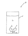
図1は、本発明の考えられる一つの上位概念を示す概略図である。(成長培地などの)液体処理を対象とするシステム10は、液体Lを収容する(細胞培養バイオリアクター、微生物発酵槽などであればよい)使い捨て式容器Vを有する。この容器Vは、液体を撹拌する撹拌機Gおよび液体を濾過するフィルターFを有する。例えば撹拌機Gに接続されることによって、フィルターFは容器V内で制御された方法で移動可能である。従って、一方が(例えば上下方向/水平方向矢印Wに対応する)任意の方向に移動すると、必然的に他方も移動し、液体を撹拌する撹拌機Gが動作する結果、フィルターFが液体を濾過する機能を発揮する。 FIG. 1 is a schematic diagram showing one possible high-level concept of the present invention. The system 10 for liquid processing (such as a growth medium) has a disposable container V that contains the liquid L (may be a cell culture bioreactor, a microbial fermenter, etc.). This container V has a stirrer G for stirring the liquid and a filter F for filtering the liquid. For example, by being connected to a stirrer G, the filter F can be moved in a controlled manner in the container V. Therefore, if one moves in any direction (for example, corresponding to the up / down / horizontal arrow W), the other inevitably also moves and the stirrer G that stirs the liquid operates, resulting in the filter F filtering the liquid. Demonstrate the function to do.
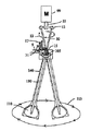
図2は、液体、特に細胞が懸濁している液体を処理する一つの考えられるシステム100を詳細に示す図である。本システム100は使い捨て式容器101を有する。この容器としては剛性をもつプラスチックタンクであればよいが、一回使用の使い捨て式バッグが好ましく、この場合剛性をもつ外側支持容れ物にバッグを設けるのが最適である(図8参照)。なお、容器101としては半剛性(semi-rigid)を示すバッグでもよい。即ち、側壁などの可撓性壁(flexible wall)、および底壁または床壁などの剛性をもつ壁を有するバッグも使用可能である。図示の容器101は全体として円筒形を取っているが、平行四辺形などの各種形態を取ることが可能であり、形態に制限はない。
FIG. 2 shows in detail one
図示の実施態様の場合、容器101は上壁(top wall)104を有し、この壁には入り口160およびアクセス口180、185を形成する。容器101の底壁(bottom wall)103は出口、即ち排液口(outlet or drain)170を有する。なお、この排液口は例えば液体の膨張または酸素化(inflation or oxygenation)を目的として、(空気や酸素などの)ガスを容器101に供給するためにも使用することができる。さらに、容器101には、例えば上壁104にそって容器101に接合したシール化スリーブ140を設けることができる。
In the illustrated embodiment, the
上記システム100は、さらに、容器101内に液体が収容されている場合この液体を撹拌する撹拌機を有する。一つの実施態様では、撹拌機としては、容器101の区画室内にミキサー120を設け、例えばその混合パドル110をシール化スリーブ140内に挿入すればよい。この混合パドル110は中空式のシャフトであればよいシャフト130に接合する。中間伝達シャフト30がガイド15を介して延在し、一端において中空シャフト130に(挿入などによって)係合する。他端にシャフトを動作するモータ99を設置する。なお、このモータは回転出力シャフト11を備えている。
The
図示の具体的な構成を詳しく説明すると、補強連結ガイド105がシャフト30を回転動作させる開口を形成する。シャフト30は、半径方向にオフセットした継ぎ手12に連結し、この継ぎ手12は上部リンク12Aおよび下部リンク12Bを有し、これらが、図示のように容器101より高い位置にあるモータ99の出力シャフト11に係合する。リンク12A−12Bにはベアリングまたはその他の回転可能な支持手段を設け、容器101の中心垂直軸線に対して角度ノンゼロ(non-zero)でほぼ円形の駆動経路で駆動されているにもかかわらず、シャフト30、130が自己の軸線を中心にして回転しないように構成することができる(つまり、シャフト30、130は回転しない)。このため、モータ99の運動エネルギーが、シャフト30、130が連続的に回転しなくても、パドル110に伝わる。このようなシャフト30、130の軸方向回転のない動作のため、容器101に(溶接などによって)シールされたスリーブ140が捩れ、あるいは裂けることがなく、あるいはパドル110を拘束することはない。
Explaining in detail the specific configuration shown in the figure, the reinforcing
モータ99は支持体8によって支持することができ、延長部9がピボットガイド15を支持する。望む場合には、このようなピボットガイド15は、2つのオフセットリンク12A、12Bがあるため省略してもよい。支持体8がさらに容器101に係合し、モータ99、伝達シャフト30およびスリーブ140間の全体の対応関係を確保することが好ましい。
The
図3は、容器101内の360°動作範囲の各位置におけるシール化スリーブ140および混合パドル110を示す図である。混合パドル110は、容器101の底面103または基底面に対して平行な面内で大きな閉じた曲線(例えばほぼ円形の)軌跡113を描いて移動する。同時に、伝達シャフト30の上端が、同じような平行面内ではあるが、ピボットガイド15より高い位置で小さな閉じた曲線(例えばほぼ円形)軌跡13を描いて移動する。パドル110のこのような移動は、シャフト30の長手軸線を中心とする連続回転を伴わないで生じる。オフセット継ぎ手12の場合ロッド30を回転させないベアリングを備えるのが好ましいが、シャフト30からピボットガイド15の上方に突出する反回転ロッド31が平行なガイドバー17間に保持されるため、シャフト30がその長手方向軸線の周りで回転することは絶対にない。パドル110の移動直径はオフセット継ぎ手12の幅、伝達シャフト30および中空シャフト130の長さ、およびシャフト30、130に対するピボットガイド15の位置を調節することによって修正することができる。
FIG. 3 is a view showing the sealing
図2に戻ると、本発明の一つの態様では、フィルター200をシステム100に対応して設けることができる。このフィルター200は容器101内に設けることができ、例えばモータ99または類似の起動装置の動作などによって、撹拌機(例えばミキサー120)と一体的に移動できるように構成することができる。例えば、図2に示すように、フィルター200はスリーブ140に直接接続する支持体202を有することができる。この支持体202は、容器101内の液体がフィルター200で濾過されるようにメッシュの細かい基材などのフィルター媒体204を保持する。このためには、導管206をフィルター200に接続すればよく、フィルター200には、媒体204がいったん通過すると、液体を一時的に保持する区画室を形成する裏張り(図示省略)を設けることができる。導管206は、例えばスリーブ130内をこれにそって通過することによって、あるいは代わりにポート180、185、場合によっては排液口170に直接接続することによって容器101の外部にある点まで延長する。いずれの場合にも、(好ましくは容器101の外部において)導管206に対応してポンプを設け、流体を(以下に説明するように、いずれか方向に)この導管に流すことができる。
Returning to FIG. 2, in one aspect of the present invention, a
いずれの場合も、図示の実施態様ではシャフト30、130のピボット作用などによって撹拌機を移動させると、フィルター200が容器101の内部で制御された方法で移動する。この移動は所定の経路に沿って生じる移動であり、フィルター200全体がそのまま上記経路にそって移動し、その軸線の周りで回転することはない。換言すれば、フィルター200は撹拌機(例えばスリーブ140を有するミキサー)に対して静止状態になっているが、両者は容器101に対して接続された状態で、あるいは縦に並んだ状態で一体に移動する。なお、シャフト30の位置を制御するなどによって撹拌機を選択的に移動させると、フィルター200の容器101内の相対的な位置を選択的に制御することができる。例えば、容器内の特定のゾーンまたは位置において任意の時点で濾過を行うことができる。
In any case, in the illustrated embodiment, when the agitator is moved by the pivoting action of the
また、容易に理解できるように、この構成はフィルター200で濾過した液体を(静的なフィルターの場合のように)容器101内の単独の静的な位置以外から確実に取り出すことができるだけでなく、フィルター媒体204の詰まりを未然に防止することができる。換言すれば、撹拌機の移動時フィルター200には液体が連続的に通過するため、フィルター媒体204の孔または開口が詰まることがなく、従って殺菌状態を破ってフィルター200を調節、あるいはクリーン化する必要もない。フィルター200が移動経路にそって比較的穏やかに移動するため、比較的高速な回転は必要なく、回転フィルターの効率を最大化でき、液体中だけでなく、システム100の動作部においても応力が付随して生じることはない。全体として、システム100の濾過装置を改良することができ、連続灌流を容易かつ比較的コストの低い方法で実施できる(従って使い捨て式装置に特に好適になる)。
Also, as can be easily understood, this configuration not only allows the liquid filtered by the
理解できるように、フィルター200は撹拌機と一体で移動する状態において異なる方法で設けることができる。例えばパドル110をスリーブと組み合わせてもよい。例えば図4に示すように、フィルター200は導管206の端部に直接設けてもよく、あるいはその内部に設けてもよい。例えば、フィルター200はメッシュのインサート208として、あるいは場合によってはキャップ(図示省略)として設ければよい。液体にガスを導入するためにスパージャー210などの装置を設けてもよく、この装置は静的な装置でもよく、あるいは図4に示すように、撹拌機に連結にしてもよい(例えばスリーブ140に接続してもよい)。
As can be appreciated, the
同様に、図5および図6に示すように、フィルター200はスリーブ140の一体的部分としてもよい。図示の実施例では、フィルター媒体204は、例えばパドル110を有する部分にそってスリーブ140の外面に直接接続している(なお、フィルター媒体204は任意の個所に設けることができる)。このためには、接着剤または溶接などによって支持体202をスリーブ140に直接接続する。導管206は、一端にスリーブ140の材質と界面を形成する周囲フランジ216を有し、そして他端にバーブ(とげ状突起)218を有する取り付け体214が形成する開口212を介して液体を受け取ることができる。この構成は液密(fluid−tight)であるため、望む場合には、殺菌状態を維持できる。
Similarly, as shown in FIGS. 5 and 6, the
上述したように、ポンプを使用して容器101からフィルター200を介して液体を取り出すことができるが、流れを定期的にかつ一時的に逆流させてフィルター媒体204をクリーン化することも可能である。なお、逆流が、フィルター200の露出面に蓄積した残渣物がある場合これの位置を変え、排出することができるため、最適な濾過の確保に役立つ。
As described above, the liquid can be removed from the
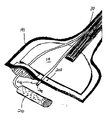
濾過装置を備えたシステムの別な実施態様を図7に示す。撹拌機は、既に概略を示したように、パドル(図示省略)を有するミキサーとスリーブ140とを組み合わせたものからなる。フィルター200はスリーブ140の中間部分にそって延在し、本質的に端部が開放したバスケットを形成し、このバスケットの閉じた下部境界は、例えば細かい(例えば<100μ)メッシュ材などのフィルター媒体204によって構成される。従って、フィルター媒体204は、細胞などの過大は粒子を含まない液体媒体が流入する内側ゾーンAと液体媒体および細胞を含む外側ゾーンBの2つのゾーンを形成する。図から理解できるように、媒体が、フィルター媒体(filter medium)204を通過できない細胞やその他の粒子を含まないゾーンAから抽出され、そして新たな液体媒体がゾーンBに導入できるように灌流構成を構成することができる。従って、撹拌機によって生じる循環によって液体がゾーン間を連続的に移動し、均一性が強くなる。
Another embodiment of a system with a filtration device is shown in FIG. As already outlined, the stirrer is composed of a combination of a mixer having a paddle (not shown) and a
図8および図9に、所定の軸線を中心にして回転する撹拌機を備えた別な実施態様を示す。図8では、フィルター200は一つかそれ以上の羽根Eをもつ回転可能なシャフトSに接続している。フィルター200はシャフトSの端部に設けることができ、容器101から液体を取り出す導管206としても作用する。なお、図示の容器101は、シャフトS/導管206の組み合わせ体を受け取るベアリングBに係合するヘッドプレートをもつ、剛性のあるタンクである。換言すると、シャフトSは液体をフィルター200に、あるいはフィルター200から伝達する導管206として作用する経路を有する。
8 and 9 show another embodiment provided with a stirrer that rotates about a predetermined axis. In FIG. 8, the
図9には、羽根Eをもち、外部モータ99によって回転するシャフトSを示す。このシャフトSはハブHによって回転可能に支持されるだけでなく、フィルター200を支持するものである。このフィルター200は(同様にメッシュなどの)フィルター媒体204および対応する支持体202を有する。導管206は液体を伝達する開口Pとフィルター200の内部区画室との間に延在し、フィルター200には接続しない。培地液体は入り口160から供給することができ、排液口170を対応して設けることができる。容器101には使い捨て式容器を使用することができ、例えば剛性のある容れ物C内に支持した可撓性バッグを使用することができる。
FIG. 9 shows a shaft S having blades E and rotated by an
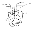
図10は、ミキサー120を備えたさらに別な実施態様を示す図である。このミキサー120は、フィルター200をもつ可撓性スリーブ140で構成することができる。回転可能なシャフト130の代わりに、スリーブ140内に磁石300を設けることができ、この場合(磁石を移動させるモータからなる装置などの)外部起動装置302を使用して、磁気結合を形成し、(流動床または固定床Dに対応する)細胞に隣接する連続経路にそって容器101内においてフィルター200を移動させる。導管206はフィルター200からヘッドプレートまで延在する。図示のように、フィルター200は、ミキサーに対応する羽根を形成する位置に設けることができ、図示のように、2つのフィルターには一つのミキサーを設けることができる。
FIG. 10 is a view showing still another embodiment including the
いくつかの本発明の原理を開示するいくつかの実施態様に関する以上の説明は、例示の説明を目的とするもので、以上の実施態様は徹底的な(exhaustive)ものではなく、また本発明を開示してきた正確な形態に制限するものではなく、即ち開示してきた実施態様の各構成成分の任意の組み合わせも包含するものである。また、容器という文脈において使用してきた“可撓性”は、容器の構造を示すものである。即ち、補助的な支持体がない場合、液体が容器に入っている場合に所定の形状を保持する“剛性のある(rigid)”部分とは対照的に、容器に収容されている液体の形状に即応することができることを意味する。以上の教示から各種の修正/変更が可能である。例えば、回転はしないが、単独で垂直方向に移動する撹拌機を、図示の撹拌機に代えて使用することは可能である。殺菌条件が望ましい場合にはいずれも、(フィルターを備える場合もある)適当なコネクタを容器101の内部の外部にある(external to the interior)導管206に設けることができる。フィルター媒体としてメッシュに言及したが、膜、多孔性の薄膜(例えばTYVEKなど)等の他のフィルター媒体も使用可能である。また、フィルター媒体は使い捨て式媒体でよいため、紙やプラスチックなどのコストの低い材質から構成することができる。あるいは、金属も使用可能であり、再使用する場合には殺菌処理すればよい。以上の実施態様は、本発明の原理およびその実際上の用途のベストな例示を与えるために選択したもので、これによって当業者ならば本発明を各種の実施態様で、しかも具体的な対象用途に応じて修正を加えた状態で本発明を利用できるはずである。このような修正/変更はいずれも、本発明の公正で法律に適う公平な範囲に従って本発明を解釈する限りにおいて本発明の範囲内にある。
The above description of several embodiments disclosing some of the principles of the present invention is for illustrative purposes only, and the above embodiments are not exhaustive and do not It is not intended to be limited to the precise form disclosed, but also to include any combination of components of the disclosed embodiments. Also, “flexibility” that has been used in the context of a container indicates the structure of the container. That is, in the absence of an auxiliary support, the shape of the liquid contained in the container as opposed to a “rigid” part that retains the predetermined shape when the liquid is in the container. It means that you can respond immediately. Various corrections / changes are possible from the above teachings. For example, a stirrer that does not rotate but moves independently in the vertical direction can be used instead of the illustrated stirrer. In any case where sterilization conditions are desired, a suitable connector (which may include a filter) may be provided in the
10、100:システム
L:液体
V、101:使い捨て式容器
G:攪拌機
F、200:フィルター
B:ベアリング
C:容れ物
S、30、130:シャフト
E:羽根
H:ハブ
110:パドル
120:ミキサー
140:スリーブ
204:フィルター媒体
10, 100: System L: Liquid V, 101: Disposable container G: Stirrer F, 200: Filter B: Bearing C: Containment S, 30, 130: Shaft E: Blade H: Hub 110: Paddle 120: Mixer 140 : Sleeve 204: Filter medium
Claims (53)
前記液体を収容する少なくとも部分的に可撓性を示す容器、および
前記液体内で制御された方法で移動するフィルターからなることを特徴とするバイオプロセシング装置。
A bioprocessing device using a liquid,
A bioprocessing device comprising: a container that accommodates the liquid and at least partially flexible; and a filter that moves in a controlled manner in the liquid.
The apparatus of claim 1, wherein the container comprises a plastic bag.
The apparatus according to claim 1, further comprising a stirrer for stirring the liquid.
The apparatus according to claim 3, wherein the filter is directly mounted on an outer surface of the agitator.
The apparatus according to claim 3 or 4, wherein the stirrer does not rotate.
5. An apparatus according to claim 3 or 4, wherein the agitator extends at least partially within a sleeve connected to the vessel.
7. The apparatus of claim 6, further comprising a conduit for transporting liquid to the filter or transporting liquid from the filter, the conduit extending at least partially within the sleeve.
The apparatus according to claim 3 or 4, wherein the agitator comprises a paddle.
9. An apparatus according to any one of claims 3 to 8, wherein the paddle is mounted for pivotal movement.
The apparatus according to claim 3, wherein the agitator rotates about a predetermined axis.
The apparatus of claim 10, further comprising a rotatable hub corresponding to the vessel and the agitator.
Furthermore, the apparatus of Claim 10 or 11 which has a bearing corresponding to the said container and the said stirrer.
The apparatus according to any one of claims 3 to 12, wherein the filter substantially surrounds the agitator.
14. A device according to any one of the preceding claims, wherein the filter is integral with the sleeve.
The device according to claim 1, wherein the filter is made of a mesh that allows liquid to pass but does not allow cells to pass.
The apparatus according to claim 1, wherein the filter is made of a membrane that allows liquid to pass but does not allow cells to pass.
17. The filter according to claim 1, wherein the filter is configured to divide the liquid in the internal compartment of the container into a first zone substantially free of cells and a second zone containing cells. The device described.
The apparatus of claim 17, further comprising a first conduit for removing liquid from the first zone and a second conduit for feeding liquid to the second zone.
The apparatus according to claim 1, further comprising a pump corresponding to the filter.
The apparatus of claim 19, wherein the pump pumps liquid from the container to the filter.
The apparatus of claim 19, wherein the pump pumps liquid from the container to the filter.
The apparatus according to claim 1, further comprising a sparger that introduces gas into the liquid.
Furthermore, the apparatus of any one of Claims 1-22 which has a filter outside the internal compartment of the said container.
前記液体の、可撓性壁を有する容器、
前記液体を撹拌する撹拌機、および
前記液体を濾過する、前記撹拌機に取り付けられたフィルターからなることを特徴とする装置。
An apparatus for processing liquids,
A container of said liquid having a flexible wall;
An apparatus comprising: a stirrer for stirring the liquid; and a filter attached to the stirrer for filtering the liquid.
前記液体を収容する容器、
前記液体を撹拌する撹拌機、
前記容器内の前記撹拌機に接続して、前記液体内で前記撹拌機を移動させる起動装置、および
前記液体を濾過する、前記撹拌機に取り付けられたフィルターからなることを特徴とする装置。
An apparatus for processing liquids,
A container containing the liquid,
A stirrer for stirring the liquid;
An apparatus comprising: an activation device connected to the stirrer in the container to move the stirrer in the liquid; and a filter attached to the stirrer for filtering the liquid.
26. Apparatus according to claim 24 or 25, wherein the container comprises a bag.
27. The apparatus according to any one of claims 24 to 26, wherein the agitator corresponds to a sleeve provided in a compartment of the container.
28. Apparatus according to any one of claims 24 to 27, further comprising a conduit corresponding to the filter, the conduit located at least partially within the sleeve.
29. Apparatus according to any one of claims 24 to 28, wherein the agitator has a paddle.
30. The apparatus of claim 29, wherein the paddle is mounted for pivotal movement relative to the container.
The device according to any one of claims 24 to 30, wherein the filter is made of a mesh that allows liquid to pass but does not allow cells to pass.
The device according to any one of claims 24 to 30, wherein the filter is made of a membrane that allows liquid to pass but does not allow cells to pass.
33. The apparatus of claim 32, wherein the filter separates the first portion of the liquid that is substantially free of cells from the second portion of the liquid that contains cells.
34. The apparatus of claim 33, further comprising a conduit for removing liquid from the first portion and a second conduit for adding liquid to the second portion.
35. Apparatus according to any one of claims 24 to 34, further comprising a pump corresponding to the filter.
36. The apparatus of claim 35, wherein the pump pumps liquid from the container to the filter.
36. The apparatus of claim 35, wherein the pump pumps liquid through the filter into the container.
The apparatus according to any one of claims 24 to 37, further comprising a sparger that introduces gas into the liquid of the container.
少なくとも一つの可撓性壁を有する、前記液体を収容する容器、
前記液体を濾過する移動可能なフィルター、および
前記フィルターを前記液体内で移動させる起動装置からなることを特徴とする前記装置。
An apparatus used for liquid processing,
A container containing the liquid, having at least one flexible wall;
The apparatus comprising: a movable filter for filtering the liquid; and an activation device for moving the filter in the liquid.
40. The apparatus of claim 39, wherein the container comprises a flexible bag and further has a rigid container that supports the bag.
40. The apparatus of claim 39, further comprising a support structure that supports the motor at a higher position than the bag.
前記液体を濾過するフィルター、および
前記液体中を非線形経路にそって前記フィルターを移動させる起動装置からなることを特徴とする濾過装置。
A filtration device for use in a container intended for liquid,
A filtration device comprising: a filter that filters the liquid; and an activation device that moves the filter along a non-linear path in the liquid.
43. The apparatus of claim 42, further comprising a support for supporting the filter at a position higher than the container floor.
43. The apparatus of claim 42, wherein the activation device comprises a magnet and further includes an agitator that forms a magnetic coupling with the magnet of the activation device.
An apparatus for use in liquid processing, wherein at least a part of the apparatus having at least one blade comprises a magnetic mixer, and the mixer further includes a filter for filtering the liquid.
An apparatus used for liquid treatment, comprising a mixer having blades for stirring the liquid, wherein the blades have a filter for the liquid.
An apparatus for use in liquid processing, comprising: a shaft having at least one blade for stirring the liquid, wherein the shaft has a filter for filtering the liquid.
48. The apparatus of claim 47, wherein the shaft comprises a flexible sleeve.
48. The apparatus of claim 47, wherein the annular shaft is rigid.
50. A bioreactor comprising the apparatus of any one of claims 1-49.
前記液体を収容する容器内の前記液体を濾過するフィルターを用意するステップ、そして
前記容器内のシャフトを、このシャフトが前記液体に接触することなく、前記フィルターに接続するステップからなることを特徴とする前記方法。
A method of handling liquids,
Providing a filter for filtering the liquid in a container containing the liquid, and connecting a shaft in the container to the filter without the shaft contacting the liquid. Said method.
52. The method of claim 51, wherein connecting the shaft inserts the shaft into a sleeve within the container.
Applications Claiming Priority (3)
| Application Number | Priority Date | Filing Date | Title |
|---|---|---|---|
| US201161568872P | 2011-12-09 | 2011-12-09 | |
| US61/568,872 | 2011-12-09 | ||
| PCT/US2012/068513 WO2013086371A1 (en) | 2011-12-09 | 2012-12-07 | Filtration apparatus for continuous perfusion |
Publications (2)
| Publication Number | Publication Date |
|---|---|
| JP2015500033A true JP2015500033A (en) | 2015-01-05 |
| JP2015500033A5 JP2015500033A5 (en) | 2016-01-14 |
Family
ID=48574930
Family Applications (1)
| Application Number | Title | Priority Date | Filing Date |
|---|---|---|---|
| JP2014546134A Pending JP2015500033A (en) | 2011-12-09 | 2012-12-07 | Continuous perfusion filtration equipment |
Country Status (7)
| Country | Link |
|---|---|
| US (1) | US20140370588A1 (en) |
| EP (1) | EP2788468A4 (en) |
| JP (1) | JP2015500033A (en) |
| CN (1) | CN104619827A (en) |
| CA (1) | CA2861519A1 (en) |
| SG (1) | SG11201402997QA (en) |
| WO (1) | WO2013086371A1 (en) |
Cited By (1)
| Publication number | Priority date | Publication date | Assignee | Title |
|---|---|---|---|---|
| JP2019505240A (en) * | 2016-02-23 | 2019-02-28 | コーニング インコーポレイテッド | Perfusion bioreactor and method of use for performing continuous cell culture |
Families Citing this family (8)
| Publication number | Priority date | Publication date | Assignee | Title |
|---|---|---|---|---|
| US9248420B2 (en) * | 2013-12-16 | 2016-02-02 | Pall Corporation | High turndown impeller |
| EP2944372A1 (en) * | 2014-05-17 | 2015-11-18 | Miltenyi Biotec GmbH | Method and device for suspending cells |
| EP3215261B1 (en) | 2014-11-07 | 2021-12-15 | Genesis Technologies, LLC | Linear reciprocating actuator |
| WO2016107788A1 (en) * | 2014-12-31 | 2016-07-07 | Ge Healthcare Bio-Sciences Corp. | Shaft-mounted fluid transfer assembly for a disposable bioreactor |
| ITUB20154901A1 (en) * | 2015-10-22 | 2017-04-22 | Paolo Gobbi Frattini S R L | NEW BAG FOR THE PREPARATION OF ADIPOSE FABRIC CLOTHES |
| EP3397377B1 (en) | 2015-12-29 | 2022-03-02 | Life Technologies Corporation | Fluid mixing system with laterally displaced flexible drive lines and methods of use |
| CN113522132B (en) * | 2021-07-19 | 2023-05-26 | 山东农业工程学院 | Water, fertilizer and pesticide uniform mixing device for agricultural drip irrigation |
| FR3141686A1 (en) * | 2022-11-03 | 2024-05-10 | Gary Kane Concept | Cap for fluid sample dispenser. |
Citations (6)
| Publication number | Priority date | Publication date | Assignee | Title |
|---|---|---|---|---|
| US4184916A (en) * | 1977-11-14 | 1980-01-22 | Monsanto Company | Continuous cell culture system |
| JPH04252175A (en) * | 1991-01-28 | 1992-09-08 | Teijin Ltd | Tank of cell culture |
| US20090027997A1 (en) * | 2005-10-03 | 2009-01-29 | Zeta Ag Bioprocess Systems | Single-Use Container With Stirring Device |
| JP2009513140A (en) * | 2005-10-26 | 2009-04-02 | リーブテック,インコーポレイテッド | Bioreactor with mixer and sparger |
| US20100015696A1 (en) * | 2006-05-13 | 2010-01-21 | Tom Claes | Disposable bioreactor |
| WO2011005773A2 (en) * | 2009-07-06 | 2011-01-13 | Genentech, Inc. | Method of culturing eukaryotic cells |
Family Cites Families (8)
| Publication number | Priority date | Publication date | Assignee | Title |
|---|---|---|---|---|
| US4596779A (en) * | 1983-03-23 | 1986-06-24 | Bellco Glass, Inc. | Culture vessel with agitator |
| US4649118A (en) * | 1984-04-05 | 1987-03-10 | The Virtis Company, Inc. | Cell culturing apparatus with improved stirring and filter means |
| US20050032211A1 (en) * | 1996-09-26 | 2005-02-10 | Metabogal Ltd. | Cell/tissue culturing device, system and method |
| US6670171B2 (en) * | 2001-07-09 | 2003-12-30 | Wheaton Usa, Inc. | Disposable vessel |
| US7249880B2 (en) * | 2003-10-14 | 2007-07-31 | Advanced Technology Materials, Inc. | Flexible mixing bag for mixing solids, liquids and gases |
| US7875448B2 (en) * | 2004-01-12 | 2011-01-25 | Single Use Brx, Llc | Bioreactor systems and disposable bioreactor |
| US9109193B2 (en) * | 2007-07-30 | 2015-08-18 | Ge Healthcare Bio-Sciences Corp. | Continuous perfusion bioreactor system |
| US7832922B2 (en) * | 2007-11-30 | 2010-11-16 | Levitronix Gmbh | Mixing apparatus and container for such |
-
2012
- 2012-12-07 CN CN201280068431.0A patent/CN104619827A/en active Pending
- 2012-12-07 EP EP12856385.5A patent/EP2788468A4/en not_active Withdrawn
- 2012-12-07 WO PCT/US2012/068513 patent/WO2013086371A1/en active Application Filing
- 2012-12-07 SG SG11201402997QA patent/SG11201402997QA/en unknown
- 2012-12-07 CA CA2861519A patent/CA2861519A1/en not_active Abandoned
- 2012-12-07 JP JP2014546134A patent/JP2015500033A/en active Pending
- 2012-12-07 US US14/363,825 patent/US20140370588A1/en not_active Abandoned
Patent Citations (6)
| Publication number | Priority date | Publication date | Assignee | Title |
|---|---|---|---|---|
| US4184916A (en) * | 1977-11-14 | 1980-01-22 | Monsanto Company | Continuous cell culture system |
| JPH04252175A (en) * | 1991-01-28 | 1992-09-08 | Teijin Ltd | Tank of cell culture |
| US20090027997A1 (en) * | 2005-10-03 | 2009-01-29 | Zeta Ag Bioprocess Systems | Single-Use Container With Stirring Device |
| JP2009513140A (en) * | 2005-10-26 | 2009-04-02 | リーブテック,インコーポレイテッド | Bioreactor with mixer and sparger |
| US20100015696A1 (en) * | 2006-05-13 | 2010-01-21 | Tom Claes | Disposable bioreactor |
| WO2011005773A2 (en) * | 2009-07-06 | 2011-01-13 | Genentech, Inc. | Method of culturing eukaryotic cells |
Cited By (2)
| Publication number | Priority date | Publication date | Assignee | Title |
|---|---|---|---|---|
| JP2019505240A (en) * | 2016-02-23 | 2019-02-28 | コーニング インコーポレイテッド | Perfusion bioreactor and method of use for performing continuous cell culture |
| US11136542B2 (en) | 2016-02-23 | 2021-10-05 | Corning Incorporated | Perfusion bioreactor and method for using same to perform a continuous cell culture |
Also Published As
| Publication number | Publication date |
|---|---|
| CN104619827A (en) | 2015-05-13 |
| SG11201402997QA (en) | 2014-07-30 |
| US20140370588A1 (en) | 2014-12-18 |
| EP2788468A1 (en) | 2014-10-15 |
| WO2013086371A1 (en) | 2013-06-13 |
| EP2788468A4 (en) | 2015-09-16 |
| CA2861519A1 (en) | 2013-06-13 |
Similar Documents
| Publication | Publication Date | Title |
|---|---|---|
| JP2015500033A (en) | Continuous perfusion filtration equipment | |
| CN101466466B (en) | Reactor | |
| JP6840219B2 (en) | Bioreactor system and its method | |
| US6670171B2 (en) | Disposable vessel | |
| JP6605251B2 (en) | Single-use cell culture device and culture bag | |
| CA2627654C (en) | Bioreactor with mixer and sparger | |
| JP2007534335A (en) | Stirred tank reactor system | |
| JP6739273B2 (en) | Single-use culture apparatus and culture method | |
| SG176507A1 (en) | Disposable bioreactor | |
| AU2002346088A1 (en) | Disposable vessel | |
| WO2008040567A1 (en) | Flexible mixing bag, mixing device and mixing system | |
| JP2002512109A (en) | Rotary filtration device with flow-through inner member | |
| JP2021517817A (en) | Single-use container containing a foldable baffle with channels | |
| JP4561192B2 (en) | Cell culture device and cell culture method | |
| CN107438478B (en) | Biological treatment mixer | |
| JP2018161115A (en) | Cell culture apparatus and cell culture method | |
| JP6744161B2 (en) | Separation device, culture device and separation method | |
| WO2010063845A1 (en) | Liquid substance circulation device comprising a compartment for an impeller having a sloped upper portion | |
| WO2019077623A1 (en) | An improved disposable bioreactor | |
| US20190169561A1 (en) | In-situ cell retention perfusion bioreactors | |
| CN102272285A (en) | Method for reducing deposits during the cultivation of organisms | |
| JP2002045173A (en) | Method for culturing cell cluster and bioreactor | |
| JPH05304943A (en) | Device for culturing organism | |
| CN113727775A (en) | Impeller assembly for a bioprocessing system | |
| US20240018453A1 (en) | Bioprocessing vessel having integral fluid conduit |
Legal Events
| Date | Code | Title | Description |
|---|---|---|---|
| A521 | Request for written amendment filed |
Free format text: JAPANESE INTERMEDIATE CODE: A523 Effective date: 20151119 |
|
| A621 | Written request for application examination |
Free format text: JAPANESE INTERMEDIATE CODE: A621 Effective date: 20151119 |
|
| A977 | Report on retrieval |
Free format text: JAPANESE INTERMEDIATE CODE: A971007 Effective date: 20160715 |
|
| A131 | Notification of reasons for refusal |
Free format text: JAPANESE INTERMEDIATE CODE: A131 Effective date: 20160802 |
|
| A02 | Decision of refusal |
Free format text: JAPANESE INTERMEDIATE CODE: A02 Effective date: 20170228 |