JP2015227724A - Method and apparatus for reducing structural vibration and noise - Google Patents
Method and apparatus for reducing structural vibration and noise Download PDFInfo
- Publication number
- JP2015227724A JP2015227724A JP2015079851A JP2015079851A JP2015227724A JP 2015227724 A JP2015227724 A JP 2015227724A JP 2015079851 A JP2015079851 A JP 2015079851A JP 2015079851 A JP2015079851 A JP 2015079851A JP 2015227724 A JP2015227724 A JP 2015227724A
- Authority
- JP
- Japan
- Prior art keywords
- edge
- sheet
- structural panel
- damping layer
- constraining
- Prior art date
- Legal status (The legal status is an assumption and is not a legal conclusion. Google has not performed a legal analysis and makes no representation as to the accuracy of the status listed.)
- Granted
Links
- 238000000034 method Methods 0.000 title claims abstract description 31
- 238000013016 damping Methods 0.000 claims abstract description 83
- 239000003190 viscoelastic substance Substances 0.000 claims abstract description 21
- 230000005540 biological transmission Effects 0.000 claims abstract description 8
- 239000002131 composite material Substances 0.000 claims description 56
- 230000008878 coupling Effects 0.000 claims description 19
- 238000010168 coupling process Methods 0.000 claims description 19
- 238000005859 coupling reaction Methods 0.000 claims description 19
- 239000006260 foam Substances 0.000 claims description 15
- 230000000452 restraining effect Effects 0.000 claims description 15
- 230000007423 decrease Effects 0.000 claims description 7
- 229920000877 Melamine resin Polymers 0.000 claims description 6
- 239000004721 Polyphenylene oxide Substances 0.000 claims description 6
- 229920005830 Polyurethane Foam Polymers 0.000 claims description 6
- JDSHMPZPIAZGSV-UHFFFAOYSA-N melamine Chemical compound NC1=NC(N)=NC(N)=N1 JDSHMPZPIAZGSV-UHFFFAOYSA-N 0.000 claims description 6
- 229920000570 polyether Polymers 0.000 claims description 6
- 239000011496 polyurethane foam Substances 0.000 claims description 6
- 239000000853 adhesive Substances 0.000 claims description 5
- 230000001070 adhesive effect Effects 0.000 claims description 5
- 239000013013 elastic material Substances 0.000 claims description 5
- XAGFODPZIPBFFR-UHFFFAOYSA-N aluminium Chemical compound [Al] XAGFODPZIPBFFR-UHFFFAOYSA-N 0.000 claims description 4
- 229910052782 aluminium Inorganic materials 0.000 claims description 4
- 230000001737 promoting effect Effects 0.000 claims description 2
- 230000003247 decreasing effect Effects 0.000 abstract 1
- 230000005534 acoustic noise Effects 0.000 description 15
- 239000000463 material Substances 0.000 description 11
- 230000009467 reduction Effects 0.000 description 6
- 230000006870 function Effects 0.000 description 5
- 238000010586 diagram Methods 0.000 description 3
- 238000010521 absorption reaction Methods 0.000 description 2
- 230000002238 attenuated effect Effects 0.000 description 2
- 239000006261 foam material Substances 0.000 description 2
- 230000006698 induction Effects 0.000 description 2
- 230000004044 response Effects 0.000 description 2
- 150000001875 compounds Chemical class 0.000 description 1
- 125000004122 cyclic group Chemical group 0.000 description 1
- 238000005553 drilling Methods 0.000 description 1
- 229920001971 elastomer Polymers 0.000 description 1
- 239000003365 glass fiber Substances 0.000 description 1
- 229920002635 polyurethane Polymers 0.000 description 1
- 239000004814 polyurethane Substances 0.000 description 1
Images
Classifications
-
- B—PERFORMING OPERATIONS; TRANSPORTING
- B64—AIRCRAFT; AVIATION; COSMONAUTICS
- B64C—AEROPLANES; HELICOPTERS
- B64C1/00—Fuselages; Constructional features common to fuselages, wings, stabilising surfaces or the like
- B64C1/40—Sound or heat insulation, e.g. using insulation blankets
-
- F—MECHANICAL ENGINEERING; LIGHTING; HEATING; WEAPONS; BLASTING
- F16—ENGINEERING ELEMENTS AND UNITS; GENERAL MEASURES FOR PRODUCING AND MAINTAINING EFFECTIVE FUNCTIONING OF MACHINES OR INSTALLATIONS; THERMAL INSULATION IN GENERAL
- F16F—SPRINGS; SHOCK-ABSORBERS; MEANS FOR DAMPING VIBRATION
- F16F9/00—Springs, vibration-dampers, shock-absorbers, or similarly-constructed movement-dampers using a fluid or the equivalent as damping medium
- F16F9/30—Springs, vibration-dampers, shock-absorbers, or similarly-constructed movement-dampers using a fluid or the equivalent as damping medium with solid or semi-solid material, e.g. pasty masses, as damping medium
- F16F9/306—Springs, vibration-dampers, shock-absorbers, or similarly-constructed movement-dampers using a fluid or the equivalent as damping medium with solid or semi-solid material, e.g. pasty masses, as damping medium of the constrained layer type, i.e. comprising one or more constrained viscoelastic layers
-
- G—PHYSICS
- G10—MUSICAL INSTRUMENTS; ACOUSTICS
- G10K—SOUND-PRODUCING DEVICES; METHODS OR DEVICES FOR PROTECTING AGAINST, OR FOR DAMPING, NOISE OR OTHER ACOUSTIC WAVES IN GENERAL; ACOUSTICS NOT OTHERWISE PROVIDED FOR
- G10K11/00—Methods or devices for transmitting, conducting or directing sound in general; Methods or devices for protecting against, or for damping, noise or other acoustic waves in general
- G10K11/16—Methods or devices for protecting against, or for damping, noise or other acoustic waves in general
- G10K11/162—Selection of materials
- G10K11/168—Plural layers of different materials, e.g. sandwiches
-
- B—PERFORMING OPERATIONS; TRANSPORTING
- B64—AIRCRAFT; AVIATION; COSMONAUTICS
- B64C—AEROPLANES; HELICOPTERS
- B64C1/00—Fuselages; Constructional features common to fuselages, wings, stabilising surfaces or the like
- B64C2001/0054—Fuselage structures substantially made from particular materials
- B64C2001/0072—Fuselage structures substantially made from particular materials from composite materials
-
- B—PERFORMING OPERATIONS; TRANSPORTING
- B64—AIRCRAFT; AVIATION; COSMONAUTICS
- B64C—AEROPLANES; HELICOPTERS
- B64C1/00—Fuselages; Constructional features common to fuselages, wings, stabilising surfaces or the like
- B64C2001/0054—Fuselage structures substantially made from particular materials
- B64C2001/0081—Fuselage structures substantially made from particular materials from metallic materials
Landscapes
- Engineering & Computer Science (AREA)
- General Engineering & Computer Science (AREA)
- Mechanical Engineering (AREA)
- Physics & Mathematics (AREA)
- Acoustics & Sound (AREA)
- Multimedia (AREA)
- Aviation & Aerospace Engineering (AREA)
- Vibration Prevention Devices (AREA)
- Soundproofing, Sound Blocking, And Sound Damping (AREA)
- Laminated Bodies (AREA)
- Vibration Dampers (AREA)
Abstract
Description
本開示の分野は、全体的に振動および音響ノイズの低減に関し、より詳細には、航空機または車両構造体の振動、および航空機または車両構造体を通る音響伝達を減衰するための方法および装置に関する。 The field of the disclosure relates generally to vibration and acoustic noise reduction, and more particularly to methods and apparatus for attenuating vibrations in an aircraft or vehicle structure and acoustic transmission through the aircraft or vehicle structure.
多くの構造体は、様々な原因から構造由来の振動および音響ノイズの影響を受ける。一実施例として、航空機および車両構造体は、通常、作動中に振動および音響ノイズを発生するエンジンを含む。そのような構造体は、更に、通常は空気力学的力によって生成される振動および/または音響源など、他の振動および/または音響源の影響を受ける。その結果、そのような構造体の多くは、構造振動および音響ノイズが客室に到達することを防止するように意図されたシステムを含む。しかし少なくともそのようなシステムのいくつかは、構造由来の振動を減衰し、音響ノイズを吸収する別個の装置が必要である。 Many structures are affected by structural vibrations and acoustic noise from various sources. As one example, aircraft and vehicle structures typically include engines that generate vibration and acoustic noise during operation. Such structures are also subject to other vibration and / or acoustic sources, such as vibration and / or acoustic sources that are typically generated by aerodynamic forces. As a result, many such structures include systems that are intended to prevent structural vibrations and acoustic noise from reaching the cabin. However, at least some of such systems require a separate device that attenuates structural vibrations and absorbs acoustic noise.
例えば、少なくともいくつかの公知の航空機および車両構造体は、拘束層減衰装置を備え、その減衰装置では、ゴムまたはポリウレタンのシートなど、振動減衰材料の層の一方の側が構造面に結合され、反対側が拘束層に結合される。減衰層内の任意の位置での振動変形に対して、拘束層は、構造面に平行な方向に減衰層内部でせん断変形を誘発する。したがって減衰層内のせん断変形の誘発が、振動エネルギーの部分を減衰する。しかしそのような公知の拘束層減衰装置は、振動周波数および環境温度によって重大にも変化する減衰をもたらし、それらは空気由来のノイズをほとんど吸収しない。いくつかの公知の拘束層減衰装置は、粘弾性フォーム減衰層を使用して、効果的な減衰のための周波数および温度の範囲を改善するが、しかしそのような装置はやはり、せん断変形が構造面に平行な減衰層内に誘発される程度までにエネルギーを減衰するに過ぎない。 For example, at least some known aircraft and vehicle structures include a constrained layer damping device in which one side of a layer of vibration damping material, such as a rubber or polyurethane sheet, is bonded to the structural surface and opposite The side is bonded to the constraining layer. With respect to vibration deformation at an arbitrary position in the damping layer, the constraining layer induces shear deformation inside the damping layer in a direction parallel to the structural surface. Thus, the induction of shear deformation in the damping layer attenuates the portion of vibration energy. However, such known constrained layer damping devices provide damping that varies significantly with vibration frequency and ambient temperature, and they absorb very little airborne noise. Some known constrained layer damping devices use viscoelastic foam damping layers to improve the frequency and temperature range for effective damping, but such devices still have shear deformation structures. It only attenuates energy to the extent that it is induced in an attenuation layer parallel to the plane.
更に、少なくともいくつかの公知の航空機および車両構造体は、客室の構造体とパネルとの間に配置された音響ブランケットを備える。ブランケットは、空気由来のノイズを吸収するガラス繊維または軽量の連続気泡フォームなどの材料を含む。しかしそのような公知のブランケットは、構造由来の振動の減衰をほとんど提供しない。 In addition, at least some known aircraft and vehicle structures include an acoustic blanket disposed between the cabin structure and the panel. The blanket includes materials such as glass fiber or lightweight open cell foam that absorbs air-derived noise. However, such known blankets provide little damping of structural vibrations.
加えて、少なくともいくつかの公知の構造体は、「スマートフォーム」と呼ばれることが多い、埋設されたアクチュエータを備える音吸収フォームを使用する。そのような公知のスマートフォーム装置は、平坦な基部および反対側の弧状上方面を含む軽量のフォーム層を含む。平坦な基部は構造体に結合され、弧状面は薄い圧電フィルムに結合される。フォームによって提供される音響ノイズ吸収を追加する目的で、圧電フィルムが、音響ノイズを打ち消す音波を生成するためにフォームを膨張および収縮するように積極的に制御される。しかしながら、構造面に垂直なフォームの変形のすべてではないにしても、そのほとんどが圧電フィルムによって積極的に誘発されて、ノイズ打消し音波を生成する。更に、フォームが、薄い圧電フィルムの積極的に制御された振動のために弾性支持基礎を提供し、音響エネルギーを吸収することができるように選択される。したがって、フォーム内の変形の誘発が、構造由来の振動からの実質的な振動エネルギーを減衰しない。加えて、圧電フィルムおよび積極的制御システムは、例えば補助的な制御構成要素により、追加の費用、重量、および複雑さをノイズ低減装置にもたらす。 In addition, at least some known structures use sound absorbing foams with embedded actuators, often referred to as “smart foams”. Such known smart foam devices include a lightweight foam layer that includes a flat base and an opposing arcuate upper surface. The flat base is bonded to the structure and the arcuate surface is bonded to a thin piezoelectric film. In order to add the acoustic noise absorption provided by the foam, the piezoelectric film is actively controlled to expand and contract the foam to generate sound waves that cancel the acoustic noise. However, most if not all of the foam deformation perpendicular to the structural surface is actively induced by the piezoelectric film to generate noise canceling sound waves. In addition, the foam is selected to provide an elastic support foundation for the positively controlled vibration of the thin piezoelectric film and to absorb acoustic energy. Thus, induction of deformation in the foam does not attenuate substantial vibrational energy from structure-derived vibrations. In addition, the piezoelectric film and active control system introduce additional cost, weight, and complexity to the noise reduction device, for example with an auxiliary control component.
一態様では、構造パネルのための複合ダンパが提供される。複合ダンパが、第1の縁部と第2の縁部との間に延伸する拘束シートを含む。第1の縁部および第2の縁部のそれぞれが、少なくとも部分的に構造パネルの第1の面に結合されている。複合ダンパは、更に、拘束シートと第1の面との間に結合された減衰層を含み、構造パネルが圧縮して変形された状態である場合、第1の面に略垂直な方向に減衰層の厚さが、基準線状態に対して減少するようにする。減衰層が粘弾性材料を含む。 In one aspect, a composite damper for a structural panel is provided. The composite damper includes a constraining sheet that extends between the first edge and the second edge. Each of the first edge and the second edge is at least partially coupled to the first surface of the structural panel. The composite damper further includes a damping layer coupled between the constraining sheet and the first surface, and when the structural panel is compressed and deformed, attenuates in a direction substantially perpendicular to the first surface. The layer thickness is reduced relative to the baseline condition. The damping layer includes a viscoelastic material.
別の態様では、構造パネルが提供される。パネルが、第1の面と、第1の面に結合された少なくとも1つの複合ダンパとを含む。少なくとも1つの複合ダンパが、第1の縁部と第2の縁部との間に延伸する拘束シートを含む。第1の縁部および第2の縁部のそれぞれが、少なくとも部分的に第1の面に結合されている。複合ダンパは、更に、拘束シートと第1の面との間に結合された減衰層を備え、構造パネルが圧縮して変形された状態である場合、第1の面に略垂直な方向に減衰層の厚さが、基準線状態に対して減少するようにする。減衰層が粘弾性材料を含む。 In another aspect, a structural panel is provided. The panel includes a first surface and at least one composite damper coupled to the first surface. At least one composite damper includes a constraining sheet extending between the first edge and the second edge. Each of the first edge and the second edge is at least partially coupled to the first surface. The composite damper further includes a damping layer coupled between the constraining sheet and the first surface, and when the structural panel is in a state of being compressed and deformed, the composite damper is attenuated in a direction substantially perpendicular to the first surface. The layer thickness is reduced relative to the baseline condition. The damping layer includes a viscoelastic material.
別の態様では、構造パネルの中の構造振動およびノイズ伝達を低減するための方法が提供される。方法は、拘束シートの第1の縁部を少なくとも部分的に構造パネルの第1の面に結合するステップと、拘束シートの第2の縁部を少なくとも部分的に第1の面に結合するステップとを含む。方法は、更に、減衰層に粘弾性材料を提供するステップと、拘束シートと前記第1の面との間に減衰層を結合するステップであって、構造パネルが圧縮して変形された状態である場合、第1の面に略垂直な方向に減衰層の厚さが、基準線状態に対して減少するようにするステップとを含む。 In another aspect, a method is provided for reducing structural vibration and noise transmission in a structural panel. The method includes at least partially coupling the first edge of the constraining sheet to the first surface of the structural panel and coupling the second edge of the constraining sheet at least partially to the first surface. Including. The method further includes providing a viscoelastic material to the damping layer and coupling the damping layer between the constraining sheet and the first surface, wherein the structural panel is compressed and deformed. In some cases, the step of reducing the thickness of the attenuation layer relative to the baseline condition in a direction substantially perpendicular to the first surface.
更に本開示は、以下の付則による実施形態を備える。
付則1
構造パネルのための複合ダンパであって、
第1の縁部と第2の縁部との間に延伸する拘束シートであって、前記第1の縁部および前記第2の縁部のそれぞれが、少なくとも部分的に前記構造パネルの第1の面に結合されている拘束シートと、
前記拘束シートと前記第1の面との間に結合された減衰層であって、前記構造パネルが圧縮して変形された状態である場合、前記第1の面に略垂直な方向に前記減衰層の厚さが、基準線状態に対して減少するようにし、前記減衰層が粘弾性材料を含む、減衰層と
を備える複合ダンパ。
付則2
前記構造パネルが前記圧縮して変形された状態である場合、前記第1の縁部と前記第2の縁部との間の第2の距離が増加する、付則1に記載の複合ダンパ。
付則3
前記粘弾性材料が、ポリエーテル系ポリウレタンフォームを含む、付則1に記載の複合ダンパ。
付則4
前記粘弾性材料が、連続気泡メラミンフォームを含む、付則1に記載の複合ダンパ。
付則5
前記拘束シートが、弾性材料のシートを含む、付則1に記載の複合ダンパ。
付則6
前記拘束シートが、アルミニウムを含む、付則1に記載の複合ダンパ。
付則7
前記拘束シートが、前記拘束シートを貫通してそれぞれ延伸する複数の穿孔を含み、前記複数の穿孔が、前記拘束層を通過して前記減衰層に入る音波を促進するために適切な寸法および間隔を含む、付則1に記載の複合ダンパ。
付則8
航空機のための構造パネルであって、
第1の面と、
前記第1の面に結合された少なくとも1つの複合ダンパであって、
第1の縁部と第2の縁部との間に延伸する拘束シートであって、前記第の1縁部および前記第2の縁部のそれぞれが、少なくとも部分的に前記第1の面に結合されている、拘束シートと、
前記拘束シートと前記第1の面との間に結合された減衰層であって、前記構造パネルが圧縮して変形された状態である場合、前記第1の面に略垂直な方向に前記減衰層の厚さが、基準線状態に対して減少するようにし、前記減衰層が粘弾性材料を含む、減衰層と
を備える少なくとも1つの複合ダンパと
を備える構造パネル。
付則9
前記構造パネルが前記圧縮して変形された状態である場合、前記第1の縁部と前記第2の縁部との間の第2の距離が増加する、付則8に記載の構造パネル。
付則10
前記粘弾性材料が、ポリエーテル系ポリウレタンフォームを含む、付則8に記載の構造パネル。
付則11
前記粘弾性材料が、連続気泡メラミンフォームを含む、付則8に記載の構造パネル。
付則12
前記拘束シートが、弾性材料のシートを含む、付則8に記載の構造パネル。
付則13
前記拘束シートが、アルミニウムの薄いシートを含む、付則8に記載の構造パネル。
付則14
前記拘束シートが、前記拘束シートを貫通してそれぞれ延伸する複数の穿孔を含み、前記複数の穿孔が、前記拘束層を通過して前記減衰層の中に入る音波を促進するための適切な寸法および間隔を含む、付則8に記載の構造パネル。
付則15
構造パネルの中の構造振動およびノイズ伝達を低減するための方法であって、
拘束シートの第1の縁部を少なくとも部分的に前記構造パネルの第1の面に結合するステップと、
前記拘束シートの第2の縁部を少なくとも部分的に前記第1の面に結合するステップと、
減衰層に粘弾性材料を提供するステップと、
前記拘束シートと前記第1の面との間に減衰層を結合するステップであって、前記構造パネルが圧縮して変形された状態である場合、前記第1の面に略垂直な方向に前記減衰層の厚さが、基準線状態に対して減少するようにするステップと
を含む方法。
付則16
前記拘束シートの前記第1の縁部および前記第2の縁部を少なくとも部分的に前記第1の面にそれぞれ結合するステップが、更に、前記構造パネルが前記圧縮して変形された状態である場合、前記第1の縁部と前記第2の縁部との間の第2の距離が増加するように、前記第1の縁部および前記第2の縁部を少なくとも部分的に前記第1の面に結合するステップを含む、付則15に記載の方法。
付則17
前記減衰層に粘弾性材料を提供するステップが、更に、前記減衰層にポリエーテル系ポリウレタンフォーム材料を提供するステップを含む、付則15に記載の方法。
付則18
前記減衰層に粘弾性材料を提供するステップが、更に、前記減衰層に連続気泡メラミンフォーム材料を提供するステップを含む、付則15に記載の方法。
付則19
前記拘束シートの前記第1の縁部および前記第2の縁部を少なくとも部分的に前記第1の面にそれぞれ前記結合するステップが、更に、接着剤を使用して、前記第1の縁部および前記第2の縁部を少なくとも部分的に前記第1の面に結合するステップを含む、付則15に記載の方法。
付則20
前記拘束シートを貫通してそれぞれ延伸する複数の穿孔を提供するステップを更に含み、前記複数の穿孔が、前記拘束層を通過して前記減衰層の中に入る音波を促進するための適切な寸法および間隔を含む、付則15に記載の方法。
Furthermore, the present disclosure includes embodiments according to the following supplementary rules.
Appendix 1
A composite damper for a structural panel,
A constraining sheet extending between a first edge and a second edge, wherein each of the first edge and the second edge is at least partially in the first of the structural panel A restraint sheet coupled to the surface of
A damping layer coupled between the constraining sheet and the first surface, wherein the damping is in a direction substantially perpendicular to the first surface when the structural panel is compressed and deformed; A composite damper comprising: a damping layer, wherein the thickness of the layer is reduced relative to a baseline condition, and the damping layer comprises a viscoelastic material.
Appendix 2
The composite damper according to appendix 1, wherein the second distance between the first edge and the second edge increases when the structural panel is in the compressed and deformed state.
Appendix 3
2. The composite damper according to appendix 1, wherein the viscoelastic material includes a polyether-based polyurethane foam.
Appendix 4
2. The composite damper according to appendix 1, wherein the viscoelastic material includes open cell melamine foam.
Appendix 5
The composite damper according to appendix 1, wherein the constraining sheet includes a sheet of elastic material.
Appendix 6
The composite damper according to appendix 1, wherein the constraining sheet includes aluminum.
Appendix 7
The constraining sheet includes a plurality of perforations that each extend through the constraining sheet, and the plurality of perforations are sized and spaced to facilitate sound waves that pass through the constraining layer and enter the damping layer. A composite damper as set forth in appendix 1.
Appendix 8
A structural panel for an aircraft,
The first aspect,
At least one composite damper coupled to the first surface,
A constraining sheet extending between a first edge and a second edge, wherein each of the first edge and the second edge is at least partially on the first surface. A constraining sheet,
A damping layer coupled between the constraining sheet and the first surface, wherein the damping is in a direction substantially perpendicular to the first surface when the structural panel is compressed and deformed; A structural panel comprising at least one composite damper comprising: a damping layer, wherein the thickness of the layer is reduced with respect to a baseline condition, and wherein the damping layer comprises a viscoelastic material.
Appendix 9
9. The structural panel according to appendix 8, wherein a second distance between the first edge and the second edge increases when the structural panel is in the compressed and deformed state.
The structural panel according to appendix 8, wherein the viscoelastic material comprises a polyether-based polyurethane foam.
Appendix 11
9. The structural panel according to appendix 8, wherein the viscoelastic material comprises open cell melamine foam.
The structural panel according to appendix 8, wherein the constraining sheet comprises a sheet of elastic material.
Appendix 13
The structural panel according to appendix 8, wherein the constraining sheet comprises a thin sheet of aluminum.
The constraining sheet includes a plurality of perforations each extending through the constraining sheet, the plurality of perforations being of appropriate dimensions for promoting sound waves that pass through the constraining layer and into the damping layer And the structural panel of appendix 8, including spacing.
Appendix 15
A method for reducing structural vibration and noise transmission in a structural panel, comprising:
Coupling at least partially the first edge of the restraining sheet to the first surface of the structural panel;
Coupling the second edge of the constraining sheet at least partially to the first surface;
Providing a viscoelastic material for the damping layer;
A step of coupling a damping layer between the constraining sheet and the first surface, and when the structural panel is in a state of being compressed and deformed, the direction in a direction substantially perpendicular to the first surface Causing the attenuation layer thickness to decrease relative to a baseline condition.
The step of at least partially coupling the first edge and the second edge of the restraint sheet to the first surface, respectively, is a state where the structural panel is further compressed and deformed. The first edge and the second edge are at least partially connected to the first edge so that a second distance between the first edge and the second edge is increased. 16. The method of appendix 15, comprising the step of coupling to the surface of
Appendix 17
The method of Appendix 15, wherein providing the viscoelastic material to the damping layer further comprises providing a polyether-based polyurethane foam material to the damping layer.
Appendix 18
The method of Appendix 15, wherein providing the viscoelastic material to the damping layer further comprises providing an open cell melamine foam material to the damping layer.
Appendix 19
Joining the first edge and the second edge of the restraining sheet at least partially to the first surface, respectively, further using an adhesive to form the first edge And the method of claim 15, comprising the step of at least partially coupling the second edge to the first surface.
Appendix 20
Providing a plurality of perforations each extending through the constraining sheet, wherein the plurality of perforations are dimensioned to facilitate acoustic waves that pass through the constraining layer and into the damping layer. And the method according to appendix 15.
本明細書に説明する方法および装置は、構造由来の振動および構造パネルによる音響ノイズ伝達の両方の低減を提供する。方法および装置は、パネルの振動に応答して、パネルの面に略垂直な方向ならびにパネルの面に平行な方向に減衰層内部の変形を誘発する複合ダンパを提供する。この「複合」変形、すなわちパネルの面に対して垂直な減衰層の変形によって、所与の重量の減衰材料の変形潜在力のより優れた利用をもたらし、したがってパネル内に存在する、増加された比率の振動エネルギーを減衰することを促進する。減衰は、非音響周波数および音響周波数の幅広い範囲に亘って、更に温度の幅広い範囲に亘って効果的である。加えて、本明細書で説明する方法および装置は、能動的な制御システムおよびアクチュエータを必要とせずに、受動的な方法でこの向上した減衰を提供する。 The methods and apparatus described herein provide for the reduction of both structural vibrations and acoustic noise transmission by structural panels. The method and apparatus provide a composite damper that, in response to panel vibration, induces deformation within the damping layer in a direction generally perpendicular to the plane of the panel and in a direction parallel to the plane of the panel. This "composite" deformation, i.e., the deformation of the damping layer perpendicular to the plane of the panel, results in a better utilization of the deformation potential of the damping material of a given weight and is therefore present in the panel. Promotes damping ratio vibration energy. Attenuation is effective over a wide range of non-acoustic and acoustic frequencies, and even over a wide range of temperatures. In addition, the methods and apparatus described herein provide this enhanced damping in a passive manner without the need for active control systems and actuators.
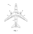
より詳細に図面を参照すると、本開示の実施は、図1に概略的に示す航空機10などの構造体の環境の中で説明され得る。しかしながら、本開示は、限定しないが、自動車、重作業車両、船舶および機械類全体を含む他の構造体に等しく応用されることを理解すべきである。
Referring to the drawings in more detail, implementations of the present disclosure may be described in the environment of a structure such as the
限定しないが、例えば翼12および胴体14などの航空機10の様々な構成要素は、構造由来の振動および音響ノイズの影響を受ける。例えば、エンジン16は、作動段階に応じて、様々な振幅および周波数で構造由来の振動および音響ノイズを生成する。加えて、航空機10が直面する空気力学的力(図示せず)が、様々な振幅および周波数で構造由来の振動および音響ノイズを生成する。
Various components of
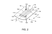
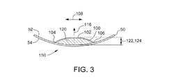
図2は、構造パネル50に結合された複合ダンパ100の実施形態の斜視図である。図3は、構造パネル50に結合された複合ダンパ100の概略横断面図である。一実施形態では、構造パネル50が航空機10の胴体14の構成要素である。別の実施形態では、構造パネル50は、翼12の1つの構成要素である。別法として、構造パネル50は、振動および/または音響ノイズの影響を受ける任意の構造体の構成要素である。図示の実施形態では、構造パネル50は湾曲したパネル構成を有する。別法として、構造パネル50は平坦なパネル構成を有する。
FIG. 2 is a perspective view of an embodiment of the
図2および図3を参照すると、図示の実施形態では、複合ダンパ100が構造パネル50の第1の面52に結合されている。パネル50は、更に第1の面52の反対側に第2の面54を含む。複合ダンパ100は、拘束シート102を含む。拘束シート102は、第1の縁部104と第2の縁部106との間に第1の方向108に延伸する。更に、第1の縁部104および第2の縁部106のそれぞれは、少なくとも部分的に第1の面52に結合されている。一実施形態では、拘束シート102は、第1の方向108に沿って全体的に湾曲した、または弓状の横断面を有する。代替の実施形態では、拘束シート102は、第1の方向108に沿って全体的に平坦な横断面を有することができる。しかしながら、拘束シート102は、第1の方向108に沿って第1の面52と一般的に同心ではなく、または第1の面52に平行ではない。
With reference to FIGS. 2 and 3, in the illustrated embodiment, the
一実施形態では、拘束シート102は、第1の縁部104および第2の縁部106の実質的に全体の範囲に沿って第1の面52に付着されている。別の実施形態では、拘束シート102は、第1の縁部104および第2の縁部106の少なくとも1つの部分的な範囲に沿ってのみ第1の面52に付着されている。複合ダンパ100が本明細書で説明するように機能できるようにする任意の適切な接着剤を使用することができる。別の実施形態では、拘束シート102は、適切な締め具を使用して、第1の縁部104および第2の縁部106に沿って第1の面52に結合される。
In one embodiment, the constraining
拘束シート102は、更に、第3の縁部110と第4の縁部112との間に第2の方向114に延伸する。拘束シート102は、第3の縁部110および第4の縁部112に沿ったどちらの側でも第1の面52に結合されていない。代替の実施形態では、第3の縁部110および第4の縁部112の少なくとも1つが一連の非連続な縁部であり、その縁部に沿って拘束シート102は第1の面52に結合されていない。
The restraining
図示の実施形態では、第1の縁部104および第2の縁部106は略直線であり、第2の方向114は第1の方向108に略直角である。更に、第2の縁部106は第1の縁部104の略反対側に配置され、第4の縁部112は第3の縁部110の略反対側に配置される。しかしながら、代替の実施形態では、第1の縁部104および第2の縁部106の少なくとも1つが湾曲している。例えば、一実施形態では、拘束シート102は略卵形ドームであり、第1の縁部104はドームの周辺の第1のセグメントを形成し、第2の縁部106は、第1のセグメントの略反対側に配置されたドームの周辺の第2のセグメントを形成する。
In the illustrated embodiment, the
第1の面52は、特定の実施形態では湾曲しているが、概ね面に垂直な方向116は、複合ダンパ100の近傍の何らかの箇所で、第1の面52に垂直な方向として定義され得る。例えば、図示の実施形態では、面に垂直な方向116は、複合ダンパ100の長手方向中心線118に沿って第1の面52に垂直な方向である。
Although the
一実施形態では、拘束シート102は、弾性材料のシートから形成される。別の実施形態では、拘束シート102は、アルミニウムの薄いシートから形成される。代替の実施形態では、拘束シート102は、複合ダンパ100が本明細書で説明するように機能することを可能にする任意のシート材料から形成される。
In one embodiment, constraining
複合ダンパ100は、更に、第1の面52と拘束シート102との間に結合された減衰層120を含む。減衰層120は、面に垂直な方向116に面の厚さ122を含み、厚さ122は、拘束シート102と第1の面52との間の第1の距離124と共に変化する。更に、減衰層120は、少なくとも部分的に粘弾性である材料から形成される。粘弾性材料は、弾性材料と比較して、サイクル負荷の下で実質的な機械的エネルギーを減衰する。加えて、少なくともいくつかの粘弾性材料は、広範囲の作動周波数の中で振動エネルギーを吸収する傾向がある。一実施形態では、減衰層120は、ポリエーテル系ポリウレタンフォームから形成される。代替の実施形態では、減衰層120は、連続気泡メラミンフォームから形成される。代替の実施形態では、減衰層120は、本明細書で説明するように複合ダンパ100が機能することを可能にする任意の材料から形成される。
一実施形態では、減衰層120は、第1の面52と接触する実質的に全体的範囲に亘って、第1の面52に付着され、拘束シート102と接触する実質的に全体的範囲に亘って、拘束シート102に付着される。別の実施形態では、減衰層120は、第1の面52および拘束シート102と接触する範囲の少なくとも部分だけに亘って、第1の面52および拘束シート102の少なくとも1つにそれぞれ付着される。本明細書で説明するように複合ダンパ100が機能することを可能にする任意の適切な接着剤が使用可能である。代替の実施形態では、減衰層120は、適切な締め具を使用して第1の面52および拘束シート102の少なくとも1つに結合される。
In one embodiment, the damping
図示の実施形態では、減衰層120は、拘束シート102の第1の縁部104と第2の縁部106との間に第1の方向108に延伸し、かつ第3の縁部110と第4の縁部112との間に第2の方向114に延伸する。別の実施形態では、減衰層120は、第3の縁部110と第4の縁部112との間に部分的にだけ延伸し、第3の縁部110および第4の縁部112の少なくとも1つを越えて延伸し、第1の縁部104と第2の縁部106との間に部分的にだけ延伸し、またはそれらの組合せである。
In the illustrated embodiment, the damping
特定の実施形態では、拘束シート102は、それを貫通して延伸する複数の穿孔128を含む。穿孔128は、減衰層120による音波の吸収を促進するように構成される。より詳細には、穿孔128は、音波が拘束層102を通過して減衰層120に入るように促進するために、適切な寸法および間隔を含み、減衰層120で音波が粘弾性材料によって吸収される。加えて、穿孔128は、穿孔のない拘束シート102と比較して、拘束シート102の重量をより軽減することにつながり、同時に穿孔のない拘束シート102と実質的に同じ機能を維持する。
In certain embodiments, the constraining
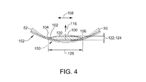
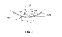
図示の目的で、図3の構造パネル50および複合ダンパ100の構成は、基準線状態150と呼ぶことにする。構造パネル50の振動の少なくともいくつかのモードは、各振動サイクルについて、構造パネル50の圧縮変形と構造パネル50の膨張変形との間の基準線状態150に対する振動として特徴づけることができる。図4は、圧縮して変形された状態152で構造パネル50に結合された複合ダンパ100の概略横断面であり、図5は、膨張して変形された状態154で構造パネル50に結合された複合ダンパ100の概略横断面である。説明を分かりやすくするために、基準線状態150(図3参照)は、図4および図5では破線で示されている。図4および図5で図示する構造パネル50の変形の大きさは、縮尺通りであることを意図せず、むしろ説明を分かりやすくするために誇張されていることに留意されたい。
For the purpose of illustration, the configuration of the
図4を参照すると、構造パネル50は振動によって圧縮して変形された状態152である間、減衰層120は圧縮応力の影響を受ける。より詳細には、拘束シート102の第1の縁部104および第2の縁部106が第1の面52に結合されているので、第1の縁部104と第2の縁部106との間の第2の距離126が、基準線状態150の各位置に対して、第1の方向108に沿って増加する。その結果、拘束シート102が第1の面52に接近して引っ張られ、第1の距離124が減少するようになる。第1の距離124が減少するにつれて、それによって厚さ122が減少し、減衰層120が、面に垂直な方向116に略平行な方向に、拘束シート102と第1の面52との間で圧縮される。
Referring to FIG. 4, while the
図5を参照すると、構造パネル50は振動によって膨張して変形された状態154である間、減衰層120は減圧応力の影響を受ける。より詳細には、拘束シート102の第1の縁部104および第2の縁部106が第1の面52に結合されているので、第1の縁部104と第2の縁部106との間の第2の距離126が、基準線状態150の各位置に対して、第1の方向108に沿って減少する。その結果、拘束シート102が第1の面52から離れて移動し、第1の距離124が増加するようになる。第1の距離124が増加するにつれて、それによって厚さ122が増加し、減衰層120が、面に垂直な方向116に略平行な方向に、拘束シート102と第1の面52との間で膨張する。
Referring to FIG. 5, while the
したがって、図3から図5を参照すると、特定の実施形態では、拘束シート102は、構造パネル50の各振動サイクルに応答して、主に面に垂直な方向116に、更に構造面52に略平行なせん断方向にも減衰層120の変形を受動的に誘発するように構成される。したがって、各振動サイクルに対して、減衰層120を圧縮および膨張するために必要な機械的エネルギーの第1の量が減衰され、減衰層120をせん断するために必要な機械的エネルギーの第2の量もまた減衰される。エネルギーの第1の量および第2の量の減衰は、構造パネル50内の振動を減衰する働きをする。減衰層120および拘束シート102向けに上記に説明する材料などの材料が、構造パネル50の幅広い温度範囲ならびに非音響および音響両方の振動周波数の幅広い範囲に亘って、複合ダンパ100による減衰を促進する。
Accordingly, with reference to FIGS. 3-5, in certain embodiments, the restraining
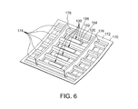
図6は、航空機10の構造パネル170の第1の面172に結合された複数の複合ダンパ100の斜視図である。より詳細には、各複合ダンパ100は、第1の縁部104および第2の縁部106に沿って第1の面172に結合された拘束シート102を含み、各対応する減衰層120が、第1の面172と各拘束シート102との間に結合されている。パネル170は、複数のストリンガ174を含み、複数のフレーム176がパネル170を横切る。図示の実施形態では、少なくとも1つの複合ダンパ100が、各対のストリンガ174の間に結合されている。更に、各複合ダンパ100は、一対のフレーム176の間に結合されている。複数の複合ダンパ100は、前述の態様で、構造パネル170の中で非音響振動および音響振動を減衰することを促進する。
FIG. 6 is a perspective view of a plurality of
図7は、構造パネル50または構造パネル170など、構造パネル内の構造振動およびノイズ伝達を低減する方法200の実施形態の流れ図である。方法200は、拘束シート102などの拘束シートの第1の縁部を少なくとも部分的に構造パネルの第1の面52または第1の面172などの第1の面に結合するステップ202を含む。方法200は、更に、拘束シートの第2の縁部を少なくとも部分的に第1の面に結合するステップ204と、減衰層120などの減衰層に粘弾性材料を提供するステップ206と、面に垂直な方向116など、第1の面に略垂直な方向に減衰層の厚さ122などの厚さが、拘束シートと第1の面との間の第1の距離124などの第1の距離と共に変化するように、拘束シートと第1の面との間に減衰層を結合するステップ208とを含む。
FIG. 7 is a flow diagram of an embodiment of a
特定の実施形態では、方法200は、更に、構造パネルが圧縮して変形された状態である場合、第1の縁部と第2の縁部との間の第2の距離126などの第2の距離が増加し、構造パネルが膨張して変形された状態である場合、第1の縁部と第2の縁部との間の第2の距離126などの第2の距離が減少するように、第1の縁部および第2の縁部を少なくとも部分的に第1の面に結合するステップ210を含む。加えて、方法200は、別法として、減衰層にポリエーテル系ポリウレタンフォーム材料を提供するステップ212、および減衰層に連続気泡メラミンフォーム材料を提供するステップ214を含む。加えて、特定の実施形態では、方法200は、接着剤を使用して、第1の縁部および第2の縁部を少なくとも部分的に第1の面に結合するステップ216を含む。加えて、方法200は、拘束シートを貫通してそれぞれ延伸する穿孔128など、複数の穿孔を設けるステップ218を含み、複数の穿孔は、音波が拘束層を通過して減衰層の中に入ることを促進するために適切な寸法および間隔を含む。
In certain embodiments, the
方法200の各工程は、システムインテグレータ、第三者、および/または顧客によって実行または実施され得る。この説明の目的のために、システムインテグレータは、限定しない任意の数の航空機製造会社および主要システム下請け業者を含むことができ、第三者は、限定しない数の売主、下請け業者および供給会社を含むことができ、顧客は、航空会社、リース会社、軍用機関、サービス組織などであることができる。更に、航空宇宙の実施例が示されているが、本発明の原理は、自動車産業などの他の産業に応用することができる。
Each step of
本明細書で説明する実施形態は、構造由来の振動および構造パネルによる音響ノイズ伝達の両方を低減するための方法および装置を提供する。実施形態は、パネル面の幅広い範囲の振動周波数に応答して、幅広い範囲の温度に亘って、パネル面に略垂直な方向、ならびにパネル面に平行な方向に減衰層内部の変形を誘発する複合ダンパを提供する。 The embodiments described herein provide methods and apparatus for reducing both structural vibrations and acoustic noise transmission by structural panels. The embodiment is a composite that induces deformation within the damping layer in a direction substantially perpendicular to the panel surface and in a direction parallel to the panel surface over a wide range of temperatures in response to a wide range of vibration frequencies of the panel surface. Provide a damper.
本明細書で説明する実施形態は、少なくともいくつかの公知の振動およびノイズ低減システムを超えた改良を提供する。少なくともいくつかの公知の振動およびノイズ低減システムと比較すると、本明細書で説明する複合ダンパは、所与の重量の減衰材料の変形潜在力のより優れた利用をもたらし、それによって、構造内に存在する増加した割合の振動エネルギーを減衰することを促進する。加えて、複合ダンパは、幅広い範囲の音響振動周波数を吸収する傾向がある材料を含む。したがって、本明細書で説明する実施形態は、構造由来の振動を減衰し、音響ノイズを吸収するために別個の装置の必要を低減し、またはその必要をなくす。加えて、本明細書で説明する方法および装置は、能動的な制御システムおよびアクチュエータを必要とせずに、受動的な方法で構造振動および音響ノイズを低減する。 The embodiments described herein provide improvements over at least some known vibration and noise reduction systems. Compared to at least some known vibration and noise reduction systems, the composite damper described herein provides a better utilization of the deformation potential of a given weight of damping material, and thereby within the structure. Helps to attenuate the increased percentage of vibrational energy present. In addition, composite dampers include materials that tend to absorb a wide range of acoustic vibration frequencies. Thus, the embodiments described herein attenuate or eliminate the need for a separate device to dampen structural vibrations and absorb acoustic noise. In addition, the methods and apparatus described herein reduce structural vibration and acoustic noise in a passive manner without the need for active control systems and actuators.
本明細書に記載する説明は、様々な実施を開示するための実施例を使用し、その実施例には、当業者が、任意の装置またはシステムを作製し、使用し、および任意の組み込まれた方法を実施することを含めて、それらの実施を実行することができるようにする最良の形態が含まれる。その特許性のある範囲は、特許請求の範囲によって定義され、当業者が思い当たる他の実施例を含むことができる。そのような他の実施例は、それらが特許請求の範囲の文言とは異ならない構造的要素を含む場合、またはそれらが特許請求の範囲の文言とは実質的に異ならない均等な構造的要素を含む場合、特許請求の範囲内にあると意図するものである。 The description provided herein uses examples to disclose various implementations, in which one of ordinary skill in the art can make, use, and arbitrarily incorporate any device or system. The best mode is included to allow those implementations to be performed, including implementing the methods described. Its patentable scope is defined by the claims, and may include other examples that occur to those skilled in the art. Such other embodiments may include structural elements that do not differ from the language of the claims, or equivalent structural elements that do not substantially differ from the language of the claims. If included, it is intended to be within the scope of the claims.
10 航空機
12 翼
14 胴体
16 エンジン
50 構造パネル
52 第1の面
54 第2の面
100 複合ダンパ
102 拘束シート
104 第1の縁部
106 第2の縁部
108 第1の方向
110 第3の縁部
112 第4の縁部
114 第2の方向
116 面に垂直な方向
118 長手方向中心線
120 減衰層
122 厚さ
124 第1の距離
126 第2の距離
128 穿孔
150 基準線状態
152 圧縮して変形された状態
154 膨張して変形された状態
170 構造パネル
172 第1の面
174 ストリンガ
176 フレーム
10 Aircraft
12 wings
14 Torso
16 engine
50 structural panels
52 First side
54 Second side
100 compound damper
102 Restraint sheet
104 First edge
106 Second edge
108 First direction
110 Third edge
112 4th edge
114 Second direction
116 direction perpendicular to the surface
118 Longitudinal centerline
120 damping layer
122 thickness
124 First distance
126 Second distance
128 drilling
150 Reference line condition
152 Compressed and deformed state
154 Inflated and deformed state
170 Structural panel
172 First side
174 Stringer
176 frames
Claims (11)
第1の縁部(104)と第2の縁部(106)との間に延伸する拘束シート(102)であって、前記第1の縁部および前記第2の縁部のそれぞれが、少なくとも部分的に前記構造パネルの第1の面(52)に結合されている拘束シートと、
前記拘束シートと前記第1の面との間に結合された減衰層(120)であって、前記構造パネルが圧縮して変形された状態(152)である場合、前記第1の面に略垂直な方向に前記減衰層の厚さが、基準線状態(150)に対して減少するようにし、前記減衰層が粘弾性材料を含む、減衰層と
を備える複合ダンパ。 A composite damper (100) for a structural panel (50),
A constraining sheet (102) extending between a first edge (104) and a second edge (106), wherein each of the first edge and the second edge is at least A constraining sheet partially bonded to the first surface (52) of the structural panel;
When the damping layer (120) coupled between the constraining sheet and the first surface is in a state (152) in which the structural panel is compressed and deformed, the first surface is substantially A composite damper comprising: a damping layer, wherein the damping layer has a thickness that decreases in a vertical direction relative to a baseline condition (150), the damping layer comprising a viscoelastic material.
拘束シート(102)の第1の縁部(104)を少なくとも部分的に前記構造パネルの第1の面(52)に結合するステップと、
前記拘束シートの第2の縁部(102)を少なくとも部分的に前記第1の面に結合するステップと、
減衰層(120)に粘弾性材料を提供するステップと、
前記拘束シートと前記第1の面との間に減衰層を結合するステップであって、前記構造パネルが圧縮して変形された状態(152)である場合、前記第1の面に略垂直な方向に前記減衰層の厚さが、基準線状態(150)に対して減少するようにするステップと
を含む方法。 A method for reducing structural vibration and noise transmission in a structural panel (50), comprising:
Coupling the first edge (104) of the restraining sheet (102) at least partially to the first surface (52) of the structural panel;
Coupling the second edge (102) of the constraining sheet at least partially to the first surface;
Providing a viscoelastic material to the damping layer (120);
A step of coupling a damping layer between the constraining sheet and the first surface, wherein the structural panel is compressed and deformed (152) and is substantially perpendicular to the first surface; Causing the thickness of the attenuation layer to decrease in a direction relative to a baseline condition (150).
Applications Claiming Priority (2)
| Application Number | Priority Date | Filing Date | Title |
|---|---|---|---|
| US14/276,703 US9725154B2 (en) | 2014-05-13 | 2014-05-13 | Method and apparatus for reducing structural vibration and noise |
| US14/276,703 | 2014-05-13 |
Publications (2)
| Publication Number | Publication Date |
|---|---|
| JP2015227724A true JP2015227724A (en) | 2015-12-17 |
| JP6476044B2 JP6476044B2 (en) | 2019-02-27 |
Family
ID=52987921
Family Applications (1)
| Application Number | Title | Priority Date | Filing Date |
|---|---|---|---|
| JP2015079851A Active JP6476044B2 (en) | 2014-05-13 | 2015-04-09 | Method and apparatus for reducing structural vibration and noise |
Country Status (5)
| Country | Link |
|---|---|
| US (1) | US9725154B2 (en) |
| EP (1) | EP2944844B1 (en) |
| JP (1) | JP6476044B2 (en) |
| CN (1) | CN105206256B (en) |
| CA (1) | CA2888551C (en) |
Families Citing this family (10)
| Publication number | Priority date | Publication date | Assignee | Title |
|---|---|---|---|---|
| US9725154B2 (en) * | 2014-05-13 | 2017-08-08 | The Boeing Company | Method and apparatus for reducing structural vibration and noise |
| US10032444B2 (en) * | 2015-06-18 | 2018-07-24 | Sveuciliste U Zagrebu Fakultet Elektrotehnike I Racunarstva | Resonator absorber with adjustable acoustic characteristics |
| WO2017096064A1 (en) * | 2015-12-03 | 2017-06-08 | Viasat, Inc. | Vibration isolation apparatuses for crystal oscillators |
| DE102016115994B4 (en) | 2016-08-29 | 2020-06-10 | Deutsches Zentrum für Luft- und Raumfahrt e.V. | Wall with an outer skin and flying object subdivided into grid fields by rear webs |
| DE102017107538A1 (en) * | 2017-04-07 | 2018-10-11 | Ipetronik Gmbh & Co. Kg | Control device and method for noise reduction of auxiliary equipment for a vehicle |
| CN108133700B (en) * | 2017-12-20 | 2020-09-25 | 南京航空航天大学 | Acoustic black hole vibration and noise reduction device |
| CN108331417A (en) * | 2018-05-25 | 2018-07-27 | 上海建顾减震科技有限公司 | A kind of universal sliding type horizontal tuned mass damper |
| US20200149926A1 (en) * | 2018-11-08 | 2020-05-14 | Hiwin Mikrosystem Corp. | Encoder With Toothed Structure and Apparatus Having the Same |
| CN111071431A (en) * | 2019-12-24 | 2020-04-28 | 重庆再升科技股份有限公司 | Low-frequency sound-absorbing noise-reducing device for aircraft cabin |
| US11554728B2 (en) * | 2020-01-16 | 2023-01-17 | GM Global Technology Operations LLC | Acoustic energy damper member for a panel |
Citations (4)
| Publication number | Priority date | Publication date | Assignee | Title |
|---|---|---|---|---|
| JPH0421730U (en) * | 1990-06-14 | 1992-02-24 | ||
| JPH10246026A (en) * | 1997-03-07 | 1998-09-14 | Shingiken:Kk | Earthquake resisting wall material |
| JP2000509468A (en) * | 1996-04-08 | 2000-07-25 | ミネソタ マイニング アンド マニュファクチャリング カンパニー | Vibration and shock damping products and methods of damping vibration and shock with such products |
| JP2001518168A (en) * | 1996-05-31 | 2001-10-09 | オウェンス コーニング | Vibration damping system |
Family Cites Families (92)
| Publication number | Priority date | Publication date | Assignee | Title |
|---|---|---|---|---|
| US1327509A (en) * | 1917-03-28 | 1920-01-06 | Harold E Yarrow | Cooling air in submarine and submersible ships |
| US1912161A (en) * | 1930-05-28 | 1933-05-30 | Maurice C Rosenblatt | Building construction |
| US2091918A (en) * | 1932-10-17 | 1937-08-31 | Joseph L Finck | Insulating material |
| US2187335A (en) * | 1937-05-06 | 1940-01-16 | Hinde & Dauch Paper Co | Composite board |
| US2326581A (en) * | 1940-03-04 | 1943-08-10 | Cleef Bros Van | Panel structure |
| US2357560A (en) * | 1941-08-09 | 1944-09-05 | Jr Frank J Taforo | Acoustical material |
| US2419971A (en) * | 1943-06-05 | 1947-05-06 | Rumpf Herman | Padding and soundproofing material |
| US2576698A (en) * | 1948-04-14 | 1951-11-27 | Johns Manville | Metal-sheathed insulating blanket and method of manufacture |
| US2924857A (en) * | 1957-01-15 | 1960-02-16 | Fenestra Inc | Sound absorbing structure |
| US2887173A (en) * | 1957-05-22 | 1959-05-19 | G A Societa Per Azioni Sa | Sound absorbing and insulating panel |
| US3215225A (en) * | 1961-11-29 | 1965-11-02 | Korfund Dynamics Corp | Laminated acoustic panels with outer metal layers, fibrous core and viscoelastic damping layer |
| DE1675567A1 (en) * | 1966-04-23 | 1971-01-07 | Hoechst Ag | Vibration-absorbing composite systems with intermediate layers of vinyl acetate / ethylene / ethylacrylate copolymers |
| DE2063768A1 (en) * | 1970-12-24 | 1972-07-13 | Volkswagenwerk Ag | Arrangement in the manner of an absorption silencer, in particular for motor vehicles |
| ES207580Y (en) * | 1971-01-11 | 1976-07-16 | Morresi | PANEL FOR THE ACOUSTIC AND CLIMATIC CONDITIONING OF ENVIRONMENTS IN GENERAL. |
| JPS5220241B2 (en) * | 1973-05-24 | 1977-06-02 | ||
| US4137992A (en) * | 1976-12-30 | 1979-02-06 | The Boeing Company | Turbojet engine nozzle for attenuating core and turbine noise |
| DK142710B (en) * | 1977-11-10 | 1980-12-29 | Elektronikcentralen | Sound absorbing structure. |
| CH639453A5 (en) * | 1978-12-11 | 1983-11-15 | Hawa Ag | COMPONENT FOR AIR SOUND INSULATION. |
| US4293053A (en) * | 1979-12-18 | 1981-10-06 | United Technologies Corporation | Sound absorbing structure |
| US4384634A (en) * | 1979-12-18 | 1983-05-24 | United Technologies Corporation | Sound absorbing structure |
| JPS57151347A (en) * | 1981-03-16 | 1982-09-18 | Nissan Motor | Reinforcing material for reinforcing board material |
| US4416349A (en) * | 1981-09-30 | 1983-11-22 | The Boeing Company | Viscoelastically damped reinforced skin structures |
| US4433751A (en) * | 1981-12-09 | 1984-02-28 | Pratt & Whitney Aircraft Of Canada Limited | Sound suppressor liner |
| US4741945A (en) * | 1986-07-30 | 1988-05-03 | Arco Chemical Company | Automotive trim panel |
| US4826106A (en) * | 1987-02-18 | 1989-05-02 | Grumman Aerospace Corporation | Advanced composite aircraft cowl |
| US4848514A (en) * | 1987-10-06 | 1989-07-18 | Uas Support, Inc. | Sound attenuation system for jet aircraft engines |
| US4926963A (en) * | 1987-10-06 | 1990-05-22 | Uas Support, Inc. | Sound attenuating laminate for jet aircraft engines |
| JPH0818522B2 (en) * | 1987-12-28 | 1996-02-28 | 本田技研工業株式会社 | Damping laminated material for vehicles |
| US5014815A (en) * | 1989-06-26 | 1991-05-14 | Grumman Aerospace Corporation | Acoustic liner |
| US5087491A (en) * | 1990-02-09 | 1992-02-11 | The United States Of America As Represented By The Secretary Of The Navy | Vibration-damping structural member |
| FR2664418B1 (en) * | 1990-07-09 | 1992-10-23 | Bertin & Cie | DEVICE FOR ABSORBING ACOUSTIC ENERGY EMITTED WITHIN A SHIP HULL AND MODULAR ACOUSTIC SCREEN FORMING PART OF SUCH A DEVICE. |
| US5300355A (en) * | 1991-05-31 | 1994-04-05 | Nichias Corporation | Vibration damping material |
| US5256223A (en) * | 1991-12-31 | 1993-10-26 | The Center For Innovative Technology | Fiber enhancement of viscoelastic damping polymers |
| US5298694A (en) * | 1993-01-21 | 1994-03-29 | Minnesota Mining And Manufacturing Company | Acoustical insulating web |
| JP2640078B2 (en) * | 1993-02-08 | 1997-08-13 | 株式会社神戸製鋼所 | Damping profiles and structures for transport aircraft |
| US5485053A (en) * | 1993-10-15 | 1996-01-16 | Univ America Catholic | Method and device for active constrained layer damping for vibration and sound control |
| US6021612A (en) * | 1995-09-08 | 2000-02-08 | C&D Technologies, Inc. | Sound absorptive hollow core structural panel |
| US6287664B1 (en) * | 1997-11-14 | 2001-09-11 | William F. Pratt | Continuous wave composite viscoelastic elements and structures |
| US5965853A (en) * | 1997-03-31 | 1999-10-12 | Ppg Industries Ohio, Inc. | Sound absorbing aircraft transparency and method of making same |
| AU8991898A (en) * | 1997-09-05 | 1999-03-29 | 1... Limited | Aerogels, piezoelectric devices, and uses therefor |
| US6609754B2 (en) * | 1997-09-24 | 2003-08-26 | Arjuna Indraeswaran Rajasingham | Easy ejector seat with skeletal crash safety beam |
| US6029962A (en) * | 1997-10-24 | 2000-02-29 | Retama Technology Corporation | Shock absorbing component and construction method |
| US6700304B1 (en) * | 1999-04-20 | 2004-03-02 | Virginia Tech Intellectual Properties, Inc. | Active/passive distributed absorber for vibration and sound radiation control |
| US8138908B2 (en) * | 2002-04-01 | 2012-03-20 | Arjuna Indraeswaran Rajasingham | Easy ejector seat with skeletal crash safety beam |
| US6669553B2 (en) * | 2000-02-21 | 2003-12-30 | Albert G. Adams | Noise suppression and sound proof chamber |
| US6826285B2 (en) * | 2000-08-03 | 2004-11-30 | New Transducers Limited | Bending wave loudspeaker |
| GB2365945B (en) * | 2000-08-16 | 2004-02-11 | Rolls Royce Plc | A vibration damping system and a method of damping vibrations |
| WO2002016122A1 (en) * | 2000-08-25 | 2002-02-28 | Massachusetts Institute Of Technology | A panel with two-dimensional curvature |
| EP1221574B2 (en) * | 2001-01-09 | 2017-12-20 | Mitsubishi Heavy Industries, Ltd. | Gas turbine combustor |
| DE10119037C2 (en) * | 2001-04-18 | 2003-06-26 | Dieter Braun | Curved insulating element |
| DE10154526B4 (en) * | 2001-06-12 | 2007-02-08 | Physik Instrumente (Pi) Gmbh & Co | Piezoelectric actuator |
| US20030019170A1 (en) * | 2001-07-27 | 2003-01-30 | Donnelly Thomas F. | Sound barrier wall system |
| SE0103002D0 (en) * | 2001-09-10 | 2001-09-10 | Trelleborg Ab | Vibration damping material |
| US7318873B2 (en) * | 2002-03-29 | 2008-01-15 | Zephyros, Inc. | Structurally reinforced members |
| US8376261B2 (en) * | 2002-11-01 | 2013-02-19 | Airbus Uk Limited | Landing gear |
| JP4489756B2 (en) * | 2003-01-22 | 2010-06-23 | ヴァスト・パワー・システムズ・インコーポレーテッド | Energy conversion system, energy transfer system, and method of controlling heat transfer |
| US6764754B1 (en) * | 2003-07-15 | 2004-07-20 | The Boeing Company | Composite material with improved damping characteristics and method of making same |
| CN1601023A (en) * | 2003-09-23 | 2005-03-30 | 汪荣勋 | Building blocks for forming wall body, formed wall body and usage of building blocks |
| US20050098379A1 (en) * | 2003-10-09 | 2005-05-12 | Takahiko Sato | Noise absorbing structure and noise absorbing/insulating structure |
| DE602005005160T2 (en) * | 2004-01-05 | 2009-03-26 | Airbus Deutschland Gmbh | Insulation structure for the interior insulation of a vehicle |
| EP1701883A1 (en) * | 2004-01-05 | 2006-09-20 | Airbus Deutschland GmbH | Insulation package arrangement for insulating the interior of an aircraft fuselage |
| DE102004001080A1 (en) * | 2004-01-05 | 2005-08-04 | Airbus Deutschland Gmbh | Arrangement for the interior lining of a passenger cabin of an aircraft |
| US7513082B2 (en) * | 2004-02-09 | 2009-04-07 | Lahnie Johnson | Sound reducing system |
| US20050194210A1 (en) * | 2004-03-08 | 2005-09-08 | The Boeing Company | Apparatus and method for aircraft cabin noise attenuation via non-obstructive particle damping |
| US7083147B2 (en) * | 2004-03-11 | 2006-08-01 | The Boeing Company | Modularized insulation, systems, apparatus, and methods |
| US20050198904A1 (en) * | 2004-03-12 | 2005-09-15 | Browne Alan L. | Active seal assemblies for movable windows |
| US20110226897A1 (en) * | 2004-03-19 | 2011-09-22 | Padavano Joseph F | Launch vehicle fairing and construction |
| NZ551301A (en) * | 2004-04-15 | 2011-01-28 | Philippe Pierre Marie Joseph Doneux | A construction panel laminate including a viscoelastic acoustic barrier material layer affixed to a flat construction panel |
| US7419031B2 (en) * | 2005-11-04 | 2008-09-02 | The Boeing Company | Integrally damped composite aircraft floor panels |
| US7837147B2 (en) * | 2005-03-18 | 2010-11-23 | The Boeing Company | Systems and methods for reducing noise in aircraft fuselages and other structures |
| DE102005027314A1 (en) * | 2005-06-13 | 2006-12-14 | Müller, Ulrich, Dr.-Ing. | Lightweight construction plate manufacturing method for e.g. gas turbine, involves providing face sheet, where construction plate receives defined surface curvature during connection of face sheet, intermediate layer and support layer |
| US8136835B2 (en) * | 2005-07-21 | 2012-03-20 | Arjuna Indraeswaran Rajasingham | Easy ejector seat with skeletal crash safety beam |
| US7618306B2 (en) * | 2005-09-22 | 2009-11-17 | 3M Innovative Properties Company | Conformable abrasive articles and methods of making and using the same |
| US20070069080A1 (en) * | 2005-09-28 | 2007-03-29 | The Boeing Company | Laminated passenger window with a vacuum layer for reduced noise transmission |
| US20100021686A1 (en) * | 2006-04-04 | 2010-01-28 | Francois Groussard | Sandwich panel |
| US7784165B2 (en) * | 2006-04-19 | 2010-08-31 | Material Science Corporation | Method of forming a panel constrained layer damper treatment |
| US20110139542A1 (en) * | 2006-05-23 | 2011-06-16 | Bellmax Acoustic Pty Ltd | Acoustic shield |
| US20070284185A1 (en) * | 2006-06-07 | 2007-12-13 | Foss Gary C | Damped structural panel and method of making same |
| US7779960B2 (en) * | 2006-08-18 | 2010-08-24 | Hewlett-Packard Development Company, L.P. | System and method for noise suppression |
| US9511571B2 (en) * | 2007-01-23 | 2016-12-06 | The Boeing Company | Composite laminate having a damping interlayer and method of making the same |
| FR2912100B1 (en) * | 2007-02-06 | 2009-05-08 | Cera | ACOUSTIC PROTECTION PANEL FOR MOTOR VEHICLE COMPRISING AN IMPREGNATED SEAL LAYER |
| US7987645B2 (en) * | 2007-03-29 | 2011-08-02 | Serious Materials, Inc. | Noise isolating underlayment |
| US8951923B2 (en) * | 2007-05-23 | 2015-02-10 | The Boeing Company | Hybrid composite structure having damped metallic fibers |
| KR100793074B1 (en) * | 2007-09-06 | 2008-01-10 | 김부열 | Panel for construction for reducing noise between floors having air purification and sterilizing functions |
| US8540921B2 (en) * | 2008-11-25 | 2013-09-24 | The Boeing Company | Method of forming a reinforced foam-filled composite stringer |
| US9366310B2 (en) * | 2009-02-19 | 2016-06-14 | Magna Steyr Fahrzeugtechnik Ag & Co. Kg | Planar component with vibration damping |
| JP5834007B2 (en) * | 2009-08-11 | 2015-12-16 | シロー インダストリーズ インコーポレイテッド | Metal panel assembly |
| EP2500118A4 (en) * | 2009-11-13 | 2015-06-24 | Sumitomo Light Metal Ind | Plate material having concave/convex sections, and laminate structure and vehicle panel using said plate material |
| US9644697B2 (en) * | 2009-12-21 | 2017-05-09 | Fm Energie Gmbh & Co. Kg | Eccentric clamping bushing |
| US8796164B2 (en) * | 2010-12-28 | 2014-08-05 | Cytec Technology Corp. | Multilayer and composition gradient structures with improved damping properties |
| US8770343B2 (en) * | 2011-11-23 | 2014-07-08 | The Boeing Company | Noise reduction system for composite structures |
| US9725154B2 (en) * | 2014-05-13 | 2017-08-08 | The Boeing Company | Method and apparatus for reducing structural vibration and noise |
-
2014
- 2014-05-13 US US14/276,703 patent/US9725154B2/en active Active
-
2015
- 2015-04-02 EP EP15162435.0A patent/EP2944844B1/en active Active
- 2015-04-09 JP JP2015079851A patent/JP6476044B2/en active Active
- 2015-04-14 CA CA2888551A patent/CA2888551C/en active Active
- 2015-04-27 CN CN201510204643.2A patent/CN105206256B/en active Active
Patent Citations (4)
| Publication number | Priority date | Publication date | Assignee | Title |
|---|---|---|---|---|
| JPH0421730U (en) * | 1990-06-14 | 1992-02-24 | ||
| JP2000509468A (en) * | 1996-04-08 | 2000-07-25 | ミネソタ マイニング アンド マニュファクチャリング カンパニー | Vibration and shock damping products and methods of damping vibration and shock with such products |
| JP2001518168A (en) * | 1996-05-31 | 2001-10-09 | オウェンス コーニング | Vibration damping system |
| JPH10246026A (en) * | 1997-03-07 | 1998-09-14 | Shingiken:Kk | Earthquake resisting wall material |
Also Published As
| Publication number | Publication date |
|---|---|
| CA2888551C (en) | 2018-09-04 |
| US20160185442A1 (en) | 2016-06-30 |
| CN105206256B (en) | 2020-11-03 |
| JP6476044B2 (en) | 2019-02-27 |
| CA2888551A1 (en) | 2015-11-13 |
| CN105206256A (en) | 2015-12-30 |
| EP2944844A2 (en) | 2015-11-18 |
| EP2944844B1 (en) | 2019-08-28 |
| EP2944844A3 (en) | 2016-01-20 |
| US9725154B2 (en) | 2017-08-08 |
Similar Documents
| Publication | Publication Date | Title |
|---|---|---|
| JP6476044B2 (en) | Method and apparatus for reducing structural vibration and noise | |
| EP2711922B1 (en) | Acoustic damping device for noise reduction | |
| Rao | Recent applications of viscoelastic damping for noise control in automobiles and commercial airplanes | |
| Ghiringhelli et al. | Improvement of structures vibroacoustics by widespread embodiment of viscoelastic materials | |
| US8550397B2 (en) | Acoustically attenuated fuselage for aircraft | |
| CA2936290C (en) | Multilayer panel for soundproofing aircraft interiors | |
| US8479880B2 (en) | Multifunctional nano-skin articles and methods | |
| US8770343B2 (en) | Noise reduction system for composite structures | |
| KR20140130104A (en) | Aircraft interior trim panel, and aircraft fitted with such panels | |
| US8127889B1 (en) | Noise reduction system for structures | |
| JP7316037B2 (en) | Anti-resonance panel and manufacturing method thereof | |
| US20070284185A1 (en) | Damped structural panel and method of making same | |
| KR101752653B1 (en) | Dynamic vibration absorber systen for low frequency sound insulation | |
| Hambric et al. | Quieting a rib-framed honeycomb core sandwich panel for a rotorcraft roof | |
| US20170291681A1 (en) | Composite insulation for reducing broadband aircraft noise | |
| JP2016033006A (en) | Methods and systems for damping cabin air compressor inlet | |
| He et al. | Effects of external and gap mean flows on sound transmission through a double-wall cylindrical shell lined with poroelastic materials | |
| US20130202874A1 (en) | Lightweight syntactic foams for blast mitigation in thermal/acoustic flooring | |
| Tewes | Active trim panel attachments for control of sound transmission through aircraft structures | |
| Zhou | Sound transmission through panels and shells filled with porous material in the presence of external flow | |
| Zverev et al. | Investigation of the efficiency of application of a vibration-absorbing material with a reinforcing layer for improving sound insulation of structural elements of the fuselage | |
| Xue et al. | Structural vibration damping by the use of poro-elastic layers: a summary | |
| CN109178292A (en) | A kind of mute type aircraft | |
| Xue | Structural vibration reduction achieved by lightweight porous layers through the near-field damping effect: A technical summary | |
| Aloufi | Modeling and Design of a Smart Double-Panel System for the Control of Sound Transmission Into Aircraft Cabin |
Legal Events
| Date | Code | Title | Description |
|---|---|---|---|
| A621 | Written request for application examination |
Free format text: JAPANESE INTERMEDIATE CODE: A621 Effective date: 20180406 |
|
| TRDD | Decision of grant or rejection written | ||
| A01 | Written decision to grant a patent or to grant a registration (utility model) |
Free format text: JAPANESE INTERMEDIATE CODE: A01 Effective date: 20190104 |
|
| A61 | First payment of annual fees (during grant procedure) |
Free format text: JAPANESE INTERMEDIATE CODE: A61 Effective date: 20190204 |
|
| R150 | Certificate of patent or registration of utility model |
Ref document number: 6476044 Country of ref document: JP Free format text: JAPANESE INTERMEDIATE CODE: R150 |
|
| R250 | Receipt of annual fees |
Free format text: JAPANESE INTERMEDIATE CODE: R250 |
|
| R250 | Receipt of annual fees |
Free format text: JAPANESE INTERMEDIATE CODE: R250 |
|
| R250 | Receipt of annual fees |
Free format text: JAPANESE INTERMEDIATE CODE: R250 |