JP2015225701A - Press fit terminal - Google Patents
Press fit terminal Download PDFInfo
- Publication number
- JP2015225701A JP2015225701A JP2014107936A JP2014107936A JP2015225701A JP 2015225701 A JP2015225701 A JP 2015225701A JP 2014107936 A JP2014107936 A JP 2014107936A JP 2014107936 A JP2014107936 A JP 2014107936A JP 2015225701 A JP2015225701 A JP 2015225701A
- Authority
- JP
- Japan
- Prior art keywords
- hole
- press
- fit terminal
- insertion guide
- rigidity
- Prior art date
- Legal status (The legal status is an assumption and is not a legal conclusion. Google has not performed a legal analysis and makes no representation as to the accuracy of the status listed.)
- Pending
Links
Images

Landscapes
- Coupling Device And Connection With Printed Circuit (AREA)
Abstract
Description
本明細書に開示される技術は、プレスフィット端子に関する。 The technology disclosed in this specification relates to a press-fit terminal.
従来、電子機器に組み込まれる配線基板120のスルーホール121に圧入され、導電回路と半田付けを行うことなく導通接続されるとともに、配線基板120に機械的に接触固定されるプレスフィット端子100が知られている(図7参照)。
2. Description of the Related Art Conventionally, there is known a press-
プレスフィット端子100は、タブ状端子の幅方向の中央部にスリット部107を設けるとともに、スリット部107を挟んで互いに対向する一対の梁部材102のうち、最も外幅が大きい接触部104の外縁部間の幅をスルーホール121の内径よりも大きく設定し、梁部材102をスリット部107内に撓ませながらスルーホール121内に圧入することにより、スルーホール121内の導電膜と弾性的に接触させて、導通接続させるようになっている(図8参照)。
The press-
このようなプレスフィット端子100は、振動等の外力により配線基板120から離脱しないように、配線基板120に対して一定以上の保持力を確保することが重要である。
It is important for such a press-
ところで、車載用の電子機器は更なる小型化が要望されており、プレスフィット端子も、従来よりも小径のスルーホールに対応すべく、小型化が求められている。しかし、上述した従来のプレスフィット端子100を単に小型化すると、小型プレスフィット端子およびスルーホール間の接触荷重が低下し、それに伴って保持力が低下する傾向がある。
By the way, further miniaturization is demanded for in-vehicle electronic devices, and the press-fit terminals are also required to be miniaturized in order to cope with through holes having a smaller diameter than before. However, when the conventional press-
すなわち、従来のプレスフィット端子100はある程度の板厚を有していたため、配線基板120のスルーホール121に挿入された際に、一定以上の接触荷重を得ることが可能であった。しかし、従来型を単に小型化したプレスフィット端子では、端子の板厚が薄くなるため、弾性力が低下し、接触荷重が低下する。
That is, since the conventional press-
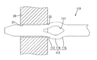
そこで、一定以上の接触荷重を確保するために、例えば図9に示すように、スルーホール21の径に対する架橋部112の幅W0の割合を従来型より大きく、すなわち、架橋部112の幅W0を広くして、架橋部112の剛性を高くすることが考えられる。
Therefore, in order to ensure a certain contact load or more, for example, as shown in FIG. 9, the ratio of the width W0 of the
しかしそのようにすると、図10および図11に示すように、プレスフィット端子110のスルーホール21への圧入時に、架橋部112の先端側が強い力を受けて絞られるように大きく変形する一方、逆に後方側は充分に撓み難くなり、その結果、架橋部112とスルーホール21との接触位置P1が、スルーホール21の中央部P0より後方側へと移動してしまう虞がある。
However, when doing so, as shown in FIGS. 10 and 11, when the press-
このような、プレスフィット端子110のスルーホール21への圧入時の変形による接触位置の移動は、スルーホール21の径が小さくなる程、発生し易い。また、このように接触位置に移動が生じた場合、保持力特性は、接触位置がプレスフィット端子110の後方側へずれる分、引き抜き距離が短くなってしまうため、低下する。すなわち、少し引き抜かれただけで保持力が急減し、プレスフィット端子110が回路基板20から離脱してしまう懸念がある。
Such movement of the contact position due to deformation during press-fitting of the press-
本明細書に開示される技術は、小型化しても十分な保持力が得られるプレスフィット端子を提供することを目的とするものである。 The technology disclosed in this specification is intended to provide a press-fit terminal that can obtain a sufficient holding force even if it is downsized.
本明細書に開示される技術は、回路基板に設けられたスルーホール内に貫通され、前記スルーホールの内壁に対して弾性的に接触することにより前記スルーホール内に設けられた導電膜と導通接続されるプレスフィット端子であって、先端側に位置する挿入案内部と、該挿入案内部の反対側に位置する基部と、前記挿入案内部および前記基部の間に位置して両者を連結するとともに、外向きに張り出して前記スルーホールの内壁に対して弾性的に接触する一対の架橋部と、を備え、前記一対の架橋部のうち前記基部側の剛性が、前記挿入案内部側の剛性よりも低く設定されていることを特徴とする。 The technology disclosed in this specification is penetrated into a through hole provided in a circuit board and is electrically connected to a conductive film provided in the through hole by elastically contacting the inner wall of the through hole. A press-fit terminal to be connected, which is an insertion guide part located on the distal end side, a base part located on the opposite side of the insertion guide part, and located between the insertion guide part and the base part to couple them together. And a pair of bridging portions that project outward and elastically contact the inner wall of the through hole, and the rigidity of the base portion side of the pair of bridging portions is the rigidity of the insertion guide portion side. It is characterized by being set lower.
上記構成によれば、一対の架橋部のうち基部側の剛性が挿入案内部側の剛性よりも低く設定されているので、基部側が撓み易くなり、もって、プレスフィット端子をスルーホールに圧入した際に、スルーホールとプレスフィット端子との接触位置がスルーホールの中央部から基部側へ移動しないようになる。これにより、十分な保持力が得られる。 According to the above configuration, since the rigidity on the base side of the pair of bridging parts is set lower than the rigidity on the insertion guide part side, the base side is easily bent, and thus when the press-fit terminal is press-fitted into the through hole. In addition, the contact position between the through hole and the press-fit terminal does not move from the center portion of the through hole to the base side. Thereby, sufficient holding force is obtained.
上記構成の具体的態様の一例として、一対の架橋部を、先端側から後方側に向けて外向きに傾斜する第1変形部と、後方側から先端側に向けて外向きに傾斜する第2変形部と、を備える略山形に張り出す構成とし、第2変形部の剛性を第1変形部の剛性よりも低く設定してもよい。 As an example of a specific aspect of the above configuration, the pair of bridging portions includes a first deforming portion that inclines outward from the tip side toward the rear side, and a second that inclines outward from the rear side toward the tip side. The second projecting portion may be configured to project in a substantially mountain shape including the deforming portion, and the rigidity of the second deforming portion may be set lower than that of the first deforming portion.
また、第1変形部および第2変形部の間に、挿入案内部の軸方向に沿って延びる接触部を設ける構成としてもよい。このような構成とすると、架橋部とスルーホールとの接触面積が広くなるので、より確実に導通接続が行われる。 Moreover, it is good also as a structure which provides the contact part extended along the axial direction of an insertion guide part between a 1st deformation part and a 2nd deformation part. With such a configuration, the contact area between the bridging portion and the through hole is increased, so that the conductive connection is more reliably performed.
また、第2変形部の剛性を第1変形部の剛性よりも低く設定する具体的態様としては、第2変形部の幅を第1変形部の幅よりも小さく設定したり、第2変形部の長さを、第1変形部の長さよりも長く設定したりすることが好ましい。 In addition, as a specific mode in which the rigidity of the second deformable portion is set lower than the rigidity of the first deformable portion, the width of the second deformable portion is set smaller than the width of the first deformable portion, or the second deformable portion Is preferably set longer than the length of the first deformable portion.
さらに、一対の架橋部間に位置する孔部を、挿入案内部よりも基部側に偏って配することにより、一対の架橋部のうち基部側の剛性を挿入案内部側の剛性よりも低く設定することができる。 Furthermore, by arranging the hole located between the pair of bridging portions so as to be biased to the base side relative to the insertion guide portion, the rigidity on the base side of the pair of bridging portions is set lower than the rigidity on the insertion guide portion side. can do.
本明細書に開示される技術によれば、小型化しても十分な保持力特性を有するプレスフィット端子が得られる。 According to the technique disclosed in the present specification, a press-fit terminal having sufficient holding force characteristics can be obtained even if it is downsized.
<実施形態1>
実施形態1を図1ないし図4によって説明する。
<Embodiment 1>
The first embodiment will be described with reference to FIGS.
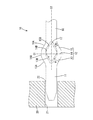
プレスフィット端子10は、回路基板20のスルーホール21に圧入されるものであって、銅合金等の導電性に優れた金属板材をプレス加工することにより、細長いタブ状に形成されている。
The press-
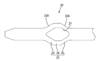
プレスフィット端子10は、図1に示すように、一端側が回路基板20のスルーホール21へ案内するための先細の挿入案内部11とされ、他方側は他の端子等と接続される図示しない接続部に繋がる基部16とされている。挿入案内部11と基部16との間には、両者を連結する一対の架橋部12が設けられている。これらの挿入案内部11、一対の架橋部12、および基部16は、全て同等の板厚とされている。以下、スルーホール21への挿入方向を前方、その反対方向を後方として説明する。
As shown in FIG. 1, the press-
一対の架橋部12の外側の縁部は、それぞれ外側に向けて略山形に張り出しており、前方側の傾斜部が第1変形部13、後方側の傾斜部が第2変形部15とされている。第1変形部13および第2変形部15の間には、プレスフィット端子10(挿入案内部11)の軸方向、すなわち、前後方向に沿って延びる接触部14が設けられている。
The outer edge portions of the pair of bridging
一の第1変形部13の外側の縁部である第1外縁部13Aと、この一の第1変形部13と接触部14を介して隣り合う第2変形部15の外側の縁部である第2外縁部15Aとは、架橋部12をプレスフィット端子10の軸と直交する中心線C1で二つに折り曲げた場合に、ぴったり折り重なるように、線対象の関係とされている。すなわち、一の架橋部12の外側の縁部(第1外縁部13Aおよび第2外縁部15A)は、図1において、左右線対称の傾斜状とされている。
13A of 1st outer edge parts which are the outer edge parts of one 1st deformation |
なお、接触部14の外側の縁部は、第3外縁部14Aとよぶこととする。
The outer edge portion of the
また一対の架橋部12は、プレスフィット端子10をその軸に沿った中心線C2で二つに折り曲げた場合に、ぴったり折り重なるように線対称の関係とされている。すなわち、一対の架橋部12は、図1において、上下線対称の形状とされている。
Further, the pair of
一対の架橋部12の間は、略菱形状の孔部17とされている。孔部17の内側の縁部は、図1に示すように、一対の架橋部12の第1外縁部13A、第3外縁部14A、および、第2外縁部15Aとそれぞれ平行に設けた第1内縁部13B、第3内縁部14B、第2内縁部15Bとされている。
Between the pair of
本実施形態においては、第1変形部13および第2変形部15の各幅が、異なるように設定されている。より詳細には、図1に示すように、第1外縁部13Aから第1内縁部13Bまでの距離(幅W1)と、第2外縁部15Aから第2内縁部15Bまでの距離(幅W2)W2とは、異なるように設定されており、W1>W2とされている。すなわち、第2変形部15の剛性が、第1変形部13の剛性よりも低くなるように設定されている。
In the present embodiment, the widths of the
このような形状は、例えば、図9に示すような、本実施形態のプレスフィット端子10と等しい外形を有し、かつ、架橋部112全体が同幅W0とされた形状のプレスフィット端子110の孔部117を、プレスフィット端子110の軸方向に沿って後方側に移動した状態とすることにより、形成することができる(図1参照)。
Such a shape has, for example, a press-
このように形成された本実施形態のプレスフィット端子10の第1変形部13の幅W1は、図9に示すプレスフィット端子110の第1変形部113の幅W0よりも大きくなる(W1>W0)。また、第2変形部15の幅W2は、図9に示すプレスフィット端子110の第2変形部115の幅W0よりも小さくなる(W2<W0)。
The width W1 of the
また、このように形成された本実施形態のプレスフィット端子10において、孔部17の前端は、第1外縁部13Aの前端より後方側に配されるとともに、孔部17の後端は、第2外縁部15Aの後端より後方側に配されている。
Further, in the press-
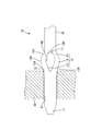
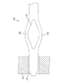
次に、本実施形態のプレスフィット端子10の作用について説明する。プレスフィット端子10を回路基板20のスルーホール21内に挿入案内部11側から挿入すると、まず、一対の架橋部12のうち第1変形部13の第1外縁部13Aがスルーホール21の開口縁部22に突き当たる。プレスフィット端子10をスルーホール21内にさらに挿入すると、スルーホール21の開口縁部22に第1外縁部13Aが押圧されることより、第1変形部13が孔部17内に徐々に撓みながらスルーホール21内に進入する(図2参照)。
Next, the effect | action of the press
そして、一対の架橋部12の接触部14の先端縁がスルーホール21の開口縁部22を通り過ぎると、接触部14の第3外縁部14Aがスルーホール21の内壁に押し付けられた状態となる。さらに、接触部14の後端縁がスルーホール21の開口縁部22を通り過ぎるまで押し込むことにより、スルーホール21内の導電膜とプレスフィット端子10(接触部14)とが導通接続される。(図3参照)。
And if the front-end edge of the
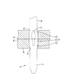
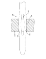
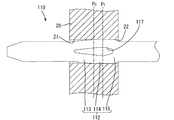
ところで、例えば図9に示すような、本実施形態のプレスフィット端子10と外形が等しく、架橋部112全体が、適度な接触荷重が得られる同幅W0に設定されたプレスフィット端子110においては、スルーホール21へ圧入する際、図10および図11に示すように、先に挿入される第1変形部113が先に孔部117内に撓み、その後、接触部114が孔部117内に撓んだ後、第1変形部113と同等の剛性を有する第2変形部115は孔部117内にうまく撓むことができないという問題が生じる。
By the way, for example, as shown in FIG. 9, in the press
すなわち、架橋部112の幅W0がスルーホール21の孔径に対してある程度以上大きく設定された場合には、架橋部112全体が均等に撓むのではなく、先に挿入される第1変形部113に大きな力がかかって過剰に変形され、逆に、後方側に配された第2変形部115は容易に撓むことができなくなる。その結果、図11に示すように、プレスフィット端子110とスルーホール21との接触位置P1が、本来の接触位置P0(スルーホール21の中央)よりも、スルーホール21の挿入側の開口縁部22側(後方側)に移動する。
That is, when the width W0 of the bridging
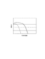
このように、接触位置Pが移動した場合のプレスフィット端子110の保持力特性は、接触位置Pが移動した分、短い距離の移動(引き抜き)でプレスフィット端子110の接触荷重が失われて抜けが発生するため、図4に示すように、接触位置が移動しない場合(図4の実線)と比較して大きく低下してしまう(図4の破線)。
As described above, the holding force characteristic of the press-
このような問題に対し、本実施形態のプレスフィット端子10によれば、第2変形部15の幅W2を第1変形部13の幅W1と比較して小さく設定する(W1>W2)ことにより、第2変形部15の剛性を第1変形部13の剛性より低く設定し、容易に撓むことが可能な構成とされている。
For such a problem, according to the press-
すなわち、第1変形部13において幅W1を大きくして剛性を高くすることにより接触荷重を十分に確保しながらも、第2変形部15において幅W2を小さくして剛性を低くすることにより撓み易くし、接触位置P2がスルーホール21の挿入側の開口縁部22側(後方側)に移動することを抑制した。もって、高い保持力特性を得ることができる。
That is, it is easy to bend by making width W2 small and making rigidity low in the
<実施形態2>
実施形態2について図5を参照して説明する。以下、実施形態1と同じ部位については同じ用語を用い、詳細な説明を省略する。
<Embodiment 2>
A second embodiment will be described with reference to FIG. Hereinafter, the same parts as those in the first embodiment are used, and detailed description thereof is omitted.
本実施形態のプレスフィット端子30は、図9に示すような、架橋部112全体が同幅W0に設定されたプレスフィット端子110の第2変形部115の幅を単に細くすることにより、第2変形部35の剛性を第1変形部33の剛性よりも低くする構成としたものである。
As shown in FIG. 9, the press-
このプレスフィット端子30において、孔部37の前端は、第1外縁部33Aの前端とほぼ同じ位置に配されるとともに、孔部37の後端は、第2外縁部35Aの後端とほぼ同じ位置かやや後方側に配される(図5参照)ところが、上記実施形態1のプレスフィット端子10と異なる。
In the press-
本実施形態のプレスフィット端子30においても、第2変形部35の剛性は第1変形部33の剛性よりも低く設定されているから、第2変形部35が撓み易くなっており、接触位置Pがスルーホール21の挿入側の開口縁部22側(後方側)に移動することが抑制される。もって、高い保持力特性を得ることができる。
Also in the press
<実施形態3>
実施形態3について図6を参照して説明する。以下、実施形態1と同じ部位については同じ用語を用い、詳細な説明を省略する。
<Embodiment 3>
A third embodiment will be described with reference to FIG. Hereinafter, the same parts as those in the first embodiment are used, and detailed description thereof is omitted.
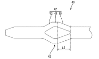
本実施形態のプレスフィット端子40は、図9に示すような、架橋部112全体が同幅W0に設定されたプレスフィット端子110の第2変形部115の、前後方向の長さL1を長くすることにより、第2変形部45の剛性を第1変形部43の剛性よりも低くする構成としたものである。すなわち、第2変形部45の前後方向の長さをL2とすると、L1<L2とされている。なお、本実施形態のプレスフィット端子40の第2変形部15の前後方向の長さは、図9に示すプレスフィット端子110の第1変形部113の前後方向の長さL1と同等である。
In the press-
本実施形態のプレスフィット端子40においても、第2変形部45の剛性は第1変形部43の剛性よりも低くされているから、第2変形部45が撓み易くなっており、接触位置Pがスルーホール21の挿入側の開口縁部22側(後方)に移動することが抑制される。もって、高い保持力特性を得ることができる。
Also in the press-
<他の実施形態>
本明細書に記載される技術は、上記記述及び図面によって説明した実施形態に限定されるものではなく、例えば次のような実施形態も技術的範囲に含まれる。
<Other embodiments>
The technology described in the present specification is not limited to the embodiment described with reference to the above description and drawings. For example, the following embodiments are also included in the technical scope.
(1)上記実施形態では、一対の架橋部12,32,42が、第1変形部13,33,43、接触部14,34,44、および、第2変形部15,35,45、を備えた略山形の構成を示したが、例えば、接触部を備えない略山形の構成としてもよい。そのような構成とした場合には、プレスフィット端子とスルーホールとは、線接触するようになる。
(1) In the above embodiment, the pair of bridging
(2)一対の架橋部は、略山形ではなく、例えば円弧状等、他の形態とすることもできる。 (2) The pair of bridging portions is not substantially mountain-shaped, but may be other forms such as an arc shape.
(3)一対の架橋部の剛性は、上記実施形態に限らず、例えば、挿入案内部から基部側へ向けて連続的に幅を小さくすることにより、基部側の方を低くする等の構成とすることもできる。 (3) The rigidity of the pair of bridging portions is not limited to the above embodiment. For example, the width of the base portion side is lowered by continuously reducing the width from the insertion guide portion toward the base side. You can also
10,30,40,110…プレスフィット端子
11…挿入案内部
12,32,42,112…架橋部
13,33,43,113…第1変形部
14,34,44,114…接触部
15,35,45,115…第2変形部
16…基部
17,37…孔部
20…回路基板
21…スルーホール
22…開口縁部
C1,C2…中心線
L1,L2…長さ
W0,W1,W2…幅
P0,P1,P2……接触位置
10, 30, 40, 110 ... press-
Claims (6)
先端側に位置する挿入案内部と、該挿入案内部の反対側に位置する基部と、
前記挿入案内部および前記基部の間に位置して両者を連結するとともに、外向きに張り出して前記スルーホールの内壁に対して弾性的に接触する一対の架橋部と、を備え、
前記一対の架橋部のうち前記基部側の剛性が、前記挿入案内部側の剛性よりも低く設定されているプレスフィット端子。 A press-fit terminal that is penetrated into a through-hole provided in a circuit board and is electrically connected to a conductive film provided in the through-hole by elastically contacting the inner wall of the through-hole;
An insertion guide part located on the distal end side, a base part located on the opposite side of the insertion guide part,
A pair of bridging portions which are located between the insertion guide portion and the base portion and connect both, and project outward and elastically contact the inner wall of the through hole,
The press-fit terminal in which the rigidity on the base side of the pair of bridging parts is set lower than the rigidity on the insertion guide part side.
前記第2変形部の剛性が前記第1変形部の剛性よりも低く設定されている請求項1に記載のプレスフィット端子。 The pair of bridging portions project in a substantially chevron shape, a first deformation portion that inclines outward from the front end side toward the rear side, and a second deformation portion that inclines outward from the rear side toward the front end side; With
The press-fit terminal according to claim 1, wherein the rigidity of the second deformable portion is set lower than the rigidity of the first deformable portion.
Priority Applications (1)
| Application Number | Priority Date | Filing Date | Title |
|---|---|---|---|
| JP2014107936A JP2015225701A (en) | 2014-05-26 | 2014-05-26 | Press fit terminal |
Applications Claiming Priority (1)
| Application Number | Priority Date | Filing Date | Title |
|---|---|---|---|
| JP2014107936A JP2015225701A (en) | 2014-05-26 | 2014-05-26 | Press fit terminal |
Publications (1)
| Publication Number | Publication Date |
|---|---|
| JP2015225701A true JP2015225701A (en) | 2015-12-14 |
Family
ID=54842333
Family Applications (1)
| Application Number | Title | Priority Date | Filing Date |
|---|---|---|---|
| JP2014107936A Pending JP2015225701A (en) | 2014-05-26 | 2014-05-26 | Press fit terminal |
Country Status (1)
| Country | Link |
|---|---|
| JP (1) | JP2015225701A (en) |
Cited By (5)
| Publication number | Priority date | Publication date | Assignee | Title |
|---|---|---|---|---|
| CN108429027A (en) * | 2017-02-14 | 2018-08-21 | 矢崎总业株式会社 | Press-fit terminal |
| JP2020126725A (en) * | 2019-02-01 | 2020-08-20 | 矢崎総業株式会社 | Press-fit terminal and board with terminal |
| JP2020129614A (en) * | 2019-02-08 | 2020-08-27 | 矢崎総業株式会社 | Connection structure for circuit board and terminal, and, terminal |
| WO2022074916A1 (en) * | 2020-10-07 | 2022-04-14 | 株式会社オートネットワーク技術研究所 | Press-fit terminal and connector device |
| JP2022183630A (en) * | 2021-05-31 | 2022-12-13 | 住鉱テック株式会社 | press fit terminal |
Citations (5)
| Publication number | Priority date | Publication date | Assignee | Title |
|---|---|---|---|---|
| JP2007012279A (en) * | 2005-06-28 | 2007-01-18 | Auto Network Gijutsu Kenkyusho:Kk | Press-fit terminal |
| WO2008038331A1 (en) * | 2006-09-25 | 2008-04-03 | Autonetworks Technologies, Ltd. | Press fit terminal |
| JP2009218455A (en) * | 2008-03-12 | 2009-09-24 | Hitachi Ltd | Electronic apparatus and onboard module |
| US20110159743A1 (en) * | 2009-12-30 | 2011-06-30 | Johnescu Douglas M | Eye-of-the-needle mounting terminal |
| EP2615696A1 (en) * | 2012-01-12 | 2013-07-17 | Loupot | Press-fitting contact |
-
2014
- 2014-05-26 JP JP2014107936A patent/JP2015225701A/en active Pending
Patent Citations (5)
| Publication number | Priority date | Publication date | Assignee | Title |
|---|---|---|---|---|
| JP2007012279A (en) * | 2005-06-28 | 2007-01-18 | Auto Network Gijutsu Kenkyusho:Kk | Press-fit terminal |
| WO2008038331A1 (en) * | 2006-09-25 | 2008-04-03 | Autonetworks Technologies, Ltd. | Press fit terminal |
| JP2009218455A (en) * | 2008-03-12 | 2009-09-24 | Hitachi Ltd | Electronic apparatus and onboard module |
| US20110159743A1 (en) * | 2009-12-30 | 2011-06-30 | Johnescu Douglas M | Eye-of-the-needle mounting terminal |
| EP2615696A1 (en) * | 2012-01-12 | 2013-07-17 | Loupot | Press-fitting contact |
Cited By (14)
| Publication number | Priority date | Publication date | Assignee | Title |
|---|---|---|---|---|
| US10476186B2 (en) | 2017-02-14 | 2019-11-12 | Yazaki Corporation | Press fit terminal |
| CN108429027A (en) * | 2017-02-14 | 2018-08-21 | 矢崎总业株式会社 | Press-fit terminal |
| JP7260314B2 (en) | 2019-02-01 | 2023-04-18 | 矢崎総業株式会社 | Press-fit terminals and substrates with terminals |
| JP2020126725A (en) * | 2019-02-01 | 2020-08-20 | 矢崎総業株式会社 | Press-fit terminal and board with terminal |
| JP7260314B6 (en) | 2019-02-01 | 2023-05-10 | 矢崎総業株式会社 | Press-fit terminals and substrates with terminals |
| JP2020129614A (en) * | 2019-02-08 | 2020-08-27 | 矢崎総業株式会社 | Connection structure for circuit board and terminal, and, terminal |
| JP7338982B2 (en) | 2019-02-08 | 2023-09-05 | 矢崎総業株式会社 | Connection structure between circuit board and terminal |
| CN116529960A (en) * | 2020-10-07 | 2023-08-01 | 株式会社自动网络技术研究所 | Press-fit terminal and connector device |
| JP2022061666A (en) * | 2020-10-07 | 2022-04-19 | 株式会社オートネットワーク技術研究所 | Press-fit terminal and connector device |
| WO2022074916A1 (en) * | 2020-10-07 | 2022-04-14 | 株式会社オートネットワーク技術研究所 | Press-fit terminal and connector device |
| JP7413967B2 (en) | 2020-10-07 | 2024-01-16 | 株式会社オートネットワーク技術研究所 | Press-fit terminals and connector devices |
| US12482963B2 (en) | 2020-10-07 | 2025-11-25 | Autonetworks Technologies, Ltd. | Press-fit terminal and connector device |
| JP2022183630A (en) * | 2021-05-31 | 2022-12-13 | 住鉱テック株式会社 | press fit terminal |
| JP7799161B2 (en) | 2021-05-31 | 2026-01-15 | ミネベアコネクト株式会社 | Press-fit terminals |
Similar Documents
| Publication | Publication Date | Title |
|---|---|---|
| JP4575494B2 (en) | Press-fit pin | |
| JP5568677B1 (en) | Electrical connector | |
| US7048594B2 (en) | Terminal | |
| JP5531974B2 (en) | Connector and terminal alignment member | |
| JP2016091767A (en) | connector | |
| JP2015225701A (en) | Press fit terminal | |
| JP2005310626A (en) | Board connection board terminal | |
| JP6631591B2 (en) | Press-fit terminal and method of manufacturing the same | |
| JP2014110214A (en) | Female terminal | |
| JP2015082434A (en) | Connector terminal | |
| JP2017216078A (en) | Press-fit terminal | |
| JP6144235B2 (en) | Connector terminals and electrical connectors | |
| JP2018107079A (en) | Terminal block | |
| JP2005235410A (en) | Board connection terminal | |
| JP6299703B2 (en) | Female terminal | |
| US20160120024A1 (en) | Linear Conductor Connection Terminal | |
| US9350101B2 (en) | Male blade electrical connector | |
| JP6085709B2 (en) | Female terminal structure | |
| JP2017010921A (en) | Board-to-board connector | |
| WO2016167095A1 (en) | Press-fit terminal and substrate connector | |
| JP2016173898A (en) | Connector, and female terminal | |
| JP3192828U (en) | Electrical connector | |
| JP2019003761A (en) | Press-fit terminal and connector using the same | |
| JP6155820B2 (en) | Connector terminal for press-fit | |
| JP2013118102A (en) | Female terminal structure |
Legal Events
| Date | Code | Title | Description |
|---|---|---|---|
| A621 | Written request for application examination |
Free format text: JAPANESE INTERMEDIATE CODE: A621 Effective date: 20161125 |
|
| A977 | Report on retrieval |
Free format text: JAPANESE INTERMEDIATE CODE: A971007 Effective date: 20170808 |
|
| A131 | Notification of reasons for refusal |
Free format text: JAPANESE INTERMEDIATE CODE: A131 Effective date: 20170829 |
|
| A521 | Request for written amendment filed |
Free format text: JAPANESE INTERMEDIATE CODE: A523 Effective date: 20171020 |
|
| A131 | Notification of reasons for refusal |
Free format text: JAPANESE INTERMEDIATE CODE: A131 Effective date: 20171031 |
|
| A02 | Decision of refusal |
Free format text: JAPANESE INTERMEDIATE CODE: A02 Effective date: 20180424 |