JP2015209651A - Stadium - Google Patents
Stadium Download PDFInfo
- Publication number
- JP2015209651A JP2015209651A JP2014090113A JP2014090113A JP2015209651A JP 2015209651 A JP2015209651 A JP 2015209651A JP 2014090113 A JP2014090113 A JP 2014090113A JP 2014090113 A JP2014090113 A JP 2014090113A JP 2015209651 A JP2015209651 A JP 2015209651A
- Authority
- JP
- Japan
- Prior art keywords
- arena
- stand
- communication path
- stadium
- ventilation
- Prior art date
- Legal status (The legal status is an assumption and is not a legal conclusion. Google has not performed a legal analysis and makes no representation as to the accuracy of the status listed.)
- Granted
Links
Images


Landscapes
- Building Environments (AREA)
Abstract
Description
本発明は、アリーナと、前記アリーナの周部に配置したスタンドとを備えた競技場に関する。 The present invention relates to a stadium including an arena and a stand disposed on the periphery of the arena.
従来、この種の競技場としては、天然芝が植設されたアリーナが多く、その平面形状は、例えば、略矩形形状に形成してあるものがあった(例えば、特許文献1参照)。また、アリーナの周りに設けられたスタンドは、アリーナの長辺に対応した長辺部スタンドと、短辺に対応した短辺部スタンドとを備えてあり、アリーナの四隅に対応する箇所には、長辺部スタンドと短辺部スタンドとの切れ目となる空間が形成され、この空間は、例えば、アリーナへの出入り等に使用可能な通路として利用されていた。 Conventionally, as this type of stadium, there are many arenas in which natural turf is planted, and the planar shape thereof is, for example, a substantially rectangular shape (see, for example, Patent Document 1). In addition, the stand provided around the arena has a long side stand corresponding to the long side of the arena and a short side stand corresponding to the short side, and in the places corresponding to the four corners of the arena, A space serving as a break between the long side stand and the short side stand is formed, and this space is used as a passage that can be used for entering and exiting the arena, for example.
アリーナに植え付けられている天然芝の生育を維持するためには、水やりや施肥等のメンテナンスはもとより、天然芝の光合成を阻害しない生育環境を確保することも重要となる。従って、充分な日照と、適度な通風とは必須条件となる。
特に、通風に関しては、芝に対する二酸化炭素の供給作用に加えて、芝の表面に付着して二酸化炭素の供給の障害となる水膜や水滴等を除去する作用もあり、芝面の全域にわたって通風されることが好ましい。
In order to maintain the growth of the natural turf planted in the arena, it is important to secure a growth environment that does not inhibit the natural turf photosynthesis as well as maintenance such as watering and fertilization. Therefore, sufficient sunshine and appropriate ventilation are essential conditions.
Especially for ventilation, in addition to the action of supplying carbon dioxide to the turf, it also has the action of removing water films and water droplets that adhere to the surface of the turf and interfere with the supply of carbon dioxide. It is preferred that
上述した従来の競技場によれば、芝に対する日照に関しては、アリーナの上方が解放されていたり、透光性の屋根材で構成されていれば、太陽光は遮られることなく芝面に照射され、好ましい受光環境が整い易い。
しかし、芝に対する通風に関しては、アリーナの四隅に形成された通路によれば、風向きによっては風が通路に入らないし、仮に風向きが良好であっても、競技場の角部に当たる風は通路以外に逃げ易いから、風が通路を通してアリーナへ到達し難く、強風時を除けば、アリーナの芝面上において空気が澱み易い。
その結果、アリーナの芝の全域への充分な通風環境が得られない問題点がある。
According to the conventional stadium described above, with regard to sunshine on the turf, if the upper part of the arena is open or if it is made of translucent roofing material, the sunlight is irradiated onto the turf surface without being blocked. A preferable light receiving environment is easily prepared.
However, with regard to ventilation to the turf, according to the passages formed at the four corners of the arena, depending on the wind direction, the wind may not enter the passage, and even if the wind direction is good, the wind hitting the corner of the stadium is not in the passage. Since it is easy to escape, it is difficult for the wind to reach the arena through the passage, and air tends to stagnate on the grass surface of the arena except during strong winds.
As a result, there is a problem that a sufficient ventilation environment cannot be obtained over the entire area of the turf of the arena.
従って、本発明の目的は、上記問題点を解消し、アリーナの芝の全域を対象とした通風環境が得られる競技場を提供するところにある。 Accordingly, an object of the present invention is to provide a stadium that solves the above-described problems and provides a ventilation environment for the entire area of the turf of the arena.
本発明の特徴は、アリーナと、前記アリーナの周部に配置したスタンドとを備えた競技場であって、平面視において、前記スタンドの外方と前記アリーナとを通風可能な状態に連通させる複数の連通路を、前記スタンドの下方空間を貫通する状態で、前記アリーナの各辺部に対応させて設けてあるところにある。 A feature of the present invention is a stadium comprising an arena and a stand arranged on the periphery of the arena, and in plan view, a plurality of communication between the outside of the stand and the arena in a state in which ventilation is possible. These communication paths are provided in correspondence with the respective sides of the arena in a state of passing through the lower space of the stand.
本発明によれば、平面視において、アリーナの各辺部に対応させて複数の連通路を設けてあるから、アリーナに対する連通路の分布を、アリーナの全周にわたるようにすることが可能となり、競技場の外側に吹く風を、アリーナの各辺部に対応した広い範囲からアリーナに受け入れることができるようになる。従って、風が連通路に入り易くなり、且つ、風向が何れの方向であっても、その風向に対応する連通路を通して、スタンドの外方とアリーナとの通風が可能となる。また、風向が変化すれば、その風向に対応する別の連通路を通してアリーナへの通風が可能となる。
また、各連通路は、スタンドの下方空間を貫通する状態に設けられているから、連通路のアリーナ側の開口は、アリーナの上面に近接した高さに位置し、アリーナ上への通風を効率よく実施することができる。
以上の結果、従来のように、アリーナの四隅付近に通風が偏るのではなく、アリーナの全域にわたる充分な通風が可能となる通風環境が得られる。
よって、アリーナの天然芝に対する好ましい生育環境を提供することができる。
According to the present invention, since a plurality of communication paths are provided corresponding to each side of the arena in plan view, it is possible to distribute the communication paths to the arena over the entire circumference of the arena. The wind blowing outside the stadium will be accepted by the arena from a wide range corresponding to each side of the arena. Therefore, it becomes easy for the wind to enter the communication path, and regardless of the direction of the wind, the outside of the stand and the arena can be ventilated through the communication path corresponding to the wind direction. In addition, if the wind direction changes, ventilation to the arena can be performed through another communication path corresponding to the wind direction.
In addition, since each communication passage is provided in a state of penetrating the space below the stand, the opening on the arena side of the communication passage is located at a height close to the top surface of the arena, and ventilation to the arena is efficient. Can be implemented well.
As a result, ventilation is not biased near the four corners of the arena as in the prior art, but a ventilation environment is provided in which sufficient ventilation is possible over the entire arena.
Therefore, the preferable growth environment with respect to the natural grass of an arena can be provided.
本発明においては、前記スタンドの下方空間には、前記アリーナの辺部に沿って複数の居室が連設された居室ゾーンが形成してあり、前記居室ゾーンには、隣り合う前記居室の間に前記連通路が配置してあると好適である。 In the present invention, in the lower space of the stand, a living room zone in which a plurality of living rooms are arranged along the side of the arena is formed, and in the living room zone, between the adjacent living rooms. It is preferable that the communication path is disposed.
一般的に、スタンドの下方空間に居室ゾーンが形成されている場合、各居室どうしは隙間なく連設してあるから、その部分に前記連通路を形成するのは困難である。
しかし、本構成によれば、居室ゾーンで隣り合って設けられている居室の間に、前記連通路を配置してあるから、居室ゾーンとしての機能を維持しながら、前記連通路を設けることができる。
その結果、アリーナの辺部に多くの連通路を設けることが可能となり、アリーナを対象としたキメの細かな通風環境を構築することができる。また、連通路そのものを、居室ゾーン内におけるゾーニング手段としても利用することができる。
In general, when a living room zone is formed in the space below the stand, the living rooms are connected to each other without a gap, and therefore it is difficult to form the communication path in that portion.
However, according to this configuration, since the communication path is arranged between the rooms provided adjacent to each other in the living room zone, the communication path can be provided while maintaining the function as the living room zone. it can.
As a result, it is possible to provide many communication paths on the sides of the arena, and it is possible to construct a fine ventilation environment for the arena. Further, the communication path itself can be used as a zoning means in the living room zone.
本発明においては、前記居室ゾーンは、複数の居室を上下に配置してあると好適である。 In the present invention, it is preferable that the living room zone has a plurality of living rooms arranged vertically.
居室ゾーンにおける隣室間に前記連通路を配置するに伴って、居室ゾーンにおける居室の占める面積が減少することが懸念されるが、本構成によれば、複数の居室を上下に配置することで、居室ゾーンにおける居室の延平面積を減少させることなく連通路を確保することが可能となる。
その結果、空間の有効利用によって、居室ゾーンとしての機能の低下を招かずに、複数の連通路を確保することが可能となる。
As the communication path is arranged between the adjacent rooms in the living room zone, there is a concern that the area occupied by the living room in the living room zone may decrease, but according to this configuration, by arranging a plurality of living rooms up and down, A communication path can be secured without reducing the total area of the room in the room zone.
As a result, it is possible to secure a plurality of communication paths without deteriorating the function as a living room zone by effectively using the space.
本発明においては、前記連通路は、前記アリーナと同じレベルで接続してあると好適である。 In the present invention, it is preferable that the communication path is connected at the same level as the arena.
本構成によれば、連通路のアリーナ側の開口がアリーナと同じレベルに位置することで、連通路とアリーナとに至る通風流路に大きな段差がつき難くなり、当該連通路を通した通風における空気の流下損失を小さくでき、アリーナ上への通風の効率を、更に向上させることができる。
よって、周辺の風速が低い場合でも、アリーナの天然芝に対する通風を好ましい状態で実施できるようになる。
According to this configuration, since the opening on the arena side of the communication path is located at the same level as the arena, it is difficult to make a large step in the ventilation flow path leading to the communication path and the arena, and in the ventilation through the communication path Air flow loss can be reduced, and the efficiency of ventilation over the arena can be further improved.
Therefore, even when the wind speed in the surroundings is low, ventilation of the arena to the natural turf can be performed in a preferable state.
本発明においては、前記アリーナと、前記スタンドの外方の地表面と、前記連通路とは、同じレベルに形成してあると好適である。 In the present invention, it is preferable that the arena, the ground surface outside the stand, and the communication path are formed at the same level.
本構成によれば、連通路を介してスタンドの外方とアリーナとを連通させる一連の流路の線形が、同一レベルの極めて単純な形状に構成することができ、通風空気の流下損失を更に小さくできる。従って、周辺の風が微風であっても、効率よくアリーナの通風に反映させることが可能となる。
また、競技場の建設において、アリーナ部分を深く掘り下げる必要がなくなり、地盤掘削工数の減少によって工期短縮やコストダウンを図ることが可能となる。
According to this configuration, the linear shape of the series of flow paths that communicate the outside of the stand and the arena through the communication path can be configured to have a very simple shape at the same level, further reducing the flow loss of the ventilation air. Can be small. Therefore, even if the surrounding wind is light, it can be efficiently reflected in the ventilation of the arena.
Also, in the construction of the stadium, it is no longer necessary to dig deep into the arena, and it is possible to shorten the construction period and reduce costs by reducing the number of ground excavation man-hours.
以下に本発明の実施の形態を図面に基づいて説明する。 Embodiments of the present invention will be described below with reference to the drawings.
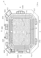
図1〜3は、本発明の競技場の一実施形態であるサッカー場Kを示すもので、サッカー競技が実施される中央部のアリーナ1と、アリーナ1の周部に配置したスタンド構造部2と、アリーナ1の上を開放し、且つ、スタンド構造部2の上を覆う屋根部3とを備えて構成されている。
尚、当該実施形態で説明するサッカー場Kは、主たる構造に鉄骨構造を採用してあり、その平面形状は、南北方向に細長い略矩形形状である。図1においては、紙面右側が北の方位を示している。
1 to 3 show a soccer field K which is an embodiment of a stadium according to the present invention. A
In addition, the soccer field K demonstrated by the said embodiment employ | adopts the steel frame structure as the main structure, The planar shape is a substantially rectangular shape long and thin in the north-south direction. In FIG. 1, the right side of the drawing shows the north direction.
アリーナ1は、北側の辺部1aと南側の辺部1cとが短辺で、東側の辺部1bと西側の辺部1dとが長辺となる矩形平面形状に形成してあり、略全域にわたって天然芝が植え付けてある。
また、アリーナ1は、サッカー場Kの周囲(観客席2Aの外方)Rに略水平状態に広がる地表面Gと略同レベルに形成してある(図2、図3参照)。
The
Further, the
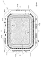
屋根部3は、図2、図3に示すように、屋根板3Aと、屋根板3Aを支持する屋根大梁3Bとを設けて構成してあり、前述のとおり、アリーナ1の上方を除いて、スタンド構造部2の上方全域を覆う状態に設置されている。
即ち、屋根板3Aの前端ラインは、直下の観客席2A(後述)の前端ラインに平面視で略重なるように設定してあり、雨粒が、観客席2Aに垂下するのを防止している。
また、屋根大梁3Bは、スタンド構造部2の柱によって支持されている。
尚、図には示さないが、現実的には、屋根大梁3Bに架設された小梁や桁等を介して屋根板3Aは支持されている。
As shown in FIGS. 2 and 3, the
That is, the front end line of the
The
Although not shown in the drawings, the
スタンド構造部2は、図1に示すように、平面的にも構造的にもアリーナ1の全周にわたって連続するように設けてあり、平面視での外形は、四隅が面取りされた略矩形形状に構成されている。
また、スタンド構造部2は、アリーナ1に面する前端側より後端側ほど高くなる「すり鉢」状に形成された観客席(スタンドに相当)2Aと、その観客席2Aの下方空間に形成されて観客席2Aを下方から支持する複数階層の支持構造部2Bとを備えて構成してある(図2、図3参照)。
当該実施形態のサッカー場Kにおいては、スタンド構造部2の全周の内、西側に配置されているスタンド構造部2がメインスタンド構造部S1として構成され(図2参照)、北側、東側、南側にそれぞれ配置されているスタンド構造部2は、一般スタンド構造部S2として構成されている(図3参照)。
As shown in FIG. 1, the
Further, the
In the soccer field K of this embodiment, the
観客席2Aは、図2、図3に示すように、前端列より後方側に位置する列が徐々に床面が高くなるように多数の段差をつけて形成してあり、それぞれの列の床面上に、多数のベンチbが設置されている。また、観客席2Aには、前記支持構造部2Bの各階層に連通自在な出入口4が適宜箇所に開放状態に設けられている。
As shown in FIGS. 2 and 3, the
支持構造部2Bは、柱、梁、壁、床等を備えた複数階層の構造体として形成してあり、観客席2Aのみならず、屋根部3をも支持する構造として構成されている。
支持構造部2Bには、例えば、駐車場5や、クラブハウス、更衣室、事務室、会議室、倉庫、レストラン、売店、便所等の居室6や、サッカー場Kの周囲Rとアリーナ1とを通風可能な状態に連通させる連通路7や、図には示さないが、階段室や、エレベータ等が設けてある。
The
The
メインスタンド構造部S1は、図1に示すように、支持構造部2Bが、アリーナ1の西側の辺部1dに沿って複数の居室6が連設された居室ゾーンとして構成されており、当該サッカー場Kの主だった設備が設置されている。
メインスタンド構造部S1に形成されている連通路7Aは、隣り合う居室6の間に配置され、サッカー場Kの周囲Rとアリーナ1とにわたって居室ゾーンを貫通する状態に設けられている。
As shown in FIG. 1, the main stand structure portion S1 is configured such that the
The
平面的には、連通路7Aは、アリーナ1の西側の辺部1d方向に間隔をあけた複数個所に設けられている。また、連通路7Aの床は、1階部分の床として構成してあり、サッカー場Kの周囲Rの地表面G、及び、アリーナ1と、略同じレベルとなるように形成されている(図2参照)。
よって、連通路7Aを通したアリーナ1への通風において、空気抵抗をより少なくでき、効率良く通風を図ることができる。尚、この連通路7Aは、アリーナ1に対する通風を叶える手段以外にも使用され、例えば、一般の通路としても利用できるように構成されている。図2中の記号Wは、連通路7Aの側壁を示しており、連通路7Aのアリーナ1側の端部は、上方が解放された構造に形成してある。この解放部分においては、側壁Wの上縁部は、観客席2A側の手摺壁に相当するもので、例えば、上縁部に手摺を設けてあってもよい。
In plan view, the
Therefore, in the ventilation to the
また、メインスタンド構造部S1においては、複数の連通路7Aの設置スペースを確保するに伴って、面積確保が困難となる複数の居室6が生じるが、それらの居室6どうしを、上下に重なる状態に配置することで、観客席2Aのスラブ下の斜めの空間をも有効に利用できるようにし、所定通りの延床面積と居室数を確保している(図2参照)。
Further, in the main stand structure portion S1, a plurality of
一般スタンド構造部S2は、図1に示すように、支持構造部2Bが、主として駐車場5を設けた駐車ゾーンとして構成されている。
一般スタンド構造部S2に形成されている連通路7Bは、図3に示すように、観客席2Aの最前列のスラブと、その下方に位置するアリーナ1とにわたって設けられた垂れ壁8部分に、通風可能な状態に形成した開口部9を備えて構成してある。
従って、サッカー場Kの周囲Rとアリーナ1とは、駐車場5と開口部9を通して通風可能な状態に連通されている。
この開口部9は、アリーナ1の北側の辺部1a、東側の辺部1b、南側の辺部1cそれぞれの長手方向に間隔をあけた複数個所に形成してある(図1参照)。
As shown in FIG. 1, the general stand structure portion S <b> 2 is configured as a parking zone in which the
As shown in FIG. 3, the
Therefore, the periphery R of the soccer field K and the
The
また、スタンド構造部2の内、アリーナ1の四隅に対応した箇所には、アリーナ1の対角線に概ね沿った方向で貫通する連通路7Cが形成してあり、この連通路7Cを通しても、前記連通路7A,7Bと同様にアリーナ1の通気を図ることができる。
Further, a
尚、各連通路7には、図には示さないが、連通路7を開閉操作自在な開閉手段(例えば、扉やシャッター等)が設けてあり、適宜、開閉操作を行って、アリーナ1への通風を切り替えることができるように構成されている。
Although not shown in the drawing, each
当該サッカー場Kによれば、アリーナ1の周りに間隔をあけて配置された複数の連通路7を通して、サッカー場Kの周囲Rと、アリーナ1との充分な通風が可能となり、アリーナ1の全域を対象とした通風環境が得られる。
従って、アリーナ1の全域に植栽されている天然芝の光合成を促進できる好ましい生育環境を整備することができる。
According to the soccer field K, through the plurality of
Therefore, the preferable growth environment which can accelerate | stimulate photosynthesis of the natural turf planted in the whole area of the
また、空間の有効利用によって、連通路7の設置に伴う居室6の延床面積の減少を防止でき、居室ゾーンとしての機能の低下を招かずに、複数の連通路7を確保することが可能となった。
更には、周囲Rの地表面Gに合わせた構造を採用したことで、複雑な根切り工事を実施せずに、短時間に且つ経済的に建設を進めることができるようになった。
Further, by effectively using the space, it is possible to prevent a reduction in the total floor area of the
Furthermore, by adopting a structure that matches the ground surface G of the surrounding R, it has become possible to proceed with construction in a short time and economically without carrying out complicated root cutting work.
また、当該実施形態のサッカー場Kにおいては、図4〜6に示すように、居室6の平面配置として、各居室6を機能別にまとめた平面配置を行うことで、より使い易いものにしている。
Moreover, in the soccer field K of the embodiment, as shown in FIGS. 4 to 6, the planar arrangement of the
図4は、1階平面図を示し、メインスタンド構造部S1には、試合運営に係る居室6をまとめて配置した「試合運営エリアA1」が設けられ、南側の一般スタンド構造部S2には、当該サッカー場Kに係るクラブチームの居室6をまとめて配置した「クラブハウスエリアA2」が設けられている。
尚、試合運営エリアA1の内、一部、連通路7Aと重複する部分A1aに関しては、選手のウォームアップに使用できる空間として構成してあり、連通路7Aの通風を許容できるように構成してある。
FIG. 4 is a plan view of the first floor. The main stand structure section S1 is provided with a “game management area A1” in which the
In addition, a part of the game management area A1 that overlaps with the
図5は、2階平面図を示し、メインスタンド構造部S1には、メディアに係る居室6をまとめて配置した「メディアエリアA3」や、サッカー場Kに従事するスタッフに係る居室6をまとめて配置した「スタッフエリアA4」や、サッカー場Kやサッカーに係る資料の展示や販売等が実施される「ミュージアムエリアA5」が設けられ、南側の一般スタンド構造部S2には、1階と同様に「クラブハウスエリアA2」が設けられている。
FIG. 5 is a plan view of the second floor. In the main stand structure portion S1, the “media area A3” in which the
図6は、3階平面図を示し、3階部分が、外部からサッカー場Kへの出入口階となるように構成してあり、サッカー場Kの全周にわたって周回できる「コンコースエリアA6」が設けてある。この周回路に面して、多数の店舗等の居室6が設けられている。
また、周回路のアリーナ1側の内周部には、車椅子に乗車したまま観戦ができる車椅子席A6aが多数設けられており、サッカー場Kに入場してからの車椅子の移動を最小限にできるように考慮されている。
FIG. 6 is a plan view of the third floor, and the third floor portion is configured to be an entrance / exit floor to the soccer field K from the outside, and a “concourse area A6” that can circulate all around the soccer field K It is provided. Facing this circumferential circuit, there are
In addition, there are many wheelchair seats A6a that can be watched while riding in the wheelchair on the inner periphery of the
また、「その他の居室エリアA7」は、例えば、便所等として使用できる(図5、図6参照)。 Further, the “other living room area A7” can be used as a toilet, for example (see FIGS. 5 and 6).
〔別実施形態〕
以下に他の実施の形態を説明する。
[Another embodiment]
Other embodiments will be described below.
〈1〉 アリーナ1やスタンド2や屋根部3の形状は、適宜変更することが可能である。
従って、競技場K全体としても、平面形状が矩形形状に限るものではなく、正方形形状や、4角形以外の多角形形状であったり、円弧を組み合わせた形状であってもよい。
<1> The shapes of the
Accordingly, the overall stadium K is not limited to a rectangular shape, and may be a square shape, a polygonal shape other than a quadrangular shape, or a shape combining arcs.
〈2〉 連通路7は、先の実施形態で説明した形状や数や仕様に限るものではなく、適宜変更することが可能である。
また、連通路7とアリーナ1とスタンド2Aの外方の地表面Gとが同じレベルに形成してあることに限らず、それら三つの内の何れか二つが同じレベルであったり、それぞれが異なったレベルとして形成してあってもよい。
また、連通路7は、略水平状態に形成してあることに限らず、傾斜状態に形成してあってもよい。
例えば、図7に示すように、地表面Gとそれより低いアリーナ1とにわたって下り勾配の連通路7が設けてあったり、図8に示すように、地表面Gとそれより高いアリーナ1とにわたって上り勾配の連通路7が設けてあってもよい。
<2> The
Further, the
The
For example, as shown in FIG. 7, there is a downwardly communicating
〈3〉 連通路7に、通気を促進する送風装置を備えてあってもよい。その場合、アリーナ1に対する給気側の連通路7と排気側の連通路7とで、送風装置の送風方向を、一連の動線上で揃うように制御することが好ましい。
<3> The
〈4〉 競技場Kの方位や、スタンド構造部2におけるメインスタンド構造部S1の配置、及び、スタンド構造部2における連通路7や居室6や駐車場5の配置は、先の実施形態で説明したものに限るものではなく、適宜、変更が可能である。
<4> The direction of the stadium K, the arrangement of the main stand structure S1 in the
尚、上述のように、図面との対照を便利にするために符号を記したが、該記入により本発明は添付図面の構成に限定されるものではない。また、本発明の要旨を逸脱しない範囲において、種々なる態様で実施し得ることは勿論である。 In addition, as mentioned above, although the code | symbol was written in order to make contrast with drawing convenient, this invention is not limited to the structure of an accompanying drawing by this entry. In addition, it goes without saying that the present invention can be carried out in various modes without departing from the gist of the present invention.
当該発明の競技場Kは、サッカー場に限るものではなく、例えば、陸上競技場やラグビーや野球場等の競技場にも利用できる。 The stadium K of the present invention is not limited to a soccer field, and can be used for an athletic field, a rugby, a baseball field, and other stadiums.
1 アリーナ
2A 観客席(スタンドに相当)
6 居室
7 連通路
G 地表面
1
6
Claims (5)
前記アリーナの周部に配置したスタンドとを備えた競技場であって、
平面視において、前記スタンドの外方と前記アリーナとを通風可能な状態に連通させる複数の連通路を、前記スタンドの下方空間を貫通する状態で、前記アリーナの各辺部に対応させて設けてある競技場。 With the arena,
A stadium comprising a stand arranged around the arena,
In plan view, a plurality of communication passages that communicate with the outside of the stand and the arena so as to allow ventilation are provided corresponding to each side of the arena in a state of passing through the lower space of the stand. A certain stadium.
前記居室ゾーンには、隣り合う前記居室の間に前記連通路が配置してある請求項1に記載の競技場。 In the lower space of the stand, a living room zone in which a plurality of living rooms are continuously provided along the side of the arena is formed,
The stadium according to claim 1, wherein the communication path is arranged between the adjacent rooms in the living room zone.
Priority Applications (1)
| Application Number | Priority Date | Filing Date | Title |
|---|---|---|---|
| JP2014090113A JP6482772B2 (en) | 2014-04-24 | 2014-04-24 | Arena |
Applications Claiming Priority (1)
| Application Number | Priority Date | Filing Date | Title |
|---|---|---|---|
| JP2014090113A JP6482772B2 (en) | 2014-04-24 | 2014-04-24 | Arena |
Publications (2)
| Publication Number | Publication Date |
|---|---|
| JP2015209651A true JP2015209651A (en) | 2015-11-24 |
| JP6482772B2 JP6482772B2 (en) | 2019-03-13 |
Family
ID=54612078
Family Applications (1)
| Application Number | Title | Priority Date | Filing Date |
|---|---|---|---|
| JP2014090113A Active JP6482772B2 (en) | 2014-04-24 | 2014-04-24 | Arena |
Country Status (1)
| Country | Link |
|---|---|
| JP (1) | JP6482772B2 (en) |
Citations (8)
| Publication number | Priority date | Publication date | Assignee | Title |
|---|---|---|---|---|
| JPS6082136U (en) * | 1983-11-14 | 1985-06-07 | 株式会社大氣社 | Large space indoor air flow device |
| JPH07279459A (en) * | 1994-04-14 | 1995-10-27 | Shimizu Corp | Multi-purpose stadium with opening/closing roof and natural turf ground |
| JPH07279457A (en) * | 1994-04-08 | 1995-10-27 | Shimizu Corp | Inspection facilities of soccer stadium |
| JPH0941688A (en) * | 1995-07-27 | 1997-02-10 | Maeda Corp | Multipurpose stadium |
| JPH09310520A (en) * | 1996-05-24 | 1997-12-02 | Ohbayashi Corp | Transferable seat unit and event space in which the seat units are arranged |
| JP2000274100A (en) * | 1999-03-25 | 2000-10-03 | Shimizu Corp | Athletic facility |
| US20120131858A1 (en) * | 2010-11-29 | 2012-05-31 | Qatar Football Association | Revolving roof for an indoor/outdoor stadium |
| JP2012140798A (en) * | 2010-12-29 | 2012-07-26 | Kajima Corp | Stadium with spectator stands |
-
2014
- 2014-04-24 JP JP2014090113A patent/JP6482772B2/en active Active
Patent Citations (8)
| Publication number | Priority date | Publication date | Assignee | Title |
|---|---|---|---|---|
| JPS6082136U (en) * | 1983-11-14 | 1985-06-07 | 株式会社大氣社 | Large space indoor air flow device |
| JPH07279457A (en) * | 1994-04-08 | 1995-10-27 | Shimizu Corp | Inspection facilities of soccer stadium |
| JPH07279459A (en) * | 1994-04-14 | 1995-10-27 | Shimizu Corp | Multi-purpose stadium with opening/closing roof and natural turf ground |
| JPH0941688A (en) * | 1995-07-27 | 1997-02-10 | Maeda Corp | Multipurpose stadium |
| JPH09310520A (en) * | 1996-05-24 | 1997-12-02 | Ohbayashi Corp | Transferable seat unit and event space in which the seat units are arranged |
| JP2000274100A (en) * | 1999-03-25 | 2000-10-03 | Shimizu Corp | Athletic facility |
| US20120131858A1 (en) * | 2010-11-29 | 2012-05-31 | Qatar Football Association | Revolving roof for an indoor/outdoor stadium |
| JP2012140798A (en) * | 2010-12-29 | 2012-07-26 | Kajima Corp | Stadium with spectator stands |
Also Published As
| Publication number | Publication date |
|---|---|
| JP6482772B2 (en) | 2019-03-13 |
Similar Documents
| Publication | Publication Date | Title |
|---|---|---|
| JP2021502504A (en) | House building structure | |
| KR20180132870A (en) | Urban Forest High-rise Villa | |
| KR101479400B1 (en) | Multipurpose greenhouse dome | |
| US5775043A (en) | Underground construction | |
| JP5248101B2 (en) | Buildings that consider the natural environment | |
| Latipovich | PLANNING DECISION OF LANDSCAPE OBJECTS AND LAF ON EXPLOITED ROOFS | |
| JP6482772B2 (en) | Arena | |
| JP6315252B2 (en) | Green bench | |
| JP5139052B2 (en) | Watering curtain forming device | |
| WO2009127762A1 (en) | System for creating landscaped areas on walls | |
| JP6581326B1 (en) | pergola | |
| JP2020066932A (en) | Natural lawn facility | |
| JP2017133338A (en) | Roof deck gardening plate, roof deck plate, and moveable garden system | |
| JP5032824B2 (en) | Decorative planting equipment | |
| JP2015209650A (en) | Stadium | |
| KR100725244B1 (en) | Indoor horse riding field | |
| EP2877645B1 (en) | Structure to achieve green areas on building roofs | |
| CN203724731U (en) | Multifunctional stereo encircled golf driving range | |
| KR102256650B1 (en) | Basic block assembly for vinyl house and basic construction method of vinyl house using same | |
| JP5032375B2 (en) | Building greening equipment | |
| KR200409809Y1 (en) | Indoor horse riding field | |
| JP2019135976A (en) | Greening structure body and greening structure using the same | |
| JP2004003222A (en) | Reinforced concrete building | |
| JP2000336966A (en) | Planting type drive-in multistory parking space | |
| JPH0530850A (en) | Method and structure for producing and growing natural lawn bed |
Legal Events
| Date | Code | Title | Description |
|---|---|---|---|
| A621 | Written request for application examination |
Free format text: JAPANESE INTERMEDIATE CODE: A621 Effective date: 20170328 |
|
| A977 | Report on retrieval |
Free format text: JAPANESE INTERMEDIATE CODE: A971007 Effective date: 20180111 |
|
| A131 | Notification of reasons for refusal |
Free format text: JAPANESE INTERMEDIATE CODE: A131 Effective date: 20180123 |
|
| A521 | Request for written amendment filed |
Free format text: JAPANESE INTERMEDIATE CODE: A523 Effective date: 20180323 |
|
| A131 | Notification of reasons for refusal |
Free format text: JAPANESE INTERMEDIATE CODE: A131 Effective date: 20180724 |
|
| A521 | Request for written amendment filed |
Free format text: JAPANESE INTERMEDIATE CODE: A523 Effective date: 20180912 |
|
| TRDD | Decision of grant or rejection written | ||
| A01 | Written decision to grant a patent or to grant a registration (utility model) |
Free format text: JAPANESE INTERMEDIATE CODE: A01 Effective date: 20190205 |
|
| A61 | First payment of annual fees (during grant procedure) |
Free format text: JAPANESE INTERMEDIATE CODE: A61 Effective date: 20190213 |
|
| R150 | Certificate of patent or registration of utility model |
Ref document number: 6482772 Country of ref document: JP Free format text: JAPANESE INTERMEDIATE CODE: R150 |