JP2015206423A - cam mechanism - Google Patents
cam mechanism Download PDFInfo
- Publication number
- JP2015206423A JP2015206423A JP2014087824A JP2014087824A JP2015206423A JP 2015206423 A JP2015206423 A JP 2015206423A JP 2014087824 A JP2014087824 A JP 2014087824A JP 2014087824 A JP2014087824 A JP 2014087824A JP 2015206423 A JP2015206423 A JP 2015206423A
- Authority
- JP
- Japan
- Prior art keywords
- cam
- region
- ball
- cam member
- cam groove
- Prior art date
- Legal status (The legal status is an assumption and is not a legal conclusion. Google has not performed a legal analysis and makes no representation as to the accuracy of the status listed.)
- Pending
Links
- 230000007246 mechanism Effects 0.000 title claims abstract description 47
- 238000005096 rolling process Methods 0.000 claims abstract description 50
- 230000005540 biological transmission Effects 0.000 claims description 18
- 230000003247 decreasing effect Effects 0.000 claims description 2
- 238000006073 displacement reaction Methods 0.000 abstract 1
- 230000002093 peripheral effect Effects 0.000 description 11
- 230000007423 decrease Effects 0.000 description 10
- 239000002783 friction material Substances 0.000 description 8
- 230000004323 axial length Effects 0.000 description 3
- 230000010363 phase shift Effects 0.000 description 3
- 230000004044 response Effects 0.000 description 2
- 230000004043 responsiveness Effects 0.000 description 2
- 238000013459 approach Methods 0.000 description 1
- 230000000903 blocking effect Effects 0.000 description 1
- 230000008859 change Effects 0.000 description 1
- 230000006835 compression Effects 0.000 description 1
- 238000007906 compression Methods 0.000 description 1
- 230000000694 effects Effects 0.000 description 1
- 230000007704 transition Effects 0.000 description 1
Images


Classifications
-
- F—MECHANICAL ENGINEERING; LIGHTING; HEATING; WEAPONS; BLASTING
- F16—ENGINEERING ELEMENTS AND UNITS; GENERAL MEASURES FOR PRODUCING AND MAINTAINING EFFECTIVE FUNCTIONING OF MACHINES OR INSTALLATIONS; THERMAL INSULATION IN GENERAL
- F16D—COUPLINGS FOR TRANSMITTING ROTATION; CLUTCHES; BRAKES
- F16D23/00—Details of mechanically-actuated clutches not specific for one distinct type
- F16D23/12—Mechanical clutch-actuating mechanisms arranged outside the clutch as such
-
- F—MECHANICAL ENGINEERING; LIGHTING; HEATING; WEAPONS; BLASTING
- F16—ENGINEERING ELEMENTS AND UNITS; GENERAL MEASURES FOR PRODUCING AND MAINTAINING EFFECTIVE FUNCTIONING OF MACHINES OR INSTALLATIONS; THERMAL INSULATION IN GENERAL
- F16D—COUPLINGS FOR TRANSMITTING ROTATION; CLUTCHES; BRAKES
- F16D25/00—Fluid-actuated clutches
- F16D25/06—Fluid-actuated clutches in which the fluid actuates a piston incorporated in, i.e. rotating with the clutch
- F16D25/062—Fluid-actuated clutches in which the fluid actuates a piston incorporated in, i.e. rotating with the clutch the clutch having friction surfaces
-
- F—MECHANICAL ENGINEERING; LIGHTING; HEATING; WEAPONS; BLASTING
- F16—ENGINEERING ELEMENTS AND UNITS; GENERAL MEASURES FOR PRODUCING AND MAINTAINING EFFECTIVE FUNCTIONING OF MACHINES OR INSTALLATIONS; THERMAL INSULATION IN GENERAL
- F16D—COUPLINGS FOR TRANSMITTING ROTATION; CLUTCHES; BRAKES
- F16D13/00—Friction clutches
- F16D13/22—Friction clutches with axially-movable clutching members
- F16D13/38—Friction clutches with axially-movable clutching members with flat clutching surfaces, e.g. discs
- F16D13/52—Clutches with multiple lamellae ; Clutches in which three or more axially moveable members are fixed alternately to the shafts to be coupled and are pressed from one side towards an axially-located member
-
- F—MECHANICAL ENGINEERING; LIGHTING; HEATING; WEAPONS; BLASTING
- F16—ENGINEERING ELEMENTS AND UNITS; GENERAL MEASURES FOR PRODUCING AND MAINTAINING EFFECTIVE FUNCTIONING OF MACHINES OR INSTALLATIONS; THERMAL INSULATION IN GENERAL
- F16D—COUPLINGS FOR TRANSMITTING ROTATION; CLUTCHES; BRAKES
- F16D23/00—Details of mechanically-actuated clutches not specific for one distinct type
- F16D23/12—Mechanical clutch-actuating mechanisms arranged outside the clutch as such
- F16D2023/123—Clutch actuation by cams, ramps or ball-screw mechanisms
-
- F—MECHANICAL ENGINEERING; LIGHTING; HEATING; WEAPONS; BLASTING
- F16—ENGINEERING ELEMENTS AND UNITS; GENERAL MEASURES FOR PRODUCING AND MAINTAINING EFFECTIVE FUNCTIONING OF MACHINES OR INSTALLATIONS; THERMAL INSULATION IN GENERAL
- F16D—COUPLINGS FOR TRANSMITTING ROTATION; CLUTCHES; BRAKES
- F16D2121/00—Type of actuator operation force
- F16D2121/14—Mechanical
-
- F—MECHANICAL ENGINEERING; LIGHTING; HEATING; WEAPONS; BLASTING
- F16—ENGINEERING ELEMENTS AND UNITS; GENERAL MEASURES FOR PRODUCING AND MAINTAINING EFFECTIVE FUNCTIONING OF MACHINES OR INSTALLATIONS; THERMAL INSULATION IN GENERAL
- F16D—COUPLINGS FOR TRANSMITTING ROTATION; CLUTCHES; BRAKES
- F16D2125/00—Components of actuators
- F16D2125/02—Fluid-pressure mechanisms
Landscapes
- Engineering & Computer Science (AREA)
- General Engineering & Computer Science (AREA)
- Mechanical Engineering (AREA)
- Mechanical Operated Clutches (AREA)
- Transmission Devices (AREA)
- Hydraulic Clutches, Magnetic Clutches, Fluid Clutches, And Fluid Joints (AREA)
- One-Way And Automatic Clutches, And Combinations Of Different Clutches (AREA)
Abstract
Description
この発明は、二つの部材が対向する面にカム溝を形成し、そのカム溝に転動体を収容するとともに、その転動体を二つの部材により挟み付けるように構成されたカム機構に関するものである。 The present invention relates to a cam mechanism configured to form a cam groove on a surface where two members face each other, accommodate a rolling element in the cam groove, and sandwich the rolling element between the two members. .
特許文献1,2,3には、摩擦力によりトルクを伝達する多板クラッチを押圧して伝達トルク容量を増大させるように構成されたボールカム機構が記載されている。特許文献1に記載されたボールカム機構は、トルクを推力に変えて伝達するものであり、ボールカム機構の出力部材であるピストンが、多板クラッチの摩擦材を押圧するように構成されている。また、特許文献1に記載されたボールカム機構は、多板クラッチを解放させているときに、摩擦材とピストンとの間に介在するオイルの粘性抵抗が作用することを抑制するために、多板クラッチが解放されているときにおける摩擦材とピストンとの隙間が大きくなるように配置されている。
一方、多板クラッチが解放されているときにおける摩擦材とピストンとの隙間を大きくすると、多板クラッチを係合させるために入力部材を回転させ始めてから、ピストンと摩擦材とが接触し始めるまでの時間が長くなり応答性が低下する可能性がある。そのため、特許文献1に記載されたボールカム機構のカム溝には、多板クラッチが解放しているときにボールを収容する半円状の凹部と、摩擦材とピストンとが接触するときにボールが転がり接触する傾斜部とが形成され、その境界部分が段差になっている。したがって、入力部材が回転し始めると、ボールが段差を乗り越えて傾斜部を転がり接触するので、入力部材の回転量に対する出力部材の移動量の割合が大きくなり、ピストンと摩擦材とが接触するまでの時間を短縮することができる。また、ボールの位相がずれることを抑制するために、特許文献1に記載されたボールカム機構は、複数のボールを保持する保持器を備えている。 On the other hand, if the clearance between the friction material and the piston is increased when the multi-plate clutch is released, the input member starts rotating to engage the multi-plate clutch until the piston and the friction material start to contact each other. There is a possibility that the response time will be lowered due to the length of time. For this reason, the cam groove of the ball cam mechanism described in Patent Document 1 has a semicircular recess that accommodates the ball when the multi-plate clutch is released, and the ball when the friction material and the piston come into contact with each other. An inclined portion that makes rolling contact is formed, and the boundary portion is a step. Therefore, when the input member starts to rotate, the ball moves over the step and makes contact with the inclined portion, so that the ratio of the amount of movement of the output member to the amount of rotation of the input member increases and the piston and the friction material contact each other. Can be shortened. In order to prevent the balls from shifting in phase, the ball cam mechanism described in Patent Document 1 includes a cage that holds a plurality of balls.
なお、特許文献2に記載されたボールカム機構は、円周方向の両側に向かうにつれて徐々にカム溝が浅くなるように形成されている。また、特許文献3に記載されたボールカム機構は、カム溝のうち推力を生じさせる領域の底面の傾斜角度を一定に形成している。
Note that the ball cam mechanism described in
ところで、二つの部材がそれぞれ対向する面に円周方向に所定の間隔を空けて複数のカム溝を形成し、それら各カム溝に一つずつ収容された転動体を上記二つの部材により挟み付けるように構成されたカム機構では、転動体を挟み付ける荷重が小さいと、いずれかの転動体の位相が他の転動体の位相からずれてしまう可能性がある。そのため、転動体の位相がずれることを抑制するために、特許文献1に記載されたように転動体を保持する保持器を設けると、部品点数が増加し、またはカム機構の軸長が増大し、あるいは転動体と保持器との摩擦による動力損失が増大する可能性がある。 By the way, a plurality of cam grooves are formed at predetermined intervals in the circumferential direction on the surfaces where the two members face each other, and the rolling elements housed in the respective cam grooves are sandwiched between the two members. In the cam mechanism configured as described above, if the load sandwiching the rolling elements is small, the phase of one of the rolling elements may be shifted from the phase of the other rolling element. Therefore, in order to prevent the rolling element from being out of phase, providing a cage for holding the rolling element as described in Patent Document 1 increases the number of parts or increases the axial length of the cam mechanism. Alternatively, there is a possibility that power loss due to friction between the rolling element and the cage increases.
そこで、カム溝の底面の傾斜角度が次第に大きくなるように形成することにより、転動体の位相がずれることを抑制することができる。しかしながら、カム溝の底面の傾斜角度が次第に大きくなるように形成すると、そのカム溝に沿って軸線方向に摺動する出力側の部材の推力が次第に小さくなる。したがって、摩擦力によりトルクを伝達する摩擦係合装置を、出力側の部材が押圧してその摩擦係合装置の伝達トルク容量を増大させるように、カム機構が設けられている場合には、出力側の部材が摩擦係合装置に接触した後に、大きな推力が要求される。そのため、上記のように転動体の位相がずれることを抑制するためにカム溝の底面の傾斜角度が次第に大きくなるように形成すると、摩擦係合装置を押圧するための十分な推力を出力することができない可能性がある。 Thus, by forming the cam groove so that the inclination angle of the bottom surface gradually increases, it is possible to suppress the phase of the rolling element from shifting. However, if the inclination angle of the bottom surface of the cam groove is gradually increased, the thrust of the output member that slides in the axial direction along the cam groove gradually decreases. Therefore, when the cam mechanism is provided so that the output side member presses the friction engagement device that transmits torque by the frictional force and increases the transmission torque capacity of the friction engagement device, A large thrust is required after the side member contacts the friction engagement device. For this reason, if the inclination angle of the bottom surface of the cam groove is gradually increased in order to prevent the rolling element from shifting in phase as described above, sufficient thrust for pressing the friction engagement device is output. May not be possible.
この発明は上述した事情を背景としてなされたものであって、転動体の位相がずれることを抑制しつつ、大きな推力を出力することができるカム機構を提供することを目的とするものである。 The present invention has been made against the background described above, and it is an object of the present invention to provide a cam mechanism that can output a large thrust while suppressing the phase of rolling elements from shifting.
上記の目的を達成するために、請求項1の発明は、軸線方向で互いに対向しかつ相対回転する第1カム部材と第2カム部材とを有し、前記第1カム部材における前記第2カム部材に対向した対向面に軸線方向に窪みかつ窪み深さが最も深い箇所から前記各カム部材の回転方向での一方の回転方向に向けて次第に浅くなる第1カム溝が形成され、前記第2カム部材における前記第1カム部材に対向した対向面に軸線方向に窪みかつ深さが最も深い箇所から前記各カム部材の回転方向での他方の回転方向に向けて次第に浅くなるように前記第1カム溝と対称形状の第2カム溝が形成され、前記各カム溝の間に転動体が挟み込まれ、前記第1カム部材と前記第2カム部材とが相対回転することにより一方のカム部材が軸線方向に移動するように構成されるとともに、摩擦力によりトルクを伝達する摩擦係合装置に対して前記一方のカム部材における前記対向面とは反対側の端面が軸線方向で所定の間隔を空けて配置され、前記各カム部材の位相差が所定量以上のときに、前記一方のカム部材が前記摩擦係合装置を押圧することにより該摩擦係合装置の伝達トルク容量を増大させるカム機構において、前記各カム溝は、前記位相差が所定量以下のときに前記転動体が転がり接触する前記各カム溝の底面における前記各カム部材の回転面に対する傾斜角度が、前記位相差が大きくなるにつれて大きくなるように形成された第1領域と、前記位相差が所定量以上のときに前記転動体が転がり接触する前記各カム溝の底面の前記回転面に対する傾斜角度が、前記第1領域における最も大きい傾斜角度よりも小さく形成された第2領域とを備えていることを特徴とするものである。 In order to achieve the above object, the invention of claim 1 includes a first cam member and a second cam member which are opposed to each other in the axial direction and relatively rotate, and the second cam in the first cam member. A first cam groove is formed in the opposing surface facing the member, the first cam groove gradually becoming shallower in a rotational direction of each cam member from a portion that is recessed in the axial direction and has the deepest recess depth. In the cam member, the first surface is formed so as to gradually become shallower from a portion that is recessed in the axial direction on the opposite surface of the cam member facing the first cam member and has the deepest depth toward the other rotation direction in the rotation direction of each cam member. A second cam groove that is symmetrical with the cam groove is formed, a rolling element is sandwiched between the cam grooves, and the first cam member and the second cam member are rotated relative to each other, whereby one cam member is Configured to move in the axial direction In addition, an end surface of the one cam member opposite to the facing surface is disposed at a predetermined interval in the axial direction with respect to the friction engagement device that transmits torque by a frictional force. In the cam mechanism in which the one cam member presses the friction engagement device to increase the transmission torque capacity of the friction engagement device when the phase difference is equal to or larger than a predetermined amount, each cam groove is A first angle formed so that an inclination angle of the bottom surface of each cam groove with which the rolling element is in rolling contact with the rotation surface of each cam member when the phase difference is equal to or less than a predetermined amount increases as the phase difference increases. An inclination angle of the bottom surface of each cam groove with which the rolling element is in rolling contact with the region when the phase difference is equal to or larger than a predetermined amount is the largest inclination angle in the first region And it is characterized in that it comprises a second region that is smaller than.
請求項2の発明は、請求項1の発明において、前記第1領域と前記第2領域とは、前記各カム部材の円周方向に連なって形成され、前記第1領域と前記第2領域との境界部分で前記転動体が前記カム溝の底面に接触する際に、前記一方のカム部材と前記摩擦係合装置とが接触し始めるように形成されていることを特徴とするカム機構である。 According to a second aspect of the present invention, in the first aspect of the invention, the first region and the second region are formed continuously in a circumferential direction of each cam member, and the first region, the second region, When the rolling element contacts the bottom surface of the cam groove at the boundary portion, the cam mechanism is formed so that the one cam member and the friction engagement device start to contact each other. .
請求項3の発明は、請求項1または2の発明において、前記第2領域は、前記傾斜角度が一定に形成されていることを特徴とするカム機構である。 A third aspect of the present invention is the cam mechanism according to the first or second aspect of the present invention, wherein the second region is formed with a constant inclination angle.
請求項4の発明は、請求項1または2の発明において、前記位相差が大きくなるにつれて前記一方のカム部材が軸線方向に押圧される荷重が大きくなるように、前記第2領域における前記傾斜角度が回転方向に向けて次第に小さく形成されていることを特徴とするカム機構である。 According to a fourth aspect of the present invention, in the first or second aspect of the present invention, the inclination angle in the second region is set such that a load applied to the one cam member in the axial direction increases as the phase difference increases. The cam mechanism is characterized in that is gradually formed smaller in the rotational direction.
この発明によれば、各カム部材が対向する面に複数のカム溝が形成され、そのカム溝に転動体が収容されるとともに、その収容された転動体が各カム部材に挟まれている。また、各カム部材の位相差が所定量以上のときに、軸線方向に所定の間隔を空けて配置された摩擦係合装置を一方のカム部材が押圧してその摩擦係合装置の伝達トルク容量を増大させる。そして、カム溝は、各カム部材の位相差が所定量以下のときに転動体が転がり接触するカム溝の底面の回転面に対する傾斜角度が、位相差が大きくなるにつれて大きくなるように形成された第1領域を備えている。そのため、摩擦係合装置をカム部材が押圧することにより生じる摩擦係合装置からの大きな反力を受けるまでの間であっても、転動体の位相がずれる方向に対向した荷重をカム溝から転動体に作用させ、転動体の位相がずれることを抑制することができる。その結果、転動体の位相を調整するための保持器などを設ける必要がないので、部品数を低減することやカム機構の軸長を短縮することができる。また、保持器と転動体との摩擦抵抗が生じることがないので、カム機構の荷重の伝達効率を向上させることができる。さらに、転動体とカム溝の底面とが滑ることによる摩擦抵抗を減少させることができるので、カム機構に入力されるトルクまたはカム機構でトルクを生じさせるために入力される動力を低減することができる。 According to the present invention, a plurality of cam grooves are formed on the surfaces facing each cam member, and the rolling elements are accommodated in the cam grooves, and the accommodated rolling elements are sandwiched between the cam members. In addition, when the phase difference between the cam members is equal to or greater than a predetermined amount, one cam member presses the friction engagement device arranged at a predetermined interval in the axial direction and the transmission torque capacity of the friction engagement device Increase. The cam groove is formed such that when the phase difference of each cam member is equal to or less than a predetermined amount, the inclination angle of the bottom surface of the cam groove with which the rolling element is in rolling contact with the rotation surface increases as the phase difference increases. A first region is provided. For this reason, even when a large reaction force from the frictional engagement device generated by the cam member pressing the frictional engagement device is received, the load facing the direction in which the rolling elements are out of phase is transferred from the cam groove. It can be made to act on a moving body and it can control that a phase of a rolling element shifts. As a result, there is no need to provide a cage or the like for adjusting the phase of the rolling elements, so that the number of parts can be reduced and the shaft length of the cam mechanism can be shortened. In addition, since frictional resistance between the cage and the rolling element does not occur, the load transmission efficiency of the cam mechanism can be improved. Furthermore, since the frictional resistance caused by sliding between the rolling element and the bottom surface of the cam groove can be reduced, the torque input to the cam mechanism or the power input to generate the torque by the cam mechanism can be reduced. it can.
また、カム溝は、各カム部材の位相差が所定量以上のときに転動体が転がり接触するカム溝の底面の回転面に対する傾斜角度が、第1領域における最も大きい傾斜角度よりも小さく形成された第2領域を更に備えているので、その第2領域で転動体がカム溝の底面に接触しているときには、カム機構から出力される推力を大きくすることができる。その結果、摩擦係合装置を押圧するための十分な推力を出力することができる。 In addition, the cam groove is formed such that an inclination angle of the bottom surface of the cam groove with which the rolling element comes into rolling contact with the rotation surface when the phase difference of each cam member is a predetermined amount or more is smaller than the largest inclination angle in the first region. Since the second region is further provided, the thrust output from the cam mechanism can be increased when the rolling element is in contact with the bottom surface of the cam groove in the second region. As a result, a sufficient thrust for pressing the friction engagement device can be output.
さらに、第1領域と第2領域とを形成することにより、カム溝の底面の全域の傾斜角度を小さく形成したものよりも、カム溝の長さを短くすることができる。そのため、形成するカム溝の数を多くすれば、カム溝に収容される転動体に作用する面圧を低減することができる。その結果、転動体の剛性を低減すること、すなわち転動体を小型化することができるので、カム機構の軸長を短くすることができる。または、カム溝の長さを短くすることができるので、カム溝が形成される位置を内側にすることができる。その結果、カム溝に収容される転動体に作用する遠心力を低減することができるので、転動体が外側に離脱することを抑制することができる。さらにまた、カム溝の長さを短くすることにより、各カム部材の位相の変化量に対する出力側の部材の移動量を大きくすることができる。そのため、カム機構の応答性を向上させることができる。 Further, by forming the first region and the second region, the length of the cam groove can be made shorter than that in which the inclination angle of the entire bottom surface of the cam groove is made smaller. Therefore, if the number of cam grooves to be formed is increased, the surface pressure acting on the rolling elements accommodated in the cam grooves can be reduced. As a result, the rigidity of the rolling element can be reduced, that is, the rolling element can be reduced in size, so that the axial length of the cam mechanism can be shortened. Or since the length of a cam groove can be shortened, the position where a cam groove is formed can be made inside. As a result, since the centrifugal force acting on the rolling elements accommodated in the cam grooves can be reduced, it is possible to suppress the rolling elements from separating outward. Furthermore, by reducing the length of the cam groove, the amount of movement of the output side member with respect to the amount of change in the phase of each cam member can be increased. Therefore, the responsiveness of the cam mechanism can be improved.
さらに、第2領域における傾斜角度を一定に形成する場合には、第2領域におけるカム溝の底面の加工精度が低下することを抑制することができるので、出力される荷重がばらつくなどの性能の低下を抑制することができる。 Further, when the inclination angle in the second region is formed constant, it is possible to suppress a decrease in the processing accuracy of the bottom surface of the cam groove in the second region, so that the output load varies. The decrease can be suppressed.
一方、各カム部材の位相差が大きくなるにつれて一方のカム部材が軸線方向に押圧される荷重が大きくなるように、第2領域における傾斜角度を回転方向に向けて次第に小さく形成することにより、転動体が第1領域におけるカム溝の底面を転がって第2領域におけるカム溝の底面に移動する際に、出力側の部材が急激に軸線方向に移動することを抑制することができる。 On the other hand, as the phase difference of each cam member increases, the inclination angle in the second region is gradually decreased toward the rotation direction so that the load applied to the one cam member in the axial direction is increased, thereby reducing the rotation. When the moving body rolls on the bottom surface of the cam groove in the first region and moves to the bottom surface of the cam groove in the second region, the output side member can be prevented from moving suddenly in the axial direction.
この発明に係るカム機構は、摩擦力によりトルクを伝達するように構成された従来知られているクラッチやブレーキなどの摩擦係合装置を押圧することにより、その摩擦係合装置の伝達トルク容量を増大させる推力発生機構として使用することができる。 The cam mechanism according to the present invention presses a conventionally known friction engagement device such as a clutch or a brake configured to transmit torque by frictional force, thereby reducing the transmission torque capacity of the friction engagement device. It can be used as a thrust generating mechanism for increasing.
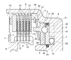
図7には、複数のプレートを軸線方向に交互に配置して形成された従来知られている多板クラッチ1に、ボールカム機構2が推力を付与することにより、多板クラッチ1の伝達トルク容量を増大させるように構成された例を示している。この多板クラッチ1およびボールカム機構2は、変速機などのハウジング3の内部に設けられている。具体的には、第1円筒部4と、第1円筒部4の一方側の開口部から外側に形成されたフランジ部5と、フランジ部5の外周部に一方の端部が連結された第2円筒部6と、第1円筒部4の他方側の開口部を閉じる底面部7と、第1円筒部4よりも内側に所定の間隔を空け、かつ一方の端部が底面部7に連結された円筒状の突出部8とによりハウジング3が形成され、その第1円筒部4と突出部8との間の空間に、ボールカム機構2が設けられ、第2円筒部6の内側に多板クラッチ1が設けられている。
FIG. 7 shows the transmission torque capacity of the multi-plate clutch 1 by applying a thrust force to the conventionally known multi-plate clutch 1 formed by alternately arranging a plurality of plates in the axial direction. Shows an example configured to increase. The multi-plate clutch 1 and the
ここで、図7に示す多板クラッチ1の構成を簡単に説明する。図7に示す多板クラッチ1は、図示しない入力軸に連結された環状の第1回転部材9および図示しない出力軸に連結された環状の第2回転部材10がトルクを伝達する状態と、トルクの伝達を遮断した状態とを選択的に切り替えるものである。具体的には、第1回転部材8の側面には、ハウジング3の底面部7側に向けて軸線方向に突出した円筒状の第1クラッチドラム11が形成され、その第1クラッチドラム11の外側には、環状に形成された複数のドライブプレート12が一体に回転するように嵌合されている。このドライブプレート12は、後述するドリブンプレート13と接触することによりトルクを伝達するものであり、ドライブプレート12とドリブンプレート13とが交互に配置される。したがって、ドライブプレート12同士は、ドリブンプレート13が挟まれる程度の隙間を空けて互いに所定の間隔を空けて配置されている。
Here, the configuration of the multi-plate clutch 1 shown in FIG. 7 will be briefly described. The multi-plate clutch 1 shown in FIG. 7 includes a state in which torque is transmitted between an annular first rotating member 9 connected to an input shaft (not shown) and an annular second rotating
一方、第2回転部材10の側面には、ハウジング3の底面部7側に軸線方向に突出するとともに、ドライブプレート12の外径よりも内径が大きい円筒状の第2クラッチドラム14が形成されている。その第2クラッチドラム14の内側には、環状に形成された複数のドリブンプレート13が、ドライブプレート12と交互に配置され、かつ第2クラッチドラム14と一体に回転するように嵌合されている。なお、ドライブプレート12とドリブンプレート13とのいずれか一方のプレートの両側面には、摩擦材15が一体に形成されている。
On the other hand, a cylindrical second
したがって、図7に示す多板クラッチ1は、ドライブプレート12とドリブンプレート13とを接触させるように軸線方向に押圧されることにより、ドライブプレート12とドリブンプレート13とが押圧される荷重と摩擦係数とに応じたトルクを伝達することができる。すなわち、ドライブプレート12とドリブンプレート13とが接触する荷重を制御することにより、多板クラッチ1の伝達トルク容量が制御される。具体的には、ドライブプレート12とドリブンプレート13とが押圧される荷重を増大させることにより、多板クラッチ1の伝達トルク容量が増大させられる。
Therefore, the multi-plate clutch 1 shown in FIG. 7 is pressed in the axial direction so that the
そのため、図7に示す例では、多板クラッチ1を押圧する荷重を制御するようにボールカム機構2が設けられている。すなわち、多板クラッチ1に要求される伝達トルク容量に応じて多板クラッチ1を押圧する荷重を制御し、多板クラッチ1がトルクの伝達を遮断するときには、多板クラッチ1から離隔して、多板クラッチ1を押圧する荷重を「0」にするようにボールカム機構2が構成されている。
Therefore, in the example shown in FIG. 7, the
図7に示すボールカム機構2は、入力部材16のトルクを軸線方向の推力に変換して出力部材18から出力するように構成されており、入力部材16における出力部材18に対向した面には、軸線方向に窪んだ複数のカム溝19が、円周方向に所定の間隔を空けて形成され、出力部材18における入力部材16に対向した面にも同様に、軸線方向に窪んだ複数のカム溝20が、円周方向に所定の間隔を空けて形成され、それらのカム溝19,20の底面にボール17が転がり接触するように構成されている。具体的には、カム溝19,20の間にボール17を収容した状態で、入力部材16と出力部材18とがボール17を挟み付けるように取り付けられている。なお、ここに示す例では、ボール17を使用したボールカム機構を例に挙げて説明しているが、カム溝と転がり接触するように構成されていればよく、ローラなどの他の部材であってもよい。また、出力部材18が傾くことを抑制するために、円周方向に所定の間隔を空けて三つ以上のカム溝19を形成するとともに、カム溝19と同様に円周方向に所定の間隔を空けてカム溝19と同数のカム溝20を形成し、それらカム溝19,20のそれぞれにボール17を設けることが好ましい。
The
図7に示す入力部材16は、環状に形成されており、ハウジング3の突出部8の外側、かつ第1円筒部4の内側に嵌め込まれている。この入力部材16は、図示しない油圧源から供給される油圧に応じてトルクを発生させるアクチュエータとして機能するように構成されている。具体的には、ハウジング3の底面部7における外周側には、円周方向に所定の間隔を空けて複数の壁部21が軸線方向に突出して形成され、かつ入力部材16における底面部7側の端面には、壁部21同士の間に挿入される複数の突起部22が形成されている。すなわち、壁部21と突起部22とは、軸線方向で重なる位置に形成され、円周方向で交互に配置されている。したがって、壁部21と突起部22との間にオイルが供給されることにより、突起部22が円周方向に押圧されてトルクが生じる。また、入力部材16はハウジング3と相対回転するように突出部8に嵌合させられるので、入力部材16の端面とハウジング3の底面部7との間には、スラストベアリング23が設けられている。さらに、壁部21と突起部22との間に供給されるオイルが漏洩することを抑制するために、入力部材16の内周面および外周面には、それぞれOリングなどのシール部材24,25が設けられている。なお、図7に示す例では、入力部材16がアクチュエータとして機能するように構成されているが、図示しないモータなどにより入力部材16にトルクを伝達するように構成されていてもよい。
The
一方、出力部材18は、入力部材16から軸線方向の押圧力を受けて移動するものであり、図7に示す例では、軸線方向に移動することができ、かつ回転不能にハウジング3に取り付けられている。具体的には、出力部材18は、環状に形成されており、その外周面と第1円筒部4の内周面とがスプラインなどにより係合させられている。なお、出力部材18の内周面は、突出部8に嵌合させられている。また、出力部材18は、ドライブプレート12またはドリブンプレート13を押圧するように構成されており、出力部材18におけるカム溝20が形成された面とは反対側の端面には、ドライブプレート12とドリブンプレート13とが半径方向で重なっている位置を押圧する円筒状の押圧部26が形成されている。
On the other hand, the
上述したようにボール17が入力部材16と出力部材18とに形成されたカム溝19,20に収容されている。また、多板クラッチ1がトルクの伝達を遮断しているときには、出力部材18がドリブンプレート13から離隔し、かつ突起部22と壁部21との間に油圧が供給されない。そのため、出力部材18が入力部材16から離隔してしまうと、ボール17がカム溝19,20から離脱してしまうので、図7に示す例では、出力部材18を常時、入力部材16側に押圧するリターンスプリング27が設けられている。なお、図7に示す例では、リターンスプリング27として皿バネを設けているが、圧縮バネなどの他の弾性部材を配置していてもよい。また、図7に示す例では、リターンスプリング27の外周部分の位置決めをするためにスナップリング28が設けられている。
As described above, the
上述したように図7に示すボールカム機構2は、入力部材16のトルクがボール17を介して出力部材18を軸線方向に押圧する荷重として伝達される。したがって、出力部材18がドリブンプレート13に接触するまでの間は、出力部材18が入力部材16から押圧される荷重に対抗した反力は、リターンスプリング27のばね荷重のみとなる。このリターンスプリング27は、上述したようにボール17がカム溝19,20から離脱することを抑制するように作用させるためのものであり、比較的小さな荷重に設定されている。また、図7に示す例では、円周方向に複数のボール17が設けられており、そのカム溝19,20やボール17には、加工精度などに基づく不可避的な個体差がある。したがって、出力部材18がドリブンプレート13に接触するまでの間は、ボール17を挟み付ける荷重が小さいので、いずれか一つのボール17がカム溝19,20を滑って、他のボール17との位相がずれてしまう可能性がある。そのため、図7に示すカム溝19,20は、ボール17が円周方向に滑ってしまうことを抑制することができるように構成されている。
As described above, in the
一方、出力部材18がドリブンプレート13に接触しているときには、リターンスプリング27のばね荷重に加えてドリブンプレート13の剛性などに応じた反力が作用するので、上述したようにボール17がカム溝19,20から離脱しにくいが、出力部材18がドリブンプレート13を押圧するために要求される荷重が大きい。そのため、図7に示すカム溝19,20は、出力部材18がドリブンプレート13に接触するときに、出力部材18が入力部材16から押圧される荷重が大きくなるように、言い換えると、入力部材16のトルクに対して出力部材18が押圧される荷重が大きくなるように構成されている。
On the other hand, when the
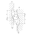
そのカム溝19,20の形状の一例について図1を参照して説明する。なお、入力部材16に形成されたカム溝19は、入力部材16の回転方向での一方の回転方向に向けて次第にカム溝19の深さが浅くなるように形成され、出力部材18に形成されたカム溝20は、入力部材16の回転方向での他方の回転方向に向けて次第にカム溝20の深さが浅くなるようにカム溝19と対称形状に形成されている。また、入力部材16に形成されたカム溝19同士および出力部材18に形成されたカム溝20同士も同一の形状に形成されている。そのため、以下の説明では、出力部材18に形成されたカム溝20のうち一つのカム溝の形状を図1に示す例を参照して説明し、入力部材16に形成されたカム溝19の形状の説明を省略する。
An example of the shape of the
図1は、そのカム溝20の形状を説明するための断面図を示しており、図1に示す上下方向が円周方向であり、左右方向が軸線方向である。図1に示すカム溝20の一方の端部は、後述するように出力部材18が最も入力部材16側に移動しているときに、ボール17の外周面の一部が面接触または線接触することにより、ボール17の移動を制限するように形成されている。そのため、カム溝20の一方の端部の曲率半径が、ボール17の外径とほぼ同一に形成されている。なお、以下の説明では、ボール17の移動が制限されているときに、ボール17と接触するカム溝20の底面のうち最も深さが深く形成された部分を第1接触部29と記す。
FIG. 1 is a cross-sectional view for explaining the shape of the
上記第1接触部29よりも図1に示す下側のカム溝20の底面は、入力部材16と出力部材18との位相差が大きくなることによりボール17が転がり接触する部分である。具体的には、出力部材18が最も入力部材16に接近している状態から、押圧部26がドリブンプレート13に接触するまでの間に、ボール17が転がり接触する第1領域Aと、押圧部26がドリブンプレート13に接触してから多板クラッチ1の係合圧が最大になるまでの間に、ボール17が転がり接触する第2領域Bとが形成されている。すなわち、入力部材16と出力部材18との位相差が所定量以下のときには、ボール17が第1領域Aでカム溝20の底面に転がり接触し、入力部材16と出力部材18との位相差が所定量以上のときには、ボール17が第2領域Bでカム溝20の底面に転がり接触する。
The bottom surface of the
第1領域Aにおけるカム溝20の底面は、第1接触部29から第1領域Aと第2領域Bとの境界位置(以下、第2接触部30と記す。)に近づくにつれて、カム溝20の底面における入力部材16の回転面に対する傾斜角度、または出力部材18における入力部材16に対向した端面に対する傾斜角度が次第に大きくなるように形成されている。すなわち、第1領域Aのうち第1接触部29の傾斜角度が最小になり、第2接触部30の傾斜角度が最大になるように形成されている。言い換えると、第1領域Aにおけるカム溝20の底面の曲率半径が、第1接触部29から第2接触部30に近づくにつれて次第に小さくなるように形成されている。なお、図1では、傾斜角度を「θ」と示している。
The bottom surface of the
一方、第2領域Bにおけるカム溝20の底面は、第2接触部30の傾斜角度よりも小さい傾斜角度になるように形成されている。具体的には、第2接触部30から離れるにつれて傾斜角度が小さくなるように、言い換えると、入力部材16の回転方向とは反対側の回転方向に向けて傾斜角度が小さくなるように形成されている。なお、第2領域Bにおける第2接触部30とは反対側の端部を、以下の説明では第3接触部31と記す。
On the other hand, the bottom surface of the
つぎに、図1に示すようにカム溝20を形成したボールカム機構2の作用について説明する。なお、以下の説明では、便宜上、第1接触部29と同一の形状に形成された入力部材16におけるカム溝19の部分を、第4接触部32と、第2接触部30と同一の形状に形成された入力部材16におけるカム溝19の部分を、第5接触部33と、第3接触部31と同一の形状に形成された入力部材16におけるカム溝19の部分を、第6接触部34と、出力部材18がドリブンプレート13に接触するまでの間にボール17が入力部材16におけるカム溝19に接触する領域を第3領域Cと、出力部材18がドリブンプレート13に接触しているときにボール17が入力部材16におけるカム溝19に接触する領域を第4領域Dと記す。
Next, the operation of the
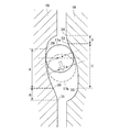
図2は、出力部材18が入力部材16側に最も接近している状態を示している。具体的には、出力部材18にリターンスプリング27のばね力のみが作用しているときに入力部材16と出力部材18とにボール17が挟まれている状態、または入力部材16に生じているトルクに応じて出力部材18が押圧される荷重が、リターンスプリング27のばね力よりも小さいときに入力部材16と出力部材18とにボール17が挟まれている状態を示している。すなわち、入力部材16側に出力部材18を押圧する荷重が、入力部材16から出力部材18を離隔させる荷重よりも大きいときに、入力部材16と出力部材18とにボール17が挟まれている状態を示している。
FIG. 2 shows a state where the
上述したようにカム溝19,20の底面は、入力部材16および出力部材18の端面に対して傾斜して形成されている。そのため、ボール17が上記第1接触部29に接触する位置以外で出力部材18におけるカム溝20の底面に接触していると、出力部材18が入力部材16側に押圧されることにより、ボール17には、出力部材18におけるカム溝20の底面から、出力部材18の円周方向における第1接触部29側に向けた荷重が作用する。そのようにボール17に荷重が作用すると、入力部材16におけるカム溝19の底面には、ボール17から入力部材16を図2における上側に押圧するように円周方向の荷重が作用する。また、出力部材18は回転不能にハウジング3に連結されている。したがって、出力部材18が入力部材16側に押圧されると、入力部材16が図2における上側に回転する。そのように入力部材16が回転すると、入力部材16と出力部材18との間隔が、ボール17の直径よりも大きくなる。そのため、出力部材18が入力部材16側に移動する。
As described above, the bottom surfaces of the
なお、入力部材16が上述するように回転するとともに、出力部材18が軸線方向に移動する際には、ボール17が入力部材16のカム溝19および出力部材18のカム溝20を転がる。そのため、上述したように入力部材16側に出力部材18を押圧する荷重が、入力部材16から出力部材18を離隔させる荷重よりも大きいときには、ボール17が第1接触部29および第4接触部32に接触する位置まで転がる。以下の説明では、ボール17が第1接触部29および第4接触部32に接触している状態を、初期状態と記す。
When the
図2に示す初期状態のときに、突起部22と壁部21との間にオイルを供給すると、突起部22が供給されたオイルの圧力により円周方向に押圧されるので、その油圧に応じたトルクが入力部材16に生じる。そのように入力部材16にトルクが生じると、カム溝19の底面とボール17とが接触している部分では、ボール17の中心に向けた荷重が作用する。そのようにボール17に荷重が作用すると、ボール17とカム溝20とが接触している部分におけるカム溝20の底面の法線方向に荷重が作用する。上述したように出力部材18は、ハウジング3に回転不能に連結されているので、上記のようにカム溝20の底面の法線方向に荷重が作用すると、その荷重のうち軸線方向の成分の荷重が出力部材18を押圧することになる。そのため、出力部材18が入力部材16から離隔する。そのように出力部材18が入力部材16から離隔するとともに、ボール17の中心に向けて入力部材16におけるカム溝19の底面から荷重が作用するため、ボール17は、第3領域Cを第4領域D側に向けて転がり、かつ第1領域Aを第2領域B側に向けて転がる。なお、上記のように出力部材18は、ハウジング3に回転不能に連結されており、入力部材16はハウジング3に相対回転可能に連結されている。そのため、入力部材16は出力部材18と相対回転する。そして、初期状態における入力部材16と出力部材18との位相差を基準として、出力部材18が離隔するように入力部材16が回転することにより、その位相差が大きくなる。
In the initial state shown in FIG. 2, when oil is supplied between the
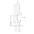
図3は、出力部材18が入力部材16から離隔することにより、押圧部26がドリブンプレート13に接触した時点で、入力部材16と出力部材18とにボール17が挟まれている状態を示している。上述したように第2接触部30は、第1領域Aと第2領域Bとの境界部分であり、同様に第5接触部33は、第3領域Cと第4領域Dとの境界部分であり、押圧部26がドリブンプレート13に接触した時点で、第2接触部30および第5接触部33にボール17が接触する。すなわち、初期状態から、第2接触部30および第5接触部33にボール17が接触している状態までの出力部材18の移動量が、初期状態における押圧部26とドリブンプレート13との隙間と同一になるように、カム溝20の深さ方向における第1接触部29と第2接触部30との偏差L1、およびカム溝19の深さ方向における第4接触部32と第5接触部33との偏差L2が定められている。
FIG. 3 shows a state in which the
一方、出力部材18がドリブンプレート13に接触するまでの間は反力が小さいので、カム溝19,20やボール17の加工誤差などがあると、いずれか一つのボール17とカム溝19またはカム溝20とに滑りが生じる場合がある。そのため、図1に示すように第1領域Aおよび第3領域Cにおけるカム溝19,20の底面の傾斜角度が次第に大きくなるように形成することにより、その滑りを抑制するように構成されている。ここで、ボール17の滑りを抑制することができる作用について説明する。なお、以下の説明では、便宜上、滑りが生じたボール17を第1ボール17aと、滑りが生じていないボール17を第2ボール17bと記す。図4には、第1ボール17aが滑って、第2ボール17bとの位相がずれた状態を示しており、なお、第2ボール17bの位置を破線で示している。具体的には、カム溝19またはカム溝20の加工誤差などによりカム溝19とカム溝20との隙間が大きく形成されている場合、または第1ボール17aの外径が第2ボール17bの外径よりも小さく形成されている場合など、第1ボール17aが第2ボール17bよりも第1領域Aにおける第1接触部29側で、かつ第3領域Cにおける第5接触部33側でカム溝19,20に接触している状態を示している。
On the other hand, since the reaction force is small until the
図4に示すようにボール17は、カム溝19からボール17の中心に向けた荷重を受ける。また、ボール17がカム溝20を押圧する荷重の反力も同様にボール17の中心に向けてカム溝20からボール17に作用する。したがって、図4に示すようにボール17に滑りが生じていない場合には、第2ボール17bと接触するカム溝19,20の部分同士の傾斜角度は同一であって、かつカム溝19における接触部の底面とカム溝20における接触部の底面とが平行になるので、第2ボール17bに入力部材16と出力部材18とから作用する荷重は、同一直線上で、かつ対向して作用する。
As shown in FIG. 4, the
一方、図4に示す第1ボール17aのように滑りが生じて第2ボール17bとの位相がずれた場合には、入力部材16から第1ボール17aが受ける荷重の向きと、出力部材18から第1ボール17aが受ける荷重の向きとが交差する。具体的には、入力部材16から第1ボール17aが受ける荷重のうちの円周方向の成分と、出力部材18から第1ボール17aが受ける荷重のうちの円周方向の成分とが同一方向に作用する。より具体的には、第1ボール17aの位相と第2ボール17bの位相とが一致するように第1ボール17aに円周方向の荷重が作用する。すなわち、第2ボール17bとの位相がずれる方向と対向した方向に入力部材16および出力部材18から第1ボール17aに荷重が作用する。言い換えると、第1ボール17aのように位相がずれると、迅速にその位相のずれを是正するように荷重が作用する。したがって、第1領域Aおよび第3領域Cとは、ボール17の位相を合わせる調芯機能を有している。
On the other hand, when the slip occurs like the
そのため、上述したようにカム溝19,20の底面の傾斜角度を次第に大きくするように形成することにより、ボール17の位相を合わせるためのリテーナなどを設けることなく、カム溝19,20に挟まれたボールの位相がずれることを抑制することができる。その結果、リテーナなどを設ける必要がないので、リテーナなどを設けた場合よりも、部品数を低減することやボールカム機構2の軸長を短縮することができる。また、リテーナなどの部材とボール17との摩擦抵抗などが生じることがないので、荷重の伝達効率を向上させることができる。さらに、上述したように位相がずれることを抑制することができるので、ボール17とカム溝19,20とが滑ることによる摩擦抵抗を減少させることができる。その結果、入力部材16にトルクを生じさせるための油圧を低減させることができる。
Therefore, as described above, the inclination angle of the bottom surface of the
なお、図4では、第1ボール17aが第2ボール17bよりも第1接触部29側および第5接触部33側で接触している状態を示しているが、第1ボール17aが第2ボール17bよりも第2接触部30側および第4接触部32側で接触している場合には、第1ボール17aには、図4における上向きの荷重が作用する。したがって、上述した作用および効果を奏することができる。
FIG. 4 shows a state in which the
上述したように第1領域Aおよび第3領域Cにおけるカム溝19,20をボール17が転がることにより出力部材16がドリブンプレート13に接触すると、出力部材18に作用する反力が比較的大きくなり、上述したようにボール17の位相がずれにくくなる。一方、ドリブンプレート13を押圧するために要求される推力、すなわち、出力部材18を押圧するために要求される荷重が大きくなる。そのため、上述したように第2領域Bおよび第4領域Dにおける傾斜角度を、第2接触部30および第5接触部33の傾斜角度よりも小さく形成して、ボール17から出力部材18が受ける荷重のうちの軸線方向の成分が大きくなるように、すなわち、ドリブンプレート13を押圧するための推力が大きくなるように構成されている。また、図1に示す例では、第1領域Aから第2領域Bにボール17が移動する際に、出力部材18が急激に移動することを抑制するために、第2領域における傾斜角度が、入力部材16の回転方向とは反対側の方向に向けて次第に小さくなるように形成している。そして、第2領域Bおよび第4領域Dにおけるカム溝19,20をボール17が転がることにより、ドリブンプレート13を出力部材18が完全に押圧すると、図5に示すようにボール17が第3接触部31および第6接触部34に接触する。このように出力部材18がドリブンプレート13を完全に押圧する際には、最も大きな推力が要求されるので、第2領域Bおよび第4領域Dにおけるカム溝19,20の底面のうち、第3接触部31および第6接触部34の傾斜角度が最も小さく形成されている。
As described above, when the
上述したように第2領域Bおよび第4領域Dにおけるカム溝19,20の底面の傾斜角度を、第2接触部30や第5接触部33の傾斜角度よりも小さくすること、すなわち、第1領域Aおよび第3領域Cにおけるカム溝19,20の底面のうち、最も傾斜角度が大きい部分よりも、第2領域Bおよび第4領域Dにおけるカム溝19,20の底面の傾斜角度を小さくすることにより、入力部材16に生じるトルクに対する出力部材18が押圧される荷重を大きくすることができる。その結果、供給する油圧を低減することができる。
As described above, the inclination angles of the bottom surfaces of the
また、カム溝19,20の深さは、出力部材18とドリブンプレート13との隙間に応じて定められ、かつ要求される最も大きい推力を出力するためのカム溝19,20の傾斜角度は、多板クラッチ1に要求される伝達トルク容量に基づいて定められる。したがって、カム溝19,20の全域の傾斜角度を上記多板クラッチ1に要求される伝達トルク容量に基づいて定められる傾斜角度に形成すると、カム溝19,20の円周方向の長さが長くなる可能性があるが、上述したように第1領域Aおよび第3領域Cに連なって第2領域Bおよび第4領域Dを形成することにより、カム溝20の円周方向の長さを短くすることができる。そのため、入力部材16および出力部材18に形成するカム溝19,20の数を増加させることができるので、ボール17の一つあたりに作用する面圧を低減することができる。その結果、ボール17の強度を低減することができるので、ボール17の外径を小さくすることができ、ひいてはボールカム機構2の軸長を短くすることができる。または、カム溝19,20の円周方向の長さを短くすることができるので、カム溝19,20を内周側に形成することができる。そのため、ボール17に作用する遠心力を低減することができるので、ボール17が外周側に離脱することを抑制することができる。さらに、カム溝19,20の円周方向の長さを短くすることができるので、入力部材16の単位回転量あたりの出力部材18の移動量を大きくすることができる。その結果、ボールカム機構2の応答性を向上させることができる。
The depth of the
上述した例では、第2領域Bおよび第4領域Dにおけるカム溝19,20の底面の傾斜角度が次第に小さくなるように形成されているが、第2領域Bおよび第4領域Dは、出力部材18を大きな荷重で押圧することができればよいので、図6に示すように第2領域Bおよび第4領域Dにおけるカム溝19,20の底面の傾斜角度を、上述した第3接触部31および第6接触部34と同一の傾斜角度に形成してもよい。すなわち、大きな荷重を出力させるための傾斜角度、より具体的には、第3接触部31や第6接触部34における傾斜角度まで遷移させる領域を備えていなくてもよい。
In the example described above, the inclination angles of the bottom surfaces of the
図6に示すように第2領域Bおよび第4領域Dにおけるカム溝19,20の底面の傾斜角度を、上述した第3接触部31および第6接触部34と同一の傾斜角度に形成することにより、加工精度が低下することを抑制することができる。そのため、出力部材18を押圧する荷重がばらつくなどの性能の低下を抑制することができる。
As shown in FIG. 6, the inclination angles of the bottom surfaces of the
1…多板クラッチ、 2・・・ボールカム機構、 16・・・入力部材、 17・・・ボール、 18・・・出力部材、 19,20・・・カム溝、 29,30,31・・・(出力部材に形成されたカム溝の底面とボールとが接触する)接触部、 32,33,34・・・(入力部材に形成されたカム溝の底面とボールとが接触する)接触部、 A,C・・・(出力部材がドリブンプレートに接触するまでにボールが転がり接触する)領域、 B,D・・・(出力部材がドリブンプレートに接触した後にボールが転がり接触する)領域。 DESCRIPTION OF SYMBOLS 1 ... Multi-plate clutch, 2 ... Ball cam mechanism, 16 ... Input member, 17 ... Ball, 18 ... Output member, 19, 20 ... Cam groove, 29, 30, 31 ... A contact portion (the bottom surface of the cam groove formed on the output member is in contact with the ball), 32, 33, 34 ... (a bottom surface of the cam groove formed on the input member is in contact with the ball), A, C... (Region in which the ball rolls before the output member comes into contact with the driven plate), B, D... Region (in which the ball comes into contact with the driven plate after the output member comes into contact with the driven plate).
Claims (4)
前記各カム溝は、前記位相差が所定量以下のときに前記転動体が転がり接触する前記各カム溝の底面における前記各カム部材の回転面に対する傾斜角度が、前記位相差が大きくなるにつれて大きくなるように形成された第1領域と、前記位相差が所定量以上のときに前記転動体が転がり接触する前記各カム溝の底面の前記回転面に対する傾斜角度が、前記第1領域における最も大きい傾斜角度よりも小さく形成された第2領域とを備えていることを特徴とするカム機構。 The first cam member has a first cam member and a second cam member that are opposed to each other in the axial direction and rotate relative to each other. The first cam member is recessed in the axial direction and has a depth of the depression on the facing surface of the first cam member facing the second cam member. A first cam groove that gradually becomes shallower from the deepest portion toward one of the rotation directions of each cam member is formed, and an axial direction is formed on a surface of the second cam member that faces the first cam member. A second cam groove symmetrical to the first cam groove is formed so as to gradually become shallower from the deepest and deepest part toward the other rotation direction in the rotation direction of each cam member, A rolling element is sandwiched between the cam grooves, and the first cam member and the second cam member rotate relative to each other so that one cam member moves in the axial direction and torque is generated by frictional force. Transmitting When the end surface of the one cam member opposite to the facing surface with respect to the engagement device is disposed at a predetermined interval in the axial direction, and when the phase difference of each cam member is a predetermined amount or more, In the cam mechanism in which one cam member presses the friction engagement device to increase a transmission torque capacity of the friction engagement device,
Each cam groove has a larger inclination angle with respect to the rotation surface of each cam member at the bottom surface of each cam groove with which the rolling element makes rolling contact when the phase difference is a predetermined amount or less, as the phase difference increases. The angle of inclination of the bottom surface of each cam groove with which the rolling element makes rolling contact when the phase difference is equal to or greater than a predetermined amount with respect to the rotational surface is the largest in the first region. And a second region formed smaller than the inclination angle.
Priority Applications (5)
| Application Number | Priority Date | Filing Date | Title |
|---|---|---|---|
| JP2014087824A JP2015206423A (en) | 2014-04-22 | 2014-04-22 | cam mechanism |
| CN201580020694.8A CN106233018A (en) | 2014-04-22 | 2015-04-16 | Cam mechanism |
| US15/305,475 US20170045096A1 (en) | 2014-04-22 | 2015-04-16 | Cam mechanism |
| PCT/IB2015/000506 WO2015162477A1 (en) | 2014-04-22 | 2015-04-16 | Cam mechanism |
| DE112015001968.5T DE112015001968T5 (en) | 2014-04-22 | 2015-04-16 | cam gear |
Applications Claiming Priority (1)
| Application Number | Priority Date | Filing Date | Title |
|---|---|---|---|
| JP2014087824A JP2015206423A (en) | 2014-04-22 | 2014-04-22 | cam mechanism |
Publications (2)
| Publication Number | Publication Date |
|---|---|
| JP2015206423A true JP2015206423A (en) | 2015-11-19 |
| JP2015206423A5 JP2015206423A5 (en) | 2016-07-07 |
Family
ID=53191784
Family Applications (1)
| Application Number | Title | Priority Date | Filing Date |
|---|---|---|---|
| JP2014087824A Pending JP2015206423A (en) | 2014-04-22 | 2014-04-22 | cam mechanism |
Country Status (5)
| Country | Link |
|---|---|
| US (1) | US20170045096A1 (en) |
| JP (1) | JP2015206423A (en) |
| CN (1) | CN106233018A (en) |
| DE (1) | DE112015001968T5 (en) |
| WO (1) | WO2015162477A1 (en) |
Cited By (3)
| Publication number | Priority date | Publication date | Assignee | Title |
|---|---|---|---|---|
| WO2020009187A1 (en) * | 2018-07-06 | 2020-01-09 | 株式会社デンソー | Clutch device |
| JP2020012557A (en) * | 2018-07-06 | 2020-01-23 | 株式会社デンソー | Clutch device |
| WO2021020317A1 (en) * | 2019-07-26 | 2021-02-04 | 株式会社デンソー | Clutch device |
Families Citing this family (6)
| Publication number | Priority date | Publication date | Assignee | Title |
|---|---|---|---|---|
| JP6394627B2 (en) * | 2016-03-09 | 2018-09-26 | トヨタ自動車株式会社 | Lubrication device for engagement mechanism |
| TWI632306B (en) * | 2016-09-10 | 2018-08-11 | 本土股份有限公司 | Clutch structure |
| US10473168B2 (en) * | 2016-09-16 | 2019-11-12 | Dana Automotive System Group, Llc | Ball retaining ball and ramp assembly |
| DE102018124444A1 (en) * | 2018-10-04 | 2020-04-09 | Schaeffler Technologies AG & Co. KG | Ramp actuator and angular contact ball bearing unit with cold-formed outer ring and embossed ramp contour, as well as a method for manufacturing a ramp disc |
| CN113227598B (en) * | 2019-01-11 | 2023-11-14 | Gkn汽车有限公司 | Actuator assembly for clutch assembly of power train of motor vehicle |
| CN114144597A (en) * | 2019-07-26 | 2022-03-04 | 株式会社电装 | Clutch device |
Citations (2)
| Publication number | Priority date | Publication date | Assignee | Title |
|---|---|---|---|---|
| JP2009264536A (en) * | 2008-04-28 | 2009-11-12 | Univance Corp | Driving force transmission device |
| JP2012082895A (en) * | 2010-10-12 | 2012-04-26 | Jtekt Corp | Cam mechanism and driving-force transmission device |
Family Cites Families (15)
| Publication number | Priority date | Publication date | Assignee | Title |
|---|---|---|---|---|
| US3478853A (en) * | 1968-01-08 | 1969-11-18 | Borg Warner | Automatic wear adjuster for friction device |
| US4550817A (en) * | 1984-02-29 | 1985-11-05 | Lambert Brake Corporation | Mechanical clutch |
| US4857033A (en) * | 1985-12-23 | 1989-08-15 | Dana Corporation | Clutch assembly with combined variable and fixed speed pulleys |
| JP2646149B2 (en) | 1990-07-31 | 1997-08-25 | 新日本ホイール工業 株式会社 | Switching multiple disc clutch |
| CN1103140A (en) * | 1993-09-13 | 1995-05-31 | 卢克摩擦片和离合器有限公司 | Seperating apparatus |
| JP2002039228A (en) * | 2000-07-27 | 2002-02-06 | Koyo Seiko Co Ltd | Clutch device |
| US6705446B2 (en) * | 2001-06-07 | 2004-03-16 | Drussel Wilfley Design, Llc | Automatic clutch with manual override control mechanism |
| EP1394437B1 (en) * | 2002-08-30 | 2005-10-12 | Toyoda Koki Kabushiki Kaisha | Electromagnetic clutch |
| JP4363999B2 (en) * | 2004-02-03 | 2009-11-11 | 本田技研工業株式会社 | Clutch device |
| JP2008014423A (en) * | 2006-07-07 | 2008-01-24 | Hitachi Ltd | Wet type friction clutch device |
| JP4905036B2 (en) * | 2006-09-29 | 2012-03-28 | 株式会社ジェイテクト | Driving force transmission device |
| JP2009036341A (en) | 2007-08-03 | 2009-02-19 | Ntn Corp | Pulley unit |
| JP5265947B2 (en) | 2008-03-13 | 2013-08-14 | 株式会社ユニバンス | Driving force transmission device for four-wheel drive vehicles |
| DE102008026902A1 (en) * | 2008-06-05 | 2009-12-10 | Gkn Driveline International Gmbh | Axialverstellvorrichtung with linear drive means |
| WO2012098691A1 (en) * | 2011-01-21 | 2012-07-26 | Aisin Seiki Kabushiki Kaisha | Torque fluctuation absorbing apparatus |
-
2014
- 2014-04-22 JP JP2014087824A patent/JP2015206423A/en active Pending
-
2015
- 2015-04-16 CN CN201580020694.8A patent/CN106233018A/en active Pending
- 2015-04-16 WO PCT/IB2015/000506 patent/WO2015162477A1/en active Application Filing
- 2015-04-16 DE DE112015001968.5T patent/DE112015001968T5/en not_active Withdrawn
- 2015-04-16 US US15/305,475 patent/US20170045096A1/en not_active Abandoned
Patent Citations (2)
| Publication number | Priority date | Publication date | Assignee | Title |
|---|---|---|---|---|
| JP2009264536A (en) * | 2008-04-28 | 2009-11-12 | Univance Corp | Driving force transmission device |
| JP2012082895A (en) * | 2010-10-12 | 2012-04-26 | Jtekt Corp | Cam mechanism and driving-force transmission device |
Cited By (4)
| Publication number | Priority date | Publication date | Assignee | Title |
|---|---|---|---|---|
| WO2020009187A1 (en) * | 2018-07-06 | 2020-01-09 | 株式会社デンソー | Clutch device |
| JP2020012557A (en) * | 2018-07-06 | 2020-01-23 | 株式会社デンソー | Clutch device |
| WO2021020317A1 (en) * | 2019-07-26 | 2021-02-04 | 株式会社デンソー | Clutch device |
| CN114144600A (en) * | 2019-07-26 | 2022-03-04 | 株式会社电装 | Clutch device |
Also Published As
| Publication number | Publication date |
|---|---|
| CN106233018A (en) | 2016-12-14 |
| US20170045096A1 (en) | 2017-02-16 |
| DE112015001968T5 (en) | 2017-01-05 |
| WO2015162477A1 (en) | 2015-10-29 |
Similar Documents
| Publication | Publication Date | Title |
|---|---|---|
| JP2015206423A (en) | cam mechanism | |
| JP7452097B2 (en) | clutch device | |
| US8151964B2 (en) | Multiple disc clutch apparatus | |
| JP6961000B2 (en) | Clutch and vehicle power transmission structure | |
| WO2017033940A1 (en) | Automatic clutch device | |
| US10648533B2 (en) | Torque fluctuation inhibiting device, torque converter and power transmission device | |
| JP6538047B2 (en) | Disc spring | |
| US20210131525A1 (en) | Torque fluctuation inhibiting device and power transmission device | |
| JP2015206423A5 (en) | ||
| US9151333B2 (en) | Gap-filling clutch with ramps | |
| US11927254B2 (en) | Rotary device and power transmission device | |
| JP2014122648A (en) | Ball ramp mechanism, linear motion actuator and electrically-driven disc brake device | |
| JP2009085318A (en) | Torque fluctuation absorbing device | |
| JP2022124036A (en) | Rotation device and power transmission device | |
| JP7376291B2 (en) | Torque fluctuation suppression device and power transmission device | |
| JP6929213B2 (en) | Load generator | |
| JP6672029B2 (en) | Friction engagement device | |
| JP2016121722A (en) | Ball screw device | |
| JP6368102B2 (en) | Friction engagement device | |
| US20210270330A1 (en) | Multiple disc clutch device | |
| JP7522672B2 (en) | Rotating device and power transmission device | |
| JP5803433B2 (en) | Belt type continuously variable transmission | |
| JP2006057804A (en) | Reverse input shut-off device | |
| JP6786329B2 (en) | Reverse input cutoff device | |
| JP6951281B2 (en) | Friction clutch |
Legal Events
| Date | Code | Title | Description |
|---|---|---|---|
| A521 | Request for written amendment filed |
Free format text: JAPANESE INTERMEDIATE CODE: A523 Effective date: 20160523 |
|
| A621 | Written request for application examination |
Free format text: JAPANESE INTERMEDIATE CODE: A621 Effective date: 20160523 |
|
| A131 | Notification of reasons for refusal |
Free format text: JAPANESE INTERMEDIATE CODE: A131 Effective date: 20170221 |
|
| A977 | Report on retrieval |
Free format text: JAPANESE INTERMEDIATE CODE: A971007 Effective date: 20170223 |
|
| A02 | Decision of refusal |
Free format text: JAPANESE INTERMEDIATE CODE: A02 Effective date: 20170815 |