JP2015200875A - image forming apparatus - Google Patents
image forming apparatus Download PDFInfo
- Publication number
- JP2015200875A JP2015200875A JP2015034920A JP2015034920A JP2015200875A JP 2015200875 A JP2015200875 A JP 2015200875A JP 2015034920 A JP2015034920 A JP 2015034920A JP 2015034920 A JP2015034920 A JP 2015034920A JP 2015200875 A JP2015200875 A JP 2015200875A
- Authority
- JP
- Japan
- Prior art keywords
- roller
- transfer belt
- secondary transfer
- recording material
- surface forming
- Prior art date
- Legal status (The legal status is an assumption and is not a legal conclusion. Google has not performed a legal analysis and makes no representation as to the accuracy of the status listed.)
- Granted
Links
- 238000012546 transfer Methods 0.000 claims abstract description 406
- 239000000463 material Substances 0.000 claims abstract description 144
- 230000002093 peripheral effect Effects 0.000 claims description 38
- 238000004804 winding Methods 0.000 claims description 30
- 229920005989 resin Polymers 0.000 claims description 14
- 239000011347 resin Substances 0.000 claims description 14
- 230000014509 gene expression Effects 0.000 claims description 12
- 239000007769 metal material Substances 0.000 claims description 4
- 230000007423 decrease Effects 0.000 claims description 3
- 230000000694 effects Effects 0.000 abstract description 26
- 230000037303 wrinkles Effects 0.000 description 49
- 238000011144 upstream manufacturing Methods 0.000 description 18
- 230000007547 defect Effects 0.000 description 14
- 238000000926 separation method Methods 0.000 description 12
- 238000010586 diagram Methods 0.000 description 11
- 238000002474 experimental method Methods 0.000 description 8
- 238000004140 cleaning Methods 0.000 description 7
- 230000000052 comparative effect Effects 0.000 description 7
- 239000004417 polycarbonate Substances 0.000 description 7
- 239000010410 layer Substances 0.000 description 6
- 229910001220 stainless steel Inorganic materials 0.000 description 5
- 239000010935 stainless steel Substances 0.000 description 5
- 229920001971 elastomer Polymers 0.000 description 4
- 239000005060 rubber Substances 0.000 description 4
- 230000015572 biosynthetic process Effects 0.000 description 3
- 238000000034 method Methods 0.000 description 3
- 239000004642 Polyimide Substances 0.000 description 2
- 239000002216 antistatic agent Substances 0.000 description 2
- 239000006229 carbon black Substances 0.000 description 2
- 238000001816 cooling Methods 0.000 description 2
- 238000009826 distribution Methods 0.000 description 2
- 238000004519 manufacturing process Methods 0.000 description 2
- 229920000515 polycarbonate Polymers 0.000 description 2
- 229920001721 polyimide Polymers 0.000 description 2
- 230000002265 prevention Effects 0.000 description 2
- 230000002411 adverse Effects 0.000 description 1
- 229910052782 aluminium Inorganic materials 0.000 description 1
- XAGFODPZIPBFFR-UHFFFAOYSA-N aluminium Chemical compound [Al] XAGFODPZIPBFFR-UHFFFAOYSA-N 0.000 description 1
- 238000013461 design Methods 0.000 description 1
- 238000011161 development Methods 0.000 description 1
- 230000005684 electric field Effects 0.000 description 1
- 239000000835 fiber Substances 0.000 description 1
- 230000001771 impaired effect Effects 0.000 description 1
- 239000000155 melt Substances 0.000 description 1
- 229910052751 metal Inorganic materials 0.000 description 1
- 239000002184 metal Substances 0.000 description 1
- 239000002356 single layer Substances 0.000 description 1
- 230000000087 stabilizing effect Effects 0.000 description 1
- 230000003746 surface roughness Effects 0.000 description 1
- 238000009864 tensile test Methods 0.000 description 1
- XLYOFNOQVPJJNP-UHFFFAOYSA-N water Substances O XLYOFNOQVPJJNP-UHFFFAOYSA-N 0.000 description 1
Images


Abstract
Description
本発明は、像担持体に担持されたトナー像を、転写ベルトに担持された記録材に転写する画像形成装置に関する。 The present invention relates to an image forming apparatus that transfers a toner image carried on an image carrier onto a recording material carried on a transfer belt.
記録材を転写ベルトに担持させて転写部を通過させ、像担持体の一例である中間転写ベルトに担持されたトナー像を、転写部で、転写ベルトに担持された記録材へ転写する画像形成装置が広く用いられている(特許文献1)。 Image formation in which a recording material is carried on a transfer belt and passed through a transfer portion, and a toner image carried on an intermediate transfer belt, which is an example of an image carrier, is transferred to a recording material carried on the transfer belt by the transfer portion The device is widely used (Patent Document 1).
転写ベルトを用いる画像形成装置では、薄紙のような剛性の低い記録材や波打ち変形した記録材を転写部に通過させてトナー像を転写した場合に、記録材にしわが発生することがある。 In an image forming apparatus using a transfer belt, wrinkles may occur in a recording material when a recording material with low rigidity such as thin paper or a recording material that has undergone undulation deformation is passed through a transfer unit and the toner image is transferred.
そこで、中央部から両端に向かって直径が次第に大きくなる逆クラウン形状を外周面に形成した転写ローラを、転写ベルトを介して像担持体に圧接させることが提案された。特許文献2に示されるように、外周面に逆クラウン形状を付与した転写ローラは、回転軸線方向の端部の搬送速度が中央部の搬送速度よりも大きくなるため、転写部を通過する記録材の後端側が回転軸線方向に押し広げられる。これにより、記録材の搬送方向の両端部や後端部におけるしわ伸ばし効果が発揮されて、記録材の搬送方向の両端部や後端部におけるしわの発生を阻止又は軽減できる可能性があるからである。
In view of this, it has been proposed that a transfer roller having a reverse crown shape whose diameter gradually increases from the central portion toward both ends is pressed against the image carrier via a transfer belt. As shown in
後述するように、転写ベルトの内側面に転写ローラを圧接してトナー像の転写部が形成されている画像形成装置において、転写ローラに逆クラウン形状を付与して記録材のしわ伸ばし効果を確認する実験を行った(表2参照)。すると、転写ベルトの内側面に転写ローラを圧接している場合、転写ローラに逆クラウン形状を付与しても、転写部を通過する際の記録材におけるしわ伸ばし効果が得られないことが判明した。 As will be described later, in an image forming apparatus in which the transfer roller is pressed against the inner surface of the transfer belt to form a toner image transfer portion, a reverse crown shape is applied to the transfer roller to confirm the effect of wrinkling the recording material. (See Table 2). Then, when the transfer roller was pressed against the inner surface of the transfer belt, it was found that even if a reverse crown shape was given to the transfer roller, the effect of wrinkling the recording material when passing through the transfer portion could not be obtained. .
本発明は、転写ベルトの内側面に転写ローラを圧接している画像形成装置において、転写部を通過する記録材に対するしわ伸ばし効果を十分に発揮させることができる画像形成装置を提供することを目的としている。 SUMMARY OF THE INVENTION An object of the present invention is to provide an image forming apparatus in which a transfer roller is pressed against an inner surface of a transfer belt, and a wrinkle-stretching effect for a recording material passing through a transfer portion can be sufficiently exerted. It is said.
本発明の画像形成装置は、トナー像を担持する像担持体と、記録材を搬送する無端状の転写ベルトと、前記転写ベルトを介して前記像担持体に圧接して記録材に対するトナー像の転写部を形成する転写ローラと、前記転写ベルトを張架して記録材の搬送面を形成する搬送面形成ローラと、を備えるものである。そして、前記搬送面形成ローラは、回転軸線方向の両端部に、回転軸線方向の中央部よりも小さな直径で前記転写ベルトを張架する領域を有する。 An image forming apparatus according to the present invention includes an image carrier that carries a toner image, an endless transfer belt that conveys a recording material, and press-contacts the image carrier via the transfer belt to form a toner image on the recording material. The image forming apparatus includes a transfer roller that forms a transfer portion, and a conveyance surface forming roller that stretches the transfer belt to form a conveyance surface of a recording material. The conveying surface forming roller has regions where the transfer belt is stretched at a diameter smaller than that of the central portion in the rotation axis direction at both ends in the rotation axis direction.
本発明の画像形成装置では、搬送面形成ローラの回転軸線方向の両端部の直径が中央部よりも小さいので、両端部と中央部とで直径が等しい場合や両端部の直径が中央部よりも大きい場合に比較して、転写部を通過する際に記録材に発生するしわが少なくなる。これは、実験により確認されている(表1参照)。したがって、転写ベルトの内側面に転写ローラを圧接している画像形成装置において、転写部を通過する記録材に対するしわ伸ばし効果を十分に発揮させることができる。 In the image forming apparatus of the present invention, the diameter of both ends in the rotation axis direction of the transport surface forming roller is smaller than the central portion, so that the diameters at both ends and the central portion are equal or the diameters at both ends are larger than the central portion. Compared to the case where it is large, wrinkles generated in the recording material when passing through the transfer portion are reduced. This has been confirmed by experiments (see Table 1). Therefore, in the image forming apparatus in which the transfer roller is pressed against the inner surface of the transfer belt, the effect of stretching the wrinkles with respect to the recording material passing through the transfer portion can be sufficiently exhibited.
以下、図面を参照して本発明の実施形態を詳細に説明する。 Hereinafter, embodiments of the present invention will be described in detail with reference to the drawings.
<実施の形態1>
(画像形成装置)
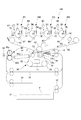
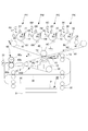
図1は画像形成装置の構成の説明図である。図1に示すように、画像形成装置100は、中間転写ベルト40の上向き面に沿ってプロセスカートリッジの画像形成部PY、PM、PC、PKを配列したタンデム型中間転写方式のフルカラープリンタである。
<
(Image forming device)
FIG. 1 is an explanatory diagram of the configuration of the image forming apparatus. As shown in FIG. 1, the
画像形成部PYでは、感光ドラム1Yにイエロートナー像が形成されて中間転写ベルト40に転写される。画像形成部PMでは、感光ドラム1Mにマゼンタトナー像が形成されて中間転写ベルト40に転写される。画像形成部PC、PKでは、感光ドラム1C、1Kにシアントナー像、ブラックトナー像が形成されて中間転写ベルト40に転写される。
In the image forming unit PY, a yellow toner image is formed on the
中間転写ベルト40に転写された四色のトナー像は、二次転写部T2へ搬送されて記録材Pへ二次転写される。記録材Pは、記録材カセット31から取り出されて、分離ローラ32で1枚ずつに分離されて、レジストローラ13へ送り込まれる。レジストローラ13は、中間転写ベルト40のトナー像にタイミングを合わせて記録材Pを二次転写部T2へ送り込む。
The four color toner images transferred to the
二次転写ベルトユニット36は、二次転写内ローラ42に内側面を支持された中間転写ベルト40に当接して二次転写部T2を形成している。二次転写ローラ10に電圧が印加されることで、中間転写ベルト40上のトナー像が二次転写部T2を搬送される記録材Pへ二次転写される。ここで、記録材Pに転写された各色トナー像は、それぞれ最大反射濃度が1.5〜1.7程度である。最大反射濃度におけるトナー像のトナー載り量は、0.4〜0.6mg/cm2程度である。
The secondary
四色のトナー像を二次転写された記録材Pは、定着前搬送装置61に搬送されて定着装置60へ送り込まれ、定着装置60で加熱加圧を受けて表面に画像を定着される。定着装置60は、ヒータ60cを設けた定着ローラ60aと加圧ローラ60bが形成するニップで所定の加圧力と熱量を与えて記録材Pにトナー像を溶融固着させる。
The recording material P onto which the four-color toner images have been secondarily transferred is conveyed to the
(両面印刷モード)
片面印刷モードでは、定着装置60を通過した記録材Pは、排出ローラ33を通じてそのまま機体外へ排出される。一方、両面印刷モードでは、一度定着した記録材の2面目(裏面)が画像形成面になるようにして、再度二次転写部T2へ給送して記録材Pの両面に画像形成を行う。両面印刷モードでは、記録材の両面に画像形成を行うことにより、記録材の消費を抑えることが可能になっている。
(Duplex printing mode)
In the single-sided printing mode, the recording material P that has passed through the
両面印刷モードでは、定着装置60を通過した記録材Pは、反転搬送路34へ送り込まれ、反転搬送路34でスイッチバック動作を行うことで先後端を入れ替えて両面搬送路35へ搬送される。両面搬送路35は、記録材Pをレジストローラ13に合流させて再び二次転写部T2へ搬送させる。裏面(2面目)にも四色のトナー像を二次転写されて画像を定着された記録材Pは、排出ローラ33を通じて機体外へ排出される。両面印刷モードでは、後述するように、2回目のトナー像の転写に際して記録材にしわが発生し易くなる。
In the double-sided printing mode, the recording material P that has passed through the
(画像形成部)
画像形成部PY、PM、PC、PKは、現像装置5Y、5M、5C、5Kで用いるトナーの色がイエロー、マゼンタ、シアン、ブラックと異なる以外は、ほぼ同一に構成される。以下では、画像形成部PYについて説明し、他の画像形成部PM、PC、PKに関する重複した説明を省略する。
(Image forming part)
The image forming units PY, PM, PC, and PK are substantially the same except that the color of toner used in the developing
画像形成部PYは、感光ドラム1Yを囲んで、帯電装置3Y、露光装置4Y、現像装置5Y、一次転写ローラ6Y、ドラムクリーニング装置7Yを配置している。感光ドラム1Yは、アルミニウム製シリンダの外周面に感光層を形成しており、所定のプロセススピードで矢印R1方向に回転する。
The image forming unit PY surrounds the
帯電装置3Yは、感光ドラム1Yを一様な負極性の電位に帯電させる。露光装置4Yは、画像データを走査線に展開した画像信号に基づいて発生させたレーザービームを回転ミラーで走査して感光ドラム1Yの表面に画像の静電像を書き込む。現像装置5Yは、トナーを感光ドラム1Yに移転させて静電像をトナー像に現像する。不図示の現像剤補給部は、画像形成に伴って現像装置5Yから取り出されただけのトナーを現像装置5Yに補給する。
The
一次転写ローラ6Yは、中間転写ベルト40を押圧して、感光ドラム1Yと中間転写ベルト40の間に一次転写部を形成する。一次転写ローラ6Yに正極性の直流電圧が印加されると、感光ドラム1Yに担持された負極性のトナー像が中間転写ベルト40へ転写される。ドラムクリーニング装置7Yは、感光ドラム1Yにクリーニングブレードを摺擦させて、感光ドラム1Yの表面に付着した転写残トナーを回収する。
The
以上説明したように、画像形成部PY、PM、PC、PKは、トナー像を形成して像担持体の一例である中間転写ベルト40に担持させる。転写ローラの一例である二次転写ローラ10は、転写ベルトの一例である二次転写ベルト12を介して中間転写ベルト40に圧接して記録材に対するトナー像の転写部を形成する。
As described above, the image forming units PY, PM, PC, and PK form toner images and carry them on the
(中間転写ベルト)
中間転写ベルト40は、駆動ローラ43、テンションローラ41、および二次転写内ローラ42に張架され、駆動ローラ43に駆動されて矢印R2方向へ250〜300[mm/sec]で回転する。テンションローラ41は、両端部の不図示の加圧ばねによって外側へ付勢されて中間転写ベルト40の張力をほぼ一定に制御する。二次転写内ローラ42は二次転写部T2を通過する中間転写ベルト40の内側面を支持する。ベルトクリーニング装置44は、中間転写ベルト40にクリーニングブレードを摺擦させて、中間転写ベルト40の表面の転写残トナーを回収する。
(Intermediate transfer belt)
The
中間転写ベルト40は、ポリイミド、ポリカーボネートなどの樹脂または各種ゴム等に帯電防止剤としてカーボンブラックを適当量含有させて体積抵抗率を1×10⁹〜1×10¹⁴[Ω・cm]に調整してある。中間転写ベルト40の厚みは、0.07〜0.1mmである。
The
(上流側ガイド)
二次転写上流上ガイド14及び二次転写上流下ガイド15は、記録材Pがレジストローラ13から二次転写部T2へ搬送されるまでの搬送パスを規制する。
(Upstream guide)
The secondary transfer upstream
二次転写上流上ガイド14は、記録材Pが中間転写ベルト40表面へ近付いてくる挙動を規制する。二次転写上流上ガイド14は、二次転写部T2の上流において記録材Pを案内して記録材を中間転写ベルト40の表面の所定位置に重ね合わせる。
The secondary transfer upstream
二次転写上流下ガイド15は、記録材Pが中間転写ベルト40表面から離れていく挙動を規制する。二次転写上流下ガイド15は、二次転写部T2の上流において記録材Pを案内して記録材を中間転写ベルト40の表面の所定位置に重ね合わせる。
The secondary transfer upstream
(二次転写ベルトユニット)
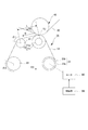
図2は二次転写ベルトユニットの斜視図である。図3は二次転写ベルトユニットの構成の説明図である。図1に示すように、二次転写ベルト12を用いることで、二次転写部T2におけるトナー像の転写後、中間転写ベルト40からの記録材Pの分離が容易になり、記録材Pを安定して定着装置60へ搬送することができる。
(Secondary transfer belt unit)
FIG. 2 is a perspective view of the secondary transfer belt unit. FIG. 3 is an explanatory diagram of the configuration of the secondary transfer belt unit. As shown in FIG. 1, the use of the
図2に示すように、二次転写ベルトユニット36は、4本の張架ローラ、すなわち、二次転写ローラ10、搬送面形成ローラ21、張架ローラ22、及び駆動ローラ23に二次転写ベルト12を掛け回して支持している。二次転写ベルト12の回転方向において、二次転写ローラ10の下流に搬送面形成ローラ21が配置される。搬送面形成ローラ21の下流に張架ローラ22が配置される。張架ローラ22の下流に駆動ローラ23が配置される。駆動ローラ23の下流に二次転写ローラ10が配置される。
As shown in FIG. 2, the secondary
図3に示すように、二次転写ベルト12は、樹脂材料又は金属材料で形成された層を有する無端状のベルト部材である。二次転写ベルト12は、ポリイミド、ポリカーボネートなどの樹脂に帯電防止剤としてカーボンブラックを適当量含有させて体積抵抗率を1×10⁹〜1×10¹⁴[Ω・cm]に調整した樹脂材料で形成されている。二次転写ベルト12は単層構造で厚みは0.07〜0.1mmである。二次転写ベルト12は、引っ張り試験法(JIS K 6301)で測定したヤング率の値が100MPa以上10GPa未満である。
As shown in FIG. 3, the
(二次転写ローラ)
図3に示すように、二次転写ローラ10は、ステンレス丸棒の芯金10aの外周にイオン導電系発泡ゴム(NBRゴム)の弾性層10bを配置して外径24mmに形成されている。二次転写ローラ10は、弾性層10bの表面粗さRz=6.0〜12.0[μm]である。常温常湿環境(N/N:23℃、50%RH)にて2kVを印加して測定した抵抗値が1×105〜1×107[Ω]である。弾性層10bのAsker−C硬度は30〜40程度である。
(Secondary transfer roller)
As shown in FIG. 3, the
二次転写ローラ10には、出力電流が可変の二次転写電源11が接続される。二次転写電源11は、一例として+40〜60μAの転写電流が流れるように出力電圧を自動調整する。二次転写電源11は、二次転写ローラ10に電圧を印加して、中間転写ベルト40と二次転写ベルト12との間に転写電界を形成して、中間転写ベルト40に担持されたトナー像を二次転写ベルト12に担持された記録材Pへ二次転写させる。トナー像の二次転写に伴って二次転写電源11から供給された静電気力によって、記録材Pは、二次転写ベルト12へ吸着される。
A secondary
二次転写ベルト12は、矢印B方向に回転することで、トナー像の二次転写に伴って二次転写ベルト12の表面に吸着された記録材Pを二次転写部T2から下流側へ搬送する。
The
二次転写ローラ10の周面には、200〜300[μm]程度の正クラウン形状が形成されている。二次転写ローラ10に正クラウン形状を形成している理由は、二次転写ローラ10の撓みを相殺して、回転軸線方向における二次転写部T2の中央部が圧抜けすることを防ぐためである。
On the peripheral surface of the
二次転写ベルト12及び中間転写ベルト40は二次転写内ローラ42によって支持されているため、図1に示すように二次転写ローラ10を二次転写内ローラ42へ圧接させたとき、二次転写部T2は、回転軸線方向においてフラットな形状になっている。二次転写ローラ10の表面に200〜300[μm]程度のクラウンが付けられていたとしても、二次転写ベルト12及び中間転写ベルト40に押圧される形となって、二次転写ローラ10が200〜300[μm]程度下方へ撓んでいる。
Since the
(駆動ローラ)
図3に示すように、駆動ローラ23は、モータM3に駆動されて二次転写ベルト12を矢印R3方向に回転させる。二次転写ベルト12の駆動系は、二次転写ベルト12と中間転写ベルト40の速度差を調整可能にするために、中間転写ベルト40の駆動系とは独立して設けられている。駆動ローラ23は、金属ローラ23aの周面に薄層のゴム層23bを固着して、二次転写ベルト12との摩擦力を確保して、駆動時に二次転写ベルト12と駆動ローラ23との間で滑りが生じないようにしている。
(Drive roller)
As shown in FIG. 3, the
駆動ローラ23は、外径が20〜24mmのストレート形状に形成されて、二次転写ベルト12を回転駆動する。ストレート形状の駆動ローラ23で二次転写ベルト12を引っ張ることで、二次転写ベルト12を搬送面形成ローラ21と張架ローラ22の周面に密着させることができる。駆動ローラ23をストレート形状とすることで、駆動ローラ23の下流に位置する二次転写部T2において、張架ローラ22に設けた逆クラウン形状による二次転写ベルト12のしわに起因する転写ムラ等の発生を防止できる。
The
以上説明したように、駆動ローラの一例である駆動ローラ23は、二次転写ベルト12の回転方向における張架ローラ22の下流側で二次転写ベルト12を駆動する。駆動ローラ23は、回転軸線方向の二次転写ベルト12を張架する領域全体が同一の直径である。
As described above, the
(搬送面形成ローラ)
図4は搬送面形成ローラと張架ローラのクラウン形状の説明図である。搬送面形成ローラ21は、二次転写部T2で記録材に発生するしわを防ぐため、周面に正クラウン形状を形成している。搬送面形成ローラ21に形成された正クラウン形状のクラウン量は、二次転写ローラ10に形成しているクラウン量よりも大きい。
(Conveying surface forming roller)
FIG. 4 is an explanatory view of the crown shape of the conveying surface forming roller and the stretching roller. The conveyance
図1に示すように、搬送面形成ローラ21は、二次転写ローラ10の下流に配置された二次転写ベルト12の張架ローラである。二次転写ベルト12の表面に吸着した記録材Pは、搬送面形成ローラ21に沿った二次転写ベルト12の湾曲面で、曲率によって二次転写ベルト12の表面から分離して、定着前搬送装置61に受け渡される。
As shown in FIG. 1, the transport
図4の(a)に示すように、搬送面形成ローラ21は、金属材料の一例であるステンレスの丸棒から削り出して、周面の回転軸線方向の中央部が両端部よりも膨らんだ正クラウン形状に形成されている。回転軸線方向において搬送面形成ローラ21の一番外径が大きい部分の外径をR1maxとし、一番外径が小さい部分の外径をR1minとする。そして、一番外径が大きい部分と一番外径が小さい部分の外径差を正クラウン量ΔR1と定義する。
ΔR1=R1max−R1min
As shown in FIG. 4 (a), the conveyance
ΔR1 = R1max−R1min
実験によって、正クラウン量ΔR1が大きいほど、二次転写部T2で記録材のしわを抑制する効果が大きくなることが確認された。 The experiment confirmed that the larger the positive crown amount ΔR1, the greater the effect of suppressing the wrinkle of the recording material at the secondary transfer portion T2.
実施の形態1では、図3に示すように、二次転写部T2から搬送面形成ローラ21までの距離Lを20〜30mmに設定し、正クラウン量ΔR1を1〜3mmに設定している。また、搬送面形成ローラ21の一番外径が小さい部分の外径R1minは10〜16mmに設定している。
In the first embodiment, as shown in FIG. 3, the distance L from the secondary transfer portion T2 to the transport
正クラウン量ΔR1が大きい搬送面形成ローラ21ほど、二次転写部T2を通過する記録材Pに発生するしわが少なくなる理由は以下のように考えられている。
The reason why the wrinkle generated in the recording material P that passes through the secondary transfer portion T2 is reduced as the conveying
搬送面形成ローラ21の回転軸線に沿った輪郭は、回転軸線方向の中央部が両端部よりも凸になっている。このため、搬送面形成ローラ21の輪郭に案内される二次転写部T2の下流側の二次転写ベルト12は、担持している記録材もろとも、その幅方向(回転方向に直交する方向)の中央部が両端部よりも凸になるように変形している。二次転写ベルト12のこのような変形に伴って、二次転写ベルト12と一体に二次転写部T2を通過している記録材Pには、二次転写部T2の上流側における二次転写ベルト12からの記録材Pの浮き上がりを低くするような力が作用する。また、二次転写ベルト12のこのような変形に伴って、二次転写部T2の下流側で記録材の幅方向(搬送方向に直交する方向)の両端部が中央側へ寄せられて、二次転写部T2の上流側では記録材の後端側を幅方向の外側へ押し広げる方向の力が作用する。これらの力が記録材の幅方向の中央部や後端部におけるしわ伸ばし効果を実現する。
In the contour along the rotation axis of the transport
また、二次転写部T2の下流で記録材Pを上に凸になるように変形させると、記録材Pをストレートに挟み込んでいる二次転写部T2の上流では、下流の上に凸になった部分の反動で記録材Pを下に凸に変形させるような力が作用する。そして、二次転写部T2の上流側で記録材Pを下に凸に変形させるような力が作用すると、二次転写部T2でのしわの原因となる上に凸となる膨らみや波打ちの浮き上がりを減少させることになる。このため、搬送面形成ローラ21を、二次転写ベルト12の回転軸線方向の中央部が両端部よりも表面側に凸になるように変形させ得る形状とすることで、二次転写部T2で生じるしわを軽減することができる。二次転写部T2を挟んだ上流側に、二次転写部T2におけるしわを伸ばす力が効率的に働いて、記録材の波打ちや浮き上がりに起因する二次転写部T2でのしわ発生による画像不良を防止できる。
Further, when the recording material P is deformed so as to protrude upward downstream of the secondary transfer portion T2, the recording material P protrudes upward downstream of the secondary transfer portion T2 sandwiching the recording material P straight. A force that causes the recording material P to be deformed downward is exerted by the reaction of the bent portion. Then, when a force that causes the recording material P to be convexly deformed downward acts on the upstream side of the secondary transfer portion T2, it causes wrinkles in the secondary transfer portion T2 and causes the upward convex bulge and undulation to rise. Will be reduced. For this reason, the conveyance
なお、搬送面形成ローラ21の回転軸線方向の中央部が端部よりも二次転写ベルト12を表面側に凸になるように変形させる形状は、正クラウン形状には限らない。二次転写部T2から搬送面形成ローラ21までの二次転写ベルト12が幅方向の中央部で両端部よりも外側へ膨らむような回転軸線に沿った輪郭線を有する別の形状に置き換えることができる。
In addition, the shape which deform | transforms the center part of the rotation surface direction of the conveyance
また、搬送面形成ローラ21に正クラウン形状を形成する場合、正クラウン形状は、回転軸線に沿って直径が放物線関数的に変化する輪郭線のものには限らない。回転軸線に沿った輪郭線の形状は、双曲線状、県垂線状、円弧状、楕円状等でもよい。
Further, when forming a regular crown shape on the transport
以上説明したように、搬送面形成ローラの一例である搬送面形成ローラ21は、二次転写部T2を搬送されている記録材の搬送方向の先端が到達可能な位置で二次転写ベルト12を張架して記録材の搬送面を形成する。搬送面形成ローラ21は、回転軸線方向の両端部に、中央部よりも小さな直径で二次転写ベルト12を張架する領域を有する。
As described above, the conveyance
(張架ローラ)
搬送面形成ローラ21が記録材Pのしわを抑制する効果は、記録材Pを搬送する二次転写ベルト12が搬送面形成ローラ21の正クラウン形状の周面の形状に密着してタイトに張架されていないと減少する。二次転写ベルト12は、樹脂材料で形成されて硬い性質があるため、搬送面形成ローラ21の正クラウン形状の周面の形状に沿って密着させることは容易ではない。
(Tension roller)
The effect that the conveyance
そこで、実施の形態1では、搬送面形成ローラ21のさらにその下流に、逆クラウン形状の周面を有する張架ローラ22を設けている。張架ローラ22の逆クラウン形状の周面は、二次転写ベルト12を搬送面形成ローラ21の正クラウン形状の周面に沿って過不足なく引っ張って、搬送面形成ローラ21の正クラウン形状の周面に二次転写ベルト12を密着させることができる。
Therefore, in the first embodiment, the stretching
搬送面形成ローラ21の正クラウン形状の両端部と二次転写ベルト12の間に隙間を発生させることなく、搬送面形成ローラ21において二次転写ベルト12の幅方向の中央部を表面側に凸になるように変形させることができる。二次転写ベルト12が硬い材質の樹脂材料で形成されていても、搬送面形成ローラ21の正クラウン形状の両端部まで二次転写ベルト12を密着させて、二次転写ベルト12を搬送面形成ローラ21の正クラウン形状の輪郭に沿って変形させることができる。これにより、二次転写ベルト12上の記録材Pが二次転写部T2を通過する際のしわ発生を抑制する効果を十分に発揮させることができる。
The central portion of the
図4の(b)に示すように、張架ローラ22は、金属材料の一例であるステンレスの丸棒から削り出して、回転軸線方向の両端部が中央部よりも膨らんだ逆クラウン形状を形成されている。回転軸線方向における張架ローラ22の一番外径が大きい部分の外径をR2maxとし、一番外径が小さい部分の外径をR2minとする。そして、一番外径が大きい部分と一番外径が小さい部分との外径差を逆クラウン量ΔR2と定義する。
ΔR2=R2max−R2min
As shown in FIG. 4B, the stretching
ΔR2 = R2max−R2min
実施の形態1では、一番外径が小さい部分の外径R2minを16〜22mmに設定して、ΔR2を1〜3mm程度に設定することができる。 In the first embodiment, the outer diameter R2min of the portion having the smallest outer diameter can be set to 16 to 22 mm, and ΔR2 can be set to about 1 to 3 mm.
ただし、張架ローラ22は、その逆クラウン量ΔR2が所定の基準値から±0.2mmの範囲内に収まるように形成されるのが望ましい。基準値ΔR2aは、転写ベルト12の端部の周長と中央部の周長とが等しくなるように転写ベルト12を張架可能な逆クラウン量である。本実施形態では、逆クラウン量ΔR2と基準値ΔR2aとの差が±0.2mm以内となるように、張架ローラ22は形成される。
ΔR2−ΔR2a≦|0.2|(絶対値)
つまり、逆クラウン量ΔR2と基準値ΔR2aとの差が±0.2mm以内に張架ローラ22が形成されていれば、転写ベルト12の端部の周長と中央部の周長とが等しい状態で、転写ベルト12は張架される。
However, the
ΔR2−ΔR2a ≦ | 0.2 | (absolute value)
That is, if the
以上説明したように、張架ローラの一例である張架ローラ22は、二次転写ベルト12の回転方向における搬送面形成ローラ21の下流側で二次転写ベルト12を張架する。張架ローラ22は、回転軸線方向の両端部に、回転軸線方向の中央部よりも大きな直径で二次転写ベルト12を張架する領域を有する。そして、二次転写ベルト12の端部の周長と、中央部の周長とが等しくなるように、張架ローラ22における回転軸線方向の端部と中央部の直径が設定されている。
As described above, the stretching
(密着条件)
図2に示すように、搬送面形成ローラ21の下流にある張架ローラ22の周面には、搬送面形成ローラ21の正クラウン形状の周面による二次転写ベルト12の中央部と両端部の回転軌道の周長差を打ち消すように、逆クラウン形状が形成されている。
(Close contact conditions)
As shown in FIG. 2, the central surface and both end portions of the
図3に示すように、二次転写ベルト12の搬送面形成ローラ21の回転軸線方向の中央部に対する巻き付き角度をθ1とし、二次転写ベルト12の張架ローラ22の回転軸線方向の中央部に対する巻き付き角度をθ2とする。上述したように、搬送面形成ローラ21の正クラウン量はΔR1であり、張架ローラ22の逆クラウン量はΔR2である。このとき、搬送面形成ローラ21の正クラウン形状の周面に二次転写ベルト12を張った状態で沿わせるためには、ΔR1、ΔR2、θ1、θ2の間に以下の関係式が満たされることが望ましい。
ΔR1×θ1 ≦ ΔR2×θ2
As shown in FIG. 3, the winding angle of the
ΔR1 × θ1 ≦ ΔR2 × θ2
すなわち、搬送面形成ローラ21の最大外径と最小外径の差をΔR1として巻き付き角度をθ1とし、張架ローラ22の最大外径と最小外径の差をΔR2として巻き付き角度をθ2とするとき、ΔR1×θ1≦ΔR2×θ2の関係式を満たすことが望ましい。言い換えれば、逆クラウン形状の張架ローラ22によって二次転写ベルト12の端部を中央より大きく変形させる量を、正クラウンの形状を持つ搬送面形成ローラ21により二次転写ベルト12の中央を凸に変形する量と同等もしくはそれより大きくする。これにより、二次転写ベルト12が樹脂のような硬い物質のときでも、張架ローラ22の二次転写ベルト12を端部方向に引っ張る力によって、二次転写ベルト12を搬送面形成ローラ21の長手方向全域にわたって沿わせることが可能になる。そのため、上記のような大小関係が成り立つことが望ましい。
That is, when the difference between the maximum outer diameter and the minimum outer diameter of the conveying
(比較実験)
図3に示す二次転写ローラ10、搬送面形成ローラ21、張架ローラ22、駆動ローラ23の周面形状を異ならせて二次転写ベルトユニット36を試作した。そして、試作した二次転写ベルトユニット36を画像形成装置100に搭載して、薄紙の両面印刷モードにおける記録材のしわ発生状態を比較した。後述するように、薄紙の両面印刷モードでは、記録材のしわ発生が多いからである。なお、実験に用いた二次転写ローラ10は、上述したようにわずかな正クラウン形状に形成されているが、実質的な意味でストレートと表記している。
(Comparative experiment)
A secondary
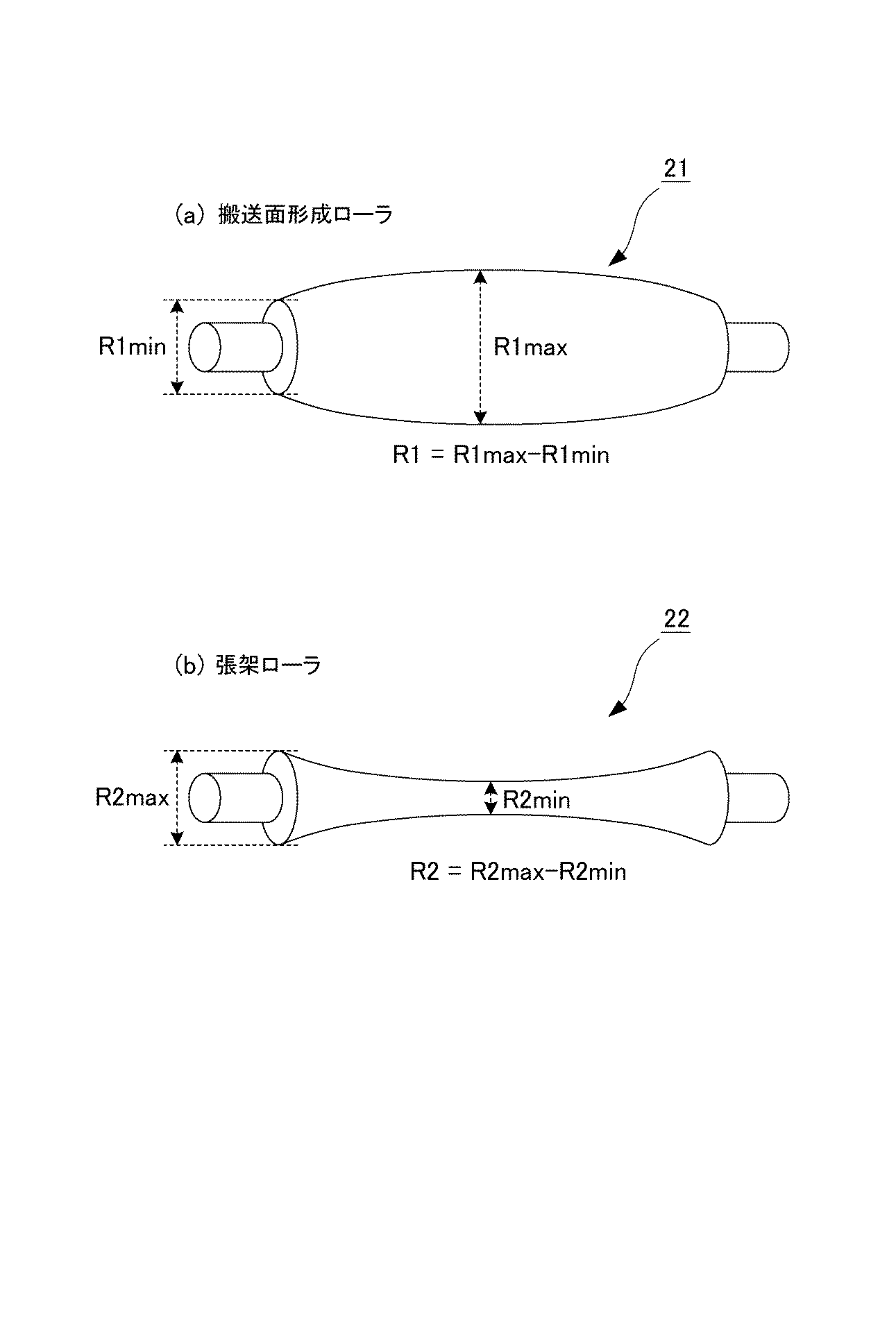
表1に示すように、搬送面形成ローラ21の周面を正クラウン形状にした実施例1、2の場合、薄紙の両面印刷モードにおける記録材のしわ発生防止に効果が得られた。特に、張架ローラ22の周面を逆クラウン形状にした実施例1では、記録材のしわ発生防止に関して大きな効果が得られた。
As shown in Table 1, in Examples 1 and 2 in which the peripheral surface of the conveying
比較例1は、二次転写ベルト12が無い場合には従来の構成に該当しており、二次転写ベルト12が無い場合には記録材のしわ発生防止に関して大きな効果が得られる。しかし、二次転写ベルト12が張架された状態ではしわ発生防止の効果が消滅した。
The comparative example 1 corresponds to the conventional configuration when the
比較例2は、しわ発生防止の効果が無い。比較例3、4、5は、逆効果となってしわ発生が著しくなった。 Comparative Example 2 is not effective in preventing wrinkle generation. In Comparative Examples 3, 4, and 5, the wrinkles were remarkable due to the adverse effect.
したがって、搬送面形成ローラ21の周面を正クラウン形状とすることで、しわ発生防止効果が得られ、さらに張架ローラ22を逆クラウン形状とすることでしわ発生防止効果が高まる。
Therefore, the effect of preventing the occurrence of wrinkles can be obtained by making the peripheral surface of the conveying
(比較例1の補足説明)
特許文献3に記載される画像形成装置では、定着装置で発生する波打ちを軽減するために、定着後の記録材を急速冷却している。しかし、記録材を急速に冷却するシステムを設けようとすると大掛かりな冷却装置が必要になるため、製造及び運転のコストが増加し、画像形成装置が大型化する、消費電力が増大するといった問題が出てくる。
(Supplementary explanation of Comparative Example 1)
In the image forming apparatus described in Patent Document 3, the recording material after fixing is rapidly cooled in order to reduce waviness generated in the fixing device. However, if a system for rapidly cooling the recording material is provided, a large-scale cooling device is required, which increases manufacturing and operating costs, increases the size of the image forming apparatus, and increases power consumption. Come out.
特許文献2に示される画像形成装置では、トナー像の転写部を形成する転写ローラの周面に逆クラウン形状を形成して、記録材の幅方向の端部が外側へ伸びるような搬送速度分布を二次転写部T2に発生させている。これにより、二次転写部や定着装置のニップ部において記録材のしわを外へ伸ばしていくことができる。
In the image forming apparatus disclosed in
したがって、上述した比較例1のように、二次転写ローラ10の周面に逆クラウン形状を形成しておけば、定着装置60で波打ちが発生した記録材Pでも、二次転写部T2を通過する際にしわが発生しないことが期待される。しかし、上述したように、比較例1ではそのような効果は存在しない。この理由は以下のように考えられている。
Therefore, if the reverse crown shape is formed on the peripheral surface of the
記録材Pを安定して搬送するために二次転写ベルト12が二次転写ローラ10の表面にタイトに掛け回されている場合、二次転写ベルト12は張架する張力と対向する二次転写内ローラ42とによって平坦に変形している。このため、記録材のしわを伸ばすような速度分布を形成することができない。
When the
すなわち、周面が逆クラウン形状の二次転写ローラに二次転写ベルトを張架させた場合、二次転写ローラの逆クラウン形状によって紙のしわを十分に伸ばすことができない。定着装置60で発生した波打ちに起因して二次転写部T2でしわによる転写ムラが発生し易くなる。
That is, when a secondary transfer belt is stretched around a secondary transfer roller having a reverse crown shape on the peripheral surface, the wrinkle of the paper cannot be sufficiently stretched due to the reverse crown shape of the secondary transfer roller. Due to the waviness generated in the fixing
これに対して実施の形態1では、二次転写部T2において二次転写ローラ10の周面の形状によって記録材のしわを十分に伸ばすことができない場合でも、二次転写部T2で発生するしわを防いで、高画質の成果物を出力できる。
On the other hand, in the first embodiment, even when the wrinkles of the recording material cannot be sufficiently stretched due to the shape of the peripheral surface of the
(薄紙の両面印刷モード)
図5は薄紙の両面印刷モードにおける記録材のしわの発生の説明図である。図1に示すように、両面印刷モードでは、記録材Pへ1回目のトナー像を定着するために、定着装置60で熱と圧力を加えた際に、ある一定の水分を含んでいた記録材Pから水分が失われ、その後、記録材Pは周囲から急速に水分を吸収する。記録材Pの含有水分量の変化が定着装置60を通過する前後で急激に起こることで、記録材Pの紙の繊維が部分的に伸び縮みして記録材に波打ちが発生することがある。含有水分量の変化は、記録材の中央部に比べて端部ほど著しいため、記録材の両端部が中央部に比べて長くなって、端部が波うつ、波うちと呼ばれる現象が定着装置60を通過した記録材Pに発生し易くなる。
(Thin paper duplex printing mode)
FIG. 5 is an explanatory diagram of the occurrence of wrinkles in the recording material in the thin paper duplex printing mode. As shown in FIG. 1, in the double-sided printing mode, a recording material containing a certain amount of water when heat and pressure are applied by the fixing
そして、波うちが発生した記録材Pの裏面にトナー像を転写するために二次転写部T2へ記録材Pを再度搬送した場合、記録材Pの端部の波打った部分がその長さを合わせようと中央によっていき、二次転写部T2を通過する際にしわに変化する。二次転写部T2で著しいしわが発生した場合、著しく脆い記録材であれば、記録材そのものがしわの折り目で折れてしまう。記録材が折れるほどではなくても、しわの発生した部分と発生しない部分とでトナー像の転写ムラが発生するため、出力画像の品質は確実に損なわれる。定着装置60で発生する記録材の波打ちは、剛度の低い薄紙ほどひどくなり、波打ちによる二次転写部T2でのしわによる転写ムラも薄紙ほど発生し易くなる。
When the recording material P is conveyed again to the secondary transfer portion T2 in order to transfer the toner image to the back surface of the recording material P where the waviness has occurred, the length of the wavy portion at the end of the recording material P is the length. The wrinkles are changed when passing through the secondary transfer portion T2 in accordance with the center so as to match. When a significant wrinkle is generated at the secondary transfer portion T2, if the recording material is extremely brittle, the recording material itself is folded at the crease. Even if the recording material is not bent, the toner image transfer unevenness occurs between the wrinkled portion and the non-wrinkled portion, so that the quality of the output image is surely impaired. The undulation of the recording material generated in the fixing
図5の(a)に示すように、波打ちが発生している記録材Pは、幅方向の両端部の搬送方向の長さよりも中央部の搬送方向の長さが長くなっている。図5の(b)に示すように、波打ちが発生している記録材Pを平坦な二次転写ベルト12の表面に張り付けると、両端部と中央部とにおける搬送方向の長さ差によって、記録材の幅方向の中央部が二次転写ベルト12から離れるよう上に凸に膨らむ。記録材Pの幅方向の中央部が膨らんだ状態のまま二次転写部T2のニップに搬送されると、幅方向の中央部の膨らみが搬送方向Bの反対側である上流側に寄せられていく。図5の(c)に示すように、幅方向の中央部の膨らみが二次転写部T2のニップ圧力に耐え切れなくなると、幅方向の中央部の膨らみがニップ圧力で押し潰されてしわになる。
As shown in FIG. 5A, the recording material P in which undulation is generated has a length in the transport direction at the center portion longer than the length in the transport direction at both end portions in the width direction. As shown in FIG. 5B, when the recording material P in which undulation is generated is stuck on the surface of the flat
上述のように、本実施形態では、例え「波打ち」が発生したとしても記録材Pにしわを生じさせないために、搬送面形成ローラ21を正クラウン形状に形成し、且つ、張架ローラ22を逆クラウン形状に形成している。この場合に、後述の実験によって、搬送面形成ローラ21の回転軸線方向の中央部における二次転写ベルト12の巻き付き長さと、端部における二次転写ベルト12の巻き付き長さとの差が大きいほど、しわが生じ難くなることが確認された。表3は、実験から得られた広がり量と画像不良の発生有無との関係を示す。表3では、画像不良が発生した場合を「×」で示し、画像不良が発生していない場合を「○」で示している。広がり量は、転写時に二次転写部T2の上流側で記録材Pが幅方向(搬送方向に直交する方向)の外側へ押し広げられて変形した場合の記録材Pの変形量である。表3から理解できるように、広がり量が3mm以上である場合には画像不良が生じていない。
As described above, in the present embodiment, even if “waving” occurs, the conveyance
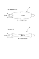
上述の広がり量について、図6を用いて説明する。図6左図は二次転写部T2を通過させる前(通紙前)の記録材Pの状態を示し、図6右図は二次転写部T2を通過させた後(通紙後)の記録材Pの状態を示す。記録材Pとして、図6左図に示すように、搬送方向に沿って後端側を短冊状に切断したA3サイズの用紙を用いた。ここでは、短冊の帯数を5個とし、各帯間の隙間を20mmに、帯の長さを200mmに形成している。この用紙が二次転写部T2を通過すると、図6右図に示すように、用紙の後端側が幅方向外側に向かって広がる。そこで、二次転写部T2を通過させる前と通過させた後の用紙の幅をそれぞれ測り、二次転写部T2通過前の用紙の後端幅Gと二次転写部T2通過後の用紙の後端幅Hとの差を広がり量とした。 The spread amount will be described with reference to FIG. 6 shows the state of the recording material P before passing through the secondary transfer portion T2 (before paper passing), and the right diagram in FIG. 6 shows the recording after passing through the secondary transfer portion T2 (after paper passing). The state of the material P is shown. As the recording material P, as shown in the left diagram of FIG. 6, A3 size paper whose rear end side was cut into a strip shape along the transport direction was used. Here, the number of strips is five, the gap between the strips is 20 mm, and the strip length is 200 mm. When the sheet passes through the secondary transfer portion T2, the rear end side of the sheet spreads outward in the width direction as shown in the right diagram of FIG. Therefore, the width of the paper before and after passing through the secondary transfer portion T2 is measured, respectively, and the trailing edge width G of the paper before passing through the secondary transfer portion T2 and the back of the paper after passing through the secondary transfer portion T2. The difference from the end width H was defined as the spread amount.
そして、二次転写ベルト12の巻き付き長さの差を変えながら上記用紙を二次転写部T2に通過させ、その時々の広がり量と画像不良の発生有無とを調べた。図7に、実験結果を示す。図7は、実験によって得られた、二次転写ベルト12の巻き付き長さの差と広がり量との関係を示している。また、画像不良の発生有無との関係も示している。図7に示すように、広がり量が所定値(ここでは3mm)より大きい場合には、画像不良が発生しなかった。そして、広がり量が所定値(3mm)より大きくなるのは、巻き付き長さの差が0.8mmより大きい場合であった。このことから、巻き付き長さの差が0.8mm以下である場合には画像不良が生じやすく、0.8mmより大きい場合には画像不良が生じ難い、ということが理解できる。言い換えれば、記録材Pに対するしわ伸ばし効果は、巻き付き長さの差を0.8mmより大きくした場合に得られやすい、と言える。
Then, the sheet was passed through the secondary transfer portion T2 while changing the difference in the winding length of the
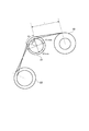
上述の二次転写ベルト12の巻き付き長さについて、図8を用いて説明する。図8に示すように、本実施形態では、回転軸線方向において搬送面形成ローラ21の一番外径が大きい部分の外径をR1maxとし、一番外径が小さい部分の外径をR1minとする。そして、二次転写ベルト12の搬送面形成ローラ21の回転軸線方向の中央部に対する巻き付き角度をθ1とし、二次転写ベルト12の搬送面形成ローラ21の回転軸線方向の端部に対する巻き付き角度をθ3とする。この場合、中央部と端部での巻き付き長さは、それぞれ「(R1max/2)×θ1」、「(R1min/2)×θ3」で表わされる。
The winding length of the
上述したように、これらの巻き付き長さの差が0.8mmより大きければ、記録材Pに対するしわ伸ばし効果が得られる。すなわち、しわ発生を抑制するためには、R1max、R1min、θ1、θ3が以下の関係式を満たせばよい。
0.8<{(R1max/2)×θ1−(R1min/2)×θ3}
As described above, if the difference between the winding lengths is larger than 0.8 mm, the wrinkle stretching effect on the recording material P can be obtained. That is, in order to suppress the generation of wrinkles, R1max, R1min, θ1, and θ3 may satisfy the following relational expression.
0.8 <{(R1max / 2) × θ1− (R1min / 2) × θ3}
記録材Pに対するしわ伸ばし効果は、上述した巻き付き長さの差が大きいほどより大きい効果が得られる。そこで、搬送面形成ローラ21に二次転写ベルト12を大きく巻き付けて、巻き付き長さの差をより大きくすることが考えられる。しかし、正クラウン形状の搬送面形成ローラ21に二次転写ベルト12を大きく巻き付けた場合、二次転写ベルト12の回転が阻害されたり、二次転写ベルト12が破断されたりし得る。そこで、二次転写ベルト12にかかる応力を考慮したうえで、より大きなしわ伸ばし効果が得られるように、本実施形態ではさらにR1max、R1min、θ1、θ3が以下の関係式を満たす必要がある。
E/F>16.3×{(R1max/2)×θ1−(R1min/2)×θ3}−2.4
The wrinkle-stretching effect on the recording material P is greater as the difference in the winding length is larger. Therefore, it can be considered that the
E / F> 16.3 × {(R1max / 2) × θ1− (R1min / 2) × θ3} −2.4
ここで、E(MPa)は二次転写ベルト12の降伏強度であり、F(kg)は二次転写ベルト12にかかるテンションである。
Here, E (MPa) is the yield strength of the
この関係式は、図9に示す実験結果を数値解析することにより得られる。図9は、実験によって得られた、二次転写ベルト12の巻き付き長さの差と二次転写ベルト12にかかる最大応力との関係を示している。図9に示した実験結果を解析して、最大応力Em(MPa)と巻き付き長さの差(mm)の関係を表す近似曲線を求めた。この近似曲線を表す近似式を示す。
Em=16.3×{(R1max/2)×θ1−(R1min/2)×θ3}−2.4
This relational expression is obtained by numerical analysis of the experimental result shown in FIG. FIG. 9 shows the relationship between the difference in the winding length of the
Em = 16.3 × {(R1max / 2) × θ1− (R1min / 2) × θ3} −2.4
そして、テンションF(kg)と最大応力Em(MPa)は比例関係であることが分かる。そこで、上述の近似式をテンションF(kg)で割ると、次に示す式が導かれる。
Em/F=16.3×{(R1max/2)×θ1−(R1min/2)×θ3}−2.4
It can be seen that the tension F (kg) and the maximum stress Em (MPa) are in a proportional relationship. Therefore, when the above approximate expression is divided by the tension F (kg), the following expression is derived.
Em / F = 16.3 × {(R1max / 2) × θ1− (R1min / 2) × θ3} −2.4
さらに、二次転写ベルト12の降伏強度E(MPa)は、最大応力Em(MPa)より大きくなければならない。以上より、上述した関係式が求められる。この関係式は、二次転写ベルト12の巻き付き長さの差の上限を示す。
E/F>16.3×{(R1max/2)×θ1−(R1min/2)×θ3}−2.4
Furthermore, the yield strength E (MPa) of the
E / F> 16.3 × {(R1max / 2) × θ1− (R1min / 2) × θ3} −2.4
なお、本実施形態では、二次転写ベルト12の降伏強度E(MPa)は100〜150(MPa)である。また、テンションF(kg)は1.5〜4(kg)である。
In this embodiment, the yield strength E (MPa) of the
本実施形態では、巻き付き長さの差は例えば1.2mm程度とするのが望ましい。この値は0.8(mm)より大きいので、記録材Pに対するしわ伸ばし効果が十分に得られる。また、この場合、二次転写ベルト12にかかる応力は二次転写ベルト12の降伏強度よりも小さくなる。そのため、二次転写ベルト12の回転が阻害されたり、二次転写ベルト12が破断されたりすることがない。
In the present embodiment, the difference in the winding length is preferably about 1.2 mm, for example. Since this value is larger than 0.8 (mm), the wrinkle stretching effect on the recording material P can be sufficiently obtained. In this case, the stress applied to the
搬送面形成ローラ21は、二次転写ベルト12から記録材Pを曲率分離する湾曲面を二次転写ベルト12に形成する分離ローラを兼ねている。搬送面形成ローラ21が正クラウン形状に形成されている場合、剛度の低い薄紙は二次転写ベルト12に沿うように二次転写ベルト12に吸着されたまま搬送される。しかし、剛度の高い厚紙は二次転写ベルト12に沿うようにはならず、二次転写ベルト12から離れてしまうため、厚紙は搬送面形成ローラ21より下流では安定して二次転写ベルト12で搬送できない。薄紙から厚紙まで、記録材Pを安定して定着装置60まで搬送することを考えると、搬送面形成ローラ21は分離ローラを兼ねて、その後、定着装置60までは定着前搬送装置61によって搬送されることが望ましい。
The transport
(実施の形態1の効果)
実施の形態1では、二次転写部T2の下流にある搬送面形成ローラ21の周面を正クラウン形状にして二次転写ベルト12の幅方向の中央部が両端部よりも表面側に凸になるように変形させるため、記録材にしわが発生しにくくなる。薄紙の記録材でも、両面印刷モードでも記録材にしわが発生しにくくなる。搬送面形成ローラ21の周面を正クラウン形状にすることで、二次転写ベルト12上の記録材Pは、二次転写部T2を挟んだ下流側で表面側が凸になるように変形する。紙のような剛体は、二次転写部T2のニップ部で挟持されると、反動で二次転写部T2の付近に下に凸になるような力が働く。この力は、二次転写部T2の上流側においてしわの原因となる記録材の上に凸となる膨らみを減少させるため、二次転写部T2で発生するしわを抑制することができる。
(Effect of Embodiment 1)
In the first embodiment, the circumferential surface of the conveyance
実施の形態1では、張架ローラ22の周面を逆クラウン形状にして二次転写ベルト12の幅方向の中央部が両端部よりも表面側に凹となるように変形させるため、二次転写ベルト12が搬送面形成ローラ21に隙間なく接触する。搬送面形成ローラ21の下流の張架ローラ22の周面が逆クラウン形状であるため、二次転写ベルト12が硬い樹脂ベルトであっても、二次転写ベルト12は、搬送面形成ローラ21の周面の正クラウン形状にきちんと張られた状態で掛け回される。この状態にすることで二次転写部T2の下流の記録材Pは、より中央が膨らんでいる形状に沿って搬送される。このため、搬送面形成ローラ21の周面を正クラウン形状にする効果が高まって、搬送面形成ローラ21による記録材Pのしわを伸ばす効果が顕著になり、定着装置60で発生する波うち起因のしわによる画像不良も軽減される。
In the first embodiment, since the circumferential surface of the
実施の形態1では、搬送面形成ローラ21は、二次転写ベルト12から記録材Pを曲率分離させる分離ローラを兼ねているため、搬送面形成ローラ21の下流側に独立した分離ローラを配置する必要がない。このため、二次転写ベルトユニット36の部品点数が削減されて小型化が達成される。
In the first embodiment, the conveyance
部品点数の削減の観点からは、特許文献3に示されるように、二次転写部T2から定着装置60までを1個の転写ベルトユニットで構成することが考えられる。搬送面形成ローラ21の下流に搬送面形成ローラを配置し、搬送面形成ローラの下流に独立した分離ローラを配置する構成である。このとき、搬送面形成ローラの周面が正クラウン形状であっても、剛度の低い薄紙は、二次転写ベルト12に沿うように二次転写ベルト12に吸着されたまま搬送される。しかし、剛度の高い厚紙は、二次転写ベルト12に沿うようにはならず、二次転写ベルト12から離れてしまうため、厚紙は、搬送面形成ローラより下流では安定して搬送できない。
From the viewpoint of reducing the number of parts, as shown in Patent Document 3, it is conceivable that the secondary transfer portion T2 to the fixing
したがって、薄紙から厚紙まで、二次転写部T2から定着装置60まで記録材Pを安定して搬送しようとすると、図1に示すように、搬送面形成ローラ21は分離ローラを兼ねて二次転写ローラ10に近接した位置に配置することが望ましい。搬送面形成ローラ21から定着装置60までの空間は、別の搬送手段である定着前搬送装置61によって搬送されることが望ましい。
Accordingly, when the recording material P is to be stably conveyed from the thin paper to the thick paper and from the secondary transfer portion T2 to the fixing
実施の形態1によれば、二次転写部T2に供給される記録材Pが、一度、定着装置60を通って波打ちが発生している状態であっても、波打ち起因の二次転写部T2でのしわによる画像不良を確実に減少させることができる。
According to the first embodiment, even if the recording material P supplied to the secondary transfer portion T2 is once undulated through the fixing
<実施の形態2>
図10は実施の形態2の画像形成装置の構成の説明図である。図1に示すように実施の形態1では、二次転写ベルト12が4本の張架ローラによって台形に張架されていた。これに対して実施の形態2では、二次転写ベルト12が3本の張架ローラによって三角形に張架されている。二次転写ベルト12の張架形状及び張架ローラの数以外の構成は実施の形態1と同様であるため、以下の説明中、実施の形態1と共通する構成には図1と共通の符号を付して重複する説明を省略する。
<
FIG. 10 is an explanatory diagram of a configuration of the image forming apparatus according to the second embodiment. As shown in FIG. 1, in the first embodiment, the
図10に示すように、二次転写ベルトユニット36Bの二次転写ベルト12は、搬送面形成ローラ21、張架ローラ22、及び二次転写ローラ10によって張架されている。二次転写ローラ10の下流に二次転写ベルト12の分離ローラを兼ねる搬送面形成ローラ21が配置される。搬送面形成ローラ21の下流に張架ローラ22が配置される。張架ローラ22の下流に二次転写ローラ10が配置される。
As shown in FIG. 10, the
実施の形態2では、実施の形態1のような駆動ローラ(23)及び駆動ローラを駆動するモータ(M3)が設けられず、二次転写ベルト12は、中間転写ベルト40に当接して従動回転する。
In the second embodiment, the driving roller (23) and the motor (M3) for driving the driving roller are not provided as in the first embodiment, and the
図4の(a)に示すように、搬送面形成ローラ21は、周面が正クラウン形状である。搬送面形成ローラ21の一番外径が大きい部分の外径をR1max、一番外径が小さい部分の外径をR1minとし、正クラウン量ΔR1を次式のように定義する。
ΔR1=R1max−R1min
As shown in FIG. 4A, the conveying
ΔR1 = R1max−R1min
このとき、実施の形態2では、R1minは10〜16mm、ΔR1は1〜3mm程度である。
At this time, in
図4の(b)に示すように、張架ローラ22は、周面が逆クラウン形状である。張架ローラ22の一番外径が大きい部分の外径をR2maxとし、一番外径が小さい部分の外径をR2minとし、逆クラウン量ΔR2を次式のように定義する。
ΔR2=R2max−R2min
As shown in FIG. 4B, the
ΔR2 = R2max−R2min
このとき、実施の形態2では、R2minは16〜22mm、ΔR2は1〜3mm程度である。
At this time, in
搬送面形成ローラ21は、二次転写ベルト12から記録材Pを曲率分離する湾曲面を二次転写ベルト12に形成する分離ローラを兼ねている。搬送面形成ローラ21の周面が正クラウン形状の場合、剛度の低い薄紙は二次転写ベルト12に沿うように二次転写ベルト12に吸着されたまま搬送される。しかし、剛度の高い厚紙は二次転写ベルト12に沿うようにはならず、二次転写ベルト12から離れてしまうため、厚紙は搬送面形成ローラ21より下流では安定して二次転写ベルト12で搬送できない。薄紙から厚紙まで、記録材Pを安定して定着装置60まで搬送することを考えると、搬送面形成ローラ21は分離ローラを兼ねて、その後、定着装置60までは定着前搬送装置61によって搬送されることが望ましい。
The transport
正クラウン形状の搬送面形成ローラ21の下流に配置された張架ローラ22が逆クラウン形状であるため、二次転写ベルト12は、硬い樹脂ベルトであっても、搬送面形成ローラ21にきちんと張られた状態で掛け回される。
Since the
実施の形態2では、実施の形態1よりも二次転写ベルトユニット36Bの部品点数が少なくて済み低コストに製造できる。張架ローラ22の下流が二次転写ローラ10となるシンプルな系ではあるが、実施の形態1と同様に、二次転写部T2におけるしわの発生を抑制できる。二次転写部T2に供給される記録材Pが定着装置60を通って波打ちが発生している状態であっても、波打ち起因の二次転写部T2でのしわによる画像不良を減少させることができる。したがって、二次転写部T2における波打ち起因のしわを防止するためには、二次転写ローラ10以外の張架ローラは2本でもよい。
In the second embodiment, the number of parts of the secondary
<その他の実施の形態>
図11は、その他の実施の形態の一例の説明図である。本発明は、実施の形態1、2で説明した構成、制御、材料、設計、寸法には限定されない。図1に示す二次転写ベルトユニット36は、二次転写ローラ10を除いた張架ローラが4本以上でもよい。搬送面形成ローラ21は、分離ローラを兼ねる必要はない。実施の形態1の構成は、両面印刷モードの2回目のトナー像の転写においてのみ効果を発揮するものではない。
<Other embodiments>
FIG. 11 is an explanatory diagram of an example of another embodiment. The present invention is not limited to the configuration, control, material, design, and dimensions described in the first and second embodiments. The secondary
図11の(a)に示すように、搬送面形成ローラ21は、回転軸線方向で直径が連続的に変化するもの、あるいは周面が正クラウン形状のものには限定されない。二次転写ベルト12を幅方向の中央部が両端部より表面側に凸になるように変形させることができる搬送面形成ローラ21の輪郭形状は、正クラウン形状には限らない。ステンレスの中心軸21aの端部に樹脂ローラ21b、21dを固定し、中央部に樹脂ローラ21cを固定してもよい。
As shown in FIG. 11A, the conveying
図11の(b)に示すように、張架ローラ22は、回転軸線方向で直径が連続的に変化するもの、あるいは周面が逆クラウン形状のものには限定されない。幅方向の中央部が両端部より内周側に凸になるように変形させることができる張架ローラ22の輪郭形状は、逆クラウン形状には限らない。ステンレスの中心軸22aの端部に樹脂ローラ22b、22dを固定し、中央部に樹脂ローラ22cを固定してもよい。
As shown in FIG. 11B, the stretching
トナー像を担持して二次転写ベルト12に担持された記録材Pへトナー像を転写する像担持体は像担持体の一例に過ぎない中間転写ベルト40には限定されない。二次転写ベルト12に相当する転写ベルトへ、像担持体の別の一例である感光ドラムを当接させて、感光ドラムから転写ベルトへトナー像を転写してもよい。
The image carrier that carries the toner image and transfers the toner image to the recording material P carried on the
1 感光ドラム、3 帯電装置、4 露光装置、5 現像装置、6 一次転写ローラ
7 ドラムクリーニング装置、10 二次転写ローラ、11 二次転写電源
12 二次転写ベルト、13 レジストローラ、14 二次転写上流上ガイド
15 二次転写上流下ガイド、21 搬送面形成ローラ
22 張架ローラ、23 駆動ローラ、40 中間転写ベルト
41 テンションローラ、42 二次転写内ローラ、43 駆動ローラ
44 ベルトクリーニング装置、60 定着装置、61 定着前搬送装置
P 記録材、T2 二次転写部
DESCRIPTION OF
Claims (10)
記録材を搬送する無端状の転写ベルトと、
前記転写ベルトを介して前記像担持体に圧接して記録材に対するトナー像の転写部を形成する転写ローラと、
前記転写ベルトを張架して記録材の搬送面を形成する搬送面形成ローラと、を備え、
前記搬送面形成ローラは、回転軸線方向の両端部に、回転軸線方向の中央部よりも小さな直径で前記転写ベルトを張架する領域を有することを特徴とする画像形成装置。 An image carrier for carrying a toner image;
An endless transfer belt for conveying the recording material;
A transfer roller that presses against the image carrier via the transfer belt to form a toner image transfer portion on a recording material;
A transfer surface forming roller that stretches the transfer belt to form a transfer surface of the recording material,
The image forming apparatus, wherein the conveyance surface forming roller has regions where the transfer belt is stretched at a diameter smaller than a central portion in the rotation axis direction at both ends in the rotation axis direction.
前記張架ローラは、回転軸線方向の両端部に、回転軸線方向の中央部よりも大きな直径で前記転写ベルトを張架する領域を有することを特徴とする請求項1に記載の画像形成装置。 A tension roller that stretches the transfer belt on the downstream side of the transport surface forming roller in the rotation direction of the transfer belt;
2. The image forming apparatus according to claim 1, wherein the stretching roller has regions where the transfer belt is stretched at a diameter larger than a central portion in the rotation axis direction at both ends in the rotation axis direction.
前記駆動ローラは、回転軸線方向の前記転写ベルトを張架する領域全体が同一の直径であることを特徴とする請求項2に記載の画像形成装置。 A drive roller for driving the transfer belt on the downstream side of the stretching roller in the rotation direction of the transfer belt;
The image forming apparatus according to claim 2, wherein the drive roller has the same diameter in the entire region where the transfer belt is stretched in the rotation axis direction.
ΔR1×θ1≦ΔR2×θ2
の関係式を満たすことを特徴とする請求項2乃至4のいずれか1項に記載の画像形成装置。 The difference between the maximum outer diameter and the minimum outer diameter of the conveying surface forming roller is ΔR1, the winding angle of the transfer belt with respect to the central portion in the rotation axis direction of the conveying surface forming roller is θ1, and the maximum outer diameter of the stretching roller And the minimum outer diameter difference is ΔR2, and the winding angle of the transfer belt with respect to the central portion in the rotation axis direction of the stretching roller is θ2,
ΔR1 × θ1 ≦ ΔR2 × θ2
The image forming apparatus according to claim 2, wherein the relational expression is satisfied.
0.8<{(R1max/2)×θ1−(R1min/2)×θ3}
の関係式を満たすことを特徴とする請求項2乃至5のいずれか1項に記載の画像形成装置。 The maximum outer diameter of the conveying surface forming roller is R1max, the minimum outer diameter is R1min, the winding angle of the transfer belt with respect to the central portion in the rotation axis direction of the conveying surface forming roller is θ1, and the conveying surface forming roller of the transfer belt is When the winding angle with respect to the end in the rotation axis direction is θ3,
0.8 <{(R1max / 2) × θ1− (R1min / 2) × θ3}
The image forming apparatus according to claim 2, wherein the relational expression is satisfied.
E/F>16.3×{(R1max/2)×θ1−(R1min/2)×θ3}−2.4
の関係式を満たすことを特徴とする請求項6に記載の画像形成装置。 When the yield strength of the transfer belt is E and the tension applied to the transfer belt is F,
E / F> 16.3 × {(R1max / 2) × θ1− (R1min / 2) × θ3} −2.4
The image forming apparatus according to claim 6, wherein the relational expression is satisfied.
前記張架ローラは、回転軸線方向の中央部から両端部へ向かって連続的に直径が大きくなる逆クラウン形状の周面を有することを特徴とする請求項2乃至7のいずれか1項に記載の画像形成装置。 The transport surface forming roller has a regular crown-shaped peripheral surface whose diameter continuously decreases from the central portion in the rotation axis direction toward both end portions,
The said tension roller has the surrounding surface of the reverse crown shape from which the diameter becomes large continuously toward the both ends from the center part of a rotating shaft direction, The one of the Claims 2 thru | or 7 characterized by the above-mentioned. Image forming apparatus.
前記搬送面形成ローラは、前記転写ローラの最大外径と最小外径の差よりも、前記搬送面形成ローラの最大外径と最小外径の差が大きくなるように構成される、
ことを特徴とする請求項7又は8に記載の画像形成装置。 The transfer roller has a regular crown-shaped peripheral surface whose outer diameter continuously decreases from the central portion in the rotation axis direction toward both end portions,
The transport surface forming roller is configured such that the difference between the maximum outer diameter and the minimum outer diameter of the transport surface forming roller is larger than the difference between the maximum outer diameter and the minimum outer diameter of the transfer roller.
The image forming apparatus according to claim 7, wherein the image forming apparatus is an image forming apparatus.
Priority Applications (4)
| Application Number | Priority Date | Filing Date | Title |
|---|---|---|---|
| JP2015034920A JP6552215B2 (en) | 2014-04-02 | 2015-02-25 | Image forming device |
| EP15162206.5A EP2940530B1 (en) | 2014-04-02 | 2015-04-01 | Image forming apparatus |
| CN201510150567.1A CN104977830B (en) | 2014-04-02 | 2015-04-01 | Imaging device |
| US14/676,035 US9658577B2 (en) | 2014-04-02 | 2015-04-01 | Image forming apparatus having transfer belt rollers of specific shapes |
Applications Claiming Priority (3)
| Application Number | Priority Date | Filing Date | Title |
|---|---|---|---|
| JP2014076284 | 2014-04-02 | ||
| JP2014076284 | 2014-04-02 | ||
| JP2015034920A JP6552215B2 (en) | 2014-04-02 | 2015-02-25 | Image forming device |
Publications (3)
| Publication Number | Publication Date |
|---|---|
| JP2015200875A true JP2015200875A (en) | 2015-11-12 |
| JP2015200875A5 JP2015200875A5 (en) | 2018-04-12 |
| JP6552215B2 JP6552215B2 (en) | 2019-07-31 |
Family
ID=54552136
Family Applications (2)
| Application Number | Title | Priority Date | Filing Date |
|---|---|---|---|
| JP2015011256A Pending JP2015200869A (en) | 2014-04-02 | 2015-01-23 | image forming apparatus |
| JP2015034920A Active JP6552215B2 (en) | 2014-04-02 | 2015-02-25 | Image forming device |
Family Applications Before (1)
| Application Number | Title | Priority Date | Filing Date |
|---|---|---|---|
| JP2015011256A Pending JP2015200869A (en) | 2014-04-02 | 2015-01-23 | image forming apparatus |
Country Status (1)
| Country | Link |
|---|---|
| JP (2) | JP2015200869A (en) |
Cited By (1)
| Publication number | Priority date | Publication date | Assignee | Title |
|---|---|---|---|---|
| JP2015206864A (en) * | 2014-04-18 | 2015-11-19 | キヤノン株式会社 | Image forming apparatus and transfer belt unit |
Families Citing this family (1)
| Publication number | Priority date | Publication date | Assignee | Title |
|---|---|---|---|---|
| JP2015200869A (en) * | 2014-04-02 | 2015-11-12 | キヤノン株式会社 | image forming apparatus |
Citations (11)
| Publication number | Priority date | Publication date | Assignee | Title |
|---|---|---|---|---|
| JPH0312684A (en) * | 1989-06-09 | 1991-01-21 | Canon Inc | Image forming device |
| JPH0530860U (en) * | 1991-10-03 | 1993-04-23 | 桂川電機株式会社 | Fixing device |
| JPH10291672A (en) * | 1997-04-21 | 1998-11-04 | Nec Niigata Ltd | Conveyer |
| JP2001201979A (en) * | 2000-01-20 | 2001-07-27 | Fuji Xerox Co Ltd | Image fixing device |
| JP2005221757A (en) * | 2004-02-05 | 2005-08-18 | Fuji Xerox Co Ltd | Fixing device and image forming apparatus |
| US20070196124A1 (en) * | 2006-02-21 | 2007-08-23 | Xerox Corporation | Conductive backer brush for electrostatic brush cleaning of a belt without a ground layer |
| WO2010024092A1 (en) * | 2008-08-29 | 2010-03-04 | コニカミノルタビジネステクノロジーズ株式会社 | Fixing device and image forming apparatus |
| JP2011123417A (en) * | 2009-12-14 | 2011-06-23 | Canon Inc | Image forming apparatus |
| JP2011221230A (en) * | 2010-04-08 | 2011-11-04 | Konica Minolta Business Technologies Inc | Image forming apparatus |
| JP2013171280A (en) * | 2012-02-23 | 2013-09-02 | Fuji Xerox Co Ltd | Transfer device and image forming apparatus |
| JP2015200869A (en) * | 2014-04-02 | 2015-11-12 | キヤノン株式会社 | image forming apparatus |
-
2015
- 2015-01-23 JP JP2015011256A patent/JP2015200869A/en active Pending
- 2015-02-25 JP JP2015034920A patent/JP6552215B2/en active Active
Patent Citations (11)
| Publication number | Priority date | Publication date | Assignee | Title |
|---|---|---|---|---|
| JPH0312684A (en) * | 1989-06-09 | 1991-01-21 | Canon Inc | Image forming device |
| JPH0530860U (en) * | 1991-10-03 | 1993-04-23 | 桂川電機株式会社 | Fixing device |
| JPH10291672A (en) * | 1997-04-21 | 1998-11-04 | Nec Niigata Ltd | Conveyer |
| JP2001201979A (en) * | 2000-01-20 | 2001-07-27 | Fuji Xerox Co Ltd | Image fixing device |
| JP2005221757A (en) * | 2004-02-05 | 2005-08-18 | Fuji Xerox Co Ltd | Fixing device and image forming apparatus |
| US20070196124A1 (en) * | 2006-02-21 | 2007-08-23 | Xerox Corporation | Conductive backer brush for electrostatic brush cleaning of a belt without a ground layer |
| WO2010024092A1 (en) * | 2008-08-29 | 2010-03-04 | コニカミノルタビジネステクノロジーズ株式会社 | Fixing device and image forming apparatus |
| JP2011123417A (en) * | 2009-12-14 | 2011-06-23 | Canon Inc | Image forming apparatus |
| JP2011221230A (en) * | 2010-04-08 | 2011-11-04 | Konica Minolta Business Technologies Inc | Image forming apparatus |
| JP2013171280A (en) * | 2012-02-23 | 2013-09-02 | Fuji Xerox Co Ltd | Transfer device and image forming apparatus |
| JP2015200869A (en) * | 2014-04-02 | 2015-11-12 | キヤノン株式会社 | image forming apparatus |
Cited By (1)
| Publication number | Priority date | Publication date | Assignee | Title |
|---|---|---|---|---|
| JP2015206864A (en) * | 2014-04-18 | 2015-11-19 | キヤノン株式会社 | Image forming apparatus and transfer belt unit |
Also Published As
| Publication number | Publication date |
|---|---|
| JP6552215B2 (en) | 2019-07-31 |
| JP2015200869A (en) | 2015-11-12 |
Similar Documents
| Publication | Publication Date | Title |
|---|---|---|
| JP6265817B2 (en) | Image forming apparatus | |
| JP2010085895A (en) | Fixing device and image forming apparatus | |
| JP2007057682A (en) | Fixing device and image forming apparatus | |
| US9152091B2 (en) | Transfer device and image forming apparatus for suppressing image defects occurring in an image transfer | |
| EP2940530B1 (en) | Image forming apparatus | |
| JP6552215B2 (en) | Image forming device | |
| JP6391288B2 (en) | Image forming apparatus | |
| JP2008203513A (en) | Image forming apparatus | |
| JP2007199383A (en) | Fixing device and image forming apparatus | |
| JP2011100061A (en) | Image forming apparatus | |
| JP2014134614A (en) | Image forming apparatus | |
| US8768228B2 (en) | Image forming apparatus | |
| JP2012098535A (en) | Image forming apparatus | |
| JP2011252977A (en) | Image forming apparatus | |
| JP6488713B2 (en) | Image forming apparatus and image forming system | |
| JP2008225173A (en) | Fixing device | |
| JP6351348B2 (en) | Image forming apparatus | |
| JP6590576B2 (en) | Sheet conveying apparatus and image forming apparatus | |
| JP2013125099A (en) | Image forming device | |
| JP6351343B2 (en) | Image forming apparatus | |
| JP5195222B2 (en) | Sheet transport device | |
| JP5294070B2 (en) | Fixing apparatus and image forming apparatus | |
| JP2009063732A (en) | Image forming apparatus | |
| JP6579831B2 (en) | Belt conveying apparatus and image forming apparatus | |
| JP2006058410A (en) | Fixing device and image forming apparatus using the same |
Legal Events
| Date | Code | Title | Description |
|---|---|---|---|
| A521 | Request for written amendment filed |
Free format text: JAPANESE INTERMEDIATE CODE: A523 Effective date: 20180221 |
|
| A621 | Written request for application examination |
Free format text: JAPANESE INTERMEDIATE CODE: A621 Effective date: 20180221 |
|
| A977 | Report on retrieval |
Free format text: JAPANESE INTERMEDIATE CODE: A971007 Effective date: 20181031 |
|
| A131 | Notification of reasons for refusal |
Free format text: JAPANESE INTERMEDIATE CODE: A131 Effective date: 20181113 |
|
| A521 | Request for written amendment filed |
Free format text: JAPANESE INTERMEDIATE CODE: A523 Effective date: 20190108 |
|
| A131 | Notification of reasons for refusal |
Free format text: JAPANESE INTERMEDIATE CODE: A131 Effective date: 20190319 |
|
| A521 | Request for written amendment filed |
Free format text: JAPANESE INTERMEDIATE CODE: A523 Effective date: 20190509 |
|
| TRDD | Decision of grant or rejection written | ||
| A01 | Written decision to grant a patent or to grant a registration (utility model) |
Free format text: JAPANESE INTERMEDIATE CODE: A01 Effective date: 20190604 |
|
| A61 | First payment of annual fees (during grant procedure) |
Free format text: JAPANESE INTERMEDIATE CODE: A61 Effective date: 20190702 |
|
| R151 | Written notification of patent or utility model registration |
Ref document number: 6552215 Country of ref document: JP Free format text: JAPANESE INTERMEDIATE CODE: R151 |