JP2015200780A - display system - Google Patents
display system Download PDFInfo
- Publication number
- JP2015200780A JP2015200780A JP2014079321A JP2014079321A JP2015200780A JP 2015200780 A JP2015200780 A JP 2015200780A JP 2014079321 A JP2014079321 A JP 2014079321A JP 2014079321 A JP2014079321 A JP 2014079321A JP 2015200780 A JP2015200780 A JP 2015200780A
- Authority
- JP
- Japan
- Prior art keywords
- led
- display
- red
- unit
- led display
- Prior art date
- Legal status (The legal status is an assumption and is not a legal conclusion. Google has not performed a legal analysis and makes no representation as to the accuracy of the status listed.)
- Pending
Links
Images


Abstract
Description
本発明は、表示システムに係り、例えば、鉄道の駅構内等に設置されるLED表示装置の故障検出機能を有する表示システムに関する。 The present invention relates to a display system, for example, a display system having a failure detection function of an LED display device installed in a railway station or the like.
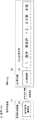
鉄道の駅構内等には行き先や発車時刻等を利用客へ知らせるために、表示器が設置されている。図1は、背景技術に係る表示システム101の構成を示す機能ブロック図である。表示システム101は駅のホーム上等に設置されるドットマトリックス方式のLED表示器150と、信号機器室内に設置される案内制御装置110とを備える。案内制御装置110にはLED表示器150の表示制御を行うと共に故障の監視を行う案内制御論理部120が備わる。LED表示器150は、ドットマトリックスLEDモジュールであるLED表示部170と、点灯制御を行うLEDコントローラーであるLED制御部160とを備える。LED表示部170には、例えば、次の列車の発車時間や行先等が表示される。
Indicators are installed in railway stations to inform users of destinations and departure times. FIG. 1 is a functional block diagram showing a configuration of a display system 101 according to the background art. The display system 101 includes a dot matrix
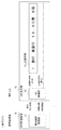
ここで、図2のタイミングチャートを参照して故障発生時の処理を正常時の処理とともに簡単に説明する。まず正常時の処理を説明する。案内制御論理部120はLED表示器150に対して表示指示を出力する。LED制御部160は、LED表示部170を構成する各LEDを点灯制御するための信号をLED表示指示として出力する。また、LED制御部160は、案内制御論理部120からの表示指示を適切に受信した旨を返信する。このようにして、案内制御装置110(案内制御論理部120)は、ドットマトリックスLEDモジュール(LED表示部70)に点灯信号を出力するためのコントローラー(LED制御部160)が何らかの原因で故障した場合の故障検知処理を行う。
Here, with reference to the timing chart of FIG. 2, the process at the time of occurrence of the failure will be briefly described together with the process at the normal time. First, normal processing will be described. The guidance
この種の故障検知技術として、例えば、表示ユニットの故障検出を行う際に、スルー設定信号により各表示ユニットをスルーモードとした上で、表示データに代えてチェックデータを提供し、各表示ユニットの監視ゲートの出力データの時系列合成の入力を受けるようにした技術がある(例えば特許文献1参照)。 As this type of failure detection technology, for example, when detecting a failure of a display unit, each display unit is set to a through mode by a through setting signal, and check data is provided instead of the display data. There is a technique that receives an input of time series synthesis of output data of a monitoring gate (see, for example, Patent Document 1).
ところで、図2の故障時の処理に示すように、LED表示部170において故障が発生し一部が表示されないような場合、案内制御装置110(案内制御論理部120)ではその把握ができないという課題があった。つまり、ドットマトリックスLEDモジュール自体に故障が発生した場合、信号機器室では把握が難しく、実際に目視でLED表示部170の表示を確認することで故障発生を認知していた。このため、対策の技術が必要とされていた。 By the way, as shown in the process at the time of failure in FIG. 2, when a failure occurs in the LED display unit 170 and a part is not displayed, the guidance control device 110 (guidance control logic unit 120) cannot grasp it. was there. That is, when a failure occurs in the dot matrix LED module itself, it is difficult to grasp in the signal equipment room, and the occurrence of the failure is recognized by actually checking the display on the LED display unit 170 visually. For this reason, countermeasure technology was required.
特許文献1に開示の技術では、1文字単位(またはモジュール単位)で故障検知を行うための仕組み(監視中信号、監視データの送出)が必要であり、構成や処理が複雑になる傾向のため、別の技術が求められていた。
The technique disclosed in
本発明はこのような状況に鑑みてなされたものであり、上記課題を解決できる技術を提供することを目的とする。 This invention is made | formed in view of such a condition, and it aims at providing the technique which can solve the said subject.
本発明の表示システム1は、ドットマトリックス方式の表示素子群及び前記表示素子のコントローラーを備える表示器と、前記表示器の点灯制御を行う制御論理部と、を有し、前記表示器は、前記コントローラーから前記表示素子群に出力した信号が前記コントローラーに返信する構成を有し、前記コントローラーは、表示素子群に対して出力した信号と返信された信号とを比較し前記表示素子群の故障発生の有無を判断する。
前記ドットマトリックス方式の表示素子群は、マトリックス状に表示素子を配置したモジュールを複数接続されて構成されており、前記表示素子群を点灯させるための点灯信号が、前記モジュールを全て経由して前記コントローラーに返信されてもよい。
The
The dot matrix type display element group is configured by connecting a plurality of modules in which display elements are arranged in a matrix, and a lighting signal for lighting the display element group passes through all the modules. It may be returned to the controller.
本発明は、ドットマトリックス方式の表示器の故障の発生の検出効率を向上させることができる。 The present invention can improve the detection efficiency of the occurrence of a failure in a dot matrix type display.
以下、本発明を実施するための形態(以下、「実施形態」という)を、図面を参照して説明する。 Hereinafter, modes for carrying out the present invention (hereinafter referred to as “embodiments”) will be described with reference to the drawings.
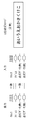
図3は本実施形態に係る表示システム1の概略構成を示す機能ブロック図である。表示システム1は、LED表示器50とそれに表示すべき情報(表示指示情報)を出力する案内制御装置10とを備える。
FIG. 3 is a functional block diagram showing a schematic configuration of the
案内制御装置10は、LED表示器50の表示制御を行うと共に故障の監視を行う案内制御論理部20を備える。つまり、案内制御論理部20は、LED表示器50に表示すべき情報(表示指示情報)をLED表示器50のLED制御部60に出力する。
The
LED表示器50は、ドットマトリックスLEDモジュールであるLED表示部70と、その点灯制御を行うLEDコントローラーであるLED制御部60とを備える。
The
LED表示部70は、赤と緑のLED素子をマトリックス状に備える。LED制御部60は、案内制御論理部20から取得した表示指示情報をもとに、LED表示部70を構成する複数のLED素子に設定すべき表示データを生成し、LED表示指示(行き)として出力するとともに、使用後の表示データをLED表示指示(帰り)として取得する。さらに、LED制御部60は、LED表示指示(行き)とLED表示指示(帰り)とを比較して、LED表示部70に故障が発生しているか否かを監視し、故障が発生していると判断すると、その旨を案内制御論理部20に通知する。LED制御部60自体に故障が発生している場合は、その旨を故障情報1として、LED表示部70に故障が発生している場合は、その旨を故障情報2として出力する。なお、故障情報1は、案内制御論理部20からの表示指示を適切に受信した旨の返信信号であってもよく、その条件であれば、所定期間内に返信されない場合、案内制御論理部20は故障発生認識する。
The
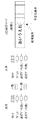
図4はLED表示器50の概略構成を示す機能ブロック図である。ここでは、LED制御部60とLED表示部70との間の信号送受信に着目した構成を示しており、案内制御論理部20とのデータ送受信機能及びデータ変換機能等については、公知のコントローラーと同様であり説明は省略する。
FIG. 4 is a functional block diagram showing a schematic configuration of the
LED制御部60は、LED表示部70とのデータ送受信機能として出力部61及び入力部62を備える。出力部61は、LED表示指示(行き)として、クロック信号、アドレス信号、点灯データ(赤)、点灯データ(緑)をLED表示部70に出力する。また、入力部62は、LED表示部70で使用されて帰還したクロック信号、アドレス信号、点灯データ(赤)、点灯データ(緑)をLED表示指示(帰り)として取得する。
The
LED表示部70は、第1〜第6のLEDモジュール70a〜70fを一列に並べて配置されている。第1〜第6のLEDモジュール70a〜70fは同一の構成となっている。図示では、第1のLEDモジュール70aについて内部構造を示し、他のモジュールの詳細は省略している。
The
第1のLEDモジュール70aは、赤と緑のLED素子がドットマトリックス状に配置されたLEDパネル71と、LED制御部60とのインターフェイスである入力IF72及び出力IF73と、タイミングコントローラ74、赤の点灯データを赤のLED素子に設定するレジストリ(赤)75及びドライバ(赤)76と、緑の点灯データを緑のLED素子に設定するレジストリ(緑)77及びドライバ(緑)78と、を備える。
The
これらの構成で公知の構成と異なる点は、上述の様に設定に使用された信号がLED表示器50に帰還する点にある。
These configurations are different from the known configurations in that the signals used for setting as described above are fed back to the
即ち、第1のLEDモジュール70aのレジストリ(赤)75に取り込まれた点灯データ(赤)は、出力IF73を介して第2のLEDモジュール70bに出力される。第2のLEDモジュール70bは、入力IF72を介して第1のLEDモジュール70aのレジストリ(赤)75から送られた点灯データ(赤)を、自身の点灯データ(赤)75に取り込み、第1のLEDモジュール70aと同様に、次のモジュールである第3のLEDモジュール70cに出力する。以降、各順次同様の動作・処理がなされ、最後の第6のLEDモジュール70fのレジストリ(赤)75に取り込まれた点灯データ(赤)は、出力IF73を介して、入力部62に帰還する。同様に、第1のLEDモジュール70aのレジストリ(緑)77に取り込まれた点灯データ(緑)は、順次第2〜第6のLEDモジュール70b〜70fに送られ、最終的には入力部62に帰還する。なお、クロック信号及びアドレス信号は、第1〜第6のLEDモジュール70a〜70fのそれぞれのタイミングコントローラ74に分岐した経路で設定される。
That is, the lighting data (red) taken into the registry (red) 75 of the
図5は、LED表示器50が正常時のLED制御部60の入出力信号とLED表示部70の表示イメージを示す図である。ここでは図示のように、正常時にはLED表示部70に「あいうえおかきくけこ」と表示される例を示している。
FIG. 5 is a diagram illustrating input / output signals of the
図6及び図7は、LED表示器50が故障時のLED制御部60の入出力信号とLED表示部70の表示イメージを示す図である。
6 and 7 are diagrams illustrating input / output signals of the
図6の例では、出力部61から出力された点灯データ(赤)及び(緑)と入力部62に入力された点灯データ(赤)及び(緑)が異なる状態になっている。その結果、LED表示部70の後半の「かきくけこ」の部分が不定となって表示されている。LED制御部60は、この状態を検知すると、案内制御論理部20にその旨を通知する。一般には、LED基板に実装されるレジストリ(赤)(緑)75、77及びドライバ(赤)(緑)76、78等の部品に故障が発生している。
In the example of FIG. 6, the lighting data (red) and (green) output from the
図7の例では、図6と同様に出力部61から出力された点灯データ(赤)及び(緑)と入力部62に入力された点灯データ(赤)及び(緑)が異なる状態になっており、更に、クロック信号又はアドレス信号が異なる状態になっている。その結果、LED表示部70の後半の「かきくけこ」の部分が不定となって表示されたり無灯状態で表示される。LED制御部60は、この状態を検知すると、案内制御論理部20にその旨を通知する。一般には、LED基板に実装されるレジストリ(赤)(緑)75、77及びドライバ(赤)(緑)76、78等の部品に故障が発生している。
In the example of FIG. 7, the lighting data (red) and (green) output from the
図8は、表示システム1における動作処理を示すチャート図であり、正常時と故障時とを比較できるように示している。まず、正常時は、案内制御論理部20からLED制御部60に表示指示が送信される。LED制御部60は、その表示指示に基づいてLED表示部70に対してLED表示指示(行き)を出力する。上述の様に、第1〜第6のLEDモジュール70a〜70fを経由して、LED表示指示(帰り)がLED制御部60に帰還する。
FIG. 8 is a chart showing an operation process in the
LED制御部60は、LED表示指示(行き)とLED表示指示(帰り)を照合比較して、適正(通常は同一)であれば、案内制御論理部20に「照合OK」を通知する。個々で、LED表示部70(第1〜第6のLEDモジュール70a〜70f)に故障が発生していれば、LED表示指示(行き)とLED表示指示(帰り)が不一致となったり、LED表示指示(帰り)が一定期間内に帰還しない。その場合には、LED制御部60は案内制御論理部20に「照合NG」を出力する。案内制御論理部20は、「照合NG」の場合、管理者等に対して「故障発生」を報知する。
The
以上、本実施形態によると、LED制御部60は、LED表示部70に出力したLED表示指示(行き)を、LED表示部70の使用後にLED表示指示(帰り)として取得し、LED表示指示(行き)とLED表示指示(帰り)を比較するので、LED表示部70を直接目視して確認しなくとも、故障発生を検出することができる。その結果、LED表示部70の故障発見を早期にできる。
As described above, according to the present embodiment, the
本方式は通常の表示データ自体の照合を行うことで、故障検知を行うための仕組みを別途必要とせず、表示段単位で故障検知が可能となる。 In this method, normal display data itself is collated, so that a separate mechanism for performing failure detection is not required, and failure detection can be performed in units of display stages.
以上、本発明を実施形態をもとに説明した。この実施形態は例示であり、それらの各構成要素及びその組合せにいろいろな変形例が可能なこと、またそうした変形例も本発明の範囲にあることは当業者に理解されるところである。例えば、上記の実施形態では、LED表示部70は、赤と緑の2色のLED素子をマトリックス状に備える構成を例示したが、これに限る趣旨ではなく、1色や3色以上のLED素子を備える構成、さらには、いわゆるフルカラーの表示ディバイスに対しても適用することができる。また、本実施形態の表示システム1は、鉄道の駅構内に設置される構成に限らず、例えば、デジタル・サイネージ(電子看板)として使用される表示装置のように、管理者等が常時画面を直接視聴しないようなシステムにおいて効果的に適用することができる。
The present invention has been described based on the embodiments. This embodiment is an exemplification, and it is understood by those skilled in the art that various modifications can be made to each of those components and combinations thereof, and such modifications are also within the scope of the present invention. For example, in the above-described embodiment, the
1 表示システム
10 案内制御装置
20 案内制御論理部
50 LED表示器
60 LED制御部
61 出力部
62 入力部
70 LED表示部
71 LEDパネル
72 入力IF
73 出力IF
74 タイミングコントローラ
75、77 レジストリ
76、78 ドライバ
70a〜70f 第1〜第6のLEDモジュール
DESCRIPTION OF
73 Output IF
74
Claims (2)
前記表示器の点灯制御を行う制御論理部と、を有し、
前記表示器は、前記コントローラーから前記表示素子群に出力した信号が前記コントローラーに返信する構成を有し、
前記コントローラーは、表示素子群に対して出力した信号と返信された信号とを比較し前記表示素子群の故障発生の有無を判断する
ことを特徴とする表示システム。 A display device comprising a dot matrix type display element group and a controller of the display element group;
A control logic unit that performs lighting control of the display,
The display has a configuration in which a signal output from the controller to the display element group is returned to the controller,
The display system, wherein the controller compares a signal output to the display element group and a returned signal to determine whether or not a failure has occurred in the display element group.
Priority Applications (1)
| Application Number | Priority Date | Filing Date | Title |
|---|---|---|---|
| JP2014079321A JP2015200780A (en) | 2014-04-08 | 2014-04-08 | display system |
Applications Claiming Priority (1)
| Application Number | Priority Date | Filing Date | Title |
|---|---|---|---|
| JP2014079321A JP2015200780A (en) | 2014-04-08 | 2014-04-08 | display system |
Publications (1)
| Publication Number | Publication Date |
|---|---|
| JP2015200780A true JP2015200780A (en) | 2015-11-12 |
Family
ID=54552070
Family Applications (1)
| Application Number | Title | Priority Date | Filing Date |
|---|---|---|---|
| JP2014079321A Pending JP2015200780A (en) | 2014-04-08 | 2014-04-08 | display system |
Country Status (1)
| Country | Link |
|---|---|
| JP (1) | JP2015200780A (en) |
Cited By (1)
| Publication number | Priority date | Publication date | Assignee | Title |
|---|---|---|---|---|
| CN113765941A (en) * | 2020-05-29 | 2021-12-07 | 西安诺瓦星云科技股份有限公司 | LED display screen controller, LED display screen control system and service data processing method |
Citations (7)
| Publication number | Priority date | Publication date | Assignee | Title |
|---|---|---|---|---|
| JPH0749666A (en) * | 1993-08-06 | 1995-02-21 | De-Shisu:Kk | Display unit |
| JPH07146663A (en) * | 1993-09-30 | 1995-06-06 | Toshiba Lighting & Technol Corp | Display controlling and monitoring device |
| JPH07146664A (en) * | 1993-09-30 | 1995-06-06 | Toshiba Lighting & Technol Corp | Display controlling and monitoring device |
| JPH07199851A (en) * | 1993-12-29 | 1995-08-04 | De-Shisu:Kk | Information display device |
| JP2002062841A (en) * | 2000-08-18 | 2002-02-28 | Nagoya Electric Works Co Ltd | Display method at the time of detecting failure in information display device |
| JP2002091372A (en) * | 2000-09-20 | 2002-03-27 | Nagoya Electric Works Co Ltd | Display method for information display device when failure is detected |
| JP2003167553A (en) * | 2001-11-30 | 2003-06-13 | Okaya Electric Ind Co Ltd | Display section abnormality detecting method |
-
2014
- 2014-04-08 JP JP2014079321A patent/JP2015200780A/en active Pending
Patent Citations (7)
| Publication number | Priority date | Publication date | Assignee | Title |
|---|---|---|---|---|
| JPH0749666A (en) * | 1993-08-06 | 1995-02-21 | De-Shisu:Kk | Display unit |
| JPH07146663A (en) * | 1993-09-30 | 1995-06-06 | Toshiba Lighting & Technol Corp | Display controlling and monitoring device |
| JPH07146664A (en) * | 1993-09-30 | 1995-06-06 | Toshiba Lighting & Technol Corp | Display controlling and monitoring device |
| JPH07199851A (en) * | 1993-12-29 | 1995-08-04 | De-Shisu:Kk | Information display device |
| JP2002062841A (en) * | 2000-08-18 | 2002-02-28 | Nagoya Electric Works Co Ltd | Display method at the time of detecting failure in information display device |
| JP2002091372A (en) * | 2000-09-20 | 2002-03-27 | Nagoya Electric Works Co Ltd | Display method for information display device when failure is detected |
| JP2003167553A (en) * | 2001-11-30 | 2003-06-13 | Okaya Electric Ind Co Ltd | Display section abnormality detecting method |
Cited By (1)
| Publication number | Priority date | Publication date | Assignee | Title |
|---|---|---|---|---|
| CN113765941A (en) * | 2020-05-29 | 2021-12-07 | 西安诺瓦星云科技股份有限公司 | LED display screen controller, LED display screen control system and service data processing method |
Similar Documents
| Publication | Publication Date | Title |
|---|---|---|
| CN106910447B (en) | Touch display panel, touch display device and display exception handling method | |
| JP5064197B2 (en) | Photoelectric sensor | |
| JP2008216334A (en) | Detecting method and detecting device for screen display fault | |
| JP2000324145A (en) | Network diagnostic device, network diagnostic method and network system | |
| JP2009058685A (en) | Panel display device, and method for detecting abnormality in panel | |
| CN106656575B (en) | A kind of method for diagnosing faults suitable for pilot protection multiplex channel | |
| JP2015200780A (en) | display system | |
| TW201621660A (en) | Hard disk drive operating status detection system | |
| KR102346865B1 (en) | Led module signal duplexing apparatus | |
| KR101668805B1 (en) | Display operation state monitoring system of smartboard | |
| JP4953859B2 (en) | Multi-optical axis photoelectric sensor system, multi-optical axis photoelectric sensor, abnormality identification device, abnormality identification method, and storage medium | |
| KR101641316B1 (en) | Display operation state monitoring system of smartboard | |
| JP2009104351A (en) | Connection state decision system | |
| JP2008275964A (en) | Video display device | |
| KR101511110B1 (en) | Method for Performance Monitoring LED System | |
| JP2016191771A5 (en) | ||
| JP2008096571A (en) | Dual-screen guidance display device, method, program and storage medium | |
| JP5445785B2 (en) | Course display device and control method thereof | |
| KR200445632Y1 (en) | LCD Pannel Test JIG | |
| JP2003248456A (en) | Plasma display panel driving module | |
| JP5860659B2 (en) | Train operation management system | |
| JP2005098901A (en) | Tft array inspection device | |
| JP3996840B2 (en) | Control system | |
| JP2006335150A (en) | On-vehicle electronic control system, failure diagnosing method thereof, and on-vehicle electronic control device | |
| JP2017156405A (en) | Display device |
Legal Events
| Date | Code | Title | Description |
|---|---|---|---|
| A621 | Written request for application examination |
Free format text: JAPANESE INTERMEDIATE CODE: A621 Effective date: 20160722 |
|
| A977 | Report on retrieval |
Free format text: JAPANESE INTERMEDIATE CODE: A971007 Effective date: 20170424 |
|
| A131 | Notification of reasons for refusal |
Free format text: JAPANESE INTERMEDIATE CODE: A131 Effective date: 20170516 |
|
| A02 | Decision of refusal |
Free format text: JAPANESE INTERMEDIATE CODE: A02 Effective date: 20171121 |