JP2015200105A - precast structure - Google Patents
precast structure Download PDFInfo
- Publication number
- JP2015200105A JP2015200105A JP2014079405A JP2014079405A JP2015200105A JP 2015200105 A JP2015200105 A JP 2015200105A JP 2014079405 A JP2014079405 A JP 2014079405A JP 2014079405 A JP2014079405 A JP 2014079405A JP 2015200105 A JP2015200105 A JP 2015200105A
- Authority
- JP
- Japan
- Prior art keywords
- precast structure
- sealing material
- precast
- filler
- installation surface
- Prior art date
- Legal status (The legal status is an assumption and is not a legal conclusion. Google has not performed a legal analysis and makes no representation as to the accuracy of the status listed.)
- Granted
Links
- 238000009434 installation Methods 0.000 claims abstract description 43
- 239000000945 filler Substances 0.000 claims abstract description 29
- 239000003566 sealing material Substances 0.000 claims description 59
- 230000007547 defect Effects 0.000 claims description 8
- 239000000565 sealant Substances 0.000 claims 1
- 239000000463 material Substances 0.000 abstract description 13
- 238000007796 conventional method Methods 0.000 abstract description 2
- 125000006850 spacer group Chemical group 0.000 description 19
- 238000000034 method Methods 0.000 description 17
- 239000011440 grout Substances 0.000 description 7
- 230000000694 effects Effects 0.000 description 5
- 230000006835 compression Effects 0.000 description 4
- 238000007906 compression Methods 0.000 description 4
- 239000004567 concrete Substances 0.000 description 4
- 238000010276 construction Methods 0.000 description 4
- 238000007789 sealing Methods 0.000 description 4
- 229910000831 Steel Inorganic materials 0.000 description 2
- 239000010959 steel Substances 0.000 description 2
- 230000015572 biosynthetic process Effects 0.000 description 1
- 230000002950 deficient Effects 0.000 description 1
- 238000012217 deletion Methods 0.000 description 1
- 230000037430 deletion Effects 0.000 description 1
- 238000002347 injection Methods 0.000 description 1
- 239000007924 injection Substances 0.000 description 1
- 238000004519 manufacturing process Methods 0.000 description 1
- 239000004570 mortar (masonry) Substances 0.000 description 1
- 230000002265 prevention Effects 0.000 description 1
- 239000011150 reinforced concrete Substances 0.000 description 1
- 239000004575 stone Substances 0.000 description 1
- 230000001629 suppression Effects 0.000 description 1
- 239000002699 waste material Substances 0.000 description 1
Images


Abstract
Description
本発明は、プレキャスト構造物を所定の箇所に設置する際に、該プレキャスト構造物と設置面との間に生じる間隙へと充填材を注入する際に、該充填材の漏れを防止するための構造を設けたプレキャスト構造物に関する。 The present invention is to prevent leakage of the filler when injecting the filler into the gap formed between the precast structure and the installation surface when the precast structure is installed at a predetermined location. The present invention relates to a precast structure provided with a structure.
ボックスカルバートなどのプレキャスト構造物の設置方法には、施工条件に応じて、例えば以下の2種類がある。
(1)均しコンクリートや基礎砕石などの設置面に、直接プレキャスト構造物を設置する方法。
(2)下記の特許文献1に記載されるような横引き工法によってプレキャスト構造物を運搬したのち、前記設置面とプレキャスト構造物との間に生じる間隙に、グラウトなどの充填材を注入して安定化する方法。
There are, for example, the following two types of installation methods for precast structures such as box culverts, depending on the construction conditions.
(1) A method of directly installing a precast structure on an installation surface such as leveled concrete or foundation crushed stone.
(2) After transporting the precast structure by a horizontal pulling method as described in Patent Document 1 below, a filler such as grout is injected into the gap formed between the installation surface and the precast structure. How to stabilize.
前記(2)の方法においてグラウト止めを行う方法としては、プレキャスト構造物を所定の位置に設置した後、該プレキャスト構造物の外側から、人力によって、モルタルやウエスを用いて前記隙間を間詰する手順が一般的である。 In the method (2), the grout is stopped by placing the precast structure in a predetermined position and then filling the gap with mortar or waste from the outside of the precast structure by human power. The procedure is general.
しかし、前記した従来のグラウト止めの方法の場合、プレキャスト構造物の側面と土留壁とが接近している現場の際に、プレキャスト構造物の設置後には、もはやグラウト止めを施したい箇所に人が立ち入りできず、グラウト止めができない問題があった。 However, in the case of the conventional grouting method described above, when the precast structure is close to the side wall and the retaining wall, after the precast structure is installed, a person is no longer in the place where grouting is to be applied. There was a problem that the grout could not be stopped.
よって、本願発明は、従来の方法と比較して、現場条件に制約を受けることなく、充填材の漏れを防止することが可能なプレキャスト構造物を提供することを目的の一つとする。 Therefore, it is an object of the present invention to provide a precast structure capable of preventing the filler from leaking without being restricted by on-site conditions as compared with the conventional method.
上記課題を解決すべくなされた本願の第1発明は、プレキャスト構造物を設置する際に、該プレキャスト構造物と設置面の間隙内に注入する充填材の漏れを防止するための、プレキャスト構造物であって、前記プレキャスト構造物の下隅部に、シール材を設けたことを特徴とするものである。
本願の第2発明は、前記第1発明において、前記下隅部に形成した欠損部にシール材を設けたことを特徴とするものである。
本願の第3発明は、前記第1発明または第2発明において、前記プレキャスト構造物に前記シール材を埋設して形成したことを特徴とするものである。
The first invention of the present application to solve the above problems is a precast structure for preventing leakage of a filler injected into a gap between the precast structure and the installation surface when the precast structure is installed. And the sealing material was provided in the lower corner part of the said precast structure, It is characterized by the above-mentioned.
A second invention of the present application is characterized in that, in the first invention, a sealing material is provided in a defective portion formed in the lower corner portion.
A third invention of the present application is characterized in that, in the first invention or the second invention, the sealing material is embedded in the precast structure.
本願発明によれば、以下に記載する効果のうち、少なくとも何れか1つの効果を得ることができる。
(1)施工現場の条件に制約を受けない。
プレキャスト構造物を所定の場所に設置した時点で、グラウト止めが施された態様とすることができる。よって、プレキャスト構造物の設置後にはプレキャスト構造物の周囲に人が立ち入れないような狭小な現場であったとしても、充填材の充填作業を精度良く実施することができる。
(2)シール材の圧縮量の確保と、充填材の充填量の抑制の両立が可能。
プレキャスト構造物の下隅部にシール材を配置する場合、プレキャスト構造物と設置面との間の間隙の高さ増につながり、充填材の充填量が増えてしまう恐れがあるが、前記プレキャスト構造物の下隅部に形成した欠損部にシール材を設けることで、プレキャスト構造物と設置面との間の距離は必要以上に拡張することなく、シール材の高さ(すなわち、シール材の圧縮量)を一定以上に確保することができる。
(3)シール材の捲れや捩れの防止。
例えば、前記プレキャスト構造物の下隅部の側面側に前記シール材を配置した場合には、プレキャスト構造物の自重により、シール材がプレキャスト構造物から捲れたり捩れたりするよう作用する危険性がある。しかし、前記シール材の一部を、前記プレキャスト構造物に埋設しておけば、シール材がより強固にプレキャスト構造物に結合され、前記した危険性を予め抑制することができる。
According to the present invention, at least one of the effects described below can be obtained.
(1) There are no restrictions on the conditions at the construction site.
When the precast structure is installed at a predetermined place, it is possible to adopt a mode in which the grout is stopped. Therefore, even if it is a narrow field where a person cannot enter around the precast structure after the precast structure is installed, the filling work of the filler can be performed with high accuracy.
(2) It is possible to ensure both the compression amount of the sealing material and the suppression of the filling amount of the filler.
When the sealing material is disposed at the lower corner of the precast structure, the gap between the precast structure and the installation surface may increase, and the filling amount of the filler may increase. By providing the sealing material at the chipped part formed in the lower corner, the distance between the precast structure and the installation surface does not extend more than necessary, and the height of the sealing material (ie, the amount of compression of the sealing material) Can be secured above a certain level.
(3) Prevention of twisting and twisting of the sealing material.
For example, when the sealing material is disposed on the side surface of the lower corner portion of the precast structure, there is a risk that the sealing material may be twisted or twisted from the precast structure due to the weight of the precast structure. However, if a part of the sealing material is embedded in the precast structure, the sealing material is more firmly coupled to the precast structure, and the above-described danger can be suppressed in advance.
以下、図面を参照しながら本発明のプレキャスト構造物について詳細に説明する。 Hereinafter, the precast structure of the present invention will be described in detail with reference to the drawings.
<1>全体構成(図1)。
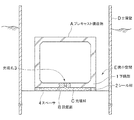
本発明のプレキャスト構造物は、ボックスカルバートや沈埋函などであり、設置面Bに設置するプレキャスト構造物Aと、該プレキャスト構造物Aの底面両側にある下隅部1に付設するシール材2と、該プレキャスト構造物Aと設置面Bとの間隙に充填する充填材Cと、を具備する。
本実施例では、プレキャスト構造物Aを、矩形断面を呈する鉄筋コンクリート製のボックスカルバートとした場合について説明する。
<1> Overall configuration (FIG. 1).
The precast structure of the present invention is a box culvert, a sink box, etc., a precast structure A installed on the installation surface B, and a sealing material 2 attached to the lower corners 1 on both sides of the bottom surface of the precast structure A, And a filler C that fills a gap between the precast structure A and the installation surface B.
A present Example demonstrates the case where the precast structure A is made into the box culvert made from a reinforced concrete which exhibits a rectangular cross section.
<2>プレキャスト構造物(図2)。
プレキャスト構造物Aは、クレーン移動や横引き工法などの周知の方法によって所定の箇所に配置されることを想定した構造物である。
プレキャスト構造物Aはボックスカルバートであり、矩形断面を有する筒状の構造体である。この構造体の底部と両側壁の境界である折曲箇所周辺を下隅部1と定義する。
そして、プレキャスト構造物Aの下面には、後述する充填材Cの充填作業のために、プレキャスト構造物Aの底面へと連通する充填孔3を設けている。
さらに、プレキャスト構造物Aの底面には、設置後のプレキャスト構造物Aの高さ合わせのためのスペーサ4を適宜設けている。
以下、各構成要素の詳細について説明する。
<2> Precast structure (FIG. 2).
The precast structure A is a structure that is assumed to be arranged at a predetermined location by a known method such as crane movement or horizontal pulling method.
The precast structure A is a box culvert, and is a cylindrical structure having a rectangular cross section. The lower corner 1 is defined as the periphery of the bent portion that is the boundary between the bottom of the structure and the side walls.
And in the lower surface of the precast structure A, the filling hole 3 connected to the bottom face of the precast structure A is provided for the filling operation | work of the filler C mentioned later.
Furthermore, a spacer 4 for adjusting the height of the precast structure A after installation is appropriately provided on the bottom surface of the precast structure A.
Details of each component will be described below.
<2.1>スペーサ(図2)。
スペーサ4は、プレキャスト構造物Aの高さ合わせに用いる部分である。
<2.1> Spacer (FIG. 2).
The spacer 4 is a part used for height adjustment of the precast structure A.
[素材]
スペーサ4の素材は、プレキャスト構造物Aの自重を支持するため、鋼材やコンクリート製品等の硬質材を用いるのが望ましい。
[Material]
The material of the spacer 4 is preferably a hard material such as a steel material or a concrete product in order to support the weight of the precast structure A.
[配置位置]
スペーサ4は、プレキャスト構造物Aの底面において、後述する運搬手段等が干渉しないような位置に設ける。本実施例では両側面付近にスペーサ4を設けている。ただし、プレキャスト構造物Aの全長に亘って設ける必要はなく、プレキャスト構造物の高さ合わせに必要な個所に必要な数だけ設ければよい。
[Positions]
The spacer 4 is provided on the bottom surface of the precast structure A at a position where a transportation means described later does not interfere. In this embodiment, spacers 4 are provided near both side surfaces. However, it is not necessary to provide the entire length of the precast structure A, and it is only necessary to provide the required number of places necessary for adjusting the height of the precast structure.
[形成態様]
スペーサ4は、別部材とするほか、プレキャスト構造物Aと一体形成した態様とすることができる。
なお、プレキャスト構造物Aにスペーサ4を設けない例については後の実施例で説明する。
[Formation]
The spacer 4 may be a separate member, or may be formed integrally with the precast structure A.
An example in which the spacer 4 is not provided in the precast structure A will be described in a later embodiment.
<2.2>シール材(図2)。
シール材2は、プレキャスト構造物Aの底面と設置面Bとの間隙から、充填材Cが漏れることを防止するための部材である。
<2.2> Seal material (FIG. 2).
The sealing material 2 is a member for preventing the filler C from leaking from the gap between the bottom surface of the precast structure A and the installation surface B.
[素材]
シール材2は、充填材Cに対する止水性と設置面Bの凹凸への追従性を有すれば、いずれの公知の部材を採用してもよい。
本実施例では、シール材2として軟質の継手用止水ゴムを採用する。継手用の止水ゴムは、追従性に加えて充填材Cの側圧に対する抵抗性も具備するため、特に有効である。
[Material]
The sealing material 2 may employ any known member as long as it has a water-stopping property with respect to the filler C and a follow-up property to the unevenness of the installation surface B.
In the present embodiment, a soft joint water-stopping rubber is employed as the sealing material 2. The water-stopping rubber for joints is particularly effective because it has resistance to the lateral pressure of the filler C in addition to followability.
[配置態様]
シール材2は、プレキャスト構造物Aの下隅部1の底面に、プレキャスト構造物Aの延伸方向(前後方向)に沿って隙間なく付設する。
本実施例では、プレキャスト構造物Aと、両側の土留壁Dとの間が何れも狭小空間Eであることを想定しており、両側の下隅部1の何れにもシール材2を設けているが、一方の下隅部1側で土留壁Dとの間が狭小でなければ従来のグラウト留めと併用する態様としてもよい。
シール材2のプレキャスト構造物Aへの付設には、ボルト止めや接着等の公知の手段を用いることができる。
[Arrangement mode]
The sealing material 2 is attached to the bottom surface of the lower corner portion 1 of the precast structure A with no gap along the extending direction (front-rear direction) of the precast structure A.
In the present embodiment, it is assumed that the space between the precast structure A and the retaining walls D on both sides is a narrow space E, and the sealing material 2 is provided in any of the lower corner portions 1 on both sides. However, it is good also as an aspect used together with the conventional grout fastening, if the space between the retaining wall D is not narrow on the one lower corner 1 side.
For attaching the sealing material 2 to the precast structure A, known means such as bolting or adhesion can be used.
シール材2の高さは、プレキャスト構造物Aの運搬時にシール材2の下部が設置面Bに干渉しない高さである。つまり、運搬時における、プレキャスト構造物Aの底面と設置面Bとの間隔より低い長さとする。
加えて、シール材2の高さは、プレキャスト構造物Aの底面からのスペーサ4の突出高より高い。スペーサ4の突出高より低いと、プレキャスト構造物Aの設置時、シール材2と設置面Bとの間に隙間が生じ、充填材Cのシール機能を発揮できないからである。
The height of the sealing material 2 is a height at which the lower portion of the sealing material 2 does not interfere with the installation surface B when the precast structure A is transported. That is, the length is shorter than the distance between the bottom surface of the precast structure A and the installation surface B during transportation.
In addition, the height of the sealing material 2 is higher than the protruding height of the spacer 4 from the bottom surface of the precast structure A. This is because when the height of the spacer 4 is lower than the protruding height, a gap is generated between the sealing material 2 and the installation surface B when the precast structure A is installed, and the sealing function of the filler C cannot be exhibited.
<3>充填材(図2)。
充填材Cは、プレキャスト構造物Aの底面と設置面との間の間隙を埋めるための材料である。
本実施例では、充填材Cとしてグラウトを採用する。
充填材Cはこれに限られず、いずれの公知の材料を採用してもよい。
<3> Filler (FIG. 2).
The filler C is a material for filling a gap between the bottom surface and the installation surface of the precast structure A.
In this embodiment, grout is used as the filler C.
The filler C is not limited to this, and any known material may be adopted.
<4>本発明の施工方法。
次に、図3A〜図3Cを参照しながら本発明のプレキャスト構造物の施工方法について説明する。
<4> The construction method of the present invention.
Next, the construction method of the precast structure of this invention is demonstrated, referring FIG. 3A-FIG. 3C.
<4.1>現場条件。
本実施例では、プレキャスト構造物の横引き工法において、均しコンクリートB1によって形成された設置面B上にプレキャスト構造物Aを設置する場合について説明する。
<4.1> Site conditions.
A present Example demonstrates the case where the precast structure A is installed on the installation surface B formed by the leveling concrete B1 in the horizontal drawing method of a precast structure.
<4.2>運搬方法。
横引き工法によるプレキャスト構造物Aの運搬方法には、各種の公知の方法を用いる。
例えばプレキャスト構造物の下方に、エアキャスターを設置し、エアキャスターに空気を圧送し、空気膜を利用してプレキャスト構造物を浮上させ、移動させる方法がある。
また、設置面に設けたレールに鋼球を敷き詰め、プレキャスト構造物の底面に付設したガイドと組み合わせて、レール上を滑走させる方法がある。
本実施例では、運搬手段Fとして、エアキャスターを用いる例について説明する。
<4.2> Transportation method.
Various well-known methods are used for the transport method of the precast structure A by the horizontal drawing method.
For example, there is a method in which an air caster is installed below the precast structure, air is pumped to the air caster, and the precast structure is lifted and moved using an air film.
In addition, there is a method in which a steel ball is spread on a rail provided on the installation surface and is slid on the rail in combination with a guide attached to the bottom surface of the precast structure.
In this embodiment, an example in which an air caster is used as the conveying means F will be described.
<4.3>プレキャスト構造物の運搬(図3A)。
まず、プレキャスト構造物Aを横引き工法にて設置場所まで運搬する。
次に、プレキャスト構造物Aを載置した運搬手段F(エアキャスター)に空気を注入することで、エアキャスターを膨張させ、プレキャスト構造物Aの底面を設置面から離間させる。
その後、エアキャスターから流出した空気で、エアキャスターの下部と設置面Bとの間に空気膜をつくり、エアキャスターを設置面Bから浮き上がらせる。
そして、エアキャスターを介して空気膜の上に載ったプレキャスト構造物Aを、人力やウインチを用いて設置場所へと移動させる。
ここで、シール2材は、持ち上げられたプレキャスト構造物Aの底面と設置面Bとの間隔より短いため、運搬中、シール材2の下面は設置面Bに干渉しない。
<4.3> Transportation of the precast structure (FIG. 3A).
First, the precast structure A is transported to the installation site by the horizontal pulling method.
Next, the air caster is expanded by injecting air into the transport means F (air caster) on which the precast structure A is placed, and the bottom surface of the precast structure A is separated from the installation surface.
Thereafter, an air film is formed between the lower portion of the air caster and the installation surface B with the air flowing out of the air caster, and the air caster is lifted from the installation surface B.
Then, the precast structure A placed on the air film via the air caster is moved to the installation location using human power or a winch.
Here, since the seal 2 material is shorter than the distance between the bottom surface of the lifted precast structure A and the installation surface B, the lower surface of the seal material 2 does not interfere with the installation surface B during transportation.
<4.4>プレキャスト構造物の設置(図3B)。
次に、プレキャスト構造物Aの設置位置を調整しながら、エアキャスターの空気を抜き、プレキャスト構造物Aを設置面Bへ設置する。
このとき、プレキャスト構造物Aの底面からスペーサ4が突出しているため、プレキャスト構造物Aはスペーサ4で接地する。
そして、プレキャスト構造物Aの底面と、設置面Bの間隙から、空気を抜いたエアキャスターを抜き出す。
エアキャスターを抜き出したあとのシール材2は、プレキャスト構造物の自重によってスペーサ4の高さまで圧縮され、プレキャスト構造物Aの底面と設置面Bとに密着する。これによって、プレキャスト構造物Aの底面と設置面Bとの間の間隙内の密閉効果が高まる。
<4.4> Installation of precast structure (FIG. 3B).
Next, while adjusting the installation position of the precast structure A, the air from the air caster is removed and the precast structure A is installed on the installation surface B.
At this time, since the spacer 4 protrudes from the bottom surface of the precast structure A, the precast structure A is grounded by the spacer 4.
And the air caster which extracted air is extracted from the bottom of the precast structure A and the installation surface B.
The sealing material 2 after extracting the air caster is compressed to the height of the spacer 4 by the weight of the precast structure and is in close contact with the bottom surface and the installation surface B of the precast structure A. Thereby, the sealing effect in the gap between the bottom surface of the precast structure A and the installation surface B is enhanced.
<4.5>充填材の注入(図3C)。
プレキャスト構造物Aが所定の位置に設置されたのち、プレキャスト構造物A内部の充填孔3から、プレキャスト構造物Aの底面と設置面Bとの間隙に充填材Cを注入する。
ここで、プレキャスト構造物Aの底面には、延伸方向に沿ってシール材2を延設してあるため、充填材Cがプレキャスト構造物Aの両側面から漏れることがない。
また、プレキャスト構造物Aの底面に予めシール材2を付設してあるため、プレキャスト構造物Aの設置後に、プレキャスト構造物Aの側面から充填止めの作業をする必要がない。
そのため、プレキャスト構造物Aの側面と土留壁Dとが接近している現場であっても、充填材Cの充填作業を精度良く実施することができる。
この充填材Cの硬化によって設置面Bの凹凸が埋まり、不陸が解消される。
<4.5> Filler injection (FIG. 3C).
After the precast structure A is installed at a predetermined position, the filler C is injected into the gap between the bottom surface of the precast structure A and the installation surface B from the filling hole 3 inside the precast structure A.
Here, since the sealing material 2 is extended along the extending direction on the bottom surface of the precast structure A, the filler C does not leak from both side surfaces of the precast structure A.
Moreover, since the sealing material 2 is previously attached to the bottom surface of the precast structure A, it is not necessary to perform a filling stop operation from the side surface of the precast structure A after the precast structure A is installed.
Therefore, the filling work of the filler C can be performed with high accuracy even at a site where the side surface of the precast structure A and the retaining wall D are close to each other.
The unevenness of the installation surface B is filled by the hardening of the filler C, and the unevenness is eliminated.
本実施例によれば、プレキャスト構造物を所定の場所に設置した時点で、グラウト留めが施された態様とすることができる。 According to the present Example, it can be set as the aspect by which grout fastening was given when the precast structure was installed in the predetermined place.
[シール材をプレキャスト構造物の側面に付設する例(図4)]
本発明の第2実施例について、図4を参照しながら説明する。
本実施例では、プレキャスト構造物Aの底面ではなく側面の下部にシール材2を付設する。
このとき、シール材2の下部を、プレキャスト構造物Aの底面より下方に突出させる。下方への突出長さは、スペーサ4の高さより長くする。
[Example of attaching a sealing material to the side of a precast structure (Fig. 4)]
A second embodiment of the present invention will be described with reference to FIG.
In the present embodiment, the sealing material 2 is attached to the lower portion of the side surface instead of the bottom surface of the precast structure A.
At this time, the lower part of the sealing material 2 is projected downward from the bottom surface of the precast structure A. The downward protruding length is longer than the height of the spacer 4.
本実施例によれば、プレキャスト構造物Aを設置した際に、シール材2の下部がスペーサ4の高さまで圧縮されるため、充填材Cの密封効果を高めることができる。 According to this embodiment, when the precast structure A is installed, the lower part of the sealing material 2 is compressed to the height of the spacer 4, so that the sealing effect of the filler C can be enhanced.
[シール材をプレキャスト構造物の底面と側面に付設する例(図5)]
本発明の第3実施例について、図5を参照しながら説明する。
本実施例では、プレキャスト構造物Aの底面だけでなく、側面の下部にもシール材を付設する。
このとき、シール材2の下部を、プレキャスト構造物Aの底面より下方に突出させる。下方への突出長さは、スペーサ4の高さより長く、かつ、底面に付設するシール材の高さ以上とする。なお、底面に付設するシール材2の高さと同じでもよい。
また、本発明は、底面のシール材2と側面のシール材2とを、別部材とせず一体構造としてもよい。
[Example of attaching sealing material to the bottom and side of the precast structure (Fig. 5)]
A third embodiment of the present invention will be described with reference to FIG.
In the present embodiment, the sealing material is attached not only to the bottom surface of the precast structure A but also to the lower portion of the side surface.
At this time, the lower part of the sealing material 2 is projected downward from the bottom surface of the precast structure A. The downward projecting length is longer than the height of the spacer 4 and not less than the height of the sealing material attached to the bottom surface. The height of the sealing material 2 attached to the bottom surface may be the same.
In the present invention, the bottom surface sealing material 2 and the side surface sealing material 2 may not be separate members but may be integrated.
本実施例によれば、底面に付設するシール材2と側面に付設するシール材2とによる、二重の密封効果を得ることができる。 According to the present Example, the double sealing effect by the sealing material 2 attached to a bottom face and the sealing material 2 attached to a side surface can be acquired.
[プレキャスト構造物に設けた欠損部にシール材を付設する例(図6A,6B)]
本発明の第4実施例について、図6A,6Bを参照しながら説明する。
[Example of attaching a sealing material to a defect provided in a precast structure (FIGS. 6A and 6B)]
A fourth embodiment of the present invention will be described with reference to FIGS. 6A and 6B.
設置面Bの不陸に対するシール材2の追従性を高めるには、シール材2の高さ(上下方向の長さ)をできる限り長くすることが好ましい。
これは、シール材2が長ければ、プレキャスト構造物Aの自重によるシール材2の圧縮量も大きくなるからである。
しかし、シール材2を長くしてしまうと、設置後のプレキャスト構造物と設置面との間の間隙も当然広くなってしまう。
In order to improve the followability of the sealing material 2 against the unevenness of the installation surface B, it is preferable to make the height (length in the vertical direction) of the sealing material 2 as long as possible.
This is because if the sealing material 2 is long, the amount of compression of the sealing material 2 due to the weight of the precast structure A increases.
However, if the sealing material 2 is lengthened, the gap between the precast structure after installation and the installation surface is naturally widened.
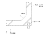
そこで、本実施例では、プレキャスト構造物Aの下隅部1に、段差状の欠損部11を設け、該欠損部11にシール材2を配置する構造とした。
より詳細に説明すると、本実施例に係るプレキャスト構造物は、該プレキャスト構造物Aの延伸方向全長に亘って下隅部1の一部を切り欠くように欠損部11を設けている。この欠損部11は、プレキャスト構造物Aの底面と略水平な天面を少なくとも設けるように設けることが好ましい。
そして、この欠損部11の天面にシール材2の頂部を付設するとともに、プレキャスト構造物Aの底面から、シール材2の下部を突出させる構造とした。
Therefore, in this embodiment, a step-shaped defect portion 11 is provided in the lower corner portion 1 of the precast structure A, and the sealing material 2 is disposed in the defect portion 11.
More specifically, the precast structure according to the present embodiment is provided with the defect portion 11 so as to cut out a part of the lower corner portion 1 over the entire length of the precast structure A in the extending direction. It is preferable that the defect portion 11 is provided so as to provide at least a top surface substantially horizontal to the bottom surface of the precast structure A.
And the top part of the sealing material 2 was attached to the top | upper surface of this defect | deletion part 11, and it was set as the structure which protrudes the lower part of the sealing material 2 from the bottom face of the precast structure A. As shown in FIG.
本実施例によれば、シール材2の圧縮量の確保による、設置面Bへの不陸追従性と、設置後のプレキャスト構造物Aと設置面Bとの間の間隙幅をなるべく狭くすることによる、充填材Cの充填量の削減効果を、同時に得ることができる。 According to the present embodiment, the non-land followability to the installation surface B by securing the compression amount of the sealing material 2 and the gap width between the precast structure A and the installation surface B after installation are reduced as much as possible. Thus, the effect of reducing the filling amount of the filler C can be obtained at the same time.
また、本実施例によれば、プレキャスト構造物Aにスペーサ4を設けない態様により、プレキャスト構造物Aの設置後に、該プレキャスト構造物Aの底面と、設置面Bのうち下隅部1の下方付近の設置面Bとの間にほぼ間隙が生じない場合などに、十分な高さのシール材2を配置するための方策としても有益である。 In addition, according to the present embodiment, the precast structure A is not provided with the spacer 4, so that after the precast structure A is installed, the bottom surface of the precast structure A and the vicinity of the lower corner 1 of the installation surface B This is also useful as a measure for disposing the sealing material 2 having a sufficiently high height when there is almost no gap between the mounting surface B and the mounting surface B.
[シール材をプレキャスト構造物に埋設する例]
本発明の第5実施例について、図7を参照しながら説明する。
本実施例では、プレキャスト構造物Aの下隅部1に予めシール材2を埋設した構造とする。
本構造は、プレキャスト構造物Aの製作時に予めシール材2を埋設した形としてもよいし、プレキャスト構造物Aの製作時に予め設けておいた溝部にシール材2の頂部を埋め込む形、その他公知の方法で実現することができる。
[Example of embedding seal material in precast structure]
A fifth embodiment of the present invention will be described with reference to FIG.
In this embodiment, the seal material 2 is embedded in the lower corner 1 of the precast structure A in advance.
This structure may have a shape in which the sealing material 2 is embedded in advance when the precast structure A is manufactured, a shape in which the top portion of the sealing material 2 is embedded in a groove portion that has been provided in advance in manufacturing the precast structure A, and other publicly known structures. Can be realized by the method.
本実施例によれば、シール材2がプレキャスト構造物Aにより強固に結合されるため、シール材2の捲れや捩れを防ぐことができる効果を奏する。また、シール材2に前記スペーサ4としての機能を兼用させることもできる。 According to this embodiment, since the sealing material 2 is firmly bonded by the precast structure A, the sealing material 2 can be prevented from being twisted or twisted. Further, the sealing material 2 can also function as the spacer 4.
A プレキャスト構造物
B 設置面
B1 均しコンクリート
C 充填材
D 土留壁
E 狭小空間
F 運搬手段
1 下隅部
11 欠損部
2 シール材
3 充填孔
4 スペーサ
A Precast structure B Installation surface B1 Leveling concrete C Filler D Retaining wall E Narrow space F Conveying means 1 Lower corner 11 Defect 2 Sealing material 3 Filling hole 4 Spacer
Claims (3)
前記プレキャスト構造物の下隅部に、シール材を設けたことを特徴とする、
プレキャスト構造物。 A precast structure for preventing leakage of a filler injected into a gap between the precast structure and an installation surface when the precast structure is installed,
In the lower corner of the precast structure, a sealing material is provided,
Precast structure.
Priority Applications (1)
| Application Number | Priority Date | Filing Date | Title |
|---|---|---|---|
| JP2014079405A JP6400934B2 (en) | 2014-04-08 | 2014-04-08 | Precast structure installation method |
Applications Claiming Priority (1)
| Application Number | Priority Date | Filing Date | Title |
|---|---|---|---|
| JP2014079405A JP6400934B2 (en) | 2014-04-08 | 2014-04-08 | Precast structure installation method |
Publications (2)
| Publication Number | Publication Date |
|---|---|
| JP2015200105A true JP2015200105A (en) | 2015-11-12 |
| JP6400934B2 JP6400934B2 (en) | 2018-10-03 |
Family
ID=54551627
Family Applications (1)
| Application Number | Title | Priority Date | Filing Date |
|---|---|---|---|
| JP2014079405A Active JP6400934B2 (en) | 2014-04-08 | 2014-04-08 | Precast structure installation method |
Country Status (1)
| Country | Link |
|---|---|
| JP (1) | JP6400934B2 (en) |
Cited By (2)
| Publication number | Priority date | Publication date | Assignee | Title |
|---|---|---|---|---|
| JP2018035530A (en) * | 2016-08-30 | 2018-03-08 | 積水化学工業株式会社 | Building foundation structure |
| JP2018035531A (en) * | 2016-08-30 | 2018-03-08 | 積水化学工業株式会社 | Building foundation structure |
Citations (10)
| Publication number | Priority date | Publication date | Assignee | Title |
|---|---|---|---|---|
| US4697955A (en) * | 1982-07-30 | 1987-10-06 | Le Clerco Pierre A L M G | Method of constructing reinforced concrete works such as underground galleries, road tunnels, et cetera; pre-fabricated contrete elements for constructing such works |
| JPS63171482U (en) * | 1987-04-28 | 1988-11-08 | ||
| JPS6417912A (en) * | 1987-07-14 | 1989-01-20 | Fuji Shoji | Construction work method of large concrete block |
| JPS6410551U (en) * | 1987-07-03 | 1989-01-20 | ||
| JPS6475742A (en) * | 1987-09-17 | 1989-03-22 | Fuji Shoji | Method of executing drainage channel |
| JPH02104821A (en) * | 1988-10-14 | 1990-04-17 | Misawa Homes Co Ltd | Basement of prefabricated type |
| JPH05263458A (en) * | 1992-03-16 | 1993-10-12 | Kensetsusho Hokurikuchihou Kensetsukyoku | Installation method for precast concrete member and its device |
| JPH07259062A (en) * | 1994-03-25 | 1995-10-09 | Chika Nakaya | Method and device for constructing bottom board of concrete product |
| JPH08144360A (en) * | 1994-11-25 | 1996-06-04 | Hokukon Kensetsu Kogyo Kk | Concrete block carrying device, concrete block carrying method using that device, and concrete block to be carried |
| JP2000110185A (en) * | 1998-10-06 | 2000-04-18 | Ohbayashi Corp | Construction method for underwater foundation |
-
2014
- 2014-04-08 JP JP2014079405A patent/JP6400934B2/en active Active
Patent Citations (10)
| Publication number | Priority date | Publication date | Assignee | Title |
|---|---|---|---|---|
| US4697955A (en) * | 1982-07-30 | 1987-10-06 | Le Clerco Pierre A L M G | Method of constructing reinforced concrete works such as underground galleries, road tunnels, et cetera; pre-fabricated contrete elements for constructing such works |
| JPS63171482U (en) * | 1987-04-28 | 1988-11-08 | ||
| JPS6410551U (en) * | 1987-07-03 | 1989-01-20 | ||
| JPS6417912A (en) * | 1987-07-14 | 1989-01-20 | Fuji Shoji | Construction work method of large concrete block |
| JPS6475742A (en) * | 1987-09-17 | 1989-03-22 | Fuji Shoji | Method of executing drainage channel |
| JPH02104821A (en) * | 1988-10-14 | 1990-04-17 | Misawa Homes Co Ltd | Basement of prefabricated type |
| JPH05263458A (en) * | 1992-03-16 | 1993-10-12 | Kensetsusho Hokurikuchihou Kensetsukyoku | Installation method for precast concrete member and its device |
| JPH07259062A (en) * | 1994-03-25 | 1995-10-09 | Chika Nakaya | Method and device for constructing bottom board of concrete product |
| JPH08144360A (en) * | 1994-11-25 | 1996-06-04 | Hokukon Kensetsu Kogyo Kk | Concrete block carrying device, concrete block carrying method using that device, and concrete block to be carried |
| JP2000110185A (en) * | 1998-10-06 | 2000-04-18 | Ohbayashi Corp | Construction method for underwater foundation |
Cited By (2)
| Publication number | Priority date | Publication date | Assignee | Title |
|---|---|---|---|---|
| JP2018035530A (en) * | 2016-08-30 | 2018-03-08 | 積水化学工業株式会社 | Building foundation structure |
| JP2018035531A (en) * | 2016-08-30 | 2018-03-08 | 積水化学工業株式会社 | Building foundation structure |
Also Published As
| Publication number | Publication date |
|---|---|
| JP6400934B2 (en) | 2018-10-03 |
Similar Documents
| Publication | Publication Date | Title |
|---|---|---|
| JP5576207B2 (en) | Installation foundation and its construction method | |
| CN107542115B (en) | Underground engineering waterproof structure and construction method thereof | |
| KR101433344B1 (en) | Method for constructing a culvet structure assembly | |
| JP6400934B2 (en) | Precast structure installation method | |
| JP6548455B2 (en) | Water stop structure of continuous wall | |
| JPWO2010073538A1 (en) | Steel sheet pile wall and its construction method | |
| CN210797919U (en) | Waterproof structure of wall deformation joint | |
| CN102720275B (en) | Flexible coiled material for deformation joint and construction method of flexible coiled material | |
| KR101593998B1 (en) | Expansion joint maintenance facility and using the repair method | |
| JP6933916B2 (en) | Embankment raising structure | |
| US20160010297A1 (en) | Pilaster repair device and method for repairing seawalls | |
| JP3905069B2 (en) | Dry work box and installation method | |
| KR20120009212A (en) | Box structure for shear bucking prevention that habe rotation function | |
| KR200375669Y1 (en) | Expansion joint equipment in jointing point of structure | |
| JP6154244B2 (en) | Block connecting hole joint device, biasing pressure contact member manufacturing method, block joint construction method and block connecting method | |
| KR20120134677A (en) | The precast concrete closed conduit that is reinforced by the shear connector and constructing method of it | |
| KR101136086B1 (en) | Sealnat injection water leakage interception way of structure | |
| JP2010095907A (en) | Reinforcing structure and reinforcing method for existing foundation | |
| JP2014201944A (en) | Floor slab unit and pavement structure using the same | |
| JP2014098239A (en) | Structure and method for repairing existing channel | |
| JP5458160B1 (en) | Stuffing method | |
| CN214994118U (en) | Post-cast strip water stopping structure | |
| JP6871723B2 (en) | How to build precast formwork and foundation structure | |
| JP6374736B2 (en) | Underground structure and construction method of underground structure | |
| JP2017066826A (en) | Joint method of concrete member and precast member |
Legal Events
| Date | Code | Title | Description |
|---|---|---|---|
| A621 | Written request for application examination |
Free format text: JAPANESE INTERMEDIATE CODE: A621 Effective date: 20170314 |
|
| A977 | Report on retrieval |
Free format text: JAPANESE INTERMEDIATE CODE: A971007 Effective date: 20180126 |
|
| A131 | Notification of reasons for refusal |
Free format text: JAPANESE INTERMEDIATE CODE: A131 Effective date: 20180130 |
|
| A521 | Request for written amendment filed |
Free format text: JAPANESE INTERMEDIATE CODE: A523 Effective date: 20180319 |
|
| A131 | Notification of reasons for refusal |
Free format text: JAPANESE INTERMEDIATE CODE: A131 Effective date: 20180612 |
|
| A521 | Request for written amendment filed |
Free format text: JAPANESE INTERMEDIATE CODE: A523 Effective date: 20180711 |
|
| TRDD | Decision of grant or rejection written | ||
| A01 | Written decision to grant a patent or to grant a registration (utility model) |
Free format text: JAPANESE INTERMEDIATE CODE: A01 Effective date: 20180904 |
|
| A61 | First payment of annual fees (during grant procedure) |
Free format text: JAPANESE INTERMEDIATE CODE: A61 Effective date: 20180906 |
|
| R150 | Certificate of patent or registration of utility model |
Ref document number: 6400934 Country of ref document: JP Free format text: JAPANESE INTERMEDIATE CODE: R150 |