JP2015199012A - Preform coating device, preform production method, and plastic bottle production method - Google Patents
Preform coating device, preform production method, and plastic bottle production method Download PDFInfo
- Publication number
- JP2015199012A JP2015199012A JP2014078114A JP2014078114A JP2015199012A JP 2015199012 A JP2015199012 A JP 2015199012A JP 2014078114 A JP2014078114 A JP 2014078114A JP 2014078114 A JP2014078114 A JP 2014078114A JP 2015199012 A JP2015199012 A JP 2015199012A
- Authority
- JP
- Japan
- Prior art keywords
- preform
- outer peripheral
- peripheral surface
- transfer roller
- coating
- Prior art date
- Legal status (The legal status is an assumption and is not a legal conclusion. Google has not performed a legal analysis and makes no representation as to the accuracy of the status listed.)
- Pending
Links
Images


Classifications
-
- B—PERFORMING OPERATIONS; TRANSPORTING
- B29—WORKING OF PLASTICS; WORKING OF SUBSTANCES IN A PLASTIC STATE IN GENERAL
- B29C—SHAPING OR JOINING OF PLASTICS; SHAPING OF MATERIAL IN A PLASTIC STATE, NOT OTHERWISE PROVIDED FOR; AFTER-TREATMENT OF THE SHAPED PRODUCTS, e.g. REPAIRING
- B29C49/00—Blow-moulding, i.e. blowing a preform or parison to a desired shape within a mould; Apparatus therefor
- B29C49/02—Combined blow-moulding and manufacture of the preform or the parison
- B29C49/06—Injection blow-moulding
-
- B—PERFORMING OPERATIONS; TRANSPORTING
- B05—SPRAYING OR ATOMISING IN GENERAL; APPLYING FLUENT MATERIALS TO SURFACES, IN GENERAL
- B05C—APPARATUS FOR APPLYING FLUENT MATERIALS TO SURFACES, IN GENERAL
- B05C1/00—Apparatus in which liquid or other fluent material is applied to the surface of the work by contact with a member carrying the liquid or other fluent material, e.g. a porous member loaded with a liquid to be applied as a coating
- B05C1/02—Apparatus in which liquid or other fluent material is applied to the surface of the work by contact with a member carrying the liquid or other fluent material, e.g. a porous member loaded with a liquid to be applied as a coating for applying liquid or other fluent material to separate articles
- B05C1/022—Apparatus in which liquid or other fluent material is applied to the surface of the work by contact with a member carrying the liquid or other fluent material, e.g. a porous member loaded with a liquid to be applied as a coating for applying liquid or other fluent material to separate articles to the outer surface of hollow articles
-
- B—PERFORMING OPERATIONS; TRANSPORTING
- B05—SPRAYING OR ATOMISING IN GENERAL; APPLYING FLUENT MATERIALS TO SURFACES, IN GENERAL
- B05D—PROCESSES FOR APPLYING FLUENT MATERIALS TO SURFACES, IN GENERAL
- B05D1/00—Processes for applying liquids or other fluent materials
- B05D1/28—Processes for applying liquids or other fluent materials performed by transfer from the surfaces of elements carrying the liquid or other fluent material, e.g. brushes, pads, rollers
-
- B—PERFORMING OPERATIONS; TRANSPORTING
- B05—SPRAYING OR ATOMISING IN GENERAL; APPLYING FLUENT MATERIALS TO SURFACES, IN GENERAL
- B05D—PROCESSES FOR APPLYING FLUENT MATERIALS TO SURFACES, IN GENERAL
- B05D3/00—Pretreatment of surfaces to which liquids or other fluent materials are to be applied; After-treatment of applied coatings, e.g. intermediate treating of an applied coating preparatory to subsequent applications of liquids or other fluent materials
- B05D3/007—After-treatment
-
- B—PERFORMING OPERATIONS; TRANSPORTING
- B05—SPRAYING OR ATOMISING IN GENERAL; APPLYING FLUENT MATERIALS TO SURFACES, IN GENERAL
- B05D—PROCESSES FOR APPLYING FLUENT MATERIALS TO SURFACES, IN GENERAL
- B05D7/00—Processes, other than flocking, specially adapted for applying liquids or other fluent materials to particular surfaces or for applying particular liquids or other fluent materials
- B05D7/22—Processes, other than flocking, specially adapted for applying liquids or other fluent materials to particular surfaces or for applying particular liquids or other fluent materials to internal surfaces, e.g. of tubes
- B05D7/227—Processes, other than flocking, specially adapted for applying liquids or other fluent materials to particular surfaces or for applying particular liquids or other fluent materials to internal surfaces, e.g. of tubes of containers, cans or the like
-
- B—PERFORMING OPERATIONS; TRANSPORTING
- B29—WORKING OF PLASTICS; WORKING OF SUBSTANCES IN A PLASTIC STATE IN GENERAL
- B29B—PREPARATION OR PRETREATMENT OF THE MATERIAL TO BE SHAPED; MAKING GRANULES OR PREFORMS; RECOVERY OF PLASTICS OR OTHER CONSTITUENTS OF WASTE MATERIAL CONTAINING PLASTICS
- B29B11/00—Making preforms
-
- B—PERFORMING OPERATIONS; TRANSPORTING
- B65—CONVEYING; PACKING; STORING; HANDLING THIN OR FILAMENTARY MATERIAL
- B65D—CONTAINERS FOR STORAGE OR TRANSPORT OF ARTICLES OR MATERIALS, e.g. BAGS, BARRELS, BOTTLES, BOXES, CANS, CARTONS, CRATES, DRUMS, JARS, TANKS, HOPPERS, FORWARDING CONTAINERS; ACCESSORIES, CLOSURES, OR FITTINGS THEREFOR; PACKAGING ELEMENTS; PACKAGES
- B65D23/00—Details of bottles or jars not otherwise provided for
- B65D23/08—Coverings or external coatings
- B65D23/0807—Coatings
-
- B—PERFORMING OPERATIONS; TRANSPORTING
- B05—SPRAYING OR ATOMISING IN GENERAL; APPLYING FLUENT MATERIALS TO SURFACES, IN GENERAL
- B05C—APPARATUS FOR APPLYING FLUENT MATERIALS TO SURFACES, IN GENERAL
- B05C1/00—Apparatus in which liquid or other fluent material is applied to the surface of the work by contact with a member carrying the liquid or other fluent material, e.g. a porous member loaded with a liquid to be applied as a coating
- B05C1/04—Apparatus in which liquid or other fluent material is applied to the surface of the work by contact with a member carrying the liquid or other fluent material, e.g. a porous member loaded with a liquid to be applied as a coating for applying liquid or other fluent material to work of indefinite length
- B05C1/08—Apparatus in which liquid or other fluent material is applied to the surface of the work by contact with a member carrying the liquid or other fluent material, e.g. a porous member loaded with a liquid to be applied as a coating for applying liquid or other fluent material to work of indefinite length using a roller or other rotating member which contacts the work along a generating line
- B05C1/0813—Apparatus in which liquid or other fluent material is applied to the surface of the work by contact with a member carrying the liquid or other fluent material, e.g. a porous member loaded with a liquid to be applied as a coating for applying liquid or other fluent material to work of indefinite length using a roller or other rotating member which contacts the work along a generating line characterised by means for supplying liquid or other fluent material to the roller
-
- B—PERFORMING OPERATIONS; TRANSPORTING
- B05—SPRAYING OR ATOMISING IN GENERAL; APPLYING FLUENT MATERIALS TO SURFACES, IN GENERAL
- B05D—PROCESSES FOR APPLYING FLUENT MATERIALS TO SURFACES, IN GENERAL
- B05D2201/00—Polymeric substrate or laminate
-
- B—PERFORMING OPERATIONS; TRANSPORTING
- B29—WORKING OF PLASTICS; WORKING OF SUBSTANCES IN A PLASTIC STATE IN GENERAL
- B29C—SHAPING OR JOINING OF PLASTICS; SHAPING OF MATERIAL IN A PLASTIC STATE, NOT OTHERWISE PROVIDED FOR; AFTER-TREATMENT OF THE SHAPED PRODUCTS, e.g. REPAIRING
- B29C49/00—Blow-moulding, i.e. blowing a preform or parison to a desired shape within a mould; Apparatus therefor
- B29C49/02—Combined blow-moulding and manufacture of the preform or the parison
- B29C2049/023—Combined blow-moulding and manufacture of the preform or the parison using inherent heat of the preform, i.e. 1 step blow moulding
-
- B—PERFORMING OPERATIONS; TRANSPORTING
- B29—WORKING OF PLASTICS; WORKING OF SUBSTANCES IN A PLASTIC STATE IN GENERAL
- B29C—SHAPING OR JOINING OF PLASTICS; SHAPING OF MATERIAL IN A PLASTIC STATE, NOT OTHERWISE PROVIDED FOR; AFTER-TREATMENT OF THE SHAPED PRODUCTS, e.g. REPAIRING
- B29C2949/00—Indexing scheme relating to blow-moulding
- B29C2949/30—Preforms or parisons made of several components
- B29C2949/3064—Preforms or parisons made of several components having at least one components being applied using techniques not covered by B29C2949/3032 - B29C2949/3062
- B29C2949/3074—Preforms or parisons made of several components having at least one components being applied using techniques not covered by B29C2949/3032 - B29C2949/3062 said at least one component obtained by coating
-
- B—PERFORMING OPERATIONS; TRANSPORTING
- B29—WORKING OF PLASTICS; WORKING OF SUBSTANCES IN A PLASTIC STATE IN GENERAL
- B29L—INDEXING SCHEME ASSOCIATED WITH SUBCLASS B29C, RELATING TO PARTICULAR ARTICLES
- B29L2009/00—Layered products
- B29L2009/005—Layered products coated
-
- B—PERFORMING OPERATIONS; TRANSPORTING
- B29—WORKING OF PLASTICS; WORKING OF SUBSTANCES IN A PLASTIC STATE IN GENERAL
- B29L—INDEXING SCHEME ASSOCIATED WITH SUBCLASS B29C, RELATING TO PARTICULAR ARTICLES
- B29L2031/00—Other particular articles
- B29L2031/712—Containers; Packaging elements or accessories, Packages
- B29L2031/7158—Bottles
Abstract
Description
本発明は、プラスチックボトル用のプリフォームをコーティング液でコーティングするためのプリフォームコーティング装置、プリフォームの製造方法、及びプラスチックボトルの製造方法に関する。 The present invention relates to a preform coating apparatus, a preform manufacturing method, and a plastic bottle manufacturing method for coating a preform for a plastic bottle with a coating liquid.
今日、ポリエチレンテレフタレート製のプラスチック容器(ペットボトル)等のプラスチックボトルが飲料又は食料を収容するのに広く使用されている。プラスチックボトルは、試験管状のプリフォームを延伸ブロー成形で膨らませることによって成形される。 Today, plastic bottles such as polyethylene terephthalate plastic containers (pet bottles) are widely used to contain beverages or food. The plastic bottle is formed by inflating a test tubular preform by stretch blow molding.
特許文献1に開示されるように、酸素及び二酸化炭素のようなガスがプラスチックボトルの内外に透過することを低減すべく、プリフォームの外周面にバリアコーティングを形成することが知られている。バリアコーティングの形成は、コーティング液をプリフォームの外周面に塗布し、プリフォームの外周面を乾燥させることによって行われる。
As disclosed in
しかしながら、コーティング液の塗布は、典型的には、図6に示されるように、プリフォームをコーティング液に鉛直方向に浸漬することによって行われる。この場合、プリフォームの外周面において、重力によってコーティング液の膜厚が鉛直方向下向きに向かって次第に厚くなる。 However, the coating solution is typically applied by immersing the preform in the vertical direction in the coating solution as shown in FIG. In this case, on the outer peripheral surface of the preform, the film thickness of the coating liquid gradually increases in the vertical direction due to gravity.
このため、ガスの透過を低減するバリア性能がプリフォームひいてはプラスチックボトルの外周面において不均一になる。また、膜厚が不均一な状態でコーティング液を完全に乾燥させようとすると、膜厚が薄い部分が過剰に加熱されて白化することがある。特に、プリフォームをコーティング液に鉛直方向に浸漬すると、プリフォームの底部にもコーティング液が塗布されるので、コーティング液の乾燥時間が長くなる。このため、膜厚が厚い底部のコーティング液を乾燥させようとすると、膜厚が薄いプリフォームの円筒状胴部が、過剰に加熱されることになり、白化する傾向にある。これらの白化したプリフォーム又はプラスチックボトルは、最終的な検査工程において不良品と見なされて使用不可能であることが多い。また、プラスチックボトルをブロー成型する際、プリフォームが白化していると、ブロー工程において延伸不良となり、所定の大きさのプラスチックボトルができなかったり、割れてしまったりすることがある。 For this reason, the barrier performance for reducing gas permeation becomes uneven on the outer periphery of the preform and thus the plastic bottle. Further, if the coating solution is to be completely dried in a state where the film thickness is not uniform, a portion having a small film thickness may be excessively heated and whitened. In particular, when the preform is immersed in the coating solution in the vertical direction, the coating solution is also applied to the bottom of the preform, so that the drying time of the coating solution becomes long. For this reason, if it is going to dry the coating liquid of the bottom part with a thick film thickness, the cylindrical trunk | drum of a preform with a thin film thickness will be heated excessively and tends to be whitened. These whitened preforms or plastic bottles are often considered defective in the final inspection process and cannot be used. Further, if the preform is whitened when blow-molding the plastic bottle, stretching may be poor in the blowing process, and a plastic bottle having a predetermined size may not be formed or may be broken.
そこで、本発明は、上記の問題点に鑑みてなされたものであって、プラスチックボトル用のプリフォームの外周面に塗布されるコーティング液の膜厚を薄く均一にすることで、プリフォーム又はプラスチックボトルの不良品の発生を低減することを目的とする。 Therefore, the present invention has been made in view of the above-described problems, and the preform or plastic is obtained by making the film thickness of the coating liquid applied to the outer peripheral surface of the preform for plastic bottle thin and uniform. The purpose is to reduce the occurrence of defective bottles.
本発明の第1態様では、中心軸回りに回転する円柱形状の転写ローラと、転写ローラの外周面にスロットからコーティング液を所定の厚みで塗布する塗布装置と、を備え、転写ローラの外周面がプリフォームの外周面に回転接触することによって、コーティング液が転写ローラの外周面からプリフォームの外周面に転写される、プリフォームコーティング装置が提供される。 According to a first aspect of the present invention, a cylindrical transfer roller that rotates about a central axis, and a coating device that applies a coating liquid from a slot to the outer peripheral surface of the transfer roller with a predetermined thickness are provided. A preform coating apparatus is provided in which the coating liquid is transferred from the outer peripheral surface of the transfer roller to the outer peripheral surface of the preform by rotationally contacting the outer peripheral surface of the preform.
本発明の第1態様では、塗布装置が、スロットが形成され且つ転写ローラの外周面にスロットからコーティング液を吐出するように構成されたダイコータであることが好ましい。 In the first aspect of the present invention, it is preferable that the coating device is a die coater in which a slot is formed and the coating liquid is discharged from the slot to the outer peripheral surface of the transfer roller.
本発明の第1態様では、プリフォームコーティング装置が、さらに、プリフォームを搬送する搬送装置を備え、プリフォームの搬送経路が、転写ローラの外周面に沿った略円弧状の経路を含むことが好ましい。 In the first aspect of the present invention, the preform coating apparatus further includes a transport device that transports the preform, and the preform transport path includes a substantially arc-shaped path along the outer peripheral surface of the transfer roller. preferable.
本発明の第1態様では、コーティング液が転写ローラの外周面からプリフォームの円筒状胴部のみに転写されることが好ましい。 In the first aspect of the present invention, the coating liquid is preferably transferred only from the outer peripheral surface of the transfer roller to the cylindrical body of the preform.
本発明の第1態様では、プリフォームコーティング装置が、さらに、プリフォームの外周面に転写されなかったコーティング液を転写ローラの外周面から掻き取るように構成されたスクレーパを備えることが好ましい。 In the first aspect of the present invention, it is preferable that the preform coating apparatus further includes a scraper configured to scrape the coating liquid that has not been transferred to the outer peripheral surface of the preform from the outer peripheral surface of the transfer roller.
本発明の第1態様では、プリフォームコーティング装置が、さらに、スクレーパで掻き取られたコーティング液を回収する液回収タンクと、回収されたコーティング液を脱泡する脱泡装置とを備えることが好ましい。 In the first aspect of the present invention, the preform coating apparatus preferably further includes a liquid recovery tank that recovers the coating liquid scraped by the scraper, and a defoaming apparatus that degass the recovered coating liquid. .
本発明の第2態様では、中心軸回りに回転する円柱形状の転写ローラの外周面に塗布装置でコーティング液を所定の厚みで塗布するステップと、プリフォームを転写ローラの外周面上に搬送し、転写ローラの外周面からプリフォームの外周面にコーティング液を転写するステップと、プリフォームの外周面を乾燥させるステップとを含む、プリフォームの製造方法が提供される。 In the second aspect of the present invention, the coating liquid is applied to the outer peripheral surface of the cylindrical transfer roller rotating about the central axis with a coating device at a predetermined thickness, and the preform is conveyed onto the outer peripheral surface of the transfer roller. There is provided a method for manufacturing a preform, including the steps of transferring a coating liquid from the outer peripheral surface of the transfer roller to the outer peripheral surface of the preform, and drying the outer peripheral surface of the preform.
本発明の第2態様では、コーティング液が転写ローラの外周面からプリフォームの円筒状胴部のみに転写されることが好ましい。 In the second aspect of the present invention, the coating liquid is preferably transferred only from the outer peripheral surface of the transfer roller to the cylindrical body of the preform.
本発明の第2態様では、プリフォームが転写ローラの外周面上に連続的に搬送されることが好ましい。 In the second aspect of the present invention, it is preferable that the preform is continuously conveyed on the outer peripheral surface of the transfer roller.
本発明の第2態様では、プリフォームの外周面に転写されなかったコーティング液が、回収され、脱泡されて、再び転写ローラの外周面に塗布装置で塗布されることが好ましい。 In the second aspect of the present invention, it is preferable that the coating liquid that has not been transferred to the outer peripheral surface of the preform is collected, defoamed, and applied again to the outer peripheral surface of the transfer roller by a coating device.
本発明の第2態様では、コーティング液がの粘度が100mPa・s以上であることが好ましい。 In the second aspect of the present invention, the coating liquid preferably has a viscosity of 100 mPa · s or more.
本発明の第3態様では、本発明の第2態様によって製造されたプリフォームを延伸ブロー成形することを含む、プラスチックボトルの製造方法が提供される。 In a third aspect of the present invention, there is provided a method for producing a plastic bottle, comprising stretch blow molding the preform produced according to the second aspect of the present invention.
本発明によれば、プラスチックボトル用のプリフォームの外周面に塗布されるコーティング液の膜厚を薄く均一にすることができ、ひいてはプリフォーム又はプラスチックボトルの不良品の発生を低減することができる。 According to the present invention, the film thickness of the coating liquid applied to the outer peripheral surface of the preform for plastic bottles can be made thin and uniform, and as a result, the occurrence of defective products of the preforms or plastic bottles can be reduced. .
以下、添付図面を参照して本発明の実施形態を説明する。なお、これら実施形態は、本発明を限定するものではない。また、上記実施形態の構成要素には、当業者が置換可能且つ置換容易なもの、及び実質的に同一のものが含まれる。 Embodiments of the present invention will be described below with reference to the accompanying drawings. Note that these embodiments do not limit the present invention. In addition, constituent elements of the above embodiment include those that can be easily replaced by those skilled in the art and those that are substantially the same.
最初に、図1〜図3を参照して、プラスチックボトルを成形する方法について説明する。なお、本明細書において、プラスチックボトルとは、ポリエチレンテレフタレート(PET)、ポリプロピレン(PP)及びポリエチレン(PE)のようなプラスチックから成るボトルを意味し、PETボトルに限定されない。 First, a method for molding a plastic bottle will be described with reference to FIGS. In the present specification, the plastic bottle means a bottle made of plastic such as polyethylene terephthalate (PET), polypropylene (PP), and polyethylene (PE), and is not limited to a PET bottle.
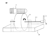
図1は、プラスチックボトル用のプリフォーム1を示す。プリフォーム1はインジェクション(射出)成形法又はPCM(プリフォームコンプレッションモールディング)成形法によって樹脂から成形される。プリフォーム1は、プラスチックボトルのキャップと嵌合する口部1aと、口部1aと隣接する円筒状胴部1bと、円筒状胴部1bの一方の端部を閉塞する底部1cとから成り、試験管のような形状を有する。口部1aの外周面には、キャップの雌ネジと螺合する雄ネジが形成される。プリフォーム1の口部1a側の端部は開いている。
FIG. 1 shows a
プリフォーム1の成形後、プリフォーム1の外周面にはバリアコーティングが形成される。バリアコーティングの形成は、コーティング液をプリフォーム1の外周面に塗布し、プリフォーム1の外周面を乾燥させることによって行われる。このことによって、酸素及び二酸化炭素のようなガスが、プリフォーム1から成形されたプラスチックボトルの内外に透過することを低減し、収容された飲料等の保存寿命を延ばすことができる。また、プラスチックボトルの引掻耐性、防湿性等も向上させることができる。
After the
プラスチックボトルは延伸ブロー成形によってプリフォーム1から成形される。図2(a)〜(d)は、プリフォーム1からプラスチックボトル3を成形するための延伸ブロー成形法を示す。
The plastic bottle is formed from the
最初に、図2(a)に示されるように、プリフォーム1がヒータ40で加熱される。次いで、図2(b)に示されるように、プリフォーム1が金型2に挿入され、金型2が閉じられる。次いで、図2(c)に示されるように、プリフォーム1が延伸ロッド(図示せず)で縦方向に延伸され且つ加圧空気で横方向に延伸される。次いで、図2(d)に示されるように、プリフォーム1が所望の形状まで膨らむと、冷却空気でプラスチックボトル3の内面が冷却され、最終的に、プラスチックボトル3が金型2から取り出される。図3は、プリフォーム1から成形されたプラスチックボトル3を示す。
First, as shown in FIG. 2A, the
以下、図4及び図5を参照して、本発明の実施形態に係るプリフォームコーティング装置について説明する。 Hereinafter, with reference to FIG.4 and FIG.5, the preform coating apparatus which concerns on embodiment of this invention is demonstrated.
図4は、本発明の実施形態に係るプリフォームコーティング装置10の概略図である。プリフォームコーティング装置10はプリフォーム1の外周面にコーティング液を塗布する。プリフォームコーティング装置10は、転写ローラ11と、転写ローラ11の外周面上にプリフォーム1を搬送する搬送装置12と、転写ローラ11の外周面にコーティング液を吐出するダイコータ13と、ダイコータ13に供給するコーティング液を収容する液収容タンク14と、液収容タンク14からダイコータ13にコーティング液を供給するポンプ15とを備える。
FIG. 4 is a schematic view of the
転写ローラ11は、円柱形状を有し、その中心軸111回りに回転する。転写ローラ11の回転は、中心軸111に連結されたハンドルを手で回すことによって、又はモータ等で転写ローラ11を中心軸111回りに回転させることによって行われる。
The
プリフォーム1の搬送経路が図4において矢印で示される。搬送装置12によるプリフォーム1の搬送経路は、転写ローラ11の外周面に沿った略円弧状の経路を含む。プリフォーム1が搬送装置12によって転写ローラ11の外周面上に搬送されると、プリフォーム1の外周面は、転写ローラ11の外周面に沿った略円弧状の経路に沿って、コーティング液が塗布された転写ローラ11の外周面に連続的に回転接触する。このことによって、プリフォーム1を移動させながらコーティング液を転写ローラ11の外周面からプリフォーム1の外周面に転写することができる。コーティング液がプリフォーム1の全周に亘って転写されるように、プリフォーム1に接触する部分の転写ローラ11の周方向長さはプリフォーム1の周方向長さ以上である。この例では、プリフォーム1の外周面は転写ローラ11の略半周に亘って転写ローラ11の外周面に回転接触する。なお、転写ローラ11上のプリフォーム1の搬送経路は、プリフォーム1が転写ローラ11に連続的に回転接触することができれば、転写ローラ11の外周面に沿った略円弧状以外の経路であってもよい。
The conveyance path of the
搬送装置12はプリフォーム1を回転自在に固定することができる。図4の矢印で示されるように、プリフォーム1は搬送装置12によって一つずつ転写ローラ11の外周面上に搬送される。また、複数のプリフォーム1が、一定の間隔で搬送装置12に回転自在に固定され、搬送装置12によって転写ローラ11の外周面上に連続的に搬送されてもよい。さらに、プリフォーム1を一つずつ手作業で転写ローラ11の外周面に沿って回転移動させてもよい。
The conveying
ダイコータ13は、その先端が転写ローラ11の外周面に隣接し又は近接するように配設される。図5は、ダイコータ13の概略斜視図である。図5に示されるように、ダイコータ13には細長のスロット131が形成され、細長のスロット131から転写ローラ11の外周面にコーティング液が面状に吐出される。なお、プリフォームコーティング装置10は、ダイコータ13の代わりに、転写ローラ11の外周面にコーディング液を所定の厚みで塗布するように構成された他の塗布装置を備えてもよい。
The
転写ローラ11の外周面にコーティング液を供給する方法として、別の方法も考えられる。例えば、図7に示されるように、コーティング液が注入された液浸漬タンク31を転写ローラ11の下に配設して、転写ローラ11をコーティング液に直接浸漬させてもよい。この場合、ハンドル32等によって転写ローラ11を回転させると、転写ローラ11の外周面にコーティング液が付着し、その後、転写ローラ11の外周面がプリフォーム1の外周面に回転接触すると、コーティング液が転写ローラ11の外周面からプリフォーム1の外周面に転写される。
Another method is also conceivable as a method for supplying the coating liquid to the outer peripheral surface of the
しかしながら、この方法では、図8に示されるように、転写ローラ11の外周面に供給されたコーティング液の膜厚を一定にするために余分なコーティング液をブレード33で液浸漬タンク31に落とすとき、コーティング液が、空気を巻き込み、液浸漬タンク31内で泡立つことがある。この場合、泡50が混入したコーティング液が液浸漬タンク31から転写ローラ11の外周面に供給されてプリフォーム1の外周面に転写されるので、プリフォーム1の外周面においてコーティング液の膜厚が不均一になる。この問題は、特に高粘度のコーティング液を使用するとき、泡がコーティング液から除去されにくいので、発生しやすい。
However, in this method, as shown in FIG. 8, when the coating liquid supplied to the outer peripheral surface of the
一方、本実施形態では、常にダイコータ13の細長のスロット131から最小限のコーティング液が所定の膜厚になるように直接転写ローラ11の外周面に吐出されるので、コーティング液の泡立ちが生じにくい。したがって、プリフォーム1の外周面に塗布されるコーティング液の膜厚を薄く均一にすることができ、ひいてはプリフォーム1又はプラスチックボトルの不良品の発生を低減することができる。
On the other hand, in this embodiment, since the minimum coating liquid is always discharged directly from the
図4に示されるように、ダイコータ13は第1ホース16を介してポンプ15に連結され、ポンプ15は第2ホース17を介して液収容タンク14に連結される。コーティング液の泡立ちをより一層低減するために、ポンプ15は無脈動ポンプであることが好ましい。液収容タンク14には、コーティング処理の開始前に所望のコーティング液が注入される。また、後述するように、プリフォーム1の外周面に転写されなかったコーティング液が液収容タンク14に戻されて再利用される。液収容タンク14内のコーティング液の量が所定の量よりも少なくなると、コーティング液が液収容タンク14に補充される。
As shown in FIG. 4, the
一般的に、プリフォーム1の口部1a及び底部1cはコーティング無しでもガスの透過性が十分に低い。また、底部1cは他の部分に比べて擦れやすいので、底部1cにコーティングが形成されると、底部1cのコーティングにクラックが生じるおそれがある。
In general, the
コーティング液として、例えば、ガスバリア性を有するポリビニルアルコール(PVA)溶液と、それを保護する非水溶性のコーティング剤とを使用し、プリフォーム1の外周面に最初にPVAコーティングを形成し、その後、保護コーティングでPVAコーティングを覆うことが多い。この場合、PVAが親水性であるため、底部1cの保護コーティングにクラックが生じると、露出したPVAコーティングが水に再溶解してしまうという問題が起こりうる。
As a coating liquid, for example, a polyvinyl alcohol (PVA) solution having gas barrier properties and a water-insoluble coating agent that protects the same are used, and a PVA coating is first formed on the outer peripheral surface of the
したがって、コーティング液は転写ローラ11の外周面からプリフォーム1の円筒状胴部1bのみに転写されることが好ましい。このことによって、プリフォーム1に塗布されたコーティング液の乾燥時間を短くすることもできる。また、円筒状胴部1bは、単純な円筒形状を有するので、転写ローラ11によるコーティング液の塗布が他の部分よりも容易である。
Therefore, the coating liquid is preferably transferred from the outer peripheral surface of the
図4に示されるように、プリフォームコーティング装置10は、さらに、転写ローラ11から落下するコーティング液を受け取る液受けタンク18と、プリフォーム1の外周面に転写されなかったコーティング液を転写ローラ11の外周面から掻き取るスクレーパ19と、スクレーパ19で掻き取られたコーティング液を回収する液回収タンク20とを備える。
As shown in FIG. 4, the
スクレーパ19は転写ローラ11の軸線方向全体に亘って転写ローラ11と接触する。このことによって、プリフォーム1の外周面に転写されなかったコーティング液の大部分を回収することができる。また、スクレーパ19は転写ローラ11の外周面から液回収タンク20に向かって斜め下方に延在する。このことによって、スクレーパ19によって掻き取られたコーティング液は重力によって液回収タンク20に流れ込む。このとき、コーティング液が、空気を巻き込んで、液回収タンク20内で泡立つことがある。
The
図4に示されるように、プリフォームコーティング装置10は、さらに、回収されたコーティング液を脱泡する脱泡装置21を備える。脱泡装置21は第1配管22を介して液回収タンク20に連結され且つ第2配管23を介して液収容タンク14に連結される。脱泡装置21によって、液回収タンク20内で生じた泡50が除去される。脱泡されたコーティング液は、液収容タンク14に戻され、ポンプ15によってダイコータ13に再び供給される。
As shown in FIG. 4, the
以下、プリフォーム1及びプラスチックボトル3の製造方法について説明する。
Hereinafter, the manufacturing method of the
最初に、インジェクション成形法又はPCM成形法によって樹脂からプリフォーム1を成形する。次いで、成形されたプリフォーム1の外周面にコーティング液を塗布する。なお、プリフォーム1へのコーティング液の接着性を高めるために、コーティング液の塗布の前にプリフォーム1の外周面を表面処理してもよい。表面処理は、例えばプラズマ処理、コロナ処理又は電子線処理である。
First, the
コーティング液の塗布は、中心軸111回りに回転する円柱形状の転写ローラ11の外周面にコーティング液をダイコータ13のスロット131から吐出することと、プリフォーム1を転写ローラ11の外周面上に搬送し、転写ローラ11の外周面からプリフォーム1の外周面にコーティング液を転写することと、によって行われる。プリフォーム1の外周面に転写されなかったコーティング液はスクレーパ19で回収される。その後、回収されたコーティング液は、脱泡装置21で脱泡されて、再び転写ローラ11の外周面にダイコータ13のスロット131から吐出される。なお、転写ローラ11の外周面上へのコーティング液の供給は、ダイコータ13の代わりに、転写ローラ11の外周面にコーディング液を所定の厚みで塗布するように構成された他の塗布装置によって行われてもよい。
The coating liquid is applied by discharging the coating liquid from the
前述したように、コーティング液は転写ローラ11の外周面からプリフォーム1の円筒状胴部1bのみに転写されることが好ましい。また、プリフォーム1に接触する部分の転写ローラ11の周方向長さはプリフォーム1の周方向長さ以上であり、プリフォーム1は搬送装置12によって転写ローラ11の外周面上に連続的に搬送されることができる。このことによって、多数のプリフォーム1の外周面の全周にコーティング液を短時間で効率的に塗布することができる。
As described above, the coating liquid is preferably transferred from the outer peripheral surface of the
コーティング液の塗布後、プリフォーム1の外周面を搬送装置12上で乾燥させる。乾燥は二段階で行われる。第1段階では、プリフォーム1はカーボンヒータで急速に加熱される。第2段階では、プリフォーム1は遠赤外線ヒータで熱風乾燥されて温度が保持される。この結果、プリフォーム1の外周面にはコーティングが形成される。
After the coating liquid is applied, the outer peripheral surface of the
コーティング液として、例えば、ガスバリア性を有するPVA溶液と、それを保護する非水溶性のコーティング剤とが使用される。この場合、プリフォーム1の外周面に最初にPVAコーティングを形成し、その後、PVAコーティングが露出しないように、保護コーティングでPVAコーティングを覆う。二層のコーティングの形成は、コーティング液を交換することで一つのプリフォームコーティング装置10を使用し、又は二つのプリフォームコーティング装置10を使用してもよい。なお、PVAを保護する非水溶性のコーティング剤は、例えば、ポリオレフィン分散溶液、各種変性ポリオレフィン分散溶液、ポリビニルブチラール(PVB)溶液等である。
As the coating liquid, for example, a PVA solution having gas barrier properties and a water-insoluble coating agent that protects the PVA solution are used. In this case, the PVA coating is first formed on the outer peripheral surface of the
また、PVAを保護する非水溶性のコーティング剤は、典型的には、粘性が低く、PVA溶液よりも薄く塗布されるので、その乾燥時間はPVA溶液よりも短い。このため、過剰な加熱によってプリフォーム1が白化することが少ない。したがって、PVAを保護する非水溶性のコーティング剤の塗布は、従来のようにプリフォーム1を鉛直方向に浸漬すること等によって行われてもよい。この場合、プリフォーム1の底部1cにも保護コーティングが形成されうるが、PVAコーティングが底部1cに形成されていなければ、底部1cの保護コーティングのクラックが生じても、親水性であるPVAが水に再溶解するという問題は発生しない。
In addition, the water-insoluble coating agent that protects PVA typically has a low viscosity and is applied thinner than the PVA solution, so that its drying time is shorter than that of the PVA solution. For this reason, the
コーティング液の他の例は、水溶性ポリアミド、水溶性ポリエステル、ポリ塩化ビニリデン(PVDC)、ポリアクリロニトリル、エチレン・ビニルアルコール共重合樹脂(EVOH)、ポリグリコール酸等のバリア樹脂の溶液、及びこれらに無機物、酸化吸収剤等を混合した溶液と、エポキシ系、ウレタン系又はフェノール系のような熱硬化性接着剤と、ホットメルト樹脂等の熱可塑性接着剤と、水性インキ又は溶剤系インキのような塗料とである。 Other examples of coating solutions include water-soluble polyamides, water-soluble polyesters, polyvinylidene chloride (PVDC), polyacrylonitrile, ethylene / vinyl alcohol copolymer resins (EVOH), solutions of barrier resins such as polyglycolic acid, and the like. Solutions mixed with inorganic substances, oxidative absorbers, thermosetting adhesives such as epoxy, urethane or phenolic, thermoplastic adhesives such as hot melt resins, and water-based or solvent-based inks With paint.
上述したように、プリフォーム1の外周面においてコーティング液の膜厚が不均一になるという問題は、特に高粘度のコーティング液を使用するときに発生しやすい。このため、高粘度のコーティング液を使用するときに本実施形態を適用することで、より顕著な作用効果を奏することができる。例えば、本実施形態に用いられるコーティング液の粘度は、好ましくは1mPa・s以上であり、より好ましくは100mPa・s以上である。
As described above, the problem that the film thickness of the coating liquid is not uniform on the outer peripheral surface of the
プラスチックボトル3は、上記の製造方法によって製造されたプリフォーム1を延伸ブロー成形することによって製造される。
The
1 プリフォーム
1a 口部
1b 円筒状胴部
1c 底部
2 金型
3 プラスチックボトル
10 プリフォームコーティング装置
11 転写ローラ
111 中心軸
12 搬送装置
13 ダイコータ
131 スロット
14 液収容タンク
15 ポンプ
16 第1ホース
17 第2ホース
18 液受けタンク
19 スクレーパ
20 液回収タンク
21 脱泡装置
22 第1配管
23 第2配管
31 液浸漬タンク
32 ハンドル
33 ブレード
40 ヒータ
50 泡
DESCRIPTION OF
Claims (12)
前記転写ローラの外周面にコーティング液を所定の厚みで塗布する塗布装置と、
を備え、
前記転写ローラの外周面がプリフォームの外周面に回転接触することによって、前記コーティング液が該転写ローラの外周面から該プリフォームの外周面に転写される、プリフォームコーティング装置。 A cylindrical transfer roller that rotates about a central axis;
An applicator for applying a coating liquid to the outer peripheral surface of the transfer roller at a predetermined thickness;
With
A preform coating apparatus in which the coating liquid is transferred from the outer peripheral surface of the transfer roller to the outer peripheral surface of the preform when the outer peripheral surface of the transfer roller is in rotational contact with the outer peripheral surface of the preform.
前記プリフォームの搬送経路が、前記転写ローラの外周面に沿った略円弧状の経路を含む、請求項1に記載のプリフォームコーティング装置。 Furthermore, a transport device for transporting the preform is provided,
The preform coating apparatus according to claim 1, wherein the preform conveyance path includes a substantially arc-shaped path along an outer peripheral surface of the transfer roller.
プリフォームを前記転写ローラの外周面上に搬送し、該転写ローラの外周面から該プリフォームの外周面に前記コーティング液を転写するステップと、
前記プリフォームの外周面を乾燥させるステップと
を含む、プリフォームの製造方法。 Applying a coating liquid with a predetermined thickness on the outer peripheral surface of a cylindrical transfer roller rotating around a central axis with a coating device;
Conveying the preform onto the outer peripheral surface of the transfer roller, and transferring the coating liquid from the outer peripheral surface of the transfer roller to the outer peripheral surface of the preform;
Drying the outer peripheral surface of the preform.
Priority Applications (8)
| Application Number | Priority Date | Filing Date | Title |
|---|---|---|---|
| JP2014078114A JP2015199012A (en) | 2014-04-04 | 2014-04-04 | Preform coating device, preform production method, and plastic bottle production method |
| EP15773631.5A EP3127618A4 (en) | 2014-04-04 | 2015-04-03 | Preform coating device, method for manufacturing preform, and method for manufacturing plastic bottle |
| US15/300,027 US20170136677A1 (en) | 2014-04-04 | 2015-04-03 | Preform coating device, method for manufacturing preform, and method for manufacturing plastic bottle |
| SG11201607420PA SG11201607420PA (en) | 2014-04-04 | 2015-04-03 | Preform coating device, method for manufacturing preform, and method for manufacturing plastic bottle |
| CN201580012409.8A CN106061626A (en) | 2014-04-04 | 2015-04-03 | Preform coating device, method for manufacturing preform, and method for manufacturing plastic bottle |
| CA2942286A CA2942286A1 (en) | 2014-04-04 | 2015-04-03 | Preform coating device, method for manufacturing preform, and method for manufacturing plastic bottle |
| AU2015242787A AU2015242787A1 (en) | 2014-04-04 | 2015-04-03 | Preform coating device, method for manufacturing preform, and method for manufacturing plastic bottle |
| PCT/JP2015/060638 WO2015152408A1 (en) | 2014-04-04 | 2015-04-03 | Preform coating device, method for manufacturing preform, and method for manufacturing plastic bottle |
Applications Claiming Priority (1)
| Application Number | Priority Date | Filing Date | Title |
|---|---|---|---|
| JP2014078114A JP2015199012A (en) | 2014-04-04 | 2014-04-04 | Preform coating device, preform production method, and plastic bottle production method |
Publications (1)
| Publication Number | Publication Date |
|---|---|
| JP2015199012A true JP2015199012A (en) | 2015-11-12 |
Family
ID=54240715
Family Applications (1)
| Application Number | Title | Priority Date | Filing Date |
|---|---|---|---|
| JP2014078114A Pending JP2015199012A (en) | 2014-04-04 | 2014-04-04 | Preform coating device, preform production method, and plastic bottle production method |
Country Status (8)
| Country | Link |
|---|---|
| US (1) | US20170136677A1 (en) |
| EP (1) | EP3127618A4 (en) |
| JP (1) | JP2015199012A (en) |
| CN (1) | CN106061626A (en) |
| AU (1) | AU2015242787A1 (en) |
| CA (1) | CA2942286A1 (en) |
| SG (1) | SG11201607420PA (en) |
| WO (1) | WO2015152408A1 (en) |
Cited By (4)
| Publication number | Priority date | Publication date | Assignee | Title |
|---|---|---|---|---|
| WO2019131686A1 (en) * | 2017-12-25 | 2019-07-04 | サントリーホールディングス株式会社 | Preform coating device |
| WO2019131687A1 (en) * | 2017-12-25 | 2019-07-04 | サントリーホールディングス株式会社 | Preform coating device |
| WO2019131678A1 (en) * | 2017-12-25 | 2019-07-04 | サントリーホールディングス株式会社 | Preform coating device |
| WO2019131681A1 (en) * | 2017-12-25 | 2019-07-04 | サントリーホールディングス株式会社 | Preform coating device |
Families Citing this family (4)
| Publication number | Priority date | Publication date | Assignee | Title |
|---|---|---|---|---|
| EP3357588B1 (en) | 2015-09-30 | 2021-07-21 | Suntory Holdings Limited | Preform coating device and preform coating method |
| RU2709861C1 (en) * | 2016-01-08 | 2019-12-23 | Джонсон Мэтти Паблик Лимитед Компани | Method and device for coating application on end surface of monolithic substrate of neutralizer |
| WO2019216428A1 (en) * | 2018-05-10 | 2019-11-14 | サントリーホールディングス株式会社 | Method for coating preform for plastic bottle |
| US20230129901A1 (en) * | 2021-10-21 | 2023-04-27 | Gerhard Designing & Manufacturing Inc. | Excess coating removal device for can coating machines |
Citations (6)
| Publication number | Priority date | Publication date | Assignee | Title |
|---|---|---|---|---|
| JPH0611863U (en) * | 1992-07-08 | 1994-02-15 | 大日本スクリーン製造株式会社 | Roll coater |
| JPH09192568A (en) * | 1996-01-22 | 1997-07-29 | Chugai Ro Co Ltd | Apparatus for supplying coating material to die coater |
| DE102004036275A1 (en) * | 2004-07-27 | 2006-02-16 | Krones Ag | Coating device for e.g. preforms, bottles, includes outlined applicator roller for applying coating material on coating rollers |
| JP2012250190A (en) * | 2011-06-03 | 2012-12-20 | Hirano Tecseed Co Ltd | Coating apparatus |
| JP2012250771A (en) * | 2011-06-06 | 2012-12-20 | Kuraray Europe Gmbh | Plastic containers with gas barrier coating and optionally hydrophilic inside coating |
| JP2014151632A (en) * | 2013-02-13 | 2014-08-25 | Suntory Holdings Ltd | Preform for a plastic bottle possessing gas barrier coating |
Family Cites Families (6)
| Publication number | Priority date | Publication date | Assignee | Title |
|---|---|---|---|---|
| US3677801A (en) * | 1970-07-28 | 1972-07-18 | Dart Ind Inc | Method of coating irregular objects |
| JPS58906B2 (en) * | 1979-04-09 | 1983-01-08 | 麒麟麦酒株式会社 | Coating equipment for bottles, etc. |
| IE72977B1 (en) * | 1990-07-04 | 1997-05-07 | John W Cahill | A process for molding a multiple layer structure and a container made therefrom |
| CA2243388A1 (en) * | 1996-01-22 | 1997-07-31 | Chugai Ro Co., Ltd. | Method of and apparatus for applying coating liquid to base plate by die coater and apparatus for supplying coating liquid to die coater |
| MX2009008201A (en) * | 2007-01-31 | 2009-08-12 | Alpla Werke | Method for coating some areas of hollow elements. |
| CN103660103B (en) * | 2013-12-12 | 2016-08-24 | 上海交通大学 | Film double-sided micro structure volume to volume UV solidifying and molding device based on belt mould |
-
2014
- 2014-04-04 JP JP2014078114A patent/JP2015199012A/en active Pending
-
2015
- 2015-04-03 AU AU2015242787A patent/AU2015242787A1/en not_active Abandoned
- 2015-04-03 EP EP15773631.5A patent/EP3127618A4/en not_active Withdrawn
- 2015-04-03 CN CN201580012409.8A patent/CN106061626A/en active Pending
- 2015-04-03 CA CA2942286A patent/CA2942286A1/en not_active Abandoned
- 2015-04-03 SG SG11201607420PA patent/SG11201607420PA/en unknown
- 2015-04-03 US US15/300,027 patent/US20170136677A1/en not_active Abandoned
- 2015-04-03 WO PCT/JP2015/060638 patent/WO2015152408A1/en active Application Filing
Patent Citations (6)
| Publication number | Priority date | Publication date | Assignee | Title |
|---|---|---|---|---|
| JPH0611863U (en) * | 1992-07-08 | 1994-02-15 | 大日本スクリーン製造株式会社 | Roll coater |
| JPH09192568A (en) * | 1996-01-22 | 1997-07-29 | Chugai Ro Co Ltd | Apparatus for supplying coating material to die coater |
| DE102004036275A1 (en) * | 2004-07-27 | 2006-02-16 | Krones Ag | Coating device for e.g. preforms, bottles, includes outlined applicator roller for applying coating material on coating rollers |
| JP2012250190A (en) * | 2011-06-03 | 2012-12-20 | Hirano Tecseed Co Ltd | Coating apparatus |
| JP2012250771A (en) * | 2011-06-06 | 2012-12-20 | Kuraray Europe Gmbh | Plastic containers with gas barrier coating and optionally hydrophilic inside coating |
| JP2014151632A (en) * | 2013-02-13 | 2014-08-25 | Suntory Holdings Ltd | Preform for a plastic bottle possessing gas barrier coating |
Cited By (16)
| Publication number | Priority date | Publication date | Assignee | Title |
|---|---|---|---|---|
| WO2019131686A1 (en) * | 2017-12-25 | 2019-07-04 | サントリーホールディングス株式会社 | Preform coating device |
| WO2019131687A1 (en) * | 2017-12-25 | 2019-07-04 | サントリーホールディングス株式会社 | Preform coating device |
| WO2019131678A1 (en) * | 2017-12-25 | 2019-07-04 | サントリーホールディングス株式会社 | Preform coating device |
| WO2019131681A1 (en) * | 2017-12-25 | 2019-07-04 | サントリーホールディングス株式会社 | Preform coating device |
| CN111491743A (en) * | 2017-12-25 | 2020-08-04 | 三得利控股株式会社 | Preform coating apparatus |
| CN111491744A (en) * | 2017-12-25 | 2020-08-04 | 三得利控股株式会社 | Preform coating apparatus |
| JPWO2019131681A1 (en) * | 2017-12-25 | 2020-12-24 | サントリーホールディングス株式会社 | Preform coating equipment |
| JPWO2019131687A1 (en) * | 2017-12-25 | 2020-12-24 | サントリーホールディングス株式会社 | Preform coating equipment |
| JPWO2019131686A1 (en) * | 2017-12-25 | 2020-12-24 | サントリーホールディングス株式会社 | Preform coating equipment |
| JPWO2019131678A1 (en) * | 2017-12-25 | 2020-12-24 | サントリーホールディングス株式会社 | Preform coating equipment |
| JP7016889B2 (en) | 2017-12-25 | 2022-02-07 | サントリーホールディングス株式会社 | Preform coating equipment |
| JP7016887B2 (en) | 2017-12-25 | 2022-02-07 | サントリーホールディングス株式会社 | Preform coating equipment |
| JP7016890B2 (en) | 2017-12-25 | 2022-02-07 | サントリーホールディングス株式会社 | Preform coating equipment |
| JP7016888B2 (en) | 2017-12-25 | 2022-02-07 | サントリーホールディングス株式会社 | Preform coating equipment |
| US11453027B2 (en) | 2017-12-25 | 2022-09-27 | Suntory Holdings Limited | Preform coating device |
| US11511310B2 (en) | 2017-12-25 | 2022-11-29 | Suntory Holdings Limited | Preform coating device |
Also Published As
| Publication number | Publication date |
|---|---|
| EP3127618A1 (en) | 2017-02-08 |
| EP3127618A4 (en) | 2017-12-20 |
| CA2942286A1 (en) | 2015-10-08 |
| WO2015152408A1 (en) | 2015-10-08 |
| US20170136677A1 (en) | 2017-05-18 |
| CN106061626A (en) | 2016-10-26 |
| AU2015242787A1 (en) | 2016-10-06 |
| SG11201607420PA (en) | 2016-10-28 |
Similar Documents
| Publication | Publication Date | Title |
|---|---|---|
| WO2015152408A1 (en) | Preform coating device, method for manufacturing preform, and method for manufacturing plastic bottle | |
| WO2017057198A1 (en) | Preform coating device and preform coating method | |
| JP6537429B2 (en) | Preform coating equipment | |
| JP6537426B2 (en) | Preform coating apparatus and preform coating method | |
| JP7016888B2 (en) | Preform coating equipment | |
| JP7016890B2 (en) | Preform coating equipment | |
| JP6628535B2 (en) | Preform coating method | |
| JP7016887B2 (en) | Preform coating equipment | |
| JP7016889B2 (en) | Preform coating equipment | |
| JP4335041B2 (en) | Preform heating method | |
| NZ741019B2 (en) | Preform coating device and preform coating method |
Legal Events
| Date | Code | Title | Description |
|---|---|---|---|
| A621 | Written request for application examination |
Free format text: JAPANESE INTERMEDIATE CODE: A621 Effective date: 20160824 |
|
| A131 | Notification of reasons for refusal |
Free format text: JAPANESE INTERMEDIATE CODE: A131 Effective date: 20170606 |
|
| A521 | Request for written amendment filed |
Free format text: JAPANESE INTERMEDIATE CODE: A523 Effective date: 20170724 |
|
| A02 | Decision of refusal |
Free format text: JAPANESE INTERMEDIATE CODE: A02 Effective date: 20180109 |