JP2015196330A - Image formation device - Google Patents
Image formation device Download PDFInfo
- Publication number
- JP2015196330A JP2015196330A JP2014075829A JP2014075829A JP2015196330A JP 2015196330 A JP2015196330 A JP 2015196330A JP 2014075829 A JP2014075829 A JP 2014075829A JP 2014075829 A JP2014075829 A JP 2014075829A JP 2015196330 A JP2015196330 A JP 2015196330A
- Authority
- JP
- Japan
- Prior art keywords
- sheet
- image forming
- roller
- image
- shaft
- Prior art date
- Legal status (The legal status is an assumption and is not a legal conclusion. Google has not performed a legal analysis and makes no representation as to the accuracy of the status listed.)
- Pending
Links
Images
Landscapes
- Handling Of Cut Paper (AREA)
- Paper Feeding For Electrophotography (AREA)
- Delivering By Means Of Belts And Rollers (AREA)
- Registering Or Overturning Sheets (AREA)
Abstract
【課題】 画像が形成されるシートを搬送するシート搬送手段において高コスト化や形状の不安定さを招くことなく画像汚れを防止することが困難だった。【解決手段】 画像形成装置のシート搬送手段は、駆動が伝達されて回転する軸54と、軸54に取り付けられ、搬送されるシートと外周が接するローラ部55と、を備えた搬送ローラ53と、搬送ローラ53のローラ部55に圧接するピンチローラ51と、を有し、ピンチローラ51は成型によって外表面に形成された段差52を有し、軸54またはローラ部55の一方の、段差に対応した位置に、凹形状56が形成されている。【選択図】 図1PROBLEM TO BE SOLVED: To prevent image smearing without incurring high cost and unstable shape in a sheet conveying means for conveying a sheet on which an image is formed. A sheet conveyance unit of an image forming apparatus includes a conveyance roller 53 including a shaft 54 that is rotated by transmission of a drive, and a roller portion 55 that is attached to the shaft 54 and is in contact with a sheet to be conveyed and an outer periphery thereof. A pinch roller 51 pressed against the roller portion 55 of the conveying roller 53. The pinch roller 51 has a step 52 formed on the outer surface by molding. A concave shape 56 is formed at a corresponding position. [Selection] Figure 1
Description
本発明は、シートに画像を形成する画像形成装置に関するものである。 The present invention relates to an image forming apparatus that forms an image on a sheet.
複写機、プリンタ、ファクシミリ等の画像形成装置においては、シートを搬送しながらシートに画像を形成する。シートを搬送するために、駆動力を伝達して回転する搬送ローラと、シートを搬送ローラに押圧する樹脂製のピンチローラとを有する構成が一般的である。 In an image forming apparatus such as a copying machine, a printer, or a facsimile, an image is formed on a sheet while the sheet is conveyed. In order to convey the sheet, a configuration having a conveyance roller that rotates by transmitting a driving force and a resin pinch roller that presses the sheet against the conveyance roller is generally used.
画像が形成されたシートが搬送ローラとピンチローラとによって搬送される時、ピンチローラはシートの画像が形成された面(画像形成面)に接する。この時、成型時に発生したピンチローラのパーティングラインの段差やバリが画像形成面と当接し、画像にダメージを与え、段差やバリでピンチローラにトナーが付着堆積する。 When a sheet on which an image is formed is conveyed by a conveying roller and a pinch roller, the pinch roller contacts a surface (image forming surface) on which the image of the sheet is formed. At this time, a step or burr in the parting line of the pinch roller generated during molding contacts the image forming surface, damages the image, and toner adheres to and accumulates on the pinch roller due to the step or burr.
この画像ダメージおよび汚れを防止するため、特許文献1に構成が開示されている。特許文献1では、成型時に発生したパーティングラインの段差やバリを後加工により除去することにより、非搬送物へのダメージを防止している。 In order to prevent this image damage and dirt, a configuration is disclosed in Patent Document 1. In Patent Document 1, damage to a non-conveyed object is prevented by removing a step or a burr of a parting line generated during molding by post-processing.
しかしながら、上述した特許文献1の技術においては、パーティングラインに突出する段差やバリを後加工するため、コストが高い。 However, in the technique of Patent Document 1 described above, the steps and burrs protruding on the parting line are post-processed, and thus the cost is high.
本発明の目的は、高コスト化を招くことなく、画像汚れを防止することである。 An object of the present invention is to prevent image smearing without increasing the cost.
上記目的を達成するための本発明の画像形成装置は、シートに画像を形成する画像形成手段と、前記画像形成手段によって画像が形成されたシートを搬送するシート搬送手段と、を有する画像形成装置であって、前記シート搬送手段は、駆動が伝達されて回転する軸と、前記軸に取り付けられ、搬送されるシートと外周が接するローラ部と、を備えた駆動回転体と、前記駆動回転体のローラ部に圧接する従動回転体と、を有し、前記従動回転体は成型によって外表面に形成された段差を有し、前記軸または前記ローラ部の一方の、前記段差に対応した位置に、凹形状が形成されていることを特徴とする。 In order to achieve the above object, an image forming apparatus of the present invention includes an image forming unit that forms an image on a sheet, and a sheet conveying unit that conveys a sheet on which an image is formed by the image forming unit. The sheet conveying means includes a drive rotating body that includes a shaft that rotates when driving is transmitted thereto, and a roller unit that is attached to the shaft and that contacts the outer periphery of the sheet to be conveyed, and the drive rotating body. A driven rotor that is in pressure contact with the roller portion, and the driven rotor has a step formed on the outer surface by molding, at one of the shaft or the roller portion at a position corresponding to the step. A concave shape is formed.
以上説明したように、本発明によれば、高コスト化を招くことなく、画像汚れを防止することが出来る。 As described above, according to the present invention, it is possible to prevent image smearing without increasing the cost.
(第1実施形態)
本発明の第1実施形態について図1および図2に基づいて説明する。なお、本実施形態では画像形成装置としてレーザプリンタを例示している。
(First embodiment)
A first embodiment of the present invention will be described with reference to FIGS. 1 and 2. In this embodiment, a laser printer is exemplified as the image forming apparatus.
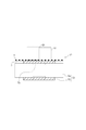
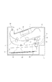
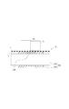
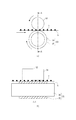
図1は、画像形成装置に配置されたシート搬送手段の構成を示す概略断面図である。図2は画像形成装置の断面図である。 FIG. 1 is a schematic cross-sectional view illustrating a configuration of a sheet conveying unit disposed in the image forming apparatus. FIG. 2 is a cross-sectional view of the image forming apparatus.
まず、シートSの流れに沿って概略的な構成を説明する。図2に示すように、画像形成装置Eは電子写真方式によって画像を形成する。画像形成装置Eでは、シートSを画像形成手段2へ搬送してトナー像を転写する。そして、そのシートSを定着手段3へ搬送してトナーをシートに定着したあと、排出部15へと排出する。
First, a schematic configuration will be described along the flow of the sheet S. As shown in FIG. 2, the image forming apparatus E forms an image by an electrophotographic method. In the image forming apparatus E, the sheet S is conveyed to the
具体的には、装置下部に、シートSを積載収納するカセット11が装填されている。カセット11内に積載収納されているシートSが、反時計回り方向に回転する給送ローラ12によって最上位のシートSから順に繰り出され、搬送ローラ対13、14により画像形成手段2に送られる。また、搬送ローラ対14はシート先端のレジストレーションをとる機能を有する。
Specifically, a cassette 11 for loading and storing sheets S is loaded at the lower part of the apparatus. The sheets S stacked and stored in the cassette 11 are sequentially fed out from the uppermost sheet S by the
画像形成手段2では、シートSの通過を検知した後、所定時間経過後にレーザースキャナー21によって、画像情報に応じたレーザー光が時計回り方向に回転している感光体22上に照射され、感光体22上には静電潜像が形成される。この静電潜像はプロセスカートリッジP内の現像部にてトナー現像される。感光体22上に形成されたトナー画像は、転写ローラ24により未定着画像としてシートSに転写される。
In the
未定着画像を担持したシートSは、定着手段3に送られ、定着手段3における定着ユニットにて定着処理がなされる。定着手段3を通過して定着処理を終えたシートSは排出搬送ローラ対33により搬送され、装置上部の排出部15に排出される。
The sheet S carrying the unfixed image is sent to the
シートSの両面に記録を行う場合には、定着手段3を通過して一方の面に画像が形成されたシートSを排出搬送ローラ対33の逆転駆動によりスイッチバック搬送する。排出搬送ローラ対33が逆転駆動されるとシートは、再搬送路16に搬送される。そして、シートSは、再搬送路16に配置された搬送ローラ対41、42により、再度、画像形成手段2へ向けて搬送される。搬送ローラ対41はシートSの搬送方向と直角方向の位置合わせ(横レジストレーション)を行う。つまり、搬送ローラ対41の駆動ローラに圧接するピンチローラの軸線が駆動ローラの軸線に対して所定角度傾くようにピンチローラが配置されていて、シートを斜送する。そして、搬送ローラ対41に斜送されるシートの側端が不図示の基準ガイドに当接する。基準ガイドがシートの幅方向での位置を規制することで、シートSの搬送方向と直角方向の位置合わせ(横レジストレーション)が行われる。そして、画像形成手段2に搬送されたシートは、他方の面に画像が形成された後に排出搬送ローラ対33によって機外へ排出される。
When recording is performed on both sides of the sheet S, the sheet S having the image formed on one side after passing through the
シートを搬送するシート搬送手段として、搬送ローラ対42を例にあげて詳しく説明する。なお、排出搬送ローラ対33、搬送ローラ対41も、搬送ローラ対42と同様の構成である。
The sheet conveying means for conveying the sheet will be described in detail by taking the conveying
図1に示したように、搬送ローラ対42は、ピンチローラ51とピンチローラ51が圧接される搬送ローラ53とによって構成される。シートを搬送するためピンチローラ51は弾性部材(不図示)によって、搬送ローラ53に付勢されている。
As shown in FIG. 1, the
ピンチローラ51は樹脂製であり、金型によって成型されるため略中央部にパーティングラインによる段差52がある。つまり、段差52は、ピンチローラ51の成型時に外表面に形成された段差である。この段差52は金型合わせ面であるためエッジ形状でありバリが発生しやすい。なお、図中の段差52は理解しやすくするために書かれているが、実際の段差は0.2mm程度以下の微小な段差である。
Since the
駆動回転体としての搬送ローラ53は、54とローラ部55で構成されている。軸54は不図示のモータからの駆動を受けて回転する。外周がシートと接するローラ部55はゴム製であり、円筒形状の軸54とともに回転するように軸54に取り付けられている。また、軸54の、従動回転体としてのピンチローラ51のパーティングによる段差52と対向(対応)する位置(軸方向での位置)には、凹形状56が形成されている。凹形状56は、軸54の外周において周方向に沿って連続的に形成された溝である。ここで、凹形状56が段差52に対応した位置に配置されているとは、軸方向において凹形状56の幅内に段差52が位置するように、凹形状56が配置されることである。
The conveyance roller 53 as a drive rotator is composed of a
軸方向において凹形状56が段差52を含むように配置されることである。
The concave shape 56 is arranged so as to include the
軸54には凹形状56が設けられているため、凹形状56に対応した位置でのニップ圧はその他の領域に比べ低くなっている。
Since the
次に機能について、シートの搬送に合わせて説明する。 Next, functions will be described in accordance with sheet conveyance.
画像が形成されたシートSが搬送ローラ対42によって搬送される時、ピンチローラ51は、シートのうちの画像が形成された面(画像形成面)に圧接しシートSを搬送する。
When the sheet S on which an image is formed is conveyed by the
この時、パーティングラインの段差52が画像形成面と当接するが、軸54が凹形状56となっているため、段差52に対応した位置でのピンチローラ圧は比較的低く、トナーTが段差52に付着しにくい。また、段差52によって画像へダメージを与えにくい。シートSの搬送を終了した後、ピンチローラ51は搬送ローラ53と当接し従動回転する。この時、ピンチローラ51に付着したトナーTは、ピンチローラ51より比較的離形性の悪いローラ部55に転写される虞がある。しかし、この時においても、本実施形態では、軸54が凹形状56となっているため比較的接触圧が低く、トナーTは転写されにくい。
At this time, the
次に、搬送ローラ対42によって後続紙を搬送すると、先行紙からローラ部55に転写したトナーTがシートSの非画像形成面(シートの画像形成面とは反対側の面)に付着する虞がある。しかし、この時においても、軸54が凹形状56となっているため比較的ピンチローラ圧が低くトナーTが後続紙に付着しにくい。
Next, when the succeeding sheet is conveyed by the conveying
この様に、凹形状56に対応した箇所で当接圧が低いため、シートSの表面からピンチローラ51、ピンチローラ51からローラ部55、ローラ部55からシートS裏面へとトナーTが転写される量が少ない。よって、最終的にシートの裏面へのトナーの転写はほとんどなくなる。
As described above, since the contact pressure is low at the portion corresponding to the concave shape 56, the toner T is transferred from the front surface of the sheet S to the
(比較例)
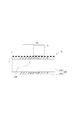
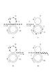
図6および図7に比較例を示した。図6は、比較例の構成を表す模式図であり、図7は画像形成されたシートが連続搬送される時の模式図である。図中の矢印はシートSの搬送方向およびローラの回転方向を示す。
(Comparative example)
6 and 7 show comparative examples. FIG. 6 is a schematic diagram illustrating a configuration of a comparative example, and FIG. 7 is a schematic diagram when a sheet on which an image is formed is continuously conveyed. The arrows in the figure indicate the conveyance direction of the sheet S and the rotation direction of the rollers.
搬送ローラ93は駆動力が伝達される軸94とシートと当接するローラ部95で構成されている。ピンチローラ91には、外周面に金型合わせ面であるパーティングラインが形成される。パーティングラインは通常、ピンチローラ91の中央部または端部に設定する。このパーティングラインは段差やバリ(エッジ形状)92となる。
The conveying
画像が形成されたシートSが搬送ローラ93およびピンチローラ91によって搬送される時、ピンチローラ91は画像形成面に圧接しシートSを搬送する。この時、パーティングラインの段差やバリ92が画像形成面と当接し、画像にダメージを与え、ピンチローラ91にトナーTが付着堆積する(図7(a)参照)。
When the sheet S on which the image is formed is conveyed by the conveying
シートSの搬送が終了した後、ピンチローラ91は搬送ローラ93と当接し従動回転する(図7(b)参照)。この時、ピンチローラ91に付着したトナーTは、ピンチローラ91より比較的離形性の悪い搬送ローラ93に転写される(図7(c))。次に、搬送ローラ93およびピンチローラ91が後続紙を搬送すると、搬送ローラ93に転写したトナーTがシートSの非画像形成面に付着する(図7d)。シートSの表面への画像形成のみの場合は、裏面への汚れの付着となる。また、シートSの表裏両面への画像形成する場合は、裏面の画像形成面が汚れることとなる。
After the conveyance of the sheet S is completed, the
このような比較例と比較して本実施形態では、段差52と対向する位置に凹形状56が設けられている。したがって、既述したように、凹形状56におけるピンチローラ圧はその他の領域に比べ低くなっている。この結果、段差52が画像へのダメージを与えにくい。また、トナーが転写される際の当接圧が低いので、トナーの転写(シートからピンチローラへのトナーの転写等)が生じづらい。よって、最終的にシート裏面へのトナー転写はほとんどなくなる。
In the present embodiment, a concave shape 56 is provided at a position facing the
(第2実施形態)
本発明の第2実施形態について図3に基づいて説明する。なお、本実施形態において、前述した第1実施形態で説明したものと同じ構成には同一の符号を示す。また、第1実施形態と同様の構成および機能についての説明は省略し、本実施形態の特徴部分についてのみ説明する。
(Second Embodiment)
A second embodiment of the present invention will be described with reference to FIG. In the present embodiment, the same components as those described in the first embodiment are denoted by the same reference numerals. Further, the description of the same configuration and function as in the first embodiment is omitted, and only the characteristic part of the present embodiment will be described.
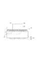
図3は、シート搬送手段を示す概略断面図(パーティングラインを端部に設定した場合)である。 FIG. 3 is a schematic sectional view showing the sheet conveying means (when the parting line is set at the end).
第2実施形態を、搬送ローラ対42を例にあげて詳しく説明する。なお、排出搬送ローラ対33、搬送ローラ対41も、搬送ローラ対42と同様の構成である。
The second embodiment will be described in detail by taking the
ピンチローラ251は樹脂製であり、金型によって成型されるため端部のどちらか一方にパーティングラインによるバリ(段差やエッジ)252が発生する(図中は便宜上両端部を図示する)。このバリ252は金型合わせ面であるため段差やバリが発生しやすい。
Since the
搬送ローラ253は、軸254と、軸254に取り付けられるゴム製のローラ部255で構成されている。軸254は不図示のモータからの駆動を受けて回転する。ローラ部255はシート搬送のためゴム製であり、軸254とともに回転するように取り付けられている。また、ローラ部255の内周面側(内周部)の、ピンチローラ251のバリ252と対向する位置に、凹形状256が形成されている。
The
バリ252はどちらか一方の端部に設定されるが、どちらに設定されても対応可能な様に、本実施形態では両側端部に対応する位置に、凹形状256を設けている。凹形状256を一つだけ設け、組み付け時に凹形状256がバリ252に対応するようにしてもよい。
The
シートを搬送するためピンチローラ251は弾性部材(不図示)によって、搬送ローラ253に付勢されている。
In order to convey the sheet, the
ローラ部255には凹形状256が設けられているため、凹形状部のニップ圧はその他の領域に比べ低くなっている。
Since the
次に機能について、シートの搬送に合わせて説明する。 Next, functions will be described in accordance with sheet conveyance.
画像が形成されたシートSが搬送ローラ対42によって搬送される時、ピンチローラ251は画像形成面に圧接しシートSを搬送する。
When the sheet S on which the image is formed is conveyed by the conveying
この時、バリ252が画像形成面と当接するが、ローラ部255が凹形状256となっているため、バリ252のピンチローラ圧は比較的低く、トナーTがバリ252に付着しにくい。また、バリ252によって画像へダメージを与えにくい。シートSの搬送を終了した後、ピンチローラ251は搬送ローラ253と当接し従動回転する。この時、ピンチローラ251に付着したトナーTは、ピンチローラ251より比較的離形性の悪いローラ部255に転写される虞がある。しかし、この時においても、ローラ部255が凹形状256となっているため比較的接触圧が低く、トナーTは転写されにくい。
At this time, the
次に、搬送ローラ対42によって後続紙を搬送すると、先行紙からローラ部255に転写したトナーTがシートSの非画像形成面に付着する虞がある。しかし、この時においても、ローラ部255が凹形状256となっているため比較的ピンチローラ圧が低くトナーTが付着しにくい。
Next, when the succeeding sheet is conveyed by the conveying
この様に、凹形状256に対応した箇所で当接圧が低いためシートの表面からピンチローラ251、ピンチローラ251からローラ部255、ローラ部255からシートの裏面へとトナーTが転写される量が少ない。よって、最終的にシートの裏面へのトナーの転写はほとんどなくなる。
In this way, since the contact pressure is low at the position corresponding to the
このように、ローラ部255にはピンチローラ251のバリ252と対向する位置に凹形状256が設けられているので、凹形状256に対応した位置でのピンチローラ圧はその他の領域に比べ低くなっている。この結果、バリ252が画像へダメージを与えにくい。また、トナーが転写される際の当接圧が低くなり、最終的にシート裏面へのトナー転写はほとんどなくなる。
Thus, since the
上述においては、ピンチローラ251の端部にパーティングラインを設定した場合について説明した。図4にパーティングラインを中央部に設定した変形例を示す。図4に示すように、パーティングラインを中央部に設定した場合には、それに対応する位置(軸方向での位置)に、凹形状を設定すればよい。
In the above description, the case where the parting line is set at the end of the
(第3実施形態)
本発明の第3実施形態について図5に基づいて説明する。なお、本実施形態において、前述した第1実施形態で説明したものと同じ構成には同一の符号を示す。また、第1実施形態と同様の構成および機能についての説明は省略し、本実施形態の特徴部分についてのみ説明する。
(Third embodiment)
A third embodiment of the present invention will be described with reference to FIG. In the present embodiment, the same components as those described in the first embodiment are denoted by the same reference numerals. Further, the description of the same configuration and function as in the first embodiment is omitted, and only the characteristic part of the present embodiment will be described.
第3実施形態を、搬送ローラ対42を例にあげて詳しく説明する。なお、排出搬送ローラ対33、搬送ローラ対41も、搬送ローラ対42と同様の構成である。
The third embodiment will be described in detail by taking the
ピンチローラ51は樹脂製であり、金型によって成型されるため略中央部にパーティングラインによる段差52がある。この段差52は金型合わせ面であるためバリ形状であってバリが発生しやすい。図中の段差52は理解しやすくするために書かれているが、実際の段差は0.2mm程度以下の微小な段差である。
Since the
搬送ローラ353は軸354とローラ部355で構成されている。軸354は不図示のモータからの駆動を受けて回転する。ローラ部355はシート搬送のためゴム製であり、軸354とともに回転するように軸354に取り付けられている。また、ローラ部355の外周面側(外周部)の、ピンチローラ51の段差52と対向する位置に、凹形状356が形成される。
The
シートを搬送するためピンチローラ51は弾性部材(不図示)によって、搬送ローラ353に付勢されている。
In order to convey the sheet, the
ローラ部355には凹形状356が設けられているので、凹形状356に対応した位置でのニップ圧はその他の領域に比べ低くなっている。
Since the
次に機能について、シートの搬送に合わせて説明する。 Next, functions will be described in accordance with sheet conveyance.
画像が形成されたシートSが搬送ローラ対42によって搬送される時、ピンチローラ51は画像形成面に圧接しシートSを搬送する。
When the sheet S on which an image is formed is conveyed by the conveying
この時、段差52が画像形成面と当接するが、ローラ部355が凹形状356となっているため、段差52に対応した位置でのニップ圧は比較的低いので、トナーTが段差52に付着しにくい。また、段差52によって画像へダメージを与えにくい。シートの搬送を終了した後、ピンチローラ51は搬送ローラ353と当接し従動回転する。この時、ローラ部355の外周に凹形状356となっているので、ピンチローラ51の段差52に付着したトナーTはローラ部355へ転写されない。
At this time, the
このように、ローラ部355にはピンチローラ51の段差52と対向する位置に凹形状356が設けられているので、凹形状部でのニップ圧はその他の領域に比べ低くなっている。
As described above, since the
この結果、段差52は画像へダメージを与えにくい。また、トナーは転写されないので、最終的に、段差52を起因としてのシート裏面へのトナー転写はなくなる。
As a result, the
なお、端部にパーティングラインによるバリを備えたピンチローラ(図3参照)を用いた構成において、搬送ローラの軸の、ピンチローラの端部に対応した位置に、第1実施形態で説明したような凹形状を設けてもよい。 In the configuration using a pinch roller (see FIG. 3) having a burr by a parting line at the end, the position of the shaft of the transport roller corresponding to the end of the pinch roller has been described in the first embodiment. Such a concave shape may be provided.
上述した実施形態では、搬送ローラ対42および排出搬送ローラ対33、搬送ローラ対41が同様の構成である。画像形成装置内の、画像が形成されたシートを搬送する全ての搬送ローラ対に適用する必要はなく、例えば搬送ローラ対41だけに適用してもよい。搬送ローラ対41はシートSの搬送方向と直角方向のレジストレーションをとるため、基準ガイドにシートの側端が突き当たるようにシートを斜送させている。このため、ピンチローラの段差はシートSの画像へよりダメージを与えやすく、トナーTの付着もしやすい。このようにトナーTの付着の問題が生じやすい搬送ローラ対に第1乃至第3実施形態いずれかの構成を適用する。
In the above-described embodiment, the
51、251 ピンチローラ
52 段差
252 バリ
53、253、352 搬送ローラ
54、254、354 軸
55、255、355 ローラ部
41 搬送ローラ対(斜送)
42 搬送ローラ対
E 画像形成装置
S シート
51, 251
42 conveying roller pair E image forming apparatus S sheet
Claims (7)
前記画像形成手段によって画像が形成されたシートを搬送するシート搬送手段と、を有する画像形成装置であって、
前記シート搬送手段は、
駆動が伝達されて回転する軸と、前記軸に取り付けられ、搬送されるシートと外周が接するローラ部と、を備えた駆動回転体と、
前記駆動回転体のローラ部に圧接する従動回転体と、を有し、
前記従動回転体は成型によって外表面に形成された段差を有し、
前記軸または前記ローラ部の一方の、前記段差に対応した位置に、凹形状が形成されていることを特徴とする画像形成装置。 Image forming means for forming an image on a sheet;
An image forming apparatus comprising: a sheet conveying unit that conveys a sheet on which an image is formed by the image forming unit;
The sheet conveying means includes
A drive rotator provided with a shaft to which the drive is transmitted and rotated, and a roller portion attached to the shaft and in contact with the conveyed sheet and the outer periphery;
A driven rotor that is in pressure contact with the roller portion of the drive rotor,
The driven rotating body has a step formed on the outer surface by molding,
An image forming apparatus, wherein a concave shape is formed at a position corresponding to the step on one of the shaft or the roller portion.
前記画像形成手段によって画像が形成されたシートを搬送するシート搬送手段と、を有する画像形成装置であって、
前記シート搬送手段は、
駆動が伝達されて回転する軸と、前記軸に取り付けられ、搬送されるシートと外周が接するローラ部と、を備えた駆動回転体と、
前記駆動回転体のローラ部に圧接する従動回転体と、を有し、
前記軸または前記ローラ部の一方の、前記従動回転体の軸方向における端部に対応した位置に、凹形状が形成されていることを特徴とする画像形成装置。 Image forming means for forming an image on a sheet;
An image forming apparatus comprising: a sheet conveying unit that conveys a sheet on which an image is formed by the image forming unit;
The sheet conveying means includes
A drive rotator provided with a shaft to which the drive is transmitted and rotated, and a roller portion attached to the shaft and in contact with the conveyed sheet and the outer periphery;
A driven rotor that is in pressure contact with the roller portion of the drive rotor,
An image forming apparatus, wherein a concave shape is formed at a position corresponding to an end of the driven rotating body in the axial direction of one of the shaft and the roller portion.
前記シート搬送手段が、前記再搬送路に配置されていることを特徴とする請求項1乃至6にいずれか1項に記載の画像形成装置。 A sheet having an image formed by the image forming unit on one side, and a re-conveying path for conveying the sheet to the image forming unit again in order to form an image on the other side;
The image forming apparatus according to claim 1, wherein the sheet conveying unit is disposed in the re-conveying path.
Priority Applications (1)
| Application Number | Priority Date | Filing Date | Title |
|---|---|---|---|
| JP2014075829A JP2015196330A (en) | 2014-04-01 | 2014-04-01 | Image formation device |
Applications Claiming Priority (1)
| Application Number | Priority Date | Filing Date | Title |
|---|---|---|---|
| JP2014075829A JP2015196330A (en) | 2014-04-01 | 2014-04-01 | Image formation device |
Publications (1)
| Publication Number | Publication Date |
|---|---|
| JP2015196330A true JP2015196330A (en) | 2015-11-09 |
Family
ID=54546345
Family Applications (1)
| Application Number | Title | Priority Date | Filing Date |
|---|---|---|---|
| JP2014075829A Pending JP2015196330A (en) | 2014-04-01 | 2014-04-01 | Image formation device |
Country Status (1)
| Country | Link |
|---|---|
| JP (1) | JP2015196330A (en) |
-
2014
- 2014-04-01 JP JP2014075829A patent/JP2015196330A/en active Pending
Similar Documents
| Publication | Publication Date | Title |
|---|---|---|
| US7756460B2 (en) | Fixing device and image forming apparatus | |
| US8864133B2 (en) | Device for correcting an edge portion of a sheet material and electrophotographic image forming apparatus | |
| JP2015078042A (en) | Sheet transport device and image formation device | |
| JP2010026379A (en) | Image forming apparatus | |
| CN108693726A (en) | Image forming apparatus | |
| JP2015196330A (en) | Image formation device | |
| CN107153338B (en) | Drive transmission mechanism and image forming apparatus including the drive transmission mechanism | |
| US20130084097A1 (en) | Belt conveyor member and image forming apparatus | |
| US20180179005A1 (en) | Sheet conveyance device and image forming apparatus | |
| JP2015137169A (en) | Sheet discharging apparatus and image forming apparatus | |
| JP5264207B2 (en) | Photosensitive drum and image forming apparatus | |
| CN102566384B (en) | Cleaning device and image forming apparatus provided with the same | |
| JP2010023956A (en) | Paper feed apparatus | |
| JP2006315775A (en) | Image forming device | |
| JP4115945B2 (en) | Paper feeding device and image forming apparatus | |
| US9471025B2 (en) | Contact member, image carrier, and image forming apparatus | |
| US20100119259A1 (en) | Image forming apparatus | |
| JP2014214013A (en) | Recording medium feeder, and image forming apparatus including the same | |
| JP4277319B2 (en) | Image forming apparatus | |
| JP2014177335A (en) | Recording medium feeding device and image forming apparatus including the same | |
| JP5307945B1 (en) | Image forming apparatus | |
| JP4988001B2 (en) | Image forming apparatus and sheet conveying apparatus | |
| JP2000159375A (en) | Conveyance roller and its manufacture | |
| JP5935564B2 (en) | Conveying device, image forming apparatus | |
| JP6643306B2 (en) | Roller, cartridge, and image forming apparatus |