JP5935564B2 - Conveying device, image forming apparatus - Google Patents
Conveying device, image forming apparatus Download PDFInfo
- Publication number
- JP5935564B2 JP5935564B2 JP2012160460A JP2012160460A JP5935564B2 JP 5935564 B2 JP5935564 B2 JP 5935564B2 JP 2012160460 A JP2012160460 A JP 2012160460A JP 2012160460 A JP2012160460 A JP 2012160460A JP 5935564 B2 JP5935564 B2 JP 5935564B2
- Authority
- JP
- Japan
- Prior art keywords
- continuous paper
- curved
- image forming
- outer peripheral
- peripheral surface
- Prior art date
- Legal status (The legal status is an assumption and is not a legal conclusion. Google has not performed a legal analysis and makes no representation as to the accuracy of the status listed.)
- Active
Links
Images


Landscapes
- Registering, Tensioning, Guiding Webs, And Rollers Therefor (AREA)
Description
本発明は、搬送装置、及び画像形成装置に関する。 The present invention relates to a conveyance device and an image forming apparatus.
特許文献1には、連帳紙に画像を形成する画像形成装置が記載されている。この画像形成装置は、連帳紙に画像を記録する記録手段の下流側に配設されたドライブローラ部と、この記録手段の上流側に配設されたバックテンションローラ部と、を備え、バックテンションローラ部においては、前進時においては、後退時よりも小さなピンチ圧で連帳紙を挟むようになっている。 Patent Document 1 describes an image forming apparatus that forms an image on continuous paper. The image forming apparatus includes a drive roller unit disposed on the downstream side of a recording unit that records images on continuous paper, and a back tension roller unit disposed on the upstream side of the recording unit. In the tension roller portion, the continuous paper is sandwiched with a smaller pinch pressure when moving forward than when moving backward.
本発明の課題は、連帳紙の搬送方向に対して直交する方向の連帳紙の位置補正に起因して連帳紙に発生する傷を抑制することである。 SUMMARY OF THE INVENTION An object of the present invention is to suppress scratches generated on a continuous paper sheet due to the position correction of the continuous paper sheet in a direction orthogonal to the conveyance direction of the continuous paper sheet.
本発明の請求項1に係る搬送装置は、連帳紙に搬送力を付与する付与部材と、連帳紙の搬送経路において前記付与部材に対して前記連帳紙の搬送方向の上流側に配置され、前記搬送方向に対して直交する直交方向から見て湾曲され連帳紙が接触する湾曲面が形成される湾曲部材と、前記湾曲部材に対して、前記直交方向の一方側に配置され、搬送される前記連帳紙の縁部が突き当てられる突き当て部材と、前記湾曲面に形成された複数の開口から前記搬送経路側に一部が突出するように前記直交方向に並んで複数配置され、夫々の回転軸が前記直交方向に対して傾斜し、外周面で前記連帳紙と接触しながら回転し、前記縁部を前記突き当て部材に突き当てると共に、前記外周面における回転軸方向の中央側が端部側に対して径方向の外側に突出している回転部材と、を備えることを特徴とする。 The conveying device according to claim 1 of the present invention is arranged on the upstream side in the conveying direction of the continuous paper with respect to the applying member in the conveying path of the continuous paper and an applying member that applies a conveying force to the continuous paper A curved member that is curved as viewed from an orthogonal direction orthogonal to the transport direction and that forms a curved surface that contacts the continuous paper, and is disposed on one side of the orthogonal direction with respect to the curved member, A plurality of abutting members that abut edges of the continuous paper to be conveyed and a plurality of openings arranged side by side in the orthogonal direction so that a part protrudes from the plurality of openings formed in the curved surface toward the conveyance path And each rotating shaft is inclined with respect to the orthogonal direction, rotates while contacting the continuous paper on the outer peripheral surface, and abuts the edge against the abutting member, and the rotating shaft direction on the outer peripheral surface. The center side of the Characterized in that it and a rotary member that is.
本発明の請求項2に係る搬送装置は、請求項1に記載の搬送装置において、前記回転軸に沿って切断した切断面において前記外周面は、曲線状とされることを特徴とする。
The transport apparatus according to
本発明の請求項3に係る搬送装置は、請求項2に記載の搬送装置において、前記回転軸に沿って切断した切断面において前記外周面は、円弧状とされることを特徴とする。 According to a third aspect of the present invention, in the conveying device according to the second aspect, the outer peripheral surface of the conveying device cut along the rotating shaft has an arc shape.
本発明の請求項4に係る画像形成装置は、請求項1〜3の何れか1項に記載された搬送装置と、前記搬送装置に備えられた搬送経路において、前記湾曲部材に対して前記連帳紙の搬送方向の下流側に配置され、搬送される前記連帳紙に画像を形成する画像形成部材と、を備えることを特徴とする。 According to a fourth aspect of the present invention, there is provided an image forming apparatus comprising: the conveying device according to any one of the first to third aspects; and a conveying path provided in the conveying device, the connecting member with respect to the bending member. An image forming member disposed on the downstream side in the conveyance direction of the book and forming an image on the conveyed continuous paper.
本発明の請求項1の搬送装置によれば、回転部材が円柱状である場合と比して、連帳紙の搬送方向に対して直交する方向の連帳紙の位置補正に起因して連帳紙に発生する傷を抑制することができる。 According to the conveying device of the first aspect of the present invention, the continuous member is caused by the position correction of the continuous paper in the direction orthogonal to the continuous paper conveying direction as compared with the case where the rotating member is cylindrical. Scratches generated on the book can be suppressed.
本発明の請求項2の搬送装置によれば、回転軸に沿って切断した切断面において回転部材の外周面に角部が形成されている場合と比して、連帳紙に発生する傷を抑制することができる。 According to the conveying device of the second aspect of the present invention, scratches generated on the continuous paper compared to the case where the corner portion is formed on the outer peripheral surface of the rotating member in the cut surface cut along the rotation axis. Can be suppressed.
本発明の請求項3の搬送装置によれば、回転軸に沿って切断した切断面において外周面が、複数のRから構成される曲線状である場合と比して、回転部材を容易に製造することができる。 According to the conveying device of the third aspect of the present invention, the rotating member can be easily manufactured as compared with the case where the outer peripheral surface is a curved shape composed of a plurality of Rs on the cut surface cut along the rotation axis. can do.
本発明の請求項4の画像形成装置によれば、請求項1〜3の何れか1項に記載の搬送装置を備えていない場合と比して、出力画像の品質の低下を抑制することができる。 According to the image forming apparatus of the fourth aspect of the present invention, it is possible to suppress the deterioration of the quality of the output image as compared with the case where the conveying apparatus according to any one of the first to third aspects is not provided. it can.
本発明の実施形態に係る搬送装置、及びこの搬送装置を備えた画像形成装置の一例を図1〜図5に従って説明する。 An example of a transport apparatus according to an embodiment of the present invention and an image forming apparatus including the transport apparatus will be described with reference to FIGS.
(全体構成)
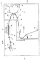
画像形成装置10は、図5に示されるように、搬送される長尺状の連帳紙Pにトナー画像を形成する画像形成部材の一例としての画像形成部12と、画像形成部12に対して連帳紙Pの搬送方向の下流側に配置され、連帳紙Pに形成されたトナー画像を加熱定着する定着部14と、定着部14に対して連帳紙Pの搬送方向の下流側に配置され、連帳紙Pに駆動力を付与する搬送部16と、画像形成部12に対して連帳紙Pの搬送方向の上流側に配置され、画像形成部12を通過する連帳紙Pに対して張力を付与し、かつ、連帳紙Pの搬送方向に対して直交する方向(主走査方向)の連帳紙Pの位置ずれを補正する送出部18と、を備えている。さらに、画像形成装置10は、連帳紙Pの搬送経路50に沿って連帳紙Pを案内する搬送ガイド48を複数備えている。
(overall structure)
As shown in FIG. 5, the
また、画像形成装置10は、装置本体の一例としての筐体22、及び筐体24を備えており、画像形成部12及び送出部18は筐体22の内部に、定着部14及び搬送部16は筐体24の内部に配置されている。
The
なお、連帳紙Pを搬送する搬送装置20は、搬送部16と送出部18とを含んで構成されている。なお、送出部18については、詳細を後述する。
The
〔画像形成部〕
画像形成部12は、図中矢印B方向に回転する円柱状の像保持体28と、像保持体28を帯電する帯電ロール30と、帯電ロール30に対して像保持体28の回転方向の下流側で帯電後の像保持体28を露光して静電潜像を形成する露光部材32と、露光部材32に対して像保持体28の回転方向の下流側で像保持体28に形成された静電潜像をトナーによりトナー画像として現像する現像部材34と、現像部材34に対して像保持体28の回転方向の下流側で像保持体28上に形成されたトナー画像を連帳紙Pの表面に転写する転写部材36と、を備えている。
(Image forming part)
The
転写部材36は、像保持体28と対向して配置され、像保持体28と転写部材36との間が、連帳紙Pにトナー画像を転写する転写位置Tとされている。
The
また、画像形成部12は、連帳紙Pが転写位置Tを通過するように、転写位置Tに対して連帳紙Pの搬送方向の上流側及び下流側に配置された側面視楕円状のガイド部材38を複数備えている。このガイド部材38は、連帳紙Pが転写位置Tを通過するように、連帳紙Pの裏面に接触している。
Further, the
〔定着部〕
定着部14は、連帳紙Pの搬送方向に対して直交する方向に沿って延び、連帳紙Pの搬送方向に並べられたフラッシュランプ40を複数備えている。このフラッシュランプ40は、連帳紙Pの表面と対向して非接触に配置されている。そして、トナー画像がフラッシュランプ40と対向する位置を通過する際に、トナー画像を連帳紙Pに定着するフラッシュランプ40が、点灯するようになっている。
[Fixing part]
The
〔搬送部〕
搬送部16は、図示せぬモータから回転力が伝達されて図中矢印C方向に回転して連帳紙Pに搬送力を付与する付与部材の一例としての駆動ロール42と、駆動ロール42の図中上側に配置され、駆動ロール42との間で連帳紙Pを挟み込むピンチロール46と、駆動ロール42の図中右側(定着部14側)に配置され、駆動ロール42に対する連帳紙Pの巻き付け量を規定する巻付けロール44と、を備えている。
[Transport section]
The
(全体構成の作用)
次に、この画像形成装置10を用いて連帳紙Pに画像を形成する画像形成動作について説明する。
(Operation of the overall configuration)
Next, an image forming operation for forming an image on the continuous paper P using the
画像形成動作の開始に伴い、駆動ロール42が回転して連帳紙Pが搬送経路50に沿って搬送される。
With the start of the image forming operation, the
一方、画像形成動作の開始に伴い画像形成部12では、像保持体28が、矢印B方向に回転し、帯電ロール30が、回転する像保持体28の表面を帯電する。さらに、露光部材32が、帯電した像保持体28を露光して像保持体28の表面に静電潜像を形成する。
On the other hand, in the
現像部材34が、像保持体28の表面に形成された静電潜像を現像してトナー画像として可視化する。さらに、転写部材36が、像保持体28の表面に形成されたトナー画像を、転写位置Tを通過する連帳紙Pの表面に転写する。
The developing
定着部14では、フラッシュランプ40が、トナー画像が転写された連帳紙Pの表面に向けて光を照射し、トナー画像を加熱してトナー画像を連帳紙Pに定着する。トナー画像が定着した連帳紙Pは、搬送部16を通過して画像形成装置10の外部へと排出される。これにより、一連の画像形成動作が終了する。
In the
(要部構成)
次に、送出部18について説明する。
(Main part configuration)
Next, the sending
送出部18は、連帳紙Pの裏面に接触して連帳紙Pに張力を付与する張力付与ロール56と、張力付与ロール56に対して連帳紙Pの搬送方向(以下「副走査方向」と記載する)の下流側に配置され、副走査方向に対して直交する方向(以下「主走査方向」と記載する)の連帳紙Pの位置ずれを補正する補正機構58と、を備えている。
The
〔補正機構〕
補正機構58は、図3、図4に示されるように、主走査方向から見て湾曲状されると共に連帳紙Pの表面が接触する湾曲面60Aが形成された湾曲板状の湾曲部材の一例としての湾曲ガイド60と、主走査方向における湾曲ガイド60の一端部に取り付けられ、連帳紙Pの縁部が突き当てられる扇状の突き当て部材の一例としてのサイドガイド64と、を備えている。この湾曲面60Aにおける副走査方向の中央側には、主走査方向に並ぶ複数の開口の一例としての矩形開口60Bが形成されている。
[Correction mechanism]
As shown in FIGS. 3 and 4, the
また、補正機構58は、夫々の矩形開口60Bから連帳紙P側(搬送経路50側)に一部が突出するように配置され、図示せぬフレーム部材に回転可能に支持される回転部材の一例としての斜行ロール62を備えている。
Further, the
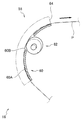
矩形開口60Bが形成された部位の湾曲面60Aに対して直交する方向から見ると(法線方向から見ると)、図2に示されるように、斜行ロール62の回転軸62Aは、主走査方向(図中矢印D方向)に対して傾斜している。この構成において、搬送される連帳紙Pの表面に斜行ロール62の外周面62Bが接触することで斜行ロール62が回転し、搬送される連帳紙Pの縁部がサイドガイド64に突き当てられるようになっている。
When viewed from a direction orthogonal to the
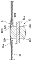
また、回転軸62Aに沿って斜行ロール62を切断すると、図1に示されるように、斜行ロール62の外周面62Bの断面形状は、回転軸方向の中央側が径方向外側に突出するように円弧状とされている。これにより、斜行ロール62の側面62Cと外周面62Bとが接する角部62Dと、連帳紙Pの表面とが接触しないようになっている。
Further, when the
(要部構成の作用)
次に、要部構成の作用について説明する。
(Effects of main components)
Next, the operation of the main configuration will be described.
画像形成装置10による画像形成動作に伴い、駆動ロール42が、回転して連帳紙Pを搬送経路50に沿って搬送する。また、張力付与ロール56が連帳紙Pに張力を付与し、張力が付与された連帳紙Pは、湾曲ガイド60の湾曲面60Aに接触しながら(押し付けられながら)搬送される。
Along with the image forming operation by the
連帳紙Pが湾曲面60Aを通過する際に、搬送される連帳紙Pの表面に斜行ロール62の外周面62Bが接触することで斜行ロール62が回転する。斜行ロール62が回転することで、搬送される連帳紙Pの縁部がサイドガイド64に突き当てられる。これにより、主走査方向における連帳紙Pの位置ずれが補正される。
When the continuous paper P passes through the
ここで、連帳紙Pの表面に外周面62Bが接触することで斜行ロール62が回転する際には、図1に示されるように、外周面62Bの断面形状が円弧状とされているため、前述したように、角部62Dと連帳紙Pの表面とが接触しない。
Here, when the
これにより、角部62Dと連帳紙Pとが接触する場合と比して、主走査方向の連帳紙Pの位置補正に起因して連帳紙Pに発生する傷が抑制される。
Thereby, as compared with the case where the
また、連帳紙Pに発生する傷を抑制されるため、画像形成装置10による出力画像の品質の低下が抑制される。
Further, since the scratches generated on the continuous paper P are suppressed, the deterioration of the output image quality by the
また、外周面62Bの断面が円弧状とされているため、例えば、外周面の断面が複数のRから構成される曲線状である場合と比して、斜行ロール62が容易に製造される。
Moreover, since the cross section of the outer
なお、本発明を特定の実施形態について詳細に説明したが、本発明はかかる実施形態に限定されるものではなく、本発明の範囲内にて他の種々の実施形態をとることが可能であることは当業者にとって明らかである。例えば、角部62Dと連帳紙Pの表面とが接触しない場合を例にとって説明したが、接触していてもよく、外周面62Bを円弧状とすることで、角部62Dと連帳紙Pの表面とが接触圧力が、斜行ロールが円柱状の場合と比して、低減していればよい。
Although the present invention has been described in detail with respect to specific embodiments, the present invention is not limited to such embodiments, and various other embodiments can be taken within the scope of the present invention. This will be apparent to those skilled in the art. For example, the case where the
また、上記実施形態では、外周面62Bの断面形状を円弧状としたが特に円弧状に限定されず、曲線状であればよい。この場合には、外周面の断面に角部が形成される場合と比して、連帳紙Pに発生する傷が抑制される。
Moreover, in the said embodiment, although the cross-sectional shape of the outer
また、上記実施形態では、外周面62Bの断面形状を円弧状としたが特に円弧状に限定されず、外周面における回転軸方向の中央側が端部側に対して径方向の外側に突出してればよい。この場合には、斜行ロールの角部が連帳紙Pの表面に接触するのが抑制される。このため、斜行ロールが円柱状である場合と比して、連帳紙Pに発生する傷が抑制される。例えば、円筒状のロールの角部にRを形成させてもよく、また、円筒状のロールの角部にチャンフャーを形成させてもよい。
In the above-described embodiment, the cross-sectional shape of the outer
なお、上記実施形態では、張力付与ロール56について具体的に説明しなかったが、張力付与ロール56に対向するように対向ロールを配置させ、この対向ロールに張力付与ロール56を用いて連帳紙Pをピンチして、連帳紙Pに張力を付与してもよい。
In the above embodiment, the
10 画像形成装置
12 画像形成部(画像形成部材の一例)
20 搬送装置
42 駆動ロール(付与部材の一例)
50 搬送経路
60 湾曲ガイド(湾曲部材の一例)
60A 湾曲面
60B 矩形開口(開口の一例)
62 斜行ロール(回転部材の一例)
62A 回転軸
62B 外周面
64 サイドガイド(突き当て部材の一例)
DESCRIPTION OF
20 Conveying
50
60A
62 Skew roll (example of rotating member)
62A
Claims (4)
連帳紙の搬送経路において前記付与部材に対して前記連帳紙の搬送方向の上流側に配置され、前記搬送方向に対して直交する直交方向から見て湾曲され連帳紙が接触する湾曲面が形成される湾曲部材と、
前記湾曲部材に対して、前記直交方向の一方側に配置され、搬送される前記連帳紙の縁部が突き当てられる突き当て部材と、
前記湾曲面に形成された複数の開口から前記搬送経路側に一部が突出するように前記直交方向に並んで複数配置され、夫々の回転軸が前記直交方向に対して傾斜し、外周面で前記連帳紙と接触しながら回転し、前記縁部を前記突き当て部材に突き当てると共に、前記外周面における回転軸方向の中央側が端部側に対して径方向の外側に突出している回転部材と、
を備える搬送装置。 An imparting member for imparting a conveying force to the continuous paper;
A curved surface that is arranged on the upstream side in the conveyance direction of the continuous paper with respect to the application member in the conveyance path of the continuous paper, and is curved as viewed from an orthogonal direction orthogonal to the conveyance direction and contacts the continuous paper A curved member formed with:
An abutting member that is disposed on one side in the orthogonal direction with respect to the bending member, and against which an edge of the continuous paper to be conveyed is abutted,
A plurality of arrangements are arranged in the orthogonal direction so that a part protrudes from the plurality of openings formed in the curved surface to the conveyance path side, and each rotation axis is inclined with respect to the orthogonal direction, A rotating member that rotates while in contact with the continuous paper, abuts the edge portion against the abutting member, and a central side of the outer peripheral surface in the rotational axis direction projects radially outward with respect to the end side. When,
A transport apparatus comprising:
前記搬送装置に備えられた搬送経路において、前記湾曲部材に対して前記連帳紙の搬送方向の下流側に配置され、搬送される前記連帳紙に画像を形成する画像形成部材と、
を備える画像形成装置。 A transport apparatus according to any one of claims 1 to 3,
An image forming member that is disposed downstream of the curved member in the transport direction of the continuous paper and forms an image on the transported continuous paper in the transport path provided in the transport device;
An image forming apparatus comprising:
Priority Applications (1)
| Application Number | Priority Date | Filing Date | Title |
|---|---|---|---|
| JP2012160460A JP5935564B2 (en) | 2012-07-19 | 2012-07-19 | Conveying device, image forming apparatus |
Applications Claiming Priority (1)
| Application Number | Priority Date | Filing Date | Title |
|---|---|---|---|
| JP2012160460A JP5935564B2 (en) | 2012-07-19 | 2012-07-19 | Conveying device, image forming apparatus |
Publications (3)
| Publication Number | Publication Date |
|---|---|
| JP2014019549A JP2014019549A (en) | 2014-02-03 |
| JP2014019549A5 JP2014019549A5 (en) | 2015-05-07 |
| JP5935564B2 true JP5935564B2 (en) | 2016-06-15 |
Family
ID=50194867
Family Applications (1)
| Application Number | Title | Priority Date | Filing Date |
|---|---|---|---|
| JP2012160460A Active JP5935564B2 (en) | 2012-07-19 | 2012-07-19 | Conveying device, image forming apparatus |
Country Status (1)
| Country | Link |
|---|---|
| JP (1) | JP5935564B2 (en) |
Family Cites Families (3)
| Publication number | Priority date | Publication date | Assignee | Title |
|---|---|---|---|---|
| JPS58139944A (en) * | 1982-02-13 | 1983-08-19 | Canon Inc | Paper feeding device |
| JPH06156827A (en) * | 1992-11-13 | 1994-06-03 | Sony Corp | Taking-up of long body and device therefor |
| JP4396462B2 (en) * | 2004-09-21 | 2010-01-13 | 富士ゼロックス株式会社 | Web guide mechanism and image forming apparatus |
-
2012
- 2012-07-19 JP JP2012160460A patent/JP5935564B2/en active Active
Also Published As
| Publication number | Publication date |
|---|---|
| JP2014019549A (en) | 2014-02-03 |
Similar Documents
| Publication | Publication Date | Title |
|---|---|---|
| JP5804735B2 (en) | Sheet conveying apparatus and image forming apparatus | |
| JP6098490B2 (en) | Image forming apparatus | |
| JP5111561B2 (en) | Drive mechanism and image forming apparatus provided with drive mechanism | |
| US9334931B2 (en) | Belt drive mechanism, belt drive apparatus, and pulley | |
| JP6330728B2 (en) | Image forming apparatus | |
| JP5935564B2 (en) | Conveying device, image forming apparatus | |
| JP2008230733A (en) | Paper sheet conveying device and image forming device | |
| JP2008107644A (en) | Automatic meandering correction mechanism and image forming apparatus with the same | |
| JP5765890B2 (en) | Sheet conveying apparatus and image forming apparatus | |
| JP5811238B2 (en) | Document feeder, image reading apparatus, and image forming apparatus | |
| JP5264207B2 (en) | Photosensitive drum and image forming apparatus | |
| JP5393223B2 (en) | Image forming apparatus and sheet conveying apparatus | |
| TWI566952B (en) | Transferring Roller,? Transmission Assembly, and Office Machine Using the same | |
| JP5641893B2 (en) | Paper conveying apparatus and image forming apparatus | |
| JP2017218293A (en) | Sheet conveyance device and image formation apparatus | |
| JP6478594B2 (en) | Sheet conveying apparatus and image forming apparatus | |
| JP2015081170A (en) | Transport mechanism, and image forming apparatus | |
| JP2017065916A (en) | Sheet transportation device and image formation device | |
| JP4277319B2 (en) | Image forming apparatus | |
| JP5935727B2 (en) | Sheet material conveyance path and image forming apparatus | |
| JP3567744B2 (en) | Paper feeder | |
| JP2007223761A (en) | Paper sheet conveyance member, paper sheet conveyance device, and image forming device | |
| JPH07285705A (en) | Paper feeding device | |
| JP2015093777A (en) | Image formation device | |
| JP2014046994A (en) | Sheet conveyance device and image forming apparatus |
Legal Events
| Date | Code | Title | Description |
|---|---|---|---|
| A621 | Written request for application examination |
Free format text: JAPANESE INTERMEDIATE CODE: A621 Effective date: 20150306 |
|
| A521 | Written amendment |
Free format text: JAPANESE INTERMEDIATE CODE: A523 Effective date: 20150323 |
|
| A977 | Report on retrieval |
Free format text: JAPANESE INTERMEDIATE CODE: A971007 Effective date: 20160114 |
|
| A131 | Notification of reasons for refusal |
Free format text: JAPANESE INTERMEDIATE CODE: A131 Effective date: 20160119 |
|
| A521 | Written amendment |
Free format text: JAPANESE INTERMEDIATE CODE: A523 Effective date: 20160310 |
|
| TRDD | Decision of grant or rejection written | ||
| A01 | Written decision to grant a patent or to grant a registration (utility model) |
Free format text: JAPANESE INTERMEDIATE CODE: A01 Effective date: 20160412 |
|
| A61 | First payment of annual fees (during grant procedure) |
Free format text: JAPANESE INTERMEDIATE CODE: A61 Effective date: 20160425 |
|
| R150 | Certificate of patent or registration of utility model |
Ref document number: 5935564 Country of ref document: JP Free format text: JAPANESE INTERMEDIATE CODE: R150 |
|
| S533 | Written request for registration of change of name |
Free format text: JAPANESE INTERMEDIATE CODE: R313533 |
|
| R350 | Written notification of registration of transfer |
Free format text: JAPANESE INTERMEDIATE CODE: R350 |