JP2015194663A - Transfer device and image forming apparatus - Google Patents
Transfer device and image forming apparatus Download PDFInfo
- Publication number
- JP2015194663A JP2015194663A JP2014110082A JP2014110082A JP2015194663A JP 2015194663 A JP2015194663 A JP 2015194663A JP 2014110082 A JP2014110082 A JP 2014110082A JP 2014110082 A JP2014110082 A JP 2014110082A JP 2015194663 A JP2015194663 A JP 2015194663A
- Authority
- JP
- Japan
- Prior art keywords
- transfer
- bias
- secondary transfer
- image
- roller
- Prior art date
- Legal status (The legal status is an assumption and is not a legal conclusion. Google has not performed a legal analysis and makes no representation as to the accuracy of the status listed.)
- Pending
Links
Images


Abstract
Description
本発明は、プリンタ、ファクシミリ、複写機などの画像形成装置に用いられる転写装置、及び、その転写装置を備えた画像形成装置に関するものである。 The present invention relates to a transfer device used in an image forming apparatus such as a printer, a facsimile machine, and a copying machine, and an image forming apparatus including the transfer device.
従来、画像形成装置の転写装置として、像担持体に当接するニップ形成部材により転写ニップを形成して記録媒体を挟み込み、転写バイアス電源より出力した転写バイアスを転写ニップに印加して、像担持体上のトナー像を記録媒体に転写するものが知られている。その一例として、複数の感光体上に形成したトナー像を中間転写ベルト上に順次一次転写した重合わせトナー像を、記録材に二次転写する二次転写装置が知られている。 2. Description of the Related Art Conventionally, as a transfer device of an image forming apparatus, a transfer nip is formed by a nip forming member abutting on an image carrier to sandwich a recording medium, and a transfer bias output from a transfer bias power source is applied to the transfer nip. There is known one that transfers the above toner image to a recording medium. As an example, there is known a secondary transfer device that secondarily transfers a superimposed toner image obtained by sequentially transferring toner images formed on a plurality of photoconductors onto an intermediate transfer belt to a recording material.
二次転写装置では、ニップ形成部材として、像担持体としての中間転写ベルト表面に当接する二次転写ローラと、二次転写ローラと対向して中間転写ベルト裏面に当接する二次転写対向ローラとを設けている。そして、二次転写ローラと二次転写対向ローラとの間に中間転写ベルトを挟み込んで転写ニップを形成する。 In the secondary transfer device, as a nip forming member, a secondary transfer roller that abuts on the surface of the intermediate transfer belt as an image carrier, and a secondary transfer counter roller that abuts against the secondary transfer roller and abuts on the back surface of the intermediate transfer belt. Is provided. Then, an intermediate transfer belt is sandwiched between the secondary transfer roller and the secondary transfer counter roller to form a transfer nip.
この二次転写対向ローラまたは二次転写ローラの何れか一方を転写バイアス電源に接続して出力された直流電圧からなる転写バイアスを印加し、他方をアースに接続する。これにより、二次転写対向ローラと二次転写ローラとの間に、トナー像を二次転写対向ローラ側から二次転写ローラ側に静電移動させる転写電界が形成される。そして、中間転写ベルト上のトナー像に同期させるタイミングで転写ニップ内に送り込んだ記録媒体に対して、前記転写電界の作用により、中間転写ベルト上のトナー像を二次転写する。 Either one of the secondary transfer counter roller or the secondary transfer roller is connected to a transfer bias power source, a transfer bias composed of a DC voltage outputted is applied, and the other is connected to the ground. Thereby, a transfer electric field for electrostatically moving the toner image from the secondary transfer counter roller side to the secondary transfer roller side is formed between the secondary transfer counter roller and the secondary transfer roller. Then, the toner image on the intermediate transfer belt is secondarily transferred to the recording medium fed into the transfer nip at a timing synchronized with the toner image on the intermediate transfer belt by the action of the transfer electric field.
このような画像形成装置において、転写バイアス電源によって二次転写ローラまたは二次転写対向ローラに印加する転写バイアスを、定電流制御することが知られている。このように転写バイアスを定電流制御した場合は、中間転写ベルトや二転写ローラなどの電気抵抗が温度湿度環境などで変動しても、それにしたがって印加電圧が変化するため、転写ニップでの転写電界としては安定し、安定した転写性を得ることができる。 In such an image forming apparatus, it is known that the transfer bias applied to the secondary transfer roller or the secondary transfer counter roller by the transfer bias power source is controlled at a constant current. In this way, when the transfer bias is controlled at a constant current, even if the electrical resistance of the intermediate transfer belt, the two transfer rollers, etc. fluctuates in a temperature and humidity environment, the applied voltage changes accordingly. As a result, stable transferability can be obtained.
かかる構成において、記録媒体として、和紙のような表面が凹凸に富んだものを用いると、表面の凹凸にならった濃淡パターン(濃度ムラ)を画像中に発生させ易くなる。この濃淡パターン(濃度ムラ)は、紙表面における凹部に対して十分量のトナーが転写されずに、凹部の画像濃度が凸部よりも薄くなることによって生じるものである。 In such a configuration, if a recording medium such as Japanese paper having a surface with a lot of unevenness is used as the recording medium, it becomes easy to generate a light and shade pattern (density unevenness) in the image. This light / dark pattern (density unevenness) is caused by the fact that a sufficient amount of toner is not transferred to the concave portion on the paper surface, and the image density of the concave portion becomes thinner than the convex portion.
そこで、特許文献1に記載の画像形成装置が備える転写装置においては、直流電源と交流電源とを接続させた転写バイアス電源を用いて、直流電圧に交流電圧を重畳させた転写バイアスを印加するようになっている。このような転写バイアスを用いることで、記録媒体表面の凹部と像担持体との間でトナーが往復運動し、記録媒体表面の凹部にトナーが接触することができるようになり、記録媒体表面の凹部へのトナーの転写不良を抑制できるとされている。
Therefore, in the transfer device provided in the image forming apparatus described in
直流電源と交流電源とを接続させた転写バイアス電源を用いて、直流電圧に交流電圧を重畳させた転写バイアスを印加する場合には、転写バイアスの直流成分が交流電源の基板を経由して出力される。 When applying a transfer bias in which an AC voltage is superimposed on a DC voltage using a transfer bias power source in which a DC power source and an AC power source are connected, the DC component of the transfer bias is output via the substrate of the AC power source. Is done.
本願発明者が鋭意研究を重ねた結果、直流電源と交流電源とを接続した転写バイアス電源によって転写バイアスを定電流制御で印加した場合に、次のような問題が生じることがわかった。 As a result of intensive studies by the inventor of the present application, it has been found that the following problems occur when a transfer bias is applied by constant current control by a transfer bias power source in which a DC power source and an AC power source are connected.
すなわち、交流電源の基板内のコンデンサ回路の影響によって、直流電源だけを用いて直流電圧を出力した場合よりも、転写バイアスの直流成分の出力応答性が遅くなり、転写に必要な目標電圧までの立ち上がり時間が長くなる傾向にあった。そのため、画像先端部において必要な転写バイアスが確保できず、画像先端部の画像濃度の希薄化が発生し転写不良となってしまう。 That is, due to the influence of the capacitor circuit in the substrate of the AC power supply, the output responsiveness of the DC component of the transfer bias becomes slower than when the DC voltage is output using only the DC power supply, and the target voltage required for transfer is reduced. The rise time tended to be longer. For this reason, a necessary transfer bias cannot be secured at the leading edge of the image, and the image density at the leading edge of the image is diluted, resulting in a transfer failure.
本願出願人は、直流電源と交流電源とが電気的に接続された転写バイアス電源が出力する転写バイアスの直流成分を、定電圧制御で立ち上げた後、中間転写ベルト上のトナー像が記録媒体に転写される前に定電流制御に切り替える転写装置の開発を行っている。 The applicant of the present application has started up a DC component of a transfer bias output from a transfer bias power source in which a DC power source and an AC power source are electrically connected by constant voltage control, and then the toner image on the intermediate transfer belt is recorded on the recording medium. We are developing a transfer device that switches to constant current control before it is transferred.
この転写装置のように、転写バイアス電源が出力する転写バイアスの直流成分を、定電圧制御で立ち上げることで、当該直流成分を定電流制御で立ち上げる場合よりも、急勾配で目標電圧まで立ち上げることが可能となり、立ち上がり時間を短くすることができる。 As in this transfer device, the DC component of the transfer bias output from the transfer bias power supply is raised by constant voltage control, so that the DC component rises to a target voltage at a steep slope compared to the case where the DC component is raised by constant current control. The rise time can be shortened.
また、この転写装置では、転写バイアス電源が出力する転写バイアスの直流成分の最大出力値を目指して、予め設定された立ち上げ時間だけ前記直流成分の出力を定電圧制御で行うことで、目標電圧が得られるようにしている。 Further, in this transfer apparatus, aiming at the maximum output value of the DC component of the transfer bias output from the transfer bias power source, the DC component is output by constant voltage control for a preset start-up time, thereby achieving the target voltage. Is to be obtained.
これにより、目標電圧までの立ち上がり時間の遅れによる転写バイアス不足によって、画像先端部の濃度の希薄化が生じてしまうのを抑制している。 As a result, it is possible to prevent the density at the front end of the image from being diluted due to insufficient transfer bias due to a delay in the rise time to the target voltage.
また、中間転写ベルト上のトナー像を記録媒体に転写するときには、定電流制御で転写バイアスを印加する。これにより、中間転写ベルトや二次転写ローラなどの電気抵抗が温度湿度環境などで変動しても、上述したように転写ニップでの転写電界を安定させて、安定した転写性を得ることができる。 Further, when transferring the toner image on the intermediate transfer belt to a recording medium, a transfer bias is applied by constant current control. As a result, the transfer electric field at the transfer nip can be stabilized and stable transfer performance can be obtained even if the electrical resistance of the intermediate transfer belt, the secondary transfer roller or the like fluctuates due to the temperature and humidity environment. .
しかしながら、温度や湿度などの環境変動に起因した中間転写ベルトや二次転写ローラなどの抵抗の変動などにより、前記直流成分の立ち上がりの勾配が変化する。そのため、立ち上げ開始時から同じ立ち上げ時間だけ経過したときの電圧値にばらつきが生じ、目標電圧が得られなくなるといった問題が生じる。 However, the rising slope of the DC component changes due to resistance fluctuations of the intermediate transfer belt, the secondary transfer roller, and the like caused by environmental fluctuations such as temperature and humidity. For this reason, there arises a problem that the voltage value when the same rise time has elapsed from the start of the rise varies and the target voltage cannot be obtained.
本発明は以上の問題点に鑑みなされたものであり、その目的は、直流電源と交流電源とが電気的に接続された転写バイアス電源を用いた場合に、転写不良が生じるのを抑制できる転写装置、及び、その転写装置を備えた画像形成装置を提供することである。 The present invention has been made in view of the above problems, and an object of the present invention is to provide a transfer that can suppress the occurrence of transfer failure when a transfer bias power supply in which a DC power supply and an AC power supply are electrically connected is used. And an image forming apparatus including the transfer device.
上記目的を達成するために、請求項1の発明は、像担持体に当接して転写ニップを形成するためのニップ形成部材と、直流電源と交流電源とが電気的に接続されており、転写バイアスを出力する転写バイアス電源とを備え、前記転写バイアス電源が出力する前記転写バイアスにより、前記像担持体上のトナー像を前記転写ニップ内に挟み込んだ記録媒体へ転写する転写装置において、前記転写バイアス電源は、前記転写バイアスの直流成分を、予め設定された目標電圧となるように定電圧制御で立ち上げた後、前記像担持体上のトナー像が記録媒体に転写される前に予め設定された目標電流となるよう定電流制御に切り替えることを特徴とするものである。 In order to achieve the above object, according to the first aspect of the present invention, a nip forming member for forming a transfer nip in contact with an image carrier is electrically connected to a DC power source and an AC power source. A transfer bias power supply for outputting a bias, wherein the transfer bias output by the transfer bias power supply transfers a toner image on the image carrier to a recording medium sandwiched in the transfer nip. The bias power supply is set in advance before the toner image on the image carrier is transferred to the recording medium after the DC component of the transfer bias is raised by constant voltage control so as to be a preset target voltage. It is characterized by switching to constant current control so that it becomes the set target current.
以上、本発明によれば、直流電源と交流電源とが電気的に接続された転写バイアス電源を用いた場合に、転写不良が生じるのを抑制できるという優れた効果がある。 As described above, according to the present invention, when a transfer bias power source in which a DC power source and an AC power source are electrically connected is used, there is an excellent effect that occurrence of transfer failure can be suppressed.
[実施形態1]
以下、図面により本発明の実施形態1について説明する。
図2は、本実施形態に係る画像形成装置であるプリンタの概略構成図である。
[Embodiment 1]
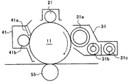
FIG. 2 is a schematic configuration diagram of a printer that is an image forming apparatus according to the present embodiment.
このプリンタは、中間転写体としての無端状のベルト部材である中間転写ベルト51を有している。また、中間転写ベルト51の上部走行辺に沿って、イエロー(Y)、マゼンタ(M)、シアン(C)、ブラック(K)の各色トナー画像を形成するための4つの画像形成ユニット1Y,1M,1C,1Kが並設され、タンデム作像部を構成している。
This printer has an
各画像形成ユニット1Y,1M,1C,1Kは、扱うトナーの色が異なるのみで構成は同一であるため、図3を参照して一つの画像形成ユニット1についてのみ説明する。なお、この際、各色を示す添え字(Y,M,C,K)は適宜省略する。
Since the image forming units 1Y, 1M, 1C, and 1K have the same configuration except for the color of the toner to be handled, only one
図3に示すように、画像形成ユニット1は、像担持体としての感光体ドラム11、帯電装置21、現像装置31、クリーニング装置41などを備えている。本実施形態では、各画像形成ユニット1Y,1M,1C,1Kは、プリンタ本体に対して脱着可能に設けられている。
As shown in FIG. 3, the
なお、帯電装置21は、感光体ドラム11の表面を帯電ローラによって帯電する帯電手段である。また、現像装置31は、感光体ドラム11上の潜像を、トナーを含む現像剤によって現像して可視化する現像手段である。また、クリーニング装置41は、感光体ドラム表面をクリーニングするクリーニング手段である。
The charging
感光体ドラム11は、ドラム基体の表面上に有機感光層が形成された外径60[mm]程度のドラム形状のものであり、図示しない駆動手段によって図中時計回り方向に回転駆動される。
The
帯電装置21は、帯電バイアスが印加される帯電ローラを感光体ドラム11に接触あるいは近接させながら、帯電ローラと感光体ドラム11との間に放電を発生させることで、感光体ドラム表面を一様帯電せしめる。
The charging
本実施形態では、トナーの正規帯電極性と同じマイナス極性に、感光体ドラム表面を帯電装置21により一様帯電せしめる。帯電バイアスとしては、直流電圧に交流電圧を重畳したものを採用している。なお、帯電ローラを用いる方式に変えて、帯電チャージャによる方式を採用しても良い。
In this embodiment, the surface of the photosensitive drum is uniformly charged by the charging
現像装置31は、トナーとキャリアとを含む2成分現像剤が収容される収容容器内に、現像剤担持体としての現像スリーブ31a及び現像剤を攪拌しながら搬送する攪拌部材としての2本のスクリュー部材31b,31cを備えている。なお、現像装置31としては、トナーを含む1成分現像剤を用いる現像装置を採用することも可能である。
The developing
クリーニング装置41は、クリーニングブレード41aと、クリーニングブラシローラ41bとを備えている。
The cleaning device 41 includes a
クリーニングブレード41aは、感光体ドラム11の回転方向に対してカウンター方向から感光体ドラム表面と当接している。また、クリーニングブラシローラ41bは、感光体ドラム11の回転方向とは逆方向に回転しながら感光体ドラム表面と接触している。そして、クリーニングブレード41aとクリーニングブラシローラ41bとにより、感光体ドラム表面をクリーニングする。
The
画像形成ユニット1Y,1M,1C,1Kの上方には、帯電装置21により帯電せしめられた感光体ドラム表面に潜像を書き込む、潜像書込手段たる光書込ユニット80が配設されている。
Above the image forming units 1Y, 1M, 1C, and 1K, an
この光書込ユニット80は、パーソナルコンピュータ等の外部機器から送られてくる画像情報に基づいて、レーザーダイオードから発したレーザー光により、感光体ドラム11Y,11M,11C,11Kの表面を光走査する。
The
この光走査により、感光体ドラム11Y,11M,11C,11Kの表面上に、Y,M,C,K用の静電潜像が形成される。具体的には、感光体ドラム11の一様帯電した表面の全域のうち、レーザー光が照射された箇所は、電位を減衰せしめる。これにより、レーザー照射箇所の電位が、それ以外の箇所(地肌部)の電位よりも小さくなり、その結果、静電潜像となる。
By this optical scanning, electrostatic latent images for Y, M, C, and K are formed on the surfaces of the photosensitive drums 11Y, 11M, 11C, and 11K. Specifically, in the entire area of the uniformly charged surface of the
なお、光書込ユニット80は、光源から発したレーザー光Lを、図示しないポリゴンモータによって回転駆動したポリゴンミラーで主走査方向に偏光せしめながら、複数の光学レンズやミラーを介して感光体ドラム表面に照射するものである。また、LEDアレイの複数のLEDから発したLED光によって、光書込を行うものを採用してもよい。
The
画像形成ユニット1Y,1M,1C,1Kの下方には、無端状の中間転写ベルト51を張架しながら図中反時計回り方向に無端移動せしめる転写装置としての転写ユニット50が配設されている。
Below the image forming units 1Y, 1M, 1C, and 1K, a
転写ユニット50は、中間転写ベルト51の他に、駆動ローラ52、二次転写対向ローラ53、クリーニングバックアップローラ54、4つの一次転写ローラ55、二次転写ローラ56、及び、ベルトクリーニング装置57などを有している。
In addition to the
中間転写ベルト51は、そのループ内側に配設された駆動ローラ52、二次転写対向ローラ53、クリーニングバックアップローラ54、及び、4つの一次転写ローラ55Y,55M,55C,55Kによって張架されている。そして、図示しない駆動手段によって図中反時計回り方向に回転駆動される駆動ローラ52の回転力により、中間転写ベルト51は図中反時計回り方向に無端移動せしめられる。
The
中間転写ベルト51としては、次のような特性を有するものを用いている。すなわち、厚みは20[μm]〜200[μm]、好ましくは60[μm]程度である。
As the
表面抵抗は、9.0〜13.0[LogΩ/cm2]、好ましくは10.0〜12.0[LogΩ/cm2]である。なお、測定方法としては、三菱化学製ハイレスタ−UP MCP HT45、HRSプローブにて、印加電圧500[V]、10[sec]値の条件で測定する。 The surface resistance is 9.0 to 13.0 [LogΩ / cm 2 ], preferably 10.0 to 12.0 [LogΩ / cm 2 ]. In addition, as a measuring method, it measures on the conditions of the applied voltage 500 [V] and 10 [sec] value with Mitsubishi Chemical's Hiresta UP MCP HT45, HRS probe.
また、体積抵抗率は6.0〜13.0[LogΩcm]、好ましくは7.5〜12.5[LogΩcm]、より好ましくは約9.0[LogΩcm]程度である。なお、測定方法としては、三菱化学製ハイレスタ−UP MCP HT45、HRSプローブにて、印加電圧100[V]、10[sec]値の条件で測定する。 The volume resistivity is about 6.0 to 13.0 [Log Ωcm], preferably about 7.5 to 12.5 [Log Ωcm], and more preferably about 9.0 [Log Ωcm]. In addition, as a measuring method, it measures on the conditions of the applied voltage of 100 [V] and 10 [sec] value with Mitsubishi Chemical's Hiresta UP MCP HT45, HRS probe.
また、材料は、PI(ポリイミド)、PVDF(フッ化ビニルデン)、ETFE(エチレン−四フッ化エチレン共重合体)、PC(ポリカーボネート)等を単層または複数層に構成したものを使用することも可能である。 The material may be a single layer or multiple layers of PI (polyimide), PVDF (vinylidene fluoride), ETFE (ethylene-tetrafluoroethylene copolymer), PC (polycarbonate), etc. Is possible.
なお、必要に応じて中間転写ベルト51の表面に、離型層をコートしても良い。コートに用いる材料としては、次のものが挙げられるが、これらに限定されるものではない。例えば、ETFE(エチレン−四フッ化エチレン共重合体)、PTFE(ポリ四フッ化エチレン)、PVDF(フッ化ビニルデン)、PEA(パーフルオロアルコキシフッ素樹脂)、FEP(四フッ化エチレン−六フッ化プロピレン共重合体)、PVF(フッ化ビニル)等のフッ素樹脂が使用できる。
Note that a release layer may be coated on the surface of the
ベルト製造方法としては、注型法や遠心成形法などがあり、必要に応じてその表面を研磨しても良い。 Examples of the belt manufacturing method include a casting method and a centrifugal molding method, and the surface thereof may be polished if necessary.
また、ベース層、弾性層及びコート層の3層構造となっている無端状のベルト部材を用いても良い。 Further, an endless belt member having a three-layer structure of a base layer, an elastic layer, and a coat layer may be used.
3層構造のベルト部材の場合、ベース層は、例えば伸びの少ないフッ素系樹脂や、伸びの大きなゴム材料に帆布などの伸びにくい材料を組み合わせた材料で構成する。また、弾性層は、例えばフッ素系ゴムやアクリロニトリル−ブタジエン共重合ゴムなどで構成され、ベース層の上に形成する。また、コート層は、弾性層の表面に、例えばフッ素系樹脂がコーティングされることで形成する。 In the case of a belt member having a three-layer structure, the base layer is made of a material obtained by combining, for example, a fluorine-based resin having a small elongation or a rubber material having a large elongation with a material that is difficult to stretch, such as canvas. The elastic layer is made of, for example, fluorine rubber or acrylonitrile-butadiene copolymer rubber, and is formed on the base layer. The coat layer is formed by coating the surface of the elastic layer with, for example, a fluorine resin.
なお、中間転写ベルト51の抵抗率は、カーボンブラック等の導電性材料をベルト部材中に分散させて調整している。
The resistivity of the
一次転写ローラ55Y,55M,55C,55Kは、無端移動せしめられる中間転写ベルト51を、感光体ドラム11Y,11M,11C,11Kとの間に挟み込んでいる。これにより、中間転写ベルト51のおもて面と、感光体ドラム11Y,11M,11C,11Kとが当接するY,M,C,K用の一次転写ニップが形成されている。
The
一次転写ローラ55Y,55M,55C,55Kには、図示しない転写バイアス電源によってそれぞれ一次転写バイアスが印加される。これにより、感光体ドラム11Y,11M,11C,11K上の各色トナー像と、各一次転写ローラ55との間に転写電界が形成され、転写電界やニップ圧の作用により、各感光体ドラム11上から中間転写ベルト51上にトナー像が一次転写される。
A primary transfer bias is applied to the
そして、Yトナー像、Mトナー像、Cトナー像及びKトナー像が、中間転写ベルト51上で順次重ね合わされて一次転写されることにより、中間転写ベルト51上には4色重ね合わせトナー像が形成される。
Then, the Y toner image, the M toner image, the C toner image, and the K toner image are sequentially superimposed and primarily transferred on the
モノクロ画像を形成する場合には、転写ユニット50におけるY,M,C用の一次転写ローラ55Y,55M,55Cを支持している図示しない支持板を移動させて、一次転写ローラ55Y,55M,55Cを、感光体ドラム11Y,11M,11Cから遠ざける。
In the case of forming a monochrome image, a support plate (not shown) supporting the
これにより、中間転写ベルト51のおもて面を感光体ドラム11Y,M,Cから引き離して、中間転写ベルト51を感光体ドラム11Kだけに当接させる。
As a result, the front surface of the
この状態で、4つの画像形成ユニット1Y,1M,1C,1Kのうち、画像形成ユニット1Kだけを駆動して、Kトナー像を感光体ドラム11K上に形成する。 In this state, among the four image forming units 1Y, 1M, 1C, and 1K, only the image forming unit 1K is driven to form a K toner image on the photosensitive drum 11K.
一次転写ローラ55は、金属製の芯金と、これの表面上に固定された導電性のスポンジ層とを具備している弾性ローラからなり、本実施形態では次のような特性を有している。
The
ローラ外形は16[mm]であり、芯金の径は10[mm]である。体積抵抗は6.0〜8.0[LogΩcm]、好ましくは7.0〜8.0[LogΩcm]である。 The roller outer shape is 16 [mm], and the diameter of the cored bar is 10 [mm]. The volume resistance is 6.0 to 8.0 [Log Ωcm], preferably 7.0 to 8.0 [Log Ωcm].
なお、一次転写ローラ55の体積抵抗は回転測定によるもので、10[N]/片側の加重を加え、一次転写ローラ軸に1[kV]のバイアスを印加し、1分の測定間に一次転写ローラ55を1回転させながら抵抗値を測定し、その平均値を体積抵抗とした。
The volume resistance of the
また、オームの法則(R=V/I)に基づいて算出したスポンジ層の抵抗Rは、1E6[Ω]〜1E9[Ω]、好ましくは約3E7[Ω]である。 The resistance R of the sponge layer calculated based on Ohm's law (R = V / I) is 1E6 [Ω] to 1E9 [Ω], preferably about 3E7 [Ω].
このような一次転写ローラ55に対して、一次転写バイアスを定電流制御で印加する。なお、一次転写ローラ55に代えて、転写チャージャや転写ブラシなどを用いた一次転写手段を採用してもよい。
A primary transfer bias is applied to such a
転写ユニット50の二次転写ローラ56は、中間転写ベルト51のループ外側に配設されており、ループ内側の二次転写対向ローラ53との間に中間転写ベルト51を挟み込んでいる。これにより、中間転写ベルト51のおもて面と、二次転写ローラ56とが当接する二次転写ニップが形成されている。
The
なお、転写ユニット50において、二次転写ローラ56と二次転写対向ローラ53とで中間転写ベルト51が挟み込まれた箇所が、中間転写ベルト51上から記録紙P上にトナー像が転写される二次転写部である。
In the
二次転写ローラ56は電気的に接地されているのに対し、二次転写対向ローラ53には二次転写バイアス電源200が接続され二次転写バイアス電源200によって二次転写バイアスが印加される。これにより、二次転写対向ローラ53と二次転写ローラ56との間に、トナーを二次転写対向ローラ53側から二次転写ローラ56側に向けて静電移動させる二次転写電界が形成される。
While the
なお、二次転写ローラ56に転写バイアス電源200が接続され、二次転写対向ローラ53が電気的に接地される構成としても良い。
The
転写ユニット50の下方には、記録紙Pを複数枚重ねた紙束の状態で収容している給紙カセット100が配設されている。この給紙カセット100は、紙束の一番上の記録紙Pに給紙ローラ101を当接させており、これを所定のタイミングで回転駆動させることで、その記録紙Pを給紙路に向けて送り出す。
Below the
給紙路の末端付近には、レジストローラ対102が配設されている。このレジストローラ対102は、給紙カセット100から送り出された記録紙Pをローラ間に挟み込むと、すぐに両ローラの回転を停止させる。
A
そして、挟み込んだ記録紙Pを二次転写ニップ内で中間転写ベルト51上のトナー像に同期させ得るタイミングで、レジストローラ対102の両ローラの回転駆動を再開して、記録紙Pを二次転写ニップに向けて送り出す。
Then, at a timing at which the sandwiched recording paper P can be synchronized with the toner image on the
二次転写ニップで記録紙Pに密着せしめられた中間転写ベルト51上のトナー像は、二次転写電界やニップ圧の作用によって記録紙P上に一括二次転写される。
The toner image on the
このようにして表面にフルカラートナー像またはモノクロトナー像が形成された記録紙Pは、二次転写ニップを通過すると、二次転写ローラ56や中間転写ベルト51から曲率分離する。
The recording paper P having the full-color toner image or the monochrome toner image formed on the surface in this way is separated from the
二次転写対向ローラ53は、ステンレス鋼やアルミニウム等からなる芯金に抵抗層を積層したものである。
The secondary
抵抗層は、ポリカーボネートやフッ素系ゴムやシリコン系ゴム等に、カーボンや金属錯体等の導電粒子を分散させたもの、あるいは、NBRやEPDM等のゴム、NBR/ECO共重合のゴム、ポリウレタンの半導電性ゴム等よりなる。その体積抵抗は、6.0〜12.0[LogΩcm]、望ましくは7.0〜9.0[LogΩcm]である。 The resistance layer is made by dispersing conductive particles such as carbon or metal complex in polycarbonate, fluorine rubber, silicon rubber or the like, or rubber such as NBR or EPDM, rubber of NBR / ECO copolymer, polyurethane Made of conductive rubber or the like. The volume resistance is 6.0 to 12.0 [Log Ωcm], preferably 7.0 to 9.0 [Log Ωcm].
また、硬度20度〜50度の発泡タイプでも、ゴム硬度30度〜60度のゴムタイプでもよいが、中間転写ベルト51を介して二次転写ローラ56と接触するので、小さな接触圧力でも非接触部分が生じないスポンジタイプが望ましい。これは、中間転写ベルト51と二次転写対向ローラ53との接触圧力が大きいほど、文字や細線の中抜けが生じ易いので、これを防止するためである。
Further, a foam type having a hardness of 20 degrees to 50 degrees or a rubber type having a rubber hardness of 30 degrees to 60 degrees may be used. However, since the contact is made with the
また、二次転写ローラ56は、ステンレス鋼やアルミニウム等からなる芯金上に、導電性ゴム等からなる抵抗層と表層とを積層して形成してある。
The
本実施形態では、二次転写ローラ56の外径は20[mm]であり、芯金は直径16[mm]のステンレス鋼である。抵抗層は、NBR/ECOの共重合体よりなる硬度40〜60度[JIS−A]のゴムである。
In this embodiment, the outer diameter of the
表層は、含フッ素ウレタンエラストマーからなり、その厚みは8〜24[μm]が望ましい。その理由としては、ローラの表層は塗装工程により製造されることが多いので、表層の厚みが8[μm]以下では、塗布ムラによる抵抗ムラの影響が大きく、抵抗の低い箇所でリークが発生する可能性があり好ましくない。また、ローラ表面にシワが生じて、表層がひび割れるという問題も生じ易い。 The surface layer is made of a fluorine-containing urethane elastomer, and the thickness is desirably 8 to 24 [μm]. The reason is that the surface layer of the roller is often manufactured by a coating process. Therefore, when the surface layer thickness is 8 [μm] or less, the influence of the resistance unevenness due to the uneven coating is large, and a leak occurs at a location where the resistance is low. There is a possibility that it is not preferable. In addition, wrinkles are generated on the roller surface and the surface layer is liable to crack.
一方、表層の厚みが24[μm]以上に厚くなると抵抗が高くなり、体積抵抗率が高い場合には、二次転写対向ローラ53の芯金に定電流を印加したときの電圧が上昇することがあり、定電流電源の電圧可変範囲を超えるので目標の電流以下の電流になる。また、電圧可変範囲が十分高い範囲の場合には、定電流電源から二次転写対向ローラ53の芯金までの高圧経路や、二次転写対向ローラ53の芯金が高電圧になることによるリークが発生し易くなる。
On the other hand, when the thickness of the surface layer exceeds 24 [μm], the resistance increases, and when the volume resistivity is high, the voltage when a constant current is applied to the core of the secondary
また、二次転写ローラ56の表層の厚みが24[μm]以上に厚いと硬度が高くなり、記録紙Pや中間転写ベルト51との密着性が悪くなるという問題もある。
Further, when the thickness of the surface layer of the
二次転写ローラ56の表面抵抗は6.5[LogΩ/cm2]以上であり、二次転写ローラ56の表層の体積抵抗は10.0[LogΩcm]以上、より好ましくは、12.0[LogΩcm]以上である。
The surface resistance of the
二次転写ローラ56としては、表層を積層しない発泡タイプのローラとすることも可能である。この場合の二次転写ローラ56の体積抵抗は、6.0〜8.0[LogΩcm]、好ましくは7.0〜8.0[LogΩcm]となる。
The
このとき、二次転写対向ローラ53としては発泡タイプ、ゴムタイプ、または、ステンレス鋼などの金属ローラを使用することも可能であり、その体積抵抗は、二次転写ローラ56より低い6.0[LogΩcm]以下とすることが好ましい。
At this time, the secondary
なお、二次転写ローラ56及び二次転写対向ローラ53の体積抵抗の測定方法は、上述した一次転写ローラ55の場合と同様の回転測定法によるものとする。
Note that the volume resistance of the
二次転写ニップの図中右側方には、定着装置90が配設されている。この定着装置90は、ハロゲンランプ等の発熱源を内包する定着ローラ91と、これに所定の圧力で当接しながら回転する加圧ローラ92とによって定着ニップを形成している。
A fixing
定着装置90内に送り込まれた記録紙Pは、その未定着トナー像担持面を定着ローラ91に密着させる姿勢で、定着ニップに挟まれる。そして、加熱や加圧の影響によってトナー像中のトナーが軟化さしめられて、フルカラー画像が定着せしめられる。定着装置90内から排出された記録紙Pは、定着後搬送路を通って機外へと排出される。
The recording paper P fed into the fixing
図4に、本実施形態のプリンタが備える二次転写バイアス出力手段としての二次転写バイアス電源200の電源構成を示す。
FIG. 4 shows a power supply configuration of a secondary transfer bias
図4に示すように二次転写バイアス電源200は、直流成分を出力する直流電源(第一電源)と、交流成分または直流成分に交流成分を重畳したものを出力する交流電源(第二電源)とから構成されている。そして、二次転写バイアスとして、直流電圧(以下、直流バイアスと称す)と、直流電圧に交流電圧を重畳せしめたもの(以下、重畳バイアスと称す)とを出力することができる。
As shown in FIG. 4, the secondary transfer
このような構成の二次転写バイアス電源200では、重畳バイアスを出力する場合、制御部300から直流電源201と交流電源202に出力信号を送り、重畳バイアスを二次転写対向ローラ53に印加する。
In the secondary transfer bias
また、直流バイアスを出力する場合は、制御部300から直流電源201にのみ信号を送り、直流バイアスを二次転写対向ローラ53に印加する。
When a DC bias is output, a signal is sent from the
なお、ここでは第二電源としてとして、交流成分のみを出力する交流電源202を用いた構成を示しているが、第二電源としては、直流成分に交流成分を重畳したものを出力する電源を用いることも可能である。このような構成にすることで、低コスト且つ省スペースな電源構成で重畳バイアス印加を実現することが可能となる。
Here, the configuration using the
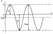
図5は、直流電源201と交流電源202とから出力される重畳バイアスの波形の一例を示す波形図である。
FIG. 5 is a waveform diagram showing an example of a superimposed bias waveform output from the
図5において、オフセット電圧Voffは、重畳バイアスの直流成分の値である。また、Peak−to−Peak電圧Vppは、重畳バイアスの交流成分のPeak−to−Peak電圧である。 In FIG. 5, the offset voltage Voff is the value of the DC component of the superimposed bias. The Peak-to-Peak voltage Vpp is a Peak-to-Peak voltage that is an alternating current component of the superimposed bias.
重畳バイアスは、オフセット電圧VoffとPeak−to−Peak電圧Vppとを重畳したものであり、その時間平均値はオフセット電圧Voffと同じ値になる。 The superposition bias is a superposition of the offset voltage Voff and the peak-to-peak voltage Vpp, and the time average value thereof is the same value as the offset voltage Voff.
図示のように、重畳バイアスは正弦波状の形状をしており、プラス側のピーク値と、マイナス側のピーク値とを具備している。 As shown in the figure, the superimposed bias has a sinusoidal shape, and has a positive peak value and a negative peak value.
図中Vtで示されているのは、それら2つのピーク値のうち、二次転写ニップ内でトナーを中間転写ベルト側から記録紙側に移動させる方(本実施形態ではマイナス側)のピーク値である。また、図中Vrで示されているのは、トナーを記録紙側から中間転写ベルト側に戻す方(本実施形態ではプラス側)のピーク値である。 Of these two peak values, Vt in the figure indicates the peak value of the one that moves the toner from the intermediate transfer belt side to the recording paper side in the secondary transfer nip (minus side in this embodiment). It is. In addition, Vr in the figure indicates a peak value on the way of returning the toner from the recording paper side to the intermediate transfer belt side (plus side in this embodiment).
直流成分を含む重畳バイアスを印加して、その時間平均値であるオフセット電圧Voffをトナーと同じ極性(本実施形態ではマイナス)にする。このことで、トナーを往復移動させながら、相対的には中間転写ベルト側から記録紙側にトナーを移動させて記録紙P上に転移させることが可能になる。 A superimposed bias including a direct current component is applied so that the time average value of the offset voltage Voff has the same polarity as that of the toner (minus in this embodiment). This makes it possible to move the toner from the intermediate transfer belt side to the recording paper side and transfer it onto the recording paper P while moving the toner back and forth.
なお、交流電圧としては、正弦波形状の波形のものを採用しているが、矩形波状の波形のものを用いても良い。 Note that a sinusoidal waveform is used as the AC voltage, but a rectangular waveform may also be used.
また、交流成分のうち、トナーを中間転写ベルト側から記録紙側に移動させる時間(本実施形態ではマイナス側)と、トナーを記録紙側から中間転写ベルト側に戻す時間(本実施形態ではプラス側)とを、異なる時間とすることも可能である。 Among the AC components, the time for moving the toner from the intermediate transfer belt side to the recording paper side (minus side in this embodiment) and the time for returning the toner from the recording paper side to the intermediate transfer belt side (plus in this embodiment) It is also possible to set different times.
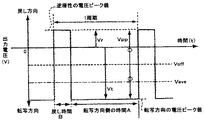
図6に示す例では、交流成分の1周期において、トナーを中間転写ベルト側から記録紙側にトナーを移動させる転写方向側の時間Aを、記録紙側から中間転写ベルト側にトナーを移動させる戻し側の時間Bよりも大きく設けたものである。 In the example shown in FIG. 6, the time A on the transfer direction side for moving the toner from the intermediate transfer belt side to the recording paper side in one cycle of the AC component, and the toner from the recording paper side to the intermediate transfer belt side are moved. It is set larger than the time B on the return side.
ただし、図6に示した波形は一例であり、転写方向側の時間Aと戻し側の時間Bとの比率も適宜設定可能である。 However, the waveform shown in FIG. 6 is an example, and the ratio between the time A on the transfer direction side and the time B on the return side can be set as appropriate.
和紙調の用紙やエンボス加工が施された用紙など、表面の凹凸の大きい記録紙Pを用いる場合には、重畳バイアスを印加する。これにより、上述のように、トナーを往復移動させながら相対的には中間転写ベルト側から記録紙側にトナーを移動させて記録紙P上に転移させることで、用紙凹部への転写性を向上させ、転写率の向上や中抜けなどの異常画像を改善させることができる。 When recording paper P having a large surface irregularity, such as Japanese paper or embossed paper, is used, a superimposed bias is applied. As a result, as described above, the toner is moved relatively from the intermediate transfer belt side to the recording paper side and transferred onto the recording paper P while reciprocating the toner, thereby improving the transferability to the paper recess. Therefore, it is possible to improve abnormal images such as an increase in transfer rate and voids.
しかしながら、転写バイアスとして重畳バイアスからなるものを印加すると、直流電圧だけからなるものを印加する場合に比べて、転写チリを発生させ易くなることが知られている。転写チリは、転写工程において、トナーを画像部の周囲に飛び散らせてしまう現象である。 However, it is known that applying a superimposed bias as the transfer bias makes it easier to generate transfer dust compared to applying a DC voltage alone. Transfer dust is a phenomenon in which toner is scattered around the image area in the transfer process.
転写バイアスの交流成分の周波数が高くなるほど、二次転写ニップにおける中間転写ベルト51と記録紙Pとの間のトナーの往復移動回数が増加するため、転写チリが発生し易くなる。周波数を最適化することで転写チリを抑えることはできるが、環境条件によっては転写チリが発生してしまう場合がある。
As the frequency of the AC component of the transfer bias increases, the number of reciprocating movements of the toner between the
一方、通常の転写紙など、凹凸の小さい記録紙P(平滑紙、コート紙など)を用いる場合には、直流成分のみによる二次転写バイアスの印加で充分な転写性が得られる。 On the other hand, when recording paper P (smooth paper, coated paper, etc.) with small unevenness such as ordinary transfer paper is used, sufficient transferability can be obtained by applying a secondary transfer bias only with a direct current component.
そこで、記録紙Pの紙種によっては、重畳バイアスを必要としない紙種もあり、その場合は、重畳バイアスを印加せずとも十分な転写性があるため、交流バイアスを印加せずに直流バイアスのみの印加とする。これにより、転写チリの発生を抑えることができる。 Therefore, depending on the paper type of the recording paper P, there is a paper type that does not require a superimposing bias. In this case, since there is sufficient transferability without applying a superimposing bias, a direct current bias is not applied without applying an alternating bias. Apply only. Thereby, generation | occurrence | production of transfer dust can be suppressed.
よって、通常の転写紙等の凹凸の小さな記録紙Pを用いた場合の直流バイアス印加と、凹凸の大きな記録紙Pを用いた場合の重畳バイアス印加とを切り替えることによって、多様な記録紙Pに対しても良好な転写性を得ることが可能となる。また、必要のあるときだけ交流電源202をONするため、長寿命化にも繋がる。
Therefore, by switching between applying a DC bias when using a recording paper P with small unevenness such as a normal transfer paper and applying a superimposed bias when using a recording paper P with large unevenness, various recording papers P can be used. In contrast, good transferability can be obtained. In addition, since the
次に、重畳バイアスによる高圧出力と、直流バイアスによる高圧出力との立ち上がり時間について説明する。 Next, the rise time of the high voltage output due to the superimposed bias and the high voltage output due to the DC bias will be described.
図7は、重畳バイアスによる高圧出力と直流バイアスによる高圧出力との立ち上がり時間の一例の説明図である。図8は、直流電源201からなる二次転写バイアス電源200の電源構成を示す図である。
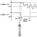
FIG. 7 is an explanatory diagram of an example of the rise time of the high voltage output by the superimposed bias and the high voltage output by the DC bias. FIG. 8 is a diagram showing a power supply configuration of the secondary transfer bias
なお、立ち上がりとは、電位差のない状態(0[kV])から、プラスマイナスを問わず電位差のある状態になることである。また、参考までに、立ち下がりとは、プラスマイナスを問わず電位差のある状態から、電位差のない状態(0[kV])になることである。 Note that the term “rise” refers to a state in which there is a potential difference regardless of plus or minus from a state without potential difference (0 [kV]). For reference, the term “falling” refers to a state where there is no potential difference (0 [kV]) from a state where there is a potential difference regardless of whether it is positive or negative.
図8に示すような二次転写バイアス電源200を用い定電流制御にて、直流バイアスのみを高圧出力させる場合、直流バイアスの立ち上がり時間は図7(b)に示すようになる。
When only the DC bias is output at high voltage by the constant current control using the secondary transfer
すなわち、二次転写バイアス電源200に直流バイアスの出力指示が行われてから、二次転写バイアス電源200のバイアス値が狙いの値(例えば−10[kV]相当)となるまでに、50[ms]要している。
That is, 50 [ms] from when the direct bias output instruction is given to the secondary transfer bias
なお、二次転写バイアス電源200に直流バイアスの出力指示は、二次転写バイアス電源200への直流バイアス出力信号の出力で行われる。
Note that a DC bias output instruction to the secondary transfer bias
一方、図4に示すような二次転写バイアス電源200を用い定電流制御にて、重畳バイアスを高圧出力させる場合、重畳バイアスの立ち上がり時間は図7(a)に示すようになる。
On the other hand, when the superimposed bias is output at a high voltage by the constant current control using the secondary transfer
すなわち、二次転写バイアス電源200に重畳バイアスの出力指示が行われてから、二次転写バイアス電源200のバイアス値(オフセット電圧Voff)が狙いの値(例えば−10[kV]相当)となるまでに、600[ms]要している。
That is, after the superimposing bias output instruction is given to the secondary transfer bias
なお、二次転写バイアス電源200に重畳バイアスの出力指示は、二次転写バイアス電源200への直流バイアス出力信号及び交流バイアス出力信号の出力で行われる。
The superimposing bias output instruction to the secondary transfer bias
このように、二次転写バイアス電源200に重畳バイアスで高圧出力させる場合、直流バイアスのみで高圧出力させる場合に比べ、バイアス値が狙いの値となるまでに時間を要してしまう。
As described above, when a high voltage is output to the secondary transfer bias
これは、交流電源202は負荷調整用のコンデンサを有しており、このコンデンサは、ある程度の容量を備えることで交流の波形を維持している。一方、重畳バイアスの直流成分は、定電流制御され、突入防止のために所定の低い電流で出力を行っており、負荷調整用のコンデンサによる重畳バイアスの直流成分のチャージに時間がかかる。この結果、電圧の立ち上がり時間に遅れが生じる。
This is because the
なお、重畳バイアスの交流成分も負荷調整用のコンデンサにチャージされるが、重畳バイアスの交流成分は、定電圧制御されており、はじめから大きな電圧を重畳しても問題が起きないため、負荷調整用のコンデンサのチャージに時間があまりかからない。 The superimposed bias AC component is also charged to the load adjustment capacitor, but the superimposed bias AC component is controlled at a constant voltage, so there is no problem even if a large voltage is superimposed from the beginning. It takes less time to charge the capacitor.
ここで、特開2008−275844号公報に記載の画像形成装置では、記録紙の画像領域が二次転写部を通過しているときに、直流電圧のみを出力する転写電源を定電圧制御して転写バイアスを印加している。そして、記録紙の画像領域が二次転写部を通過するときに印加する転写バイアスを、二次転写部に記録紙がないときに測定した電圧値から印字枚数や紙種紙厚によって補正している。 Here, in the image forming apparatus described in Japanese Patent Application Laid-Open No. 2008-275844, when the image area of the recording paper passes through the secondary transfer unit, the transfer power source that outputs only a DC voltage is controlled at a constant voltage. A transfer bias is applied. Then, the transfer bias applied when the image area of the recording paper passes through the secondary transfer portion is corrected by the number of printed sheets and the paper type paper thickness from the voltage value measured when there is no recording paper in the secondary transfer portion. Yes.
一方、本実施形態では、立ち上げ時の非画像領域で印加する転写バイアスの直流成分を定電圧制御し、記録紙の画像領域が二次転写部を通過するときに印加する転写バイアスの直流成分を定電流制御している。 On the other hand, in this embodiment, the DC component of the transfer bias applied in the non-image area at the start-up is controlled by constant voltage, and the DC component of the transfer bias applied when the image area of the recording paper passes through the secondary transfer portion. The constant current is controlled.
図1は、重畳バイアスの直流成分の制御信号と出力波形とを示す模式図である。図1(a)は、制御部300から二次転写バイアス電源200に送られる定電圧制御信号の波形を示したものである。図1(b)は、制御部300から二次転写バイアス電源200に送られる定電流制御信号の波形を示したものである。図1(c)は二次転写対向ローラ53に出力されるバイアス(電流または電圧)の出力を示したものである。
FIG. 1 is a schematic diagram showing a control signal and an output waveform of the DC component of the superimposed bias. FIG. 1A shows a waveform of a constant voltage control signal sent from the
また、図9は、重畳バイアスの直流成分を定電流制御で立ち上げた場合と定電圧制御で立ち上げた場合とでの立ち上げ時間を比較したものである。図9(a)は、重畳バイアスの直流成分を定電流制御で立ち上げた場合の立ち上げ時間を示したものである。図9(b)は、重畳バイアスの直流成分を定電圧制御で立ち上げた場合の立ち上げ時間を示したものである。 FIG. 9 compares the rise times when the DC component of the superimposed bias is raised by constant current control and when it is raised by constant voltage control. FIG. 9A shows the start-up time when the DC component of the superimposed bias is started by constant current control. FIG. 9B shows the rise time when the DC component of the superimposed bias is raised by constant voltage control.
本実施形態では、二次転写バイアス電源200に重畳バイアスで高圧出力させる場合に、重畳バイアスの直流成分を予め設定された目標電圧となるように定電圧制御で立ち上げる(図1(a)及び図1(c)参照)。これにより、図9(a)に示す重畳バイアスの直流成分を定電流制御で立ち上げた場合よりも、図9(b)に示すように立ち上がり時間を要せずに狙いのバイアス値にできる。よって、立ち上がり時間の遅れによる画像先端部の濃度の希薄化を抑制することができる。
In the present embodiment, when the secondary transfer
また、立ち上げ時の前記直流成分の電圧値は、目標電圧そのもので設定されるので、環境変動などに起因して前記直流成分の立ち上がりの勾配が変化しても、前記直流成分を狙いの目標電圧にすることができる。 In addition, since the voltage value of the DC component at the time of start-up is set by the target voltage itself, even if the rising gradient of the DC component changes due to environmental fluctuations or the like, the DC component is targeted. Can be voltage.
また、予め設定された目標電圧となるように定電圧制御で立ち上げた後、中間転写ベルト51上のトナー像が記録紙Pに転写される前に、予め設定された目標電流となるよう定電流制御に切り替える(図1(b)及び図1(c)参照)。
In addition, after starting up with constant voltage control so as to have a preset target voltage, before the toner image on the
このように、中間転写ベルト51上のトナー像を記録紙Pに転写するときには、定電流制御で転写バイアスを印加することで、中間転写ベルト51などの電気抵抗が温度湿度環境などで変動しても、転写電界を安定させて、安定した転写性を得ることができる。
As described above, when the toner image on the
なお、図1において、定電圧制御で電圧を立ち上げるとき(紙先端が転写ニップに到達する前)には、二次転写ローラ56と中間転写ベルト51とを離間させておく。そして、記録紙P上の画像(トナー像)が二次転写位置へ到達する前に、二次転写ローラ56を中間転写ベルト51に当接させて転写ニップを形成するようにしても良い。
In FIG. 1, when the voltage is raised by constant voltage control (before the leading edge of the paper reaches the transfer nip), the
また、定電圧制御で電圧を立ち上げるとき(紙先端が転写ニップに到達する前)には、画像転写時よりも弱い加圧力で二次転写ローラ56を中間転写ベルト51へ当接しておき、記録紙P上の画像(トナー像)が二次転写位置に到達する前に加圧力を高めても良い。
Further, when the voltage is raised by constant voltage control (before the leading edge of the paper reaches the transfer nip), the
また、図1では、紙先端が転写ニップに到達すると、二次転写バイアス電源200を低電圧制御から定電流制御へ切り替えているが、これに限るものではない。すなわち、紙先端が転写ニップへ到達した後であって画像先端が転写ニップへ到達するまでの間に、二次転写バイアス電源200を定電圧制御から定電流制御へ切り替えても良い。
In FIG. 1, when the leading edge of the paper reaches the transfer nip, the secondary transfer
また、電子写真に用いる記録紙Pは多種多様なものがあり、記録紙Pの材料や厚みの違いにより、良好な転写を行う最適な転写バイアスは異なり、また、画像先端部分での最適な転写バイアスも異なる。 In addition, there are various types of recording paper P used for electrophotography, and the optimum transfer bias for good transfer varies depending on the material and thickness of the recording paper P, and the optimum transfer at the leading edge of the image. The bias is also different.
そのため、立ち上がり定電圧制御の目標電圧も薄紙や厚紙などの記録紙Pの種類によって、最適な電圧にすることが好ましい。 For this reason, the target voltage for the rising constant voltage control is preferably set to an optimum voltage depending on the type of the recording paper P such as thin paper or thick paper.
例えば、記録紙Pの種類によらず一定電圧にした場合、薄紙では画像部先端バイアスが高すぎて過転写となり、また、厚紙では転写不足となり、異常画像(白ポチ、濃度薄など)が発生する可能性がある。 For example, when a constant voltage is used regardless of the type of recording paper P, the image area tip bias is too high for thin paper, resulting in overtransfer, and for thick paper, transfer is insufficient, resulting in abnormal images (white spots, low density, etc.). there's a possibility that.
そこで、本実施形態では記録紙Pの違いによる対応は、紙厚と紙種すなわち記録紙Pの厚さと表面性の違いによって、適正な目標電圧に変える。なお、表1に一例を示したが、特にこれに限定されるものではない。 Therefore, in the present embodiment, the correspondence due to the difference in the recording paper P is changed to an appropriate target voltage depending on the difference in the paper thickness and paper type, that is, the thickness of the recording paper P and the surface property. In addition, although an example was shown in Table 1, it is not specifically limited to this.

ここで、特開2012−42827号公報には、紙種や紙厚によって、直流成分と交流成分とを重畳した転写バイアスの交流成分の電圧を変更することが開示されているが、立ち上げ時における直流成分の目標電圧を変更することは開示されていない。 Here, Japanese Patent Laid-Open No. 2012-42827 discloses changing the voltage of the AC component of the transfer bias in which the DC component and the AC component are superimposed depending on the paper type and paper thickness. There is no disclosure of changing the target voltage of the direct current component in.
また、本実施形態では、出力電圧(二次転写部の抵抗値)を検知して立ち上がりの目標電圧を制御(補正)する。 In this embodiment, the output voltage (the resistance value of the secondary transfer portion) is detected to control (correct) the target voltage for rising.
転写性には、二次転写ローラ56や二次転写対向ローラ53や中間転写ベルト51などの転写部材の電気抵抗も大きく関与している。
The transfer resistance is also greatly related to the electrical resistance of transfer members such as the
すなわち、転写部材の抵抗が低すぎると、トナー層の抵抗の影響が大きくなり、画像面積によって印加される電圧が大きく変化し、画像面積が少ないときと多いときで転写効率が変わってしまう。 That is, if the resistance of the transfer member is too low, the effect of the resistance of the toner layer increases, and the applied voltage changes greatly depending on the image area, and the transfer efficiency changes when the image area is small and large.
また、転写部材の抵抗が高すぎる場合でも、印加電圧が高くなりすぎることで電流のリークを生じて画像を乱すという問題がある。さらに、電圧が電源性能の上限まで高くなってしまった場合は、電流が流れなくなって転写が十分に行われなくなり、電源が壊れる危険性があるという問題がある。 In addition, even when the resistance of the transfer member is too high, there is a problem in that the applied voltage becomes too high, causing current leakage and disturbing the image. Furthermore, when the voltage is increased to the upper limit of the power supply performance, there is a problem in that there is a risk that the current will not flow, transfer will not be performed sufficiently, and the power supply may be broken.
中間転写ベルト51や二次転写ローラ56などの転写装置を構成する部材は、転写バイアスの印加により抵抗が徐々に変化することが一般に見られる。そのため、経時で中間転写ベルト51や二次転写ローラ56などの抵抗が変化する場合には、上述したような問題が生じることがある。
It is generally seen that the resistance of members constituting the transfer device, such as the
そこで、本実施形態では、転写バイアス値(重畳バイアスの直流成分)、重畳バイアスの交流成分、立ち上がり目標電圧)を、検知した二次転写部の抵抗値によって補正する。 Therefore, in the present embodiment, the transfer bias value (the DC component of the superimposed bias), the AC component of the superimposed bias, and the rising target voltage) is corrected by the detected resistance value of the secondary transfer unit.
図4に示す直流電源201及び交流電源202は、制御部300から定電圧制御信号や定電流制御信号などのPWM信号(Pulse Wide Modulation:パルス幅変調信号)が送られるなどして制御される。また、二次転写バイアス電源200が備える直流電源201と交流電源202とのうち、直流電源201のみが電圧検知手段203を有している。
The
電圧検知手段203で検知したフィードバック電圧は、制御部300に入力され、二次転写部での抵抗検知に用いられる。
The feedback voltage detected by the
また、交流電源202に電圧検知手段(電圧を検知する回路構成)を備えないことで、スペースを節約するとともに、コストを抑制することができる。
Further, since the
本実施形態では、二次転写バイアスとして直流バイアスを印加して画像転写を行う直流転写モードにおいて、直流電源201を用い、電圧検知手段203で検知したフィードバック電圧に基づき、二次転写部での抵抗値を算出して、転写電流値を決定し制御している。なお、二次転写部での抵抗値としては、中間転写ベルト51や記録紙Pを含む抵抗値である。また、本実施形態では、定電流制御を行っている。
In the present embodiment, in a DC transfer mode in which image transfer is performed by applying a DC bias as a secondary transfer bias, the
また、本実施形態では、電圧検知手段203による検知は、所定枚数出力(転写)ごとに検知を行うようにしている。
In the present embodiment, detection by the
図10に、直流転写モードでの直流バイアス印加時の電圧検知タイミングを示す。
なお、図10では1枚目と2枚目との紙間で電圧検知を行うように示しているが、上述したように、電圧検知は所定枚数出力(転写)ごとに実施する。
FIG. 10 shows voltage detection timing when a DC bias is applied in the DC transfer mode.
Although FIG. 10 shows that voltage detection is performed between the first sheet and the second sheet, as described above, voltage detection is performed every predetermined number of outputs (transfer).
ここでは、ジョブ中に(ジョブ中の紙間において)電圧検知を実施する例で示しているが、所定枚数を出力(転写)したジョブの終了後に電圧検知を実施するようにしても良い。 Here, an example is shown in which voltage detection is performed during a job (between sheets in a job), but voltage detection may be performed after the end of a job that outputs (transfers) a predetermined number of sheets.
また、図10では、電圧検知を実施する際に、直流電源201の出力をオフするように示しているが、必ずしもオフにする必要は無く、ある程度出力を下げる(モニタ電圧を変える)ことでも検知は可能である。
FIG. 10 shows that the output of the
基本的には、紙間では中間転写ベルト51の地汚れトナーなどを二次転写ローラ側へ転移させないようにするため二次転写バイアス電源200をオフする。そのため、図10では、紙間で電圧検知を行うときにだけ直流電源201をオンにして電圧(抵抗)を測定している。
Basically, the secondary transfer
また、紙間で二次転写バイアス電源200をオフしないまでも十分に小さくすることで、中間転写ベルト51の地汚れトナーなどの二次転写ローラ側への転移は、ある程度抑えることが可能である。そのため、紙間で直流バイアスを転写時より小さくするとともに、電圧検知時には所定の直流バイアスを印加することで、電圧検知も行うことが可能である。
In addition, by making the secondary transfer
一方、二次転写バイアスとして重畳バイアスを印加し、画像転写を行う重畳転写モードでは、重畳バイアスを印加する交流電源202が電圧検知手段を備えていないので、重畳転写モード中に直流電源201を用いて出力電圧を検知してフィードバックする。これにより、二次転写部での抵抗値を算出して、交流電源202の出力を制御(補正)するようにしている。
On the other hand, in the superimposed transfer mode in which a superimposed bias is applied as the secondary transfer bias and image transfer is performed, the
図11に、重畳転写モードでの交流バイアス印加時の電圧検知タイミングを示す。
図11では、1枚目と2枚目との紙間で電圧検知を行うように示しているが、上述したように、電圧検知は所定枚数出力(転写)ごとに実施する。
FIG. 11 shows the voltage detection timing when an AC bias is applied in the superimposed transfer mode.
In FIG. 11, voltage detection is performed between the first sheet and the second sheet. However, as described above, voltage detection is performed every predetermined number of sheets output (transfer).
ここでは、ジョブ中に(ジョブ中の紙間において)電圧検知を実施する例で示しているが、所定枚数を出力(転写)したジョブの終了後に電圧検知を実施するようにしても良い。 Here, an example is shown in which voltage detection is performed during a job (between sheets in a job), but voltage detection may be performed after the end of a job that outputs (transfers) a predetermined number of sheets.
図11に示すタイミングチャートから分かるように、直流電源201を用いた出力電圧検知時には、交流電源202の出力をオフしている。
As can be seen from the timing chart shown in FIG. 11, the output of the
すなわち、重畳転写モード中に、一時的に電源を交流電源202から直流電源201に切り替えて出力電圧(二次転写部の抵抗値)を検知している。
That is, during the superimposing transfer mode, the output voltage (resistance value of the secondary transfer portion) is detected by temporarily switching the power source from the
重畳転写モード中の出力電圧検知時に、交流電源202の出力をオフすることで、交流電源202の出力に影響されずに電圧検知を行うことができる。
When the output voltage is detected in the superimposing transfer mode, the output of the
なお、本実施形態では、出力電圧(二次転写部の抵抗値)を検知して電源の出力を制御(補正)する場合、抵抗値が高ければ電源出力を小さくする方向に、抵抗値が低くなれば電源出力を大きくする方向に制御する。 In this embodiment, when the output voltage (resistance value of the secondary transfer portion) is detected and the output of the power source is controlled (corrected), if the resistance value is high, the resistance value is low in the direction of decreasing the power output. If so, the power output is controlled to increase.
所定枚数形成ごとに出力電圧(二次転写部の抵抗値)を検知して電源の出力を補正することで、経時において良好な転写性を維持することが可能となる。 By detecting the output voltage (resistance value of the secondary transfer portion) and correcting the output of the power source every time a predetermined number of sheets are formed, it is possible to maintain good transferability over time.
また、立ち上がり定電圧制御の目標電圧についても、同様に検知した出力電圧(二次転写部の抵抗値)に応じて補正する。 Further, the target voltage for the rising constant voltage control is also corrected according to the detected output voltage (the resistance value of the secondary transfer portion).
電圧検知に用いる電流を例えば25[μA]とした場合、検知電圧は表2のようになる。 When the current used for voltage detection is, for example, 25 [μA], the detection voltage is as shown in Table 2.
二次転写部の抵抗値(この場合はローラ抵抗)によって検知電圧は異なり、抵抗が高いほど電圧は高くなっているため、検知電圧によって転写部材の抵抗値が分かる。 The detection voltage varies depending on the resistance value of the secondary transfer portion (in this case, the roller resistance), and the higher the resistance, the higher the voltage. Therefore, the resistance value of the transfer member can be determined from the detection voltage.
このように転写部材の抵抗値は、検知電圧が電圧閾値よりも低いか高いかによって判断することができ、その転写部材の抵抗によって、最適な抵抗補正係数を乗じることより、最適な立ち上がり目標電圧に設定することが可能である。 In this way, the resistance value of the transfer member can be determined based on whether the detected voltage is lower or higher than the voltage threshold value, and the optimum rise target voltage is obtained by multiplying the resistance of the transfer member by the optimum resistance correction coefficient. Can be set.
さらに、温度と相対湿度との少なくとも一方を検知する不図示の温湿度センサなどを有する環境条件検知手段を設け、温度、相対湿度、及び、温度と相対湿度とから算出した絶対湿度のいずれか、もしくは2つ以上を組み合わせて、環境条件の変化を検知する。そして、変化量が規定値を超えた場合に(例えば温度が5[℃]変化したら)、電圧検知を実施するタイミングとしても良い。 Furthermore, an environmental condition detection unit having a temperature / humidity sensor (not shown) that detects at least one of temperature and relative humidity is provided, and either temperature, relative humidity, and absolute humidity calculated from the temperature and relative humidity, Or two or more are combined to detect changes in environmental conditions. Then, when the amount of change exceeds a specified value (for example, when the temperature changes by 5 [° C.]), the timing for performing voltage detection may be used.
直流バイアス印加時及び重畳バイアス印加時に実施したフィードバック電圧検知情報に、環境条件検知手段で検知した条件を加味して、二次転写部で印加する転写バイアス(直流バイアス、重畳バイアス)を制御(補正)しても良い。 Controls (corrects) the transfer bias (DC bias, superimposed bias) applied at the secondary transfer unit by adding the conditions detected by the environmental condition detection means to the feedback voltage detection information performed when applying the DC bias and applying the superimposed bias. )
なお、環境条件とは、LL(温度19[℃]湿度30[%])、ML(温度23[℃]湿度30[%])、MM(温度23[℃]湿度50[%])、MH(温度23[℃]湿度80[%])、HH(温度27[℃]湿度80[%])などである。しかしながら、温度や湿度の値及び組み合わせなどは、これに限定されるものではない。 The environmental conditions include LL (temperature 19 [° C.] humidity 30 [%]), ML (temperature 23 [° C.] humidity 30 [%]), MM (temperature 23 [° C.] humidity 50 [%]), MH. (Temperature 23 [° C.] humidity 80 [%]), HH (temperature 27 [° C.] humidity 80 [%]), and the like. However, the values and combinations of temperature and humidity are not limited to this.
これにより、環境条件に応じた良好な転写性を得ることが可能となる。なお、数1に、ローラ抵抗と環境条件とを考慮した定電圧制御の目標電圧を求める際に用いる算出式の一例を示す。また、ローラ抵抗と環境条件との相互関係に応じた目標電圧の補正係数の一例を表3に示すが、これに限定されるものではない。
This makes it possible to obtain good transferability according to the environmental conditions.
![]()
![]()
例えば、ローラ抵抗と環境条件とを考慮しない場合、表1に示すように紙厚3の普通紙における目標電圧が−2.3[kV]であるとし、これを数1の「電圧標準値」とする。そして、ローラ抵抗と環境条件を考慮して、表3に示すように検知電圧が1.0[kV]以下でローラ抵抗が7.0乗であり、環境条件がMMの場合には、目標電圧の補正係数(数1の「電圧環境補正係数×電圧抵抗補正係数」に相当)が90[%]となる。
For example, when the roller resistance and the environmental condition are not considered, as shown in Table 1, it is assumed that the target voltage for plain paper with a paper thickness of 3 is −2.3 [kV], and this is the “voltage standard value” of
そのため、数1から目標電圧=−2.3[kV]×0.9=−2.07[kV]のように、ローラ抵抗と環境条件を考慮した目標電圧を求めることができる。
Therefore, the target voltage in consideration of the roller resistance and the environmental conditions can be obtained from
また、目標電圧の補正係数として、ローラ抵抗と環境条件との相互関係に応じたものだけではなく、温度に応じた補正係数や、湿度に応じた補正係数や、温度と湿度に応じた補正係数や、ローラ抵抗に応じた補正係数を用いて、目標電圧の補正制御を行っても良い。 In addition, the target voltage correction factor is not limited to the correlation between roller resistance and environmental conditions, but also the correction factor according to temperature, the correction factor according to humidity, and the correction factor according to temperature and humidity. Alternatively, the target voltage correction control may be performed using a correction coefficient corresponding to the roller resistance.
以上のように、二次転写バイアス電源200の交流電源202がフィードバック電圧を検知する構成を有していなくとも、重畳バイアスを印加しての転写モード時に、二次転写部における抵抗値を算出して、最適な転写バイアス印加を実施することができる。
As described above, even if the
すなわち、交流電源202の省スペース及び低コストを実現した上で、適切な重畳バイアス印加により良好な転写性を得ることができる。
That is, while realizing space saving and low cost of the
なお、二次転写バイアス電源200による転写バイアス印加時の電圧を検知しつつ、転写バイアスが目標電圧となるように定電圧制御を行っても良い。
Note that constant voltage control may be performed so that the transfer bias becomes the target voltage while detecting the voltage when the transfer bias is applied by the secondary transfer
重畳バイアスは、凹凸の大きな記録紙Pにおいて良好な転写性を得ることができる。そのため、通常の転写紙等の凹凸の小さな記録紙Pを用いた場合の直流バイアス印加と、凹凸の大きな記録紙Pを用いた場合の重畳バイアス印加とを切り替えることによって、多様な用紙に対しても良好な転写性を得ることが可能となる。 The superimposing bias can provide good transferability on the recording paper P having large irregularities. Therefore, by switching between applying a DC bias when using a recording paper P with small unevenness, such as a normal transfer paper, and applying a superimposed bias when using a recording paper P with large unevenness, various papers can be used. In addition, good transferability can be obtained.
また、凹凸の小さな記録紙Pを用いる場合などに、図4に示す電源構成の二次転写バイアス電源200で交流バイアスを印加せずに直流バイアスのみの印加とするときにおいても、直流バイアス立ち上げ時には目標電圧となるように定電圧制御で立ち上げる。そして、予め設定された目標電圧となるように定電圧制御で立ち上げた後、中間転写ベルト51上のトナー像が記録紙Pに転写される前に、予め設定された目標電流となるよう定電流制御に切り替える。
Further, when the recording paper P with small unevenness is used, when the secondary transfer
交流バイアスを印加せずに直流バイアスのみを印加する際に、定電流制御で立ち上げた場合でも、上述したように交流電源202が有する負荷調整用のコンデンサの影響によって、立ち上がり時間が遅くなってしまう。
Even when only a DC bias is applied without applying an AC bias, even when the constant current control is used, the rise time is delayed due to the influence of the load adjusting capacitor of the
そのため、図4に示す電源構成の二次転写バイアス電源200で交流バイアスを印加せずに直流バイアスのみを印加する際に、定電圧制御で立ち上げることで、定電流制御で立ち上げた場合よりも、立ち上がり時間を要せずに狙いのバイアス値にできる。よって、立ち上がり時間の遅れによる画像先端部の濃度の希薄化を抑制することができる。
Therefore, when only the DC bias is applied without applying the AC bias in the secondary transfer bias
さらに、直流バイアス印加時及び重畳バイアス印加時の双方において、電圧検知を実施し二次転写部での抵抗値を算出することができるため、環境条件等により変化する抵抗値に応じた適切な転写電流値でのバイアス制御が可能となる。 Furthermore, voltage detection can be performed both when applying a DC bias and when applying a superimposed bias, and the resistance value at the secondary transfer unit can be calculated. Bias control with current value is possible.
なお、上記のように本実施形態では、直流バイアス印加時及び重畳バイアス印加時の電圧検知を実施するタイミングとして、所定枚数出力ごと(ジョブ中)としたが、これに限定されるものではない。例えば、所定枚数を印刷したジョブ後や、装置立ち上げ時、画像形成条件を調整する画像調整制御前のタイミングなど、適宜なタイミングで行うようにしても良い。 As described above, in the present embodiment, the timing for detecting the voltage when the DC bias is applied and when the superimposed bias is applied is set for every predetermined number of outputs (during the job), but is not limited thereto. For example, it may be performed at an appropriate timing such as after a job for printing a predetermined number of times, at the time of starting up the apparatus, or before the image adjustment control for adjusting the image forming conditions.
ここで、特開平7−168403号公報に記載の画像形成装置では、製品の工場出荷時、あるいは市場での保守、点検時に行われる調整モードにて転写電圧を検出測定しメモリに記憶しておく。そして、画像形成時に、直流電圧のみを出力する転写電源を定電圧制御して、メモリに記憶された転写電圧まで立ち上げる。そのため、紙種や紙厚、環境条件などが変わっても、即時に適応することができない。 Here, in the image forming apparatus described in Japanese Patent Application Laid-Open No. 7-168403, the transfer voltage is detected and measured and stored in a memory in an adjustment mode performed at the time of product shipment from the factory or maintenance and inspection in the market. . Then, at the time of image formation, a transfer power source that outputs only a DC voltage is controlled to a constant voltage, and the transfer voltage stored in the memory is raised. Therefore, even if the paper type, paper thickness, environmental conditions, etc. change, it cannot be applied immediately.
これに対して、本実施形態の画像形成装置においては、前記調整モードなどを行うことなく、紙種や紙厚、環境条件などの印刷条件に応じて予め設定された最適な目標電圧で立ち上げることが可能である。そのため、紙種や紙厚、環境条件などが変わっても、自動で即時に適応することができる。 On the other hand, in the image forming apparatus according to the present embodiment, the image forming apparatus is started up with an optimum target voltage set in advance according to printing conditions such as paper type, paper thickness, and environmental conditions without performing the adjustment mode. It is possible. Therefore, even if the paper type, paper thickness, environmental conditions, etc. change, it can be automatically and immediately adapted.
また、印刷条件によって前記目標電圧値を変更するだけではなく、印刷条件によって立ち上げ時の転写バイアスの直流成分を定電圧制御する時間を変更してもよい。 In addition to changing the target voltage value depending on the printing conditions, the time for constant voltage control of the DC component of the transfer bias at the start-up may be changed depending on the printing conditions.
上述したように、電子写真に用いる記録紙Pは多種多様なものがあり、記録紙Pの材料や厚みの違いにより、良好な転写を行う最適な転写バイアスは異なり、また、画像先端部分での最適な転写バイアスも異なる。 As described above, there are a wide variety of recording papers P used for electrophotography, and the optimum transfer bias for good transfer varies depending on the material and thickness of the recording paper P. The optimum transfer bias is also different.
そのため、上述したように立ち上がり定電流制御の目標電圧を印刷条件によって最適な目標電圧に設定することで、良好な転写を行うことは可能であるが、目標電圧が異なると立ち上げ時に目標電圧まで到達するのにかかる時間も異なることになる。 For this reason, as described above, it is possible to perform good transfer by setting the target voltage of the rising constant current control to an optimum target voltage according to the printing conditions. The time it takes to reach will also be different.
図12(a)は、目標電圧が高い場合の立ち上げ時間を示したものである。図12(b)は、目標電圧が低い場合の立ち上がり時間を示したものである。 FIG. 12A shows the start-up time when the target voltage is high. FIG. 12B shows the rise time when the target voltage is low.
例えば、印刷条件として低温低湿環境の場合には、転写部材や記録紙Pの抵抗上昇によって最適な転写バイアスが高くなる。そのため、立ち上げ時の目標電圧を高くするが、図12(a)に示すように目標電圧が高いと目標電圧に到達する時間が長くなる。 For example, when the printing condition is a low temperature and low humidity environment, the optimum transfer bias is increased due to an increase in resistance of the transfer member or the recording paper P. Therefore, although the target voltage at the time of start-up is increased, as shown in FIG. 12A, when the target voltage is high, the time for reaching the target voltage becomes long.
逆に、印刷条件として高温高湿環境の場合には、最適な転写バイアスが低くなる。そのため、立ち上げ時の目標電圧を低くするが、図12(b)に示すように目標電圧が低いと目標電圧に到達する時間が短くなる。 Conversely, when the printing conditions are a high temperature and high humidity environment, the optimum transfer bias is lowered. Therefore, although the target voltage at the time of start-up is lowered, as shown in FIG. 12B, when the target voltage is low, the time to reach the target voltage is shortened.
そこで、立ち上げ時に、印刷条件によって異なる目標電圧まで到達するのに必要な時間を確保できるように、印刷条件によって立ち上げ時の転写バイアスの直流成分を定電圧制御する時間を変更する。 Therefore, the time for constant voltage control of the DC component of the transfer bias at the start-up is changed according to the printing conditions so that the time required to reach a different target voltage depending on the printing conditions can be secured at the start-up.
具体的な印刷条件としては、紙種や紙厚であったり、温度や湿度などの環境条件であったり、二次転写ローラ56や二次転写対向ローラ53や中間転写ベルト51などの転写部材の電気抵抗の変化などである。
Specific printing conditions include paper type and thickness, environmental conditions such as temperature and humidity, and transfer members such as the
転写部材の電気抵抗変化については、環境条件や経時使用による電気抵抗の変化を、上述した方法で検知して、その検知結果に基づいて、立ち上げ時の定電圧制御を行う時間を変更する。 Regarding the change in the electric resistance of the transfer member, the change in the electric resistance due to the environmental conditions and the use over time is detected by the method described above, and the time for performing the constant voltage control at the start-up is changed based on the detection result.
また、環境条件では、上述した転写部材の電気抵抗の変化に加えて、立ち上がりの勾配も変わってくる。これは、環境条件によって転写部材の静電容量が異なるため、立ち上がりの勾配が変化する。例えば、高温高湿環境では、静電容量が増加するため立ち上がりの勾配が小さくなる。 In addition, under the environmental conditions, in addition to the change in the electrical resistance of the transfer member described above, the rising gradient also changes. This is because the rising slope changes because the electrostatic capacity of the transfer member varies depending on the environmental conditions. For example, in a high-temperature and high-humidity environment, since the capacitance increases, the rising gradient becomes small.
そして、これらの印刷条件に応じて、立ち上げ時の転写バイアスの直流成分を定電圧制御する時間を変更することで、目標電圧まで到達するのに必要な時間を確保することができ、最適な転写バイアスで良好な転写を行うことができる。よって、例えば、凹凸紙の濃度ムラの低減や画像先端部の画像濃度の希薄化など抑制することができる。 By changing the time for constant voltage control of the DC component of the transfer bias at the start-up according to these printing conditions, the time required to reach the target voltage can be secured, and the optimum Good transfer can be performed with a transfer bias. Therefore, for example, it is possible to suppress the density unevenness of the uneven paper and the dilution of the image density at the leading edge of the image.
一方、図12に示すように、紙間おける立ち上がりに必要な時間以外は、中間転写ベルト51上に付着したトナーが二次転写ローラ56の表面に転移しないように、転写時とは逆極性のバイアスである逆バイアスを二次転写ローラ56に印加したり、二次転写バイアス電源200をオフしたりするのが望ましい。これにより、二次転写ローラ56の表面に付着したトナーが二次転写部で記録紙Pの裏面に付着し、記録紙Pに裏面汚れが生じるのを抑制することができる。
On the other hand, as shown in FIG. 12, the toner having a polarity opposite to that at the time of transfer is applied so that the toner adhering to the
特に、紙間で二次転写ローラ56に逆バイアスを印加することで、二次転写ローラ56の表面にトナーが付着していたとしても、二次転写ローラ56の表面から中間転写ベルト51上にトナーを転移させることができる。そして、中間転写ベルト51上に転移され付着したトナーを、ベルトクリーング装置によって中間転写ベルト51上から除去する。これにより、紙間での二次転写ローラ56などのクリーニング性を確保することができる。
In particular, by applying a reverse bias to the
よって、以上のような制御を紙間で行うことにより、紙間での二次転写ローラ56などのクリーニング性を確保しつつ、凹凸紙の濃度ムラ低減や画像先端部濃度の希薄化を抑制することができる。
Therefore, by performing the above-described control between papers, it is possible to suppress unevenness in uneven paper density and dilute density at the leading edge of the image while ensuring cleanability of the
〔変形例1〕
次に、立ち上がり定電圧制御の目標電圧の制御する一変形例(以下、本変形例を「変形例1」という。)について説明する。
本実施形態のプリンタは、上述したように、イエロー(Y)、マゼンタ(M)、シアン(C)、ブラック(K)の各色トナー画像を重ね合わせたフルカラートナー像を形成するフルカラー印刷モードと、ブラック(K)のトナー画像のみからなるモノクロトナー像を形成するモノクロ印刷モードという、画像形成に用いるトナーの種類あるいはトナーの量が異なる2つの画像形成動作モードを備えている。フルカラー印刷モードは、モノクロ印刷モードと比べて、二次転写ニップで転写すべきトナーの量が多いことから、最適な二次転写バイアスは、モノクロ印刷モードよりも高く設定される。このように印刷モードの違いによって最適な転写バイアスが異なることから、印刷モードの違いによって立ち上がり定電圧制御の目標電圧を変えることが好ましい。
[Modification 1]
Next, a modified example (hereinafter, this modified example is referred to as “modified example 1”) for controlling the target voltage of the rising constant voltage control will be described.
As described above, the printer according to this embodiment includes a full-color printing mode for forming a full-color toner image in which each color toner image of yellow (Y), magenta (M), cyan (C), and black (K) is superimposed, There are two image forming operation modes different in the type of toner or the amount of toner used for image formation, namely a monochrome printing mode for forming a monochrome toner image consisting of only a black (K) toner image. In the full-color printing mode, the amount of toner to be transferred at the secondary transfer nip is larger than that in the monochrome printing mode. Therefore, the optimum secondary transfer bias is set higher than that in the monochrome printing mode. As described above, since the optimum transfer bias differs depending on the printing mode, it is preferable to change the target voltage for the rising constant voltage control depending on the printing mode.
すなわち、本変形例1では、モノクロ印刷モードで印刷する場合には、立ち上がり定電圧制御の目標電圧を、当該モノクロ印刷モードに対応して設定されている二次転写バイアスに応じた目標電圧に設定する。具体的には、モノクロ印刷モードに対応した二次転写バイアスの大きさがフルカラー印刷モードよりも小さいことから、モノクロ印刷モード時の立ち上がり定電圧制御の目標電圧は、フルカラー印刷モード時よりも小さく設定する。逆に、フルカラー印刷モードで印刷する場合には、立ち上がり定電圧制御の目標電圧を、モノクロ印刷モード時よりも大きく設定する。 That is, in the first modification, when printing in the monochrome printing mode, the target voltage of the rising constant voltage control is set to the target voltage corresponding to the secondary transfer bias set corresponding to the monochrome printing mode. To do. Specifically, since the size of the secondary transfer bias corresponding to the monochrome printing mode is smaller than that in the full color printing mode, the target voltage for the rising constant voltage control in the monochrome printing mode is set smaller than in the full color printing mode. To do. Conversely, when printing in the full-color printing mode, the target voltage for the rising constant voltage control is set larger than that in the monochrome printing mode.
なお、本変形例1では、画像形成に用いるトナーの種類又はトナーの量が異なる画像形成動作モードが、モノクロ印刷モードとフルカラー印刷モードの2つであるが、これに限られない。 In the first modification, there are two image forming operation modes in which the type or amount of toner used for image formation is different, that is, the monochrome printing mode and the full color printing mode, but are not limited thereto.
例えば、イエロー(Y)、マゼンタ(M)、シアン(C)、ブラック(K)以外の特殊トナーを用いて画像形成を行う画像形成動作モードを含んでもよい。この特殊トナーとは、例えば、高光沢画像を形成することを目的として用いられる透明トナー、蛍光画像を形成することを目的として用いられる蛍光トナー、色再現領域を広げる目的で用いられるレッド、グリーン等の有色トナー(いわゆるスポットカラートナー)などが挙げられる。 For example, an image forming operation mode in which image formation is performed using special toners other than yellow (Y), magenta (M), cyan (C), and black (K) may be included. This special toner is, for example, a transparent toner used for the purpose of forming a high gloss image, a fluorescent toner used for the purpose of forming a fluorescent image, red, green used for the purpose of expanding the color reproduction region, etc. Color toner (so-called spot color toner).
また、例えば、生産性を優先する生産性優先モードや画質を優先する画質優先モードなどの画像形成動作モードも含んでもよい。 Further, for example, an image forming operation mode such as a productivity priority mode that prioritizes productivity and an image quality priority mode that prioritizes image quality may be included.
画像形成に用いるトナーの種類やトナーの量が異なれば、最適な二次転写バイアスの大きさが変わってくる。その違いに応じて立ち上がり定電圧制御の目標電圧も変更することで、画像先端部の画像を良好にすることが可能となる。 If the type of toner and the amount of toner used for image formation are different, the optimum size of the secondary transfer bias changes. By changing the target voltage of the rising constant voltage control according to the difference, it is possible to improve the image at the leading edge of the image.
〔変形例2〕
次に、立ち上がり定電圧制御の目標電圧の制御する他の変形例(以下、本変形例を「変形例2」という。)について説明する。
本変形例2に係るプリンタは、両面印刷機能を備えたものである。すなわち、記録媒体の第1面にトナー画像を二次転写し、定着装置90にて定着処理をした後に、その記録媒体を二次転写ニップへ再び搬送し、その記録媒体の第2面に別のトナー画像を二次転写するものである。このように記録媒体の両面に画像形成を行う場合、第2面への二次転写時における記録媒体は、第1面上のトナー画像を定着装置90で定着処理した際に記録媒体中の水分が減少しているため、電気抵抗値が高くなった状態となっている。そのため、電気抵抗値が低い状態の記録媒体に対する第1面への二次転写時と、電気抵抗値が高い状態の記録媒体に対する第2面への二次転写時とでは、最適な二次転写バイアスの大きさが異なってくる。
[Modification 2]
Next, another modified example (hereinafter, this modified example is referred to as “modified example 2”) for controlling the target voltage of the rising constant voltage control will be described.
The printer according to the second modification has a double-sided printing function. That is, after the toner image is secondarily transferred to the first surface of the recording medium and fixed by the fixing
したがって、本変形例2では、第1面への二次転写時に設定される二次転写バイアスに応じて第1面への二次転写時の立ち上がり定電圧制御の目標電圧を設定するとともに、第2面への二次転写時に設定される二次転写バイアスに応じて第2面への二次転写時の立ち上がり定電圧制御の目標電圧を設定する。このように、記録媒体の第1面にトナー像を転写するときの定電圧制御の目標電圧と、前記第1面にトナー像を転写した後に前記記録媒体の第2面に別のトナー像を転写するときの定電圧制御の目標電圧とを異ならせることで、画像先端部の画像を良好にすることが可能となる。 Therefore, in the second modification, the target voltage of the rising constant voltage control at the time of secondary transfer to the first surface is set according to the secondary transfer bias set at the time of secondary transfer to the first surface, and the first A target voltage for rising constant voltage control at the time of secondary transfer to the second surface is set according to the secondary transfer bias set at the time of secondary transfer to the second surface. Thus, the target voltage for constant voltage control when transferring the toner image to the first surface of the recording medium, and another toner image on the second surface of the recording medium after the toner image is transferred to the first surface. By differentiating the target voltage of the constant voltage control at the time of transfer, it becomes possible to improve the image at the front end of the image.
〔変形例3〕
次に、立ち上がり定電圧制御の目標電圧の制御する更に0他の変形例(以下、本変形例を「変形例3」という。)について説明する。
本変形例3に係るプリンタは、フルカラー印刷モードについてプロセス線速が異なる2つのモードが存在する。具体的には、プロセス線速を遅くしたフルカラー印刷モードは、例えば、良好な定着性を得るために定着装置90を通過する記録媒体の速度が遅くなるようにしたモードである。プロセス線速すなわち記録媒体の搬送速度が変わると、最適な二次転写バイアスの大きさも変わってくる。したがって、本変形例3では、記録媒体の搬送速度の違いに応じて定電圧制御の目標電圧を変更している。これにより、画像先端部の画像を良好にすることが可能となる。
[Modification 3]
Next, another modification example (hereinafter, this modification example is referred to as "modification example 3") for controlling the target voltage of the rising constant voltage control will be described.
The printer according to the third modification has two modes with different process line speeds in the full color printing mode. Specifically, the full-color printing mode in which the process linear speed is slowed is a mode in which, for example, the speed of the recording medium passing through the fixing
[実施形態2]
以下、本発明を上記実施形態1と同様に、画像形成装置であるプリンタに適用した他の実施形態(以下、本実施形態を「実施形態2」という。)について説明する。本実施形態のプリンタは、中間転写ベルト51と二次転写ローラ56とを接離させる接離機構を有する点を除き、その装置構成や実施可能な制御など上記実施形態1のものと同様である。そのため、以下の説明では、上記実施形態1のプリンタとは異なる点について説明する。
[Embodiment 2]
Hereinafter, as in the first embodiment, another embodiment in which the present invention is applied to a printer that is an image forming apparatus (hereinafter, this embodiment is referred to as “second embodiment”) will be described. The printer of the present embodiment is the same as that of the first embodiment except for the fact that it has a contact / separation mechanism for contacting / separating the
本実施形態のプリンタにおいては、用紙が二次転写ニップに突入するときや抜けるときに、予め二次転写ローラ56と中間転写ベルト51とを離間させておき、用紙Pが二次転写ニップに突入するときや抜けるときの衝撃によるショックジターを低減させている。
In the printer of this embodiment, when the paper enters the secondary transfer nip or when the paper leaves, the
ショックジターとは、用紙Pが二次転写ニップに突入するときや抜けるときの衝撃によって、中間転写ベルト51にトルク負荷が発生し、感光体ドラム11と中間転写ベルト51との間に速度差が発生して、印刷画像に横筋状の濃度ムラを生じさせ印刷不良を引き起こしてしまうことである。
The shock jitter is that a torque load is generated on the
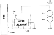
図13は、中間転写ベルト51と二次転写ローラ56とを接離させる接離機構60の模式図である。二次転写ローラ56と二次転写対向ローラ53とは、中間転写ベルト51を挟んで二次転写ローラ56が下側で二次転写対向ローラ53が上側に位置するように対向配置されている。二次転写ローラ56には、付勢手段であるバネ67によって二次転写対向ローラ53に向かうような付勢力が加わっている。
FIG. 13 is a schematic diagram of a contact /
中間転写ベルト51と二次転写ローラ56とは、ステッピングモータ63や偏心カム61などで構成された接離機構60によって一定範囲内で自由に接離させることができる。二次転写対向ローラ53の軸方向両端部には、二次転写対向ローラ53と同軸上に偏心カム61が設置されている。
The
二次転写ローラ56の軸方向両端部には、二次転写ローラ56の回転を妨げないように玉軸受62が取り付けられており、この玉軸受62に偏心カム61を突き当てるような構成となっている。偏心カム61が取り付けられているカム軸61aがステッピングモータ63からの回転駆動力により回転すると、偏心カム61も同じタイミング且つ同じ角度で回転するよう、偏心カム61とカム軸61aとがDカットの溝などで嵌め合わされて取り付けられている。
偏心カム61の形状として、偏心カム61の回転中心と外形部とを結んだ距離が最も短い部分は、二次転写対向ローラ53の直径よりも短くなっている。また、偏心カム61の回転中心と外形部とを結んだ距離が最も長い部分は、二次転写対向ローラ53の直径よりも長くなっている。
As a shape of the
カム軸61aは、ステッピングモータ63により自由に回転を制御でき、ギヤ64,65とタイミングベルト66を介することによって、ステッピングモータ63の回転駆動力がカム軸61aに伝達される。ステッピングモータ63は、ステップ角1.8[°]で回転の制御が可能であり、用紙Pが二次転写ニップに突入(進入)する前にステッピングモータ63からの回転駆動力によって偏心カム61を回転させる。
The rotation of the
ここで、「偏心カム61の回転中心から偏心カム61の玉軸受62との接触部を結んだ距離+玉軸受62の半径」を距離L1とする。また、「二次転写対向ローラ53の半径+中間転写ベルト51の厚さ+二次転写ローラ56の半径」を距離L2とする。
Here, “distance connecting the contact portion of the
偏心カム61は玉軸受62に突き当てられており、偏心カム61を回転させることによって、距離L1>距離L2の関係を満たすと、二次転写ローラ56はバネ67からの付勢に抗して中間転写ベルト51から離間する方向に押し下げられる。
The
そして、用紙先端が中間転写ベルト51と二次転写ローラ56との間を通過し始めたら、再びステッピングモータ63によって偏心カム61の回転を開始する。そして、距離L1<距離L2の関係を満たすと、中間転写ベルト51と二次転写ローラ56とが接触し、用紙Pに対して所定の転写圧が付加される。
When the leading edge of the sheet begins to pass between the
このような構成により、二次転写ニップへの用紙突入時には中間転写ベルト51と二次転写ローラ56とを離間させ、用紙突入時の衝撃や、中間転写ベルト51のプロセス線速変動(速度変動)を抑制することができる。
With such a configuration, when the paper enters the secondary transfer nip, the
また、用紙Pが二次転写ニップから抜けるときも同様に、ステッピングモータ63によって偏心カム61を回転させ、用紙Pの後端が二次転写ニップを通過する前に二次転写ローラ56と中間転写ベルト51とを離間させる。これにより、用紙Pが二次転写ニップから抜けるときの衝撃を減少させることができる。
Similarly, when the sheet P comes out of the secondary transfer nip, the
なお、接離機構60のうち、前述したような偏心カム61により玉軸受62を介して二次転写ローラ56の押し下げを行う構成が、二次転写ローラ押し下げ機構として機能する。もちろん、二次転写ローラ押し下げ機構を構成する各要素は、図13に示したものには限定されず、種々公知の手段を採用できる。
In the contact /
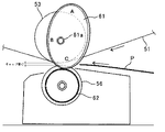
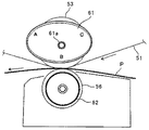
図14、図15、図16を用いて、二次転写ローラ56と二次転写対向ローラ53との接離動作について説明する。図14は、二次転写ローラ56と二次転写対向ローラ53とをギャップ量Aで離間させた状態を示す図である。図15は、二次転写ローラ56と二次転写対向ローラ53とをギャップ量Cで離間させた状態を示す図である。図16は、二次転写ローラ56と二次転写対向ローラ53とが当接した状態を示す図である。
The contact / separation operation between the
また、図14及び図15は、用紙Pが二次転写ニップに突入する前の状態を示しており、図16は、中間転写ベルト51から用紙Pにトナー像を転写しているときの状態を示している。
14 and 15 show a state before the paper P enters the secondary transfer nip, and FIG. 16 shows a state when the toner image is transferred from the
偏心カム61にはカム位置A、カム位置B、カム位置Cと3箇所の停止場所が存在し、図14に示すように、偏心カム61の位置がカム位置Aの場所で停止している場合、二次転写ローラ56と二次転写対向ローラ53とをギャップ量Aだけ離すような構成となっている。
The
また、図15に示すように、偏心カム61の位置がカム位置Cの場所で停止している場合は、二次転写ローラ56と二次転写対向ローラ53とをギャップ量Cだけ離すような構成となっている。
Further, as shown in FIG. 15, when the position of the
図16に示すように、偏心カム61の位置がカム位置Bで停止している場合は、(偏心カムの回転中心からB地点での偏心カム61外周までの偏心カム半径+玉軸受の半径)<(二次転写対向ローラ53の半径+二次転写ローラ56の半径)となっている。そのため、二次転写ローラ56と二次転写対向ローラ53とは接触状態となっている。そして、上述したように中間転写ベルト51から用紙Pにトナー像を転写する際に必要な転写圧がバネ37によって付与される。
As shown in FIG. 16, when the position of the
偏心カム61は、制御部300でステッピングモータ63を制御して伝達される回転駆動力によりカム軸61aを中心に回転することで、カム位置C−カム位置B−カム位置A−カム位置Cへと連続的にカム位置を変化させることができる。
The
図17を用いて、用紙Pが二次転写ニップに突入するときの中間転写ベルト51と二次転写ローラ56との間のギャップ量について説明する。
The gap amount between the
図14及び図15を用いて説明したように、用紙Pが二次転写ニップに突入するときには、接離機構60によって中間転写ベルト51と二次転写ローラ56とを離間させ両者の間にギャップ(隙間)が確保されている。また、このときには、中間転写ベルト51と二次転写ローラ56とが離間しているため転写圧は生じていない。
As described with reference to FIGS. 14 and 15, when the sheet P enters the secondary transfer nip, the contact /
なお、用紙Pが二次転写ニップに突入するときの中間転写ベルト51と二次転写ローラ56との間のギャップ量をY1とし、このギャップ量Y1の大きさが上述したギャップ量Aとギャップ量Cとの2水準に設定されている。ギャップ量Y1は、用紙Pが二次転写ニップに突入した際の衝撃を低減するために確保されており、用紙Pの厚さ以上の大きさを確保するのが望ましく、用紙Pの厚さに応じてギャップ量Aとギャップ量Cとが適宜設定される。
The gap amount between the
また、このギャップ量Y1を用紙Pの厚さ以上にいくら大きくしても、用紙Pが二次転写ニップに突入する際の衝撃は変化しないが、ギャップ量が大きければ大きいほど、中間転写ベルト51に対する二次転写ローラ56の接離に必要な動作が大きくなってしまう。そのため、ギャップ量Y1は用紙Pの厚さと同等よりもわずかに大きい程度確保するのが望ましい。
Even if the gap amount Y1 is increased beyond the thickness of the paper P, the impact when the paper P enters the secondary transfer nip does not change. However, the larger the gap amount, the larger the
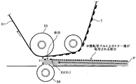
次に、図18を用いて、用紙先端が二次転写ニップを通過し、中間転写ベルト51上のトナー像Tを用紙Pに転写するときの中間転写ベルト51と二次転写ローラ56との間のギャップ量について説明する。
Next, with reference to FIG. 18, between the
中間転写ベルト51上のトナー像Tを用紙Pに転写するときの中間転写ベルト51と二次転写ローラ56と間のギャップ量をY2とする。このギャップ量Y2は、中間転写ベルト51上のトナー像Tを用紙Pに転写するのに十分な転写圧が確保されるだけのギャップ量である。なお、用紙Pの先端が二次転写ニップへ突入した後、接離機構60によって二次転写ローラ56を中間転写ベルト51に向けて移動させる接触動作を行うため、中間転写ベルト51と二次転写ローラ56との間のギャップ量Y2はギャップ量Y1以下となる。
A gap amount between the
良好な印刷結果を得るためには、用紙Pが二次転写ニップへの用紙突入時である図17の状態から、用紙先端部に形成された余白が二次転写ニップを通過するまでの間に、図18の状態へと遷移させなければならない。なお、「余白」あるいは後述する「余白部分」とは、用紙Pの印刷面にあって、画像が形成されない部分または画像を形成させない部分を言う。 In order to obtain a good printing result, the paper P is in the state of FIG. 17 when the paper enters the secondary transfer nip and the margin formed at the front end of the paper passes through the secondary transfer nip. , Transition to the state of FIG. The “margin” or “margin portion” described later refers to a portion on the printing surface of the paper P where no image is formed or where no image is formed.
そして、図17の状態から図18の状態へと遷移するのが遅れると、中間転写ベルト51上のトナー像を用紙P上へ転写する際に転写圧不足となり転写不良が発生し、色抜けが発生してしまう。
If the transition from the state shown in FIG. 17 to the state shown in FIG. 18 is delayed, the transfer pressure becomes insufficient when the toner image on the
一方、二次転写ニップへの用紙突入時に、中間転写ベルト51と二次転写ローラ56との間にギャップ量Y1が確保されていないと、二次転写ニップへの用紙突入時の衝撃が大きくなる。そのため、二次転写ニップへの用紙突入時の衝撃によるショックジターが悪化してしまう。
On the other hand, if the gap Y1 is not secured between the
用紙先端部に形成された余白の用紙先端からの余白量をX、プロセス線速をpとすると、余白部分が二次転写ニップを通過する時間tは、「t=X/p」となる。また、用紙Pが二次転写ニップに突入するときに必要なギャップ量はギャップ量Y1であり、余白部分が二次転写ニップを通過し、中間転写ベルト51上のトナー像を用紙Pに転写するときに必要なギャップ量がギャップ量Y2である。
Assuming that the margin amount of the margin formed at the leading end of the sheet is X and the process linear velocity is p, the time t for which the margin portion passes through the secondary transfer nip is “t = X / p”. Further, the gap amount required when the paper P enters the secondary transfer nip is the gap amount Y1, and the blank portion passes through the secondary transfer nip, and the toner image on the
そのため、良好な転写結果を得るには、接離機構60によって「V=(Y2−Y1)/(X/p)」以上の速度で、中間転写ベルト51に接触する方向(近づく方向)に二次転写ローラ56を移動させる必要がある。この接触動作の速度Vは、運動エネルギーとなり、中間転写ベルト51と二次転写ローラ56とが接触した際の衝撃となりショックジターの原因となる。そのため、可能な限り速度Vを遅くすることで中間転写ベルト51と二次転写ローラ56とが接触した際の衝撃によるショックジターを低減させることができる。
For this reason, in order to obtain a good transfer result, the contact /
図19は、用紙Pの先端に形成された余白の余白量の違いによって、二次転写ローラ56と中間転写ベルト51とのギャップ量のプロファイルの変化の様子を示したグラフである。
FIG. 19 is a graph showing how the profile of the gap amount between the
図19の縦軸は、二次転写ローラ56と中間転写ベルト51とのギャップ量を示している。そして、図中「Y1」は前述したように用紙Pが二次転写ニップに突入するときに必要なギャップ量であり、図中「Y2」は前述したように中間転写ベルト51上のトナー像を用紙Pに転写するときに必要なギャップ量である。
The vertical axis in FIG. 19 indicates the gap amount between the
図19の横軸は用紙先端からの位置を示しており、図中「X0」、「X1」はそれぞれ余白量をあらわしており、余白量X1の余白のほうが余白量X0の余白よりも余白が広いことをあらわしている。 The horizontal axis in FIG. 19 indicates the position from the leading edge of the paper. In the figure, “X 0 ” and “X 1 ” represent the margin amounts, respectively, and the margin with the margin amount X 1 is the margin with the margin amount X 0 . It shows that the margin is wider than that.
また、図19のグラフの傾きは、中間転写ベルト51に対する二次転写ローラ56の接触動作速度を表しており、グラフの傾きが急であるほど、前記接触動作速度が速いことを示している。
Further, the slope of the graph of FIG. 19 represents the contact operation speed of the
図19からわかるように、余白が広い(余白量が多い)ほど、ギャップ量Y1からギャップ量Y2にギャップ量を変更する際のグラフの傾きがなだらかとなり、ギャップ量Y1からギャップ量Y2にするのに最低必要な前記接触動作速度が遅くなる。そのため、余白が広い(余白量が多い)ほど、制御部300によりステッピングモータ63を制御して、前記接触動作速度を遅くすることで、中間転写ベルト51と二次転写ローラ55との接触時の衝撃を低減させることができる。
As can be seen from FIG. 19, the wider the margin (the larger the amount of margin), the gentler the slope of the graph when changing the gap amount from the gap amount Y1 to the gap amount Y2, and the gap amount Y1 is changed to the gap amount Y2. The minimum required contact operation speed is reduced. Therefore, as the margin is wider (the amount of margin is larger), the
逆に、余白が狭い(余白量が少ない)ほど、ギャップ量Y1からギャップ量Y2にギャップ量を変更する際のグラフの傾きが急になり、ギャップ量Y1からギャップ量Y2にするのに最低必要な前記接触動作速度が速くなる。前記接触動作速度が速くなるほど、中間転写ベルト51と二次転写ローラ55との接触時の衝撃が大きくなるため、その衝撃によるショックジターが発生する。
Conversely, the narrower the margin (the smaller the amount of margin), the steeper the graph when changing the gap amount from the gap amount Y1 to the gap amount Y2, and the minimum required to change the gap amount Y1 to the gap amount Y2. The contact operation speed is increased. As the contact operation speed increases, the impact at the time of contact between the
なお、余白量がX0のときに、中間転写ベルト51と二次転写ローラ55との接触時の衝撃によるショックジターが顕像化しない前記接離動作速度が得られるような最小先端余白となる。そのため、余白量がX0よりも狭い余白の場合には、前記接離動作速度が速すぎて、中間転写ベルト51と二次転写ローラ55との接触時の衝撃によるショックジターを低減させることが難しくなる。
Note that when the margin amount is X 0, the minimum edge margin as the contact and separation operation speed shock jitter due to the impact at the time of contact with the
そのため、余白量がX0よりも狭い余白の場合に、中間転写ベルト51と二次転写ローラ55との接触時の衝撃によるショックジターが顕在化しないような、ギャップ量Y2よりも多いギャップ量とすることが考えられる。しかしながらこの場合、中間転写ベルト51上のトナー像を用紙P上へ転写する際に転写圧不足となって転写不良が発生し、色抜けが発生してしまう。
Therefore, when the margin amount is narrower margin than X 0, the shock jitter due to the impact at the time of contact with the
そこで、本実施形態では、余白量がX0よりも狭い余白の場合に、余白量がX0以上の余白の場合よりも、転写バイアスの立ち上がり目標電圧を大きくすることで、転写時の転写電界を強めて、転写圧不足による転写不良が生じないように転写性能を補う。 Therefore, in this embodiment, when the margin amount is narrower margin than X 0, than if the margin amount is X 0 or margins, by increasing the rising target voltage of the transfer bias, the transfer electric field during the transfer The transfer performance is compensated so as not to cause transfer failure due to insufficient transfer pressure.
本実施形態では、X0=2.0[mm]としている。そして、余白量が2.0[mm]よりも狭い余白の場合に、余白量が2.0[mm]以上の余白の場合よりも立ち上がり目標電圧を大きくすることで、先端濃度ムラや転写圧不足を抑制し、且つ、ショックジターも低減させることが可能となる。 In this embodiment, X 0 = 2.0 [mm]. When the margin amount is narrower than 2.0 [mm], the rising target voltage is made larger than that when the margin amount is 2.0 [mm] or more so that the tip density unevenness and the transfer pressure are increased. Insufficiency can be suppressed and shock jitter can be reduced.
以上に説明したものは一例であり、本発明は、次の態様毎に特有の効果を奏する。
(態様A)
中間転写ベルト51などの像担持体に当接して二次転写ニップなどの転写ニップを形成するための二次転写ローラ56などのニップ形成部材と、直流電源201などの直流電源と交流電源202などの交流電源とが電気的に接続されており、転写バイアスを出力する二次転写バイアス電源200などの転写バイアス電源とを備え、転写バイアス電源が出力する転写バイアスにより、像担持体上のトナー像を転写ニップ内に挟み込んだ記録紙Pなどの記録媒体へ転写する転写ユニット50などの転写装置において、転写バイアス電源は、転写バイアスの直流成分を、予め設定された目標電圧となるように定電圧制御で立ち上げた後、像担持体上のトナー像が記録媒体に転写される前に予め設定された目標電流となるよう定電流制御に切り替える。
(態様A)においては、転写バイアスの直流成分を、予め設定された目標電圧となるように定電圧制御で立ち上げる。これにより、前記直流成分を定電流制御で立ち上げる場合よりも、急勾配で目標電圧まで立ち上げることが可能となり、目標電圧までの立ち上がり時間を短くすることができる。
また、立ち上げ時の前記直流成分の電圧値は、立ち上がり時間ではなく目標電圧そのもので設定されるので、環境変動などに起因して前記直流成分の立ち上がりの勾配が変化しても、前記直流成分を狙いの目標電圧にすることができる。
よって、目標電圧までの立ち上がり時間の遅れによる転写バイアス不足によって、画像先端部の濃度の希薄化が生じてしまうのを抑制することができる。
また、像担持体上のトナー像を記録媒体に転写するときには、定電流制御で転写バイアスを印加するので、像担持体やニップ形成部材などの電気抵抗が変動しても、転写ニップでの転写電界を安定させて、安定した転写性を得ることができる。
したがって、直流電源と交流電源とが電気的に接続された転写バイアス電源を用いた場合に、転写不良が生じるのを抑制することができる。
(態様B)
(態様A)において、前記記録媒体の厚さに応じて定電圧制御の目標電圧を変更する。これによれば、上記実施形態について説明したように、記録媒体の厚さによらず良好な転写性を得ることができる。
(態様C)
(態様A)または(態様B)において、前記記録媒体の種類に応じて定電圧制御の目標電圧を変更する。これによれば、上記実施形態について説明したように、記録媒体の種類によらず良好な転写性を得ることができる。
(態様D)
(態様A)、(態様B)または(態様C)において、温度と湿度との少なくとも一方を検知する環境条件検知手段などの温度湿度検知手段を有しており、前記温度湿度検知手段により検知された温度と湿度との少なくとも一方に応じて、定電圧制御の目標電圧を変更する。これによれば、上記実施形態について説明したように、温度や湿度によらず良好な転写性を得ることができる。
(態様E)
(態様A)、(態様B)、(態様C)または(態様D)において、転写ニップを構成する部材の電気抵抗を検知する抵抗検知手段を有しており、前記抵抗検知手段が検知した電気抵抗に応じて定電圧制御の目標電圧を変更する。これによれば、上記実施形態について説明したように、前記電気抵抗によらず良好な転写性を得ることができる。
(態様F)
(態様A)、(態様B)、(態様C)、(態様D)または(態様E)において、画像形成に用いるトナーの種類が異なる複数の画像形成動作モードの中から、前記転写バイアスにより記録媒体へ転写されるトナー像の形成のために選択された画像形成動作モードに応じて、定電圧制御の目標電圧を変更する。これによれば、前記変形例1で説明したように、画像形成に用いるトナーの種類が異なる画像形成動作モードの違いによらず、画像先端部において良好な転写性を得ることができる。
(態様G)
(態様A)、(態様B)、(態様C)、(態様D)、(態様E)または(態様F)において、記録媒体の第1面にトナー像を転写するときの定電圧制御の目標電圧と、前記第1面にトナー像を転写した後に前記記録媒体の第2面に別のトナー像を転写するときの定電圧制御の目標電圧とを異ならせる。これによれば、前記変形例2で説明したように、記録媒体の第1面と第2面の両方の画像先端部において良好な転写性を得ることができる。
(態様H)
(態様A)、(態様B)、(態様C)、(態様D)、(態様E)、(態様F)または(態様G)において、前記転写バイアスによりトナー像が転写される記録媒体の搬送速度の違いに応じて、定電圧制御の目標電圧を変更する。これによれば、前記変形例3で説明したように、記録媒体の搬送速度の違いによらず、画像先端部において良好な転写性を得ることができる。
(態様I)
(態様A)、(態様B)、(態様C)、(態様D)、(態様E)、(態様F)、(態様G)または(態様H)において、印刷条件に応じて、立ち上げ時の転写バイアスの直流成分を定電圧制御する時間を変更する。これによれば、上記実施形態について説明したように、記録媒体間のクリーニング性を確保しつつ、凹凸紙の濃度ムラ低減や画像先端濃度の希薄化を抑制することができる。
(態様J)
(態様I)において、前記印刷条件には、記録媒体の種類と厚さとの少なくとも一方が含まれる。これによれば、上記実施形態について説明したように、記録媒体の種類や厚さに応じた最適な立ち上がり時間を設定することができる。
(態様K)
(態様I)または(態様J)において、前記印刷条件には、前記温度湿度検知手段により検知された温度と湿度との少なくとも一方が含まれる。これによれば、上記実施形態について説明したように、温度や湿度に応じた最適な立ち上がり時間を設定することができる。
(態様L)
(態様I)、(態様J)または(態様K)において、前記印刷条件には、転写ニップを構成する部材の電気抵抗が含まれる。これによれば、上記実施形態について説明したように、前記電気抵抗に応じた最適な立ち上がり時間を設定することができる。
(態様M)
(態様A)、(態様B)、(態様C)、(態様D)、(態様E)、(態様F)、(態様G)、(態様H)、(態様I)、(態様J)、(態様K)または(態様L)において、前記バイアス印加手段は、記録媒体の種類によって、重畳バイアスの交流バイアス成分を印加せず、直流バイアス成分のみを印加する。これによれば、上記実施形態について説明したように、転写チリの発生を抑えることができる。
(態様N)
(態様A)、(態様B)、(態様C)、(態様D)、(態様E)、(態様F)、(態様G)、(態様H)、(態様I)、(態様J)、(態様K)、(態様L)または(態様M)において、前記像担持体と前記転写ローラとを接離させる接離機構60などの接離手段と、前記接離手段による前記像担持体と前記転写ローラとの接触動作速度を制御する制御部300などの速度制御手段とを有しており、前記記録媒体の用紙先端部に形成された余白が狭いほど、前記速度制御手段により前記接触動作速度が速められ、前記定電圧制御の目標電圧を、前記余白の用紙先端からの余白量に応じて変化させる。これによれば、上記実施形態について説明したように、先端濃度ムラや転写圧不足を抑制し、且つ、ショックジターも低減させることが可能となる。
(態様O)
中間転写ベルト51などの像担持体の表面に形成した画像を、転写手段を用いて記録紙Pなどの記録媒体へ転写することにより記録媒体上に画像を形成するプリンタなどの画像形成装置において、(態様A)、(態様B)、(態様C)、(態様D)、(態様E)、(態様F)、(態様G)、(態様H)、(態様I)、(態様J)、(態様K)、(態様L)、(態様M)または(態様N)の転写装置を用いる。これによれば、上記実施形態について説明したように、直流電源と交流電源とが電気的に接続された転写バイアス電源を用いた場合に、転写不良が生じるのを抑制でき、良好な画像形成を行うことができる。
What has been described above is merely an example, and the present invention has a specific effect for each of the following modes.
(Aspect A)
A nip forming member such as a
In (Aspect A), the DC component of the transfer bias is raised by constant voltage control so as to become a preset target voltage. As a result, it is possible to raise the DC component to the target voltage with a steep slope, compared with the case where the DC component is raised by constant current control, and the rise time to the target voltage can be shortened.
Further, since the voltage value of the DC component at the time of start-up is set not by the rise time but by the target voltage itself, even if the rising slope of the DC component changes due to environmental fluctuations or the like, the DC component Can be set to a target voltage.
Therefore, it is possible to prevent the density at the front end of the image from being diluted due to insufficient transfer bias due to a delay in the rise time up to the target voltage.
Also, when transferring the toner image on the image carrier to the recording medium, a transfer bias is applied under constant current control, so even if the electrical resistance of the image carrier or nip forming member fluctuates, the transfer at the transfer nip is performed. A stable transfer property can be obtained by stabilizing the electric field.
Therefore, when a transfer bias power source in which a DC power source and an AC power source are electrically connected is used, it is possible to suppress the occurrence of transfer failure.
(Aspect B)
In (Aspect A), the target voltage for constant voltage control is changed according to the thickness of the recording medium. According to this, as described in the above embodiment, good transferability can be obtained regardless of the thickness of the recording medium.
(Aspect C)
In (Aspect A) or (Aspect B), the target voltage for constant voltage control is changed according to the type of the recording medium. According to this, as described in the above embodiment, good transferability can be obtained regardless of the type of recording medium.
(Aspect D)
In (Aspect A), (Aspect B), or (Aspect C), it has temperature / humidity detection means such as environmental condition detection means for detecting at least one of temperature and humidity, and is detected by the temperature / humidity detection means. The target voltage for constant voltage control is changed according to at least one of the temperature and humidity. According to this, as described in the above embodiment, good transferability can be obtained regardless of temperature and humidity.
(Aspect E)
In (Aspect A), (Aspect B), (Aspect C) or (Aspect D), it has resistance detection means for detecting the electrical resistance of the members constituting the transfer nip, and the electricity detected by the resistance detection means. The target voltage for constant voltage control is changed according to the resistance. According to this, as described in the above embodiment, good transferability can be obtained regardless of the electrical resistance.
(Aspect F)
In (Aspect A), (Aspect B), (Aspect C), (Aspect D) or (Aspect E), recording is performed with the transfer bias from among a plurality of image forming operation modes different in the type of toner used for image formation. The target voltage for constant voltage control is changed according to the image forming operation mode selected for forming the toner image transferred to the medium. According to this, as described in
(Aspect G)
(Aspect A), (Aspect B), (Aspect C), (Aspect D), (Aspect E) or (Aspect F) Target for Constant Voltage Control when Transferring Toner Image onto First Surface of Recording Medium The voltage and a target voltage for constant voltage control when transferring another toner image to the second surface of the recording medium after transferring the toner image to the first surface are made different. According to this, as described in Modification 2, good transferability can be obtained at the image leading edge portions of both the first surface and the second surface of the recording medium.
(Aspect H)
In (Aspect A), (Aspect B), (Aspect C), (Aspect D), (Aspect E), (Aspect F), or (Aspect G), conveyance of a recording medium onto which a toner image is transferred by the transfer bias. The target voltage for constant voltage control is changed according to the difference in speed. According to this, as described in the third modification, good transferability can be obtained at the leading edge of the image regardless of the difference in the conveyance speed of the recording medium.
(Aspect I)
(Aspect A), (Aspect B), (Aspect C), (Aspect D), (Aspect E), (Aspect F), (Aspect G) or (Aspect H) The constant voltage control time for the DC component of the transfer bias is changed. According to this, as described in the above embodiment, it is possible to suppress the uneven density reduction of the concavo-convex paper and the dilution of the image leading edge density while ensuring the cleaning property between the recording media.
(Aspect J)
In (Aspect I), the printing conditions include at least one of the type and thickness of the recording medium. According to this, as described in the above embodiment, it is possible to set an optimum rise time according to the type and thickness of the recording medium.
(Aspect K)
In (Aspect I) or (Aspect J), the printing condition includes at least one of temperature and humidity detected by the temperature and humidity detection means. According to this, as described in the above embodiment, it is possible to set an optimum rise time according to temperature and humidity.
(Aspect L)
In (Aspect I), (Aspect J), or (Aspect K), the printing conditions include an electrical resistance of a member constituting the transfer nip. According to this, as described in the above embodiment, it is possible to set an optimum rise time according to the electric resistance.
(Aspect M)
(Aspect A), (Aspect B), (Aspect C), (Aspect D), (Aspect E), (Aspect F), (Aspect G), (Aspect H), (Aspect I), (Aspect J), In (Aspect K) or (Aspect L), the bias applying unit applies only the DC bias component without applying the AC bias component of the superimposed bias depending on the type of the recording medium. According to this, as described in the above embodiment, generation of transfer dust can be suppressed.
(Aspect N)
(Aspect A), (Aspect B), (Aspect C), (Aspect D), (Aspect E), (Aspect F), (Aspect G), (Aspect H), (Aspect I), (Aspect J), In (Aspect K), (Aspect L), or (Aspect M), contact / separation means such as a contact /
(Aspect O)
In an image forming apparatus such as a printer that forms an image on a recording medium by transferring an image formed on the surface of an image carrier such as an
1 画像形成ユニット
11 感光体ドラム
21 帯電装置
31 現像装置
31a 現像スリーブ
31b スクリュー部材
31c スクリュー部材
41 クリーニング装置
41a クリーニングブレード
41b クリーニングブラシローラ
50 転写ユニット
51 中間転写ベルト
52 駆動ローラ
53 二次転写対向ローラ
54 クリーニングバックアップローラ
55 一次転写ローラ
56 二次転写ローラ
57 ベルトクリーニング装置
60 接離機構
61 偏心カム
61a カム軸
62 玉軸受
63 ステッピングモータ
64 ギヤ
65 ギヤ
66 タイミングベルト
67 バネ
80 光書込ユニット
90 定着装置
91 定着ローラ
92 加圧ローラ
100 給紙カセット
101 給紙ローラ
102 レジストローラ対
200 二次転写バイアス電源
201 直流電源
202 交流電源
203 電圧検知手段
300 制御部
DESCRIPTION OF
Claims (15)
直流電源と交流電源とが電気的に接続されており、転写バイアスを出力する転写バイアス電源とを備え、
前記転写バイアス電源が出力する前記転写バイアスにより、前記像担持体上のトナー像を前記転写ニップ内に挟み込んだ記録媒体へ転写する転写装置において、
前記転写バイアス電源は、前記転写バイアスの直流成分を、予め設定された目標電圧となるように定電圧制御で立ち上げた後、前記像担持体上のトナー像が記録媒体に転写される前に予め設定された目標電流となるよう定電流制御に切り替えることを特徴とする転写装置。 A nip forming member for forming a transfer nip in contact with the image carrier;
A DC power supply and an AC power supply are electrically connected, and includes a transfer bias power supply that outputs a transfer bias.
In the transfer device for transferring the toner image on the image carrier to the recording medium sandwiched in the transfer nip by the transfer bias output from the transfer bias power source,
The transfer bias power source starts up the DC component of the transfer bias by constant voltage control so as to be a preset target voltage, and then before the toner image on the image carrier is transferred to a recording medium. A transfer device that switches to constant current control so as to obtain a preset target current.
前記記録媒体の厚さに応じて定電圧制御の目標電圧を変更することを特徴とする転写装置。 The transfer device according to claim 1.
A transfer apparatus, wherein a target voltage for constant voltage control is changed according to the thickness of the recording medium.
前記記録媒体の種類に応じて定電圧制御の目標電圧を変更することを特徴とする転写装置。 The transfer device according to claim 1 or 2,
A transfer apparatus, wherein a target voltage for constant voltage control is changed according to a type of the recording medium.
温度と湿度との少なくとも一方を検知する温度湿度検知手段を有しており、
前記温度湿度検知手段により検知された温度と湿度との少なくとも一方に応じて、定電圧制御の目標電圧を変更することを特徴とする定着装置。 The transfer device according to claim 1, 2 or 3,
It has temperature and humidity detection means for detecting at least one of temperature and humidity,
A fixing device, wherein a target voltage for constant voltage control is changed in accordance with at least one of temperature and humidity detected by the temperature and humidity detection means.
転写ニップを構成する部材の電気抵抗を検知する抵抗検知手段を有しており、
前記抵抗検知手段が検知した電気抵抗に応じて定電圧制御の目標電圧を変更することを特徴とする転写装置。 The transfer apparatus according to claim 1, 2, 3 or 4.
It has resistance detection means for detecting the electrical resistance of the members constituting the transfer nip,
A transfer apparatus, wherein a target voltage for constant voltage control is changed in accordance with the electrical resistance detected by the resistance detection means.
画像形成に用いるトナーの種類又はトナーの量が異なる複数の画像形成動作モードの中から、前記転写バイアスにより記録媒体へ転写されるトナー像の形成のために選択された画像形成動作モードに応じて、定電圧制御の目標電圧を変更することを特徴とする転写装置。 The transfer apparatus according to claim 1, 2, 3, 4 or 5.
According to an image forming operation mode selected for forming a toner image to be transferred to a recording medium by the transfer bias from among a plurality of image forming operation modes having different types of toner or amounts of toner used for image formation. A transfer apparatus characterized by changing a target voltage for constant voltage control.
記録媒体の第1面にトナー像を転写するときの定電圧制御の目標電圧と、前記第1面にトナー像を転写した後に前記記録媒体の第2面に別のトナー像を転写するときの定電圧制御の目標電圧とを異ならせることを特徴とする転写装置。 The transfer device according to claim 1, 2, 3, 4, 5 or 6.
Target voltage for constant voltage control when transferring a toner image to the first surface of the recording medium and when transferring another toner image to the second surface of the recording medium after transferring the toner image to the first surface A transfer apparatus characterized in that a target voltage for constant voltage control is made different.
前記転写バイアスによりトナー像が転写される記録媒体の搬送速度の違いに応じて、定電圧制御の目標電圧を変更することを特徴とする転写装置。 The transfer device according to claim 1, 2, 3, 4, 5, 6 or 7.
A transfer apparatus, wherein a target voltage for constant voltage control is changed in accordance with a difference in conveyance speed of a recording medium onto which a toner image is transferred by the transfer bias.
印刷条件に応じて、立ち上げ時の転写バイアスの直流成分を定電圧制御する時間を変更することを特徴とする転写装置。 The transfer apparatus according to claim 1, 2, 3, 4, 5, 6, 7 or 8.
A transfer device characterized in that the time for constant voltage control of the DC component of the transfer bias at startup is changed according to the printing conditions.
前記印刷条件には、記録媒体の種類と厚さとの少なくとも一方が含まれることを特徴とする転写装置。 The transfer device according to claim 9.
The transfer apparatus, wherein the printing conditions include at least one of a type and a thickness of a recording medium.
前記印刷条件には、温度と湿度との少なくとも一方が含まれることを特徴とする転写装置。 The transfer device according to claim 9 or 10,
The transfer apparatus, wherein the printing conditions include at least one of temperature and humidity.
前記印刷条件には、転写ニップを構成する部材の電気抵抗が含まれることを特徴とする転写装置。 The transfer device according to claim 9, 10 or 11,
The transfer apparatus according to claim 1, wherein the printing condition includes an electrical resistance of a member constituting the transfer nip.
前記バイアス印加手段は、記録媒体の種類によって、重畳バイアスの交流バイアス成分を印加せず、直流バイアス成分のみを印加することを特徴とする転写装置。 The transfer apparatus according to claim 1, 2, 3, 4, 5, 6, 7, 8, 9, 10, 11 or 12.
The transfer apparatus according to claim 1, wherein the bias applying unit does not apply the AC bias component of the superimposed bias depending on the type of the recording medium, and applies only the DC bias component.
前記像担持体と前記転写ローラとを接離させる接離手段と、
前記接離手段による前記像担持体と前記転写ローラとの接触動作速度を制御する速度制御手段とを有しており、
前記記録媒体の用紙先端部に形成された余白が狭いほど、前記速度制御手段により前記接触動作速度が速められ、
前記定電圧制御の目標電圧を、前記余白の用紙先端からの余白量に応じて変化させることを特徴とする転写装置。 The transfer apparatus according to claim 1, 2, 3, 4, 5, 6, 7, 8, 9, 10, 11, 12, or 13.
Contact / separation means for contacting / separating the image carrier and the transfer roller;
A speed control means for controlling a contact operation speed between the image carrier and the transfer roller by the contact / separation means;
The narrower the margin formed at the paper front end of the recording medium, the faster the contact operation speed by the speed control means,
The transfer apparatus, wherein the target voltage for the constant voltage control is changed in accordance with a margin amount of the margin from the front end of the sheet.
前記転写手段として、請求項1、2、3、4、5、6、7、8、9、10、11、12、13または14の転写装置を用いることを特徴とする画像形成装置。 In an image forming apparatus for forming an image on a recording medium by transferring the image formed on the surface of the image carrier to the recording medium using a transfer unit,
An image forming apparatus using the transfer device according to claim 1, 2, 3, 4, 5, 6, 7, 8, 9, 10, 11, 12, 13 or 14.
Priority Applications (1)
| Application Number | Priority Date | Filing Date | Title |
|---|---|---|---|
| JP2014110082A JP2015194663A (en) | 2013-10-11 | 2014-05-28 | Transfer device and image forming apparatus |
Applications Claiming Priority (7)
| Application Number | Priority Date | Filing Date | Title |
|---|---|---|---|
| JP2013213603 | 2013-10-11 | ||
| JP2013213603 | 2013-10-11 | ||
| JP2013267522 | 2013-12-25 | ||
| JP2013267522 | 2013-12-25 | ||
| JP2014059782 | 2014-03-24 | ||
| JP2014059782 | 2014-03-24 | ||
| JP2014110082A JP2015194663A (en) | 2013-10-11 | 2014-05-28 | Transfer device and image forming apparatus |
Related Child Applications (1)
| Application Number | Title | Priority Date | Filing Date |
|---|---|---|---|
| JP2019019593A Division JP6738563B2 (en) | 2013-10-11 | 2019-02-06 | Transfer device and image forming device |
Publications (2)
| Publication Number | Publication Date |
|---|---|
| JP2015194663A true JP2015194663A (en) | 2015-11-05 |
| JP2015194663A5 JP2015194663A5 (en) | 2017-01-12 |
Family
ID=54433723
Family Applications (2)
| Application Number | Title | Priority Date | Filing Date |
|---|---|---|---|
| JP2014110082A Pending JP2015194663A (en) | 2013-10-11 | 2014-05-28 | Transfer device and image forming apparatus |
| JP2019019593A Expired - Fee Related JP6738563B2 (en) | 2013-10-11 | 2019-02-06 | Transfer device and image forming device |
Family Applications After (1)
| Application Number | Title | Priority Date | Filing Date |
|---|---|---|---|
| JP2019019593A Expired - Fee Related JP6738563B2 (en) | 2013-10-11 | 2019-02-06 | Transfer device and image forming device |
Country Status (1)
| Country | Link |
|---|---|
| JP (2) | JP2015194663A (en) |
Cited By (6)
| Publication number | Priority date | Publication date | Assignee | Title |
|---|---|---|---|---|
| JP2017191552A (en) * | 2016-04-15 | 2017-10-19 | 株式会社リコー | Power control device, image forming apparatus, and output control method |
| JP2017207547A (en) * | 2016-05-16 | 2017-11-24 | 株式会社リコー | Image forming apparatus |
| JP2017211505A (en) * | 2016-05-26 | 2017-11-30 | 京セラドキュメントソリューションズ株式会社 | Image forming apparatus |
| JP2018084619A (en) * | 2016-11-21 | 2018-05-31 | 株式会社沖データ | Image forming apparatus |
| JP2020056912A (en) * | 2018-10-02 | 2020-04-09 | コニカミノルタ株式会社 | Image forming apparatus and process condition adjustment method |
| US10816919B2 (en) | 2018-03-16 | 2020-10-27 | Ricoh Company, Ltd. | Power source device, power source control method, and image forming apparatus |
Citations (7)
| Publication number | Priority date | Publication date | Assignee | Title |
|---|---|---|---|---|
| JPH07168403A (en) * | 1993-12-15 | 1995-07-04 | Canon Inc | Image forming device |
| JPH1078712A (en) * | 1996-09-04 | 1998-03-24 | Canon Inc | Transfer device and image forming device |
| JP2006267486A (en) * | 2005-03-23 | 2006-10-05 | Fuji Xerox Co Ltd | Image forming apparatus |
| JP2008275946A (en) * | 2007-04-27 | 2008-11-13 | Konica Minolta Business Technologies Inc | Image forming apparatus |
| US20120328321A1 (en) * | 2011-06-24 | 2012-12-27 | Tomokazu Takeuchi | Image forming apparatus, image forming system, and transfer method |
| JP2013003500A (en) * | 2011-06-21 | 2013-01-07 | Ricoh Co Ltd | Image forming apparatus and power source module |
| JP2013011835A (en) * | 2011-06-02 | 2013-01-17 | Ricoh Co Ltd | Image forming apparatus |
Family Cites Families (6)
| Publication number | Priority date | Publication date | Assignee | Title |
|---|---|---|---|---|
| JP2002148964A (en) * | 2000-11-09 | 2002-05-22 | Canon Inc | Image forming device |
| KR100389880B1 (en) * | 2001-12-19 | 2003-07-04 | Samsung Electronics Co Ltd | Method and apparatus for improving transfer efficiency of electrophotography developing equipment |
| JP4428966B2 (en) * | 2002-08-30 | 2010-03-10 | キヤノン株式会社 | Image forming apparatus |
| JP2010249872A (en) * | 2009-04-10 | 2010-11-04 | Konica Minolta Business Technologies Inc | Image forming apparatus |
| JP5540719B2 (en) * | 2010-01-15 | 2014-07-02 | 株式会社リコー | Image forming apparatus |
| JP5509939B2 (en) * | 2010-03-08 | 2014-06-04 | 株式会社リコー | Image forming apparatus |
-
2014
- 2014-05-28 JP JP2014110082A patent/JP2015194663A/en active Pending
-
2019
- 2019-02-06 JP JP2019019593A patent/JP6738563B2/en not_active Expired - Fee Related
Patent Citations (8)
| Publication number | Priority date | Publication date | Assignee | Title |
|---|---|---|---|---|
| JPH07168403A (en) * | 1993-12-15 | 1995-07-04 | Canon Inc | Image forming device |
| JPH1078712A (en) * | 1996-09-04 | 1998-03-24 | Canon Inc | Transfer device and image forming device |
| JP2006267486A (en) * | 2005-03-23 | 2006-10-05 | Fuji Xerox Co Ltd | Image forming apparatus |
| JP2008275946A (en) * | 2007-04-27 | 2008-11-13 | Konica Minolta Business Technologies Inc | Image forming apparatus |
| JP2013011835A (en) * | 2011-06-02 | 2013-01-17 | Ricoh Co Ltd | Image forming apparatus |
| JP2013003500A (en) * | 2011-06-21 | 2013-01-07 | Ricoh Co Ltd | Image forming apparatus and power source module |
| US20120328321A1 (en) * | 2011-06-24 | 2012-12-27 | Tomokazu Takeuchi | Image forming apparatus, image forming system, and transfer method |
| JP2013029809A (en) * | 2011-06-24 | 2013-02-07 | Ricoh Co Ltd | Image forming apparatus, image forming system, transfer method, and transfer program |
Cited By (6)
| Publication number | Priority date | Publication date | Assignee | Title |
|---|---|---|---|---|
| JP2017191552A (en) * | 2016-04-15 | 2017-10-19 | 株式会社リコー | Power control device, image forming apparatus, and output control method |
| JP2017207547A (en) * | 2016-05-16 | 2017-11-24 | 株式会社リコー | Image forming apparatus |
| JP2017211505A (en) * | 2016-05-26 | 2017-11-30 | 京セラドキュメントソリューションズ株式会社 | Image forming apparatus |
| JP2018084619A (en) * | 2016-11-21 | 2018-05-31 | 株式会社沖データ | Image forming apparatus |
| US10816919B2 (en) | 2018-03-16 | 2020-10-27 | Ricoh Company, Ltd. | Power source device, power source control method, and image forming apparatus |
| JP2020056912A (en) * | 2018-10-02 | 2020-04-09 | コニカミノルタ株式会社 | Image forming apparatus and process condition adjustment method |
Also Published As
| Publication number | Publication date |
|---|---|
| JP2019070862A (en) | 2019-05-09 |
| JP6738563B2 (en) | 2020-08-12 |
Similar Documents
| Publication | Publication Date | Title |
|---|---|---|
| JP6738563B2 (en) | Transfer device and image forming device | |
| US9454107B2 (en) | Image forming apparatus | |
| JP5900056B2 (en) | Image forming apparatus | |
| US9395659B2 (en) | Image forming apparatus | |
| US8977153B2 (en) | Image forming apparatus which uses an AC voltage and/or a DC voltage at a transfer nip depending on a surface roughness of a recording sheet | |
| JP5678841B2 (en) | Image forming apparatus | |
| JP5729362B2 (en) | Image forming apparatus | |
| US8909079B2 (en) | Image forming apparatus | |
| US8750736B2 (en) | Image forming apparatus for obtaining good image quality over time | |
| JP2015045835A (en) | Image forming apparatus | |
| US20170308008A1 (en) | Image forming apparatus | |
| US10295948B2 (en) | Image forming apparatus | |
| JP6663581B2 (en) | Image forming device | |
| JP5858186B2 (en) | Image forming apparatus | |
| JP2013117619A (en) | Image forming apparatus | |
| JP6891524B2 (en) | Image forming device | |
| JP5804174B2 (en) | Image forming apparatus | |
| JP2017211401A (en) | Image formation device | |
| JP4524090B2 (en) | Image forming apparatus | |
| JP2014021197A (en) | Image forming apparatus | |
| JP6303506B2 (en) | Image forming apparatus | |
| JP2018112697A (en) | Image formation device | |
| JP2016177172A (en) | Image formation device | |
| JP2014130190A (en) | Image forming apparatus | |
| JP2008151884A (en) | Non-contact dc charging system and image forming apparatus |
Legal Events
| Date | Code | Title | Description |
|---|---|---|---|
| A521 | Request for written amendment filed |
Free format text: JAPANESE INTERMEDIATE CODE: A523 Effective date: 20161129 |
|
| A621 | Written request for application examination |
Free format text: JAPANESE INTERMEDIATE CODE: A621 Effective date: 20170509 |
|
| A977 | Report on retrieval |
Free format text: JAPANESE INTERMEDIATE CODE: A971007 Effective date: 20180119 |
|
| A131 | Notification of reasons for refusal |
Free format text: JAPANESE INTERMEDIATE CODE: A131 Effective date: 20180126 |
|
| A521 | Request for written amendment filed |
Free format text: JAPANESE INTERMEDIATE CODE: A523 Effective date: 20180326 |
|
| A131 | Notification of reasons for refusal |
Free format text: JAPANESE INTERMEDIATE CODE: A131 Effective date: 20180525 |
|
| A521 | Request for written amendment filed |
Free format text: JAPANESE INTERMEDIATE CODE: A523 Effective date: 20180724 |
|
| A02 | Decision of refusal |
Free format text: JAPANESE INTERMEDIATE CODE: A02 Effective date: 20181109 |