JP2015192863A - Medical appliance with ic chip, and medical appliance management system - Google Patents
Medical appliance with ic chip, and medical appliance management system Download PDFInfo
- Publication number
- JP2015192863A JP2015192863A JP2015054356A JP2015054356A JP2015192863A JP 2015192863 A JP2015192863 A JP 2015192863A JP 2015054356 A JP2015054356 A JP 2015054356A JP 2015054356 A JP2015054356 A JP 2015054356A JP 2015192863 A JP2015192863 A JP 2015192863A
- Authority
- JP
- Japan
- Prior art keywords
- chip
- medical device
- recess
- medical
- chip module
- Prior art date
- Legal status (The legal status is an assumption and is not a legal conclusion. Google has not performed a legal analysis and makes no representation as to the accuracy of the status listed.)
- Pending
Links
Images


Classifications
-
- A—HUMAN NECESSITIES
- A61—MEDICAL OR VETERINARY SCIENCE; HYGIENE
- A61B—DIAGNOSIS; SURGERY; IDENTIFICATION
- A61B17/00—Surgical instruments, devices or methods, e.g. tourniquets
- A61B17/32—Surgical cutting instruments
- A61B17/3209—Incision instruments
- A61B17/3211—Surgical scalpels, knives; Accessories therefor
-
- G—PHYSICS
- G06—COMPUTING; CALCULATING OR COUNTING
- G06K—GRAPHICAL DATA READING; PRESENTATION OF DATA; RECORD CARRIERS; HANDLING RECORD CARRIERS
- G06K19/00—Record carriers for use with machines and with at least a part designed to carry digital markings
- G06K19/06—Record carriers for use with machines and with at least a part designed to carry digital markings characterised by the kind of the digital marking, e.g. shape, nature, code
- G06K19/067—Record carriers with conductive marks, printed circuits or semiconductor circuit elements, e.g. credit or identity cards also with resonating or responding marks without active components
- G06K19/07—Record carriers with conductive marks, printed circuits or semiconductor circuit elements, e.g. credit or identity cards also with resonating or responding marks without active components with integrated circuit chips
- G06K19/077—Constructional details, e.g. mounting of circuits in the carrier
- G06K19/07749—Constructional details, e.g. mounting of circuits in the carrier the record carrier being capable of non-contact communication, e.g. constructional details of the antenna of a non-contact smart card
- G06K19/07758—Constructional details, e.g. mounting of circuits in the carrier the record carrier being capable of non-contact communication, e.g. constructional details of the antenna of a non-contact smart card arrangements for adhering the record carrier to further objects or living beings, functioning as an identification tag
-
- A—HUMAN NECESSITIES
- A61—MEDICAL OR VETERINARY SCIENCE; HYGIENE
- A61B—DIAGNOSIS; SURGERY; IDENTIFICATION
- A61B17/00—Surgical instruments, devices or methods, e.g. tourniquets
- A61B17/32—Surgical cutting instruments
- A61B17/3201—Scissors
-
- A—HUMAN NECESSITIES
- A61—MEDICAL OR VETERINARY SCIENCE; HYGIENE
- A61B—DIAGNOSIS; SURGERY; IDENTIFICATION
- A61B90/00—Instruments, implements or accessories specially adapted for surgery or diagnosis and not covered by any of the groups A61B1/00 - A61B50/00, e.g. for luxation treatment or for protecting wound edges
- A61B90/90—Identification means for patients or instruments, e.g. tags
- A61B90/98—Identification means for patients or instruments, e.g. tags using electromagnetic means, e.g. transponders
-
- A—HUMAN NECESSITIES
- A61—MEDICAL OR VETERINARY SCIENCE; HYGIENE
- A61B—DIAGNOSIS; SURGERY; IDENTIFICATION
- A61B2562/00—Details of sensors; Constructional details of sensor housings or probes; Accessories for sensors
- A61B2562/08—Sensors provided with means for identification, e.g. barcodes or memory chips
Landscapes
- Health & Medical Sciences (AREA)
- Life Sciences & Earth Sciences (AREA)
- Surgery (AREA)
- Engineering & Computer Science (AREA)
- General Health & Medical Sciences (AREA)
- Veterinary Medicine (AREA)
- Public Health (AREA)
- Nuclear Medicine, Radiotherapy & Molecular Imaging (AREA)
- Animal Behavior & Ethology (AREA)
- Molecular Biology (AREA)
- Biomedical Technology (AREA)
- Heart & Thoracic Surgery (AREA)
- Medical Informatics (AREA)
- Pathology (AREA)
- Physics & Mathematics (AREA)
- Oral & Maxillofacial Surgery (AREA)
- Microelectronics & Electronic Packaging (AREA)
- Computer Hardware Design (AREA)
- General Physics & Mathematics (AREA)
- Theoretical Computer Science (AREA)
- Electromagnetism (AREA)
- Medical Treatment And Welfare Office Work (AREA)
- Investigating Or Analyzing Materials By The Use Of Electric Means (AREA)
Abstract
Description
本発明は、ICチップ付き医療器具及び医療器具管理システムに関する。 The present invention relates to a medical device with an IC chip and a medical device management system.
病院での外科手術後にメスなどの手術用医療器具の紛失、もしくは異物が体内に忘れられる等の医療事故が生じるおそれがある。医療器具の例としては、メス、ハサミ、ピンセット、縫合針、鉗子などの多種多様な器具がある。医療事故を防止するために、人間が医療器具の数をカウントし、管理することが行われている。例えば、手術の前後に医療器具の手術室への出入りを人手でカウントしたり、手術前に準備した医療器具の数と手術終了後に洗浄する医療器具の数とを比較したりしている。また、手術操作終了時(多くは閉創終了後)にX線撮影やCTスキャンを施行し、遺残の有無を確認することも行われている。 There is a risk of medical accidents such as loss of surgical medical instruments such as scalpels or forgetting foreign bodies in the body after surgery in a hospital. Examples of medical instruments include a wide variety of instruments such as scalpels, scissors, tweezers, suture needles, and forceps. In order to prevent a medical accident, a human being counts and manages the number of medical devices. For example, before and after the operation, the number of medical instruments entering and leaving the operating room is counted manually, or the number of medical instruments prepared before the operation is compared with the number of medical instruments to be cleaned after the operation. In addition, X-ray imaging and CT scan are performed at the end of surgical operation (mostly after closing), and the presence or absence of a remnant is also confirmed.
しかしながら、このような方法では人手で医療器具の数をカウントするため、カウントした数に誤りが生じ得る。また、手術前後において手術時の負担になるような行為はなるべく低減させたほうが好ましい。 However, in such a method, since the number of medical instruments is counted manually, an error may occur in the counted number. In addition, it is preferable to reduce as much as possible the actions that would be a burden during the operation before and after the operation.
また、X線撮影による確認方法では、患者が被爆するリスクや撮影条件や読影技術により遺残の見逃しがあり得る。さらに、この方法では、異物が人体に残っていない場合の検出はできない。また、これらの確認作業は、手術室のスタッフのマンパワーを消費し、手術時間の延長や患者の安全をそこなう可能性がある。以上から、手術時に医療器具の紛失又は体内への遺残を防止するための手段を備え、人手やX線撮影による確認作業の負担を軽減可能なシステムの確立が社会的に望まれる。 In addition, in the confirmation method by X-ray imaging, there is a possibility that the patient may be missed due to the risk of exposure to the patient, imaging conditions, and interpretation techniques. Further, this method cannot detect when no foreign object remains in the human body. In addition, these confirmation operations consume manpower of operating room staff, which may extend the operation time and impair patient safety. In view of the above, it is socially desirable to establish a system that includes means for preventing loss of medical instruments or remains in the body at the time of surgery and that can reduce the burden of confirmation work by manpower or X-ray imaging.
一方、金属製品にRFID(Radio Frequency IDentification)タグを貼り付けた状態で使用すると、金属の影響を受けてRFIDリーダーとの無線通信ができなくなる場合がある。 On the other hand, when an RFID (Radio Frequency IDentification) tag is attached to a metal product, wireless communication with the RFID reader may not be possible due to the influence of the metal.
このような問題を回避するために、特許文献1では、絶縁シートを設けたり、RFIDタグを物品から離間させたりして、無線通信不良を防止するシステムが提案されている。また、特許文献2には、金属製のRFタグを金属製医療器具の凹部に取り付ける方法が開示されている。
In order to avoid such a problem,
しかしながら、このような場合のRFIDタグは、金属製医療器具に外付けで付設しているために突出しており、手術者の作業の支障となる場合や従来の医療器具の形状を変える必要が生じる場合がある。また、手術で使用されるメス、ハサミ、ピンセット等の医療器具は小型であり、取り付けるRFIDタグのアンテナ形状も小型となるため、通信距離が短くなる。そのため、手術室での紛失を検知するために十分な通信距離を保つことは困難である。 However, the RFID tag in such a case protrudes because it is attached externally to a metal medical instrument, and it becomes necessary to change the shape of the conventional medical instrument when it hinders the operation of the operator. There is a case. In addition, medical instruments such as scalpels, scissors, and tweezers that are used in surgery are small, and the antenna shape of the RFID tag to be attached is also small, so the communication distance is shortened. For this reason, it is difficult to maintain a sufficient communication distance to detect loss in the operating room.
そこで、一側面では、通信機能を用いて識別可能なICチップ付き医療器具及び該ICチップ付き医療器具を管理可能なシステムを提供することを目的とする。 Therefore, an object of one aspect is to provide a medical device with an IC chip that can be identified using a communication function and a system that can manage the medical device with an IC chip.
一つの案では、
所定の凹部が形成された金属部を少なくとも一部に有する筐体と、
二つの導電部材が該二つの導電部材を通して電力の供給を受けるICチップの両側に配置されたICチップモジュールと、を有し、
前記ICチップモジュールは、前記凹部の短手方向の両端またはその近傍に前記二つの導電部材が配置されるように取り付けられる、ICチップ付き医療器具が提供される。
One idea is that
A housing having at least a part of a metal part in which a predetermined recess is formed;
An IC chip module having two conductive members disposed on both sides of an IC chip to which power is supplied through the two conductive members;
The IC chip module is provided with a medical device with an IC chip attached so that the two conductive members are arranged at or near both ends of the concave portion in the short direction.
一態様によれば、通信機能を用いて識別可能な医療器具及び該医療器具を管理可能なシステムを提供することができる。 According to one aspect, it is possible to provide a medical device that can be identified using a communication function and a system that can manage the medical device.
以下、本発明の実施形態について添付の図面を参照しながら説明する。なお、本明細書及び図面において、実質的に同一の機能構成を有する構成要素については、同一の符号を付することにより重複した説明を省く。 Hereinafter, embodiments of the present invention will be described with reference to the accompanying drawings. In addition, in this specification and drawing, about the component which has the substantially same function structure, the duplicate description is abbreviate | omitted by attaching | subjecting the same code | symbol.
(はじめに)
例えば、手術の前後に医療器具の手術室への出入りを人手でカウントすることで、医療器具を管理することが行われている。しかしながら、このような方法では人手で医療器具の数をカウントするため、カウントした数に誤りが生じうる。また、手術前後において手術時の負担になるような行為はなるべく低減させたほうが好ましい。
(Introduction)
For example, the medical instrument is managed by manually counting the number of entrances and exits of the medical instrument before and after the operation. However, in this method, since the number of medical instruments is counted manually, an error may occur in the counted number. In addition, it is preferable to reduce as much as possible the actions that would be a burden during the operation before and after the operation.
そこで、以下では、通信機能を用いて識別可能なICチップ付き医療器具の一実施形態について説明する。その後、そのICチップ付き医療器具を管理可能な医療器具管理システムについて説明する。 Therefore, in the following, an embodiment of a medical device with an IC chip that can be identified using a communication function will be described. Thereafter, a medical instrument management system capable of managing the medical instrument with the IC chip will be described.
[ICチップ付き医療器具の構成]
まず、本発明の一実施形態に係るICチップ付き医療器具の構成について、図1を参照しながら説明する。図1は、一実施形態に係るICチップ付き医療器具の一例を示す。本実施形態では、ICチップを取り付ける医療器具としてメス1を例に挙げて説明する。しかしながら、本実施形態にかかる医療器具は、メス1に限られず、ハサミ、ピンセット、縫合針、鉗子、ネジなどの多種多様な医療用の器具が含まれる。上記医療器具は、外科手術に使用される器具であってもよいし、その他の医療用途に使用される器具であってもよい。
[Configuration of medical device with IC chip]
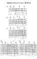
First, the configuration of a medical instrument with an IC chip according to an embodiment of the present invention will be described with reference to FIG. FIG. 1 shows an example of a medical device with an IC chip according to an embodiment. In the present embodiment, a
本実施形態にかかる医療器具1は、ICチップモジュール11により無線通信する機能を有する。具体的には、医療器具1は、筐体10とICチップモジュール11と刃部12とを有する。筐体10は、少なくとも一部に金属部を有する。本実施形態では、筐体10は金属で形成され、筐体10の全部が金属部として機能する。ICチップモジュール11は、二つの導電部材14a、14bとICチップ15とを有する。導電部材14a、14bは、金属で形成され、ICチップ15の両側に配置されている。ICチップ15は、導電部材14a、14bを通して後述されるリーダーライターから電力の供給を受けるようになっている。
The
(筐体:金属部)
図1の枠内の(a)に示すように、金属部(ここでは、筐体10の全部)には、凹部13が形成されている。金属部の材質としては、鋼、鉄、銅、銀、アルミニウムなどを使用できる。また、金属部は、鋼、鉄、銅、銀及びアルミニウムから成る導電材料群から複数選択された複合材を用いてもよい。金属部は、筐体10の一部又は全部を構成する。金属部は、導電部材14a、14bと同一の金属又は同一の金属を含む複合材で形成されていてもよい。
(Case: Metal part)
As shown in (a) in the frame of FIG. 1, a
凹部13は、段差部13a、及び段差部13a内の貫通口13b(スリット、SLT)を有する。図1の(b)は、図1の(a)のA−A断面を含む斜視図である。図1の(c)は、図1の(b)で示した凹部13の段差部13a上にICチップモジュール11を設置した図である。ICチップモジュール11は、凹部13内をラミネートした樹脂シート16を介して接着剤等で段差部13aに固定される。ICチップモジュール11は、樹脂シート16を使用する替わりに樹脂性の接着剤等の絶縁性の部材を使用して段差部13aに固定されてもよい。
この場合で、凹部13内に樹脂材料を充填し、モールドすることによりICチップモジュ
ール11を凹部13から剥離しないように固定することができる。
The
In this case, the
(1)なお、凹部13は、段差部13aを有していなくてもよい。この場合、凹部13は、段差のない貫通口13bを有するスリット(SLT)となる。さらに段差13aの代わりに凹部13上面から貫通口13bまで傾斜したテーパ部を設けることもできる。
(2)また、凹部13は、段差13aがない場合の貫通口13bを貫通させないようにしてもよい。この場合、凹部13は、貫通していない溝13cとなる。
(3)図1の貫通口13bを貫通しない溝13cに代えることができる。その場合、凹部13は、段差13aと溝13cで構成される。
(1) The
(2) Moreover, you may make it the recessed
(3) It can replace with the groove | channel 13c which does not penetrate the through-
凹部13のスリットSLTまたは溝13cの全長L(図1の(a)を参照)は、無線通信に使用される電波の波長λに対してL=λ/n(nは1以上の整数)となる。このとき、該電波を受けた際に凹部13の短手方向の両端間に生じる電圧が最大となる。例えば、全長Lは、リーダーライターから出力される電波の周波数が950MHzの場合には160mmとなり、電波の周波数が2.45GHzの場合には61mmとなる。
The total length L (see FIG. 1A) of the slit SLT or the groove 13c of the
凹部13のスリットSLTまたは溝13cの短手方向の幅W(図1の(a)を参照)は、アンテナとしての所望の利得を得ることができる周波数の幅に関係している。すなわち、凹部13の短手方向の幅を狭くしていくと、アンテナとしての所望の利得を得ることができる周波数の幅が狭くなる。反対に、凹部13のスリットSLTまたは溝13cの短手方向の幅を広くしていくと、アンテナとしての所望の利得を得ることができる周波数の幅が広くなる。但し、凹部13のスリットSLTまたは溝13cの短手方向の幅を広くしすぎると、インピーダンスが大きくなりアンテナの効率が低下するため、凹部13のスリットLTまたは溝13c短手方向の幅は所定以上広くしないことが好ましい。
The width W (see FIG. 1A) of the slit SLT or the groove 13c in the
一般的に、スリットSLT(貫通口13b)は、金型を用いた打ち抜き加工によって形成され、必要に応じて2次加工により整形される。凹部13のスリットSLTの短手方向の幅Wがあまりに狭いと、所望の幅を所定の精度で得ることが困難になる。そこで、レーザ加工によってスリットSLTを形成することが考えられるが、高コスト化を招く。また、スリットSLTの幅Wがあまりに狭いと、貫通口13bに金属片などの異物が引っかかり、アンテナ性能を劣化させるおそれがある。そこで、例えば、無線通信に使用される電波の波長λが950MHzの場合、スリットSLTの幅Wは2〜3mmに加工することが好ましい。スリットSLTだけでなく溝13cも同様に加工することができる。
In general, the slit SLT (through
つまり、凹部13のスリットSLTまたは溝13cの全長Lは、RFIDチップ等のICチップから送信される無線信号の波長をλとしたとき、L=λ/n(nは1以上の整数)で表され、凹部13のスリットSLTまたは溝13cの幅Wは、UHF帯の無線信号を送受信する場合には7〜9mmの範囲内の長さに設定され、2.45GHz帯の無線信号を送受信する場合には2〜3mmの範囲内の長さに設定される。このとき、n=2のときに両端に生じる電圧が最大となる。
That is, the total length L of the slit SLT or the groove 13c of the
また、凹部13のスリットSLTまたは溝13cは直線状のみではなく、屈曲した形状でもよく、スリットSLTまたは溝(13cの全長Lが所定の長さとなっていればよい。例えば、スリットSLTが2か所で屈曲した構成の場合であって、スリットSLTの第1スリット部S1の長さをL1、第2スリット部S2の長さをL2、第3スリット部S3の長さをL3として説明する。第2スリット部S2が第1スリット部S1及び第3スリット部S3の間に位置し、それぞれのスリット部S1、S3と屈曲した状態で両側で隣り合わせて構成され、屈曲した一つのスリットを形成している場合である。この場合、スリットSLTは、次の式が満足されるように形成される。ここで、λは通信に用いられる電波の波長である。たとえば、H型の場合は、横ライン、縦ライン2つ(L1、L2)、縦ラインの間の横ライン(L3)となり、
スリット全長L=L1+L2+L3=λ/n(nは1以上の整数)の関係となっていることが望ましい。つまり、凹部13のスリットSLTまたは溝13cが屈曲していても凹部13のスリットSLTまたは溝13cにおける短手側の両端間に生じる電圧が最大になるように、凹部13ののスリットSLTまたは溝13c全長Lは、L=λ/n(nは1以上の整数)となるように設計されることが好ましい。
In addition, the slit SLT or the groove 13c of the
It is desirable that the slit total length L = L1 + L2 + L3 = λ / n (n is an integer of 1 or more). That is, even if the slit SLT or the groove 13c of the
(ICチップモジュール)
ICチップモジュール11は、通信が可能なRFIDタグであってもよい。図2の(a)及び(b)に示されるように、ICチップモジュール11は、導電部材14a、14bとICチップ15とを有する。導電部材14a、14bは、金属で形成され、ICチップ15の両側に配置されている。つまり、ICチップ15は、導電部材14a、14bに挟まれ、リーダーライターから発信された電波により生じる導電部材14a、14bの電位差によってICチップ15内に電流が流れることで動作可能になっている。
(IC chip module)
The
ICチップ15とリーダーライターとの無線通信に用いられる電波の周波数fは、該電波を受けたときに凹部13の短手方向の貫通口13bにより隔てられた両側の間に生じる起電力Wa及び電圧V、2つの導電部材14a、14bのそれぞれの面積S、絶縁シート16の厚さd、絶縁シート16の誘電率εr、真空の誘電率ε0、及びICチップ15の作動に必要な電力の最小値Wminを用いて、
Wmin≦Wa−4πf・S・ε0・εr・V・2/d
の関係が満足されているRFIDタグである。
The frequency f of the radio wave used for the wireless communication between the
Wmin ≦ Wa-4πf · S · ε 0 · ε r · V · 2 / d
The RFID tag satisfies the above relationship.
導電部材14a、14bは、図2の(a)及び(b)に示される形状に限られない。例えば、導電部材14a、14bの長手方向は、凹部13の長手方向に対して制限されることはないが、凹部13の長手方向の長さより長い部分に関しては電極として作用することはない。このため、導電部材14a、14bの長手方向は、凹部13の長手方向の長さより短い方がよい。また、上式から導電部材14a、14bの面積Sが大きくなるほど、ICチップ15の作動に必要な電力の最小値Wminを小さくすることができる。よって、導電部材14a、14bの接触面積は大きいほうが電力供給に対して有利に働くため、特に凹部13の短手方向が短い場合には、凹部13の短手方向の導電部材14a、14bの長さは、できるだけ長い方がよい。
The
ICチップ15とリーダーライターとの交信周波数としては、一般的には2.45GHz、5.8GHz(マイクロ波)及びUHF帯(例えば、950MHz)などの周波数帯から適宜選択して使用される。ICチップ15のアンテナ回路基板に使用する基材としては、特に制限はなく、目的に応じて適宜選択することができる。例えば、基板は、紙フェノール、ガラスエポキシ、コンポジット等のリジッドタイプ、ポリイミド、ポリエステル、ポリプロピレン、ポリエチレン、ポリスチレン、ナイロン、PET(ポリエチレンテレフタレート)、紙、合成紙等のフレキシブルタイプ及び両者の複合タイプを用いることができる。
In general, the communication frequency between the
前記基材の厚みは、5μm〜360μmが好ましく、加工作業性、コスト等の点から5μm〜100μmがより好ましい。基材をラミネートする金属箔としては、鋼箔、鉄箔、銅箔、銀箔、アルミニウム箔等を使用できる。また、鋼、鉄、銅、銀及びアルミニウムから成る導電材料群から複数選択された複合材からなる箔も用いることもできる。コスト、加工性からアルミニウム箔が好ましく、その厚みは2μm〜50μmが好ましい。形状は、正方形、長方形、台形、円形、楕円形、三角形など、特に制限はない。 The thickness of the substrate is preferably 5 μm to 360 μm, and more preferably 5 μm to 100 μm from the viewpoints of workability and cost. Steel foil, iron foil, copper foil, silver foil, aluminum foil, etc. can be used as the metal foil for laminating the substrate. A foil made of a composite material selected from a plurality of conductive material groups made of steel, iron, copper, silver and aluminum can also be used. Aluminum foil is preferable from the viewpoint of cost and workability, and the thickness is preferably 2 μm to 50 μm. The shape is not particularly limited, such as a square, a rectangle, a trapezoid, a circle, an ellipse, and a triangle.
ICチップ15の厚さ(高さ)は、200μm以下が好ましく、25μm〜140μmがより好ましい。また、ICチップ15を保護するために、ポリイミドフィルム、ポリエステルフィルム、紙等の保護膜を接着させることもできる。前記保護膜の厚さは、10μm〜60μmが好ましい。ICチップ15としては、特に制限はなく、目的に応じて適宜選択することができる。
The thickness (height) of the
(ICチップモジュールの取り付け)
ICチップモジュール11の取り付け方法としては、メス1の金属部に導電部材を取り付ける方法であればよい。医療器具によっては、筐体が樹脂など金属部以外の部材で形成されている場合がある。その場合、ICチップモジュール11は、筐体の一部である金属部の凹部13に取付けられる。
(Installation of IC chip module)
The
図1の(a)に示されるように、ICチップモジュール11は、凹部13の内部であって凹部13の短手方向の両端またはその近傍に導電部材14a、14bが固定される。つまり、ICチップモジュール11は、凹部13の短手方向に沿って貫通口13bを跨いだ状態で凹部13の段差部13a取り付けられる。また、図1の(c)に示されるように、凹部13の段差部13aと導電部材14a、14bとの間には、樹脂シート16が介在する。
As shown in FIG. 1A, in the
ICチップモジュール11を凹部13内に取り付ける際には、例えば、接着剤を用いてもよく、ネジなどによって固定してもよい。ネジで固定する場合には、ICチップモジュール11を図示しない保持プレートに貼り付けた状態で、保持プレートに形成されたネジ穴からネジを挿入し、そのネジで凹部13の段差部13aに保持プレートを固定してもよい。また、凹部13内を樹脂材料でモールドすることで、ICチップモジュール11を凹部13内に埋め込み、固定することもできる。なお、以上の固定方法は、ICチップモジュール11を医療器具の金属部に取り付ける方法の一例にすぎず、これらに限定されない。
When mounting the
ICチップモジュール11をメス1の凹部13に貼り付けるための接着剤としては、ICチップモジュール11を金属部に固定できれば特に限定されない。接着剤として使用可能な樹脂は、目的に応じて適宜選択することができる。接着剤として使用可能な樹脂の材料の一例としては、アクリル、ポリエチレン、ポリプロピレン、ポリスチレン、ポリビニルアルコール、ポリビニルブチラール、ポリウレタン、飽和ポリエステル、不飽和ポリエステル、エポキシ樹脂、フェノール樹脂、ポリカーボネート、ポリアミド等などが挙げられる。これらの中でも、熱、紫外線(UV)、電子線(EB)等を用いて硬化させた樹脂を適宜選択することができ、硬化剤を用いて熱硬化させる樹脂や湿気硬化させる樹脂が特に好ましい。
The adhesive for attaching the
また、ICチップモジュール11が付設された凹部13は、樹脂で充填されてもよい。この場合、ICチップモジュール11上に充填された樹脂の表面は、メス1の筐体10の表面と同一面(フラット)であることが好ましい。ただし、樹脂の表面が筐体10の表面より凹んでいても良く(凹状態)、樹脂の表面が筐体10の表面よりも盛り上がっても良い(凸状態)。いずれの場合にも、ICチップモジュール11が樹脂から突出していないことが好ましい。凹部13に充填する樹脂の材料の一例としては、セラミック、ポリプロピレン、ポリエチレン等の高分子化合物などを使用しても良く、目的に応じて適宜選択することができ、特に制限されない。
Further, the
かかる構成によれば、ICチップモジュール11は、凹部13の貫通口13bを跨いだ状態で、かつ、導電部材14a14bと金属部(ここでは、凹部13の段差部13a)とを絶縁性の部材により離隔した状態で固定される。また、ICチップモジュール11は、凹部13の内部に収納される。ICチップモジュール11を凹部13内に埋設することにより、衝撃によるICチップ15の破損を防止することができる。
According to such a configuration, the
また、凹部13の形状については、ICチップ15が付設でき、交信に必要な長さL及び幅Wの凹みが確保できれば特に制限されない。また、ICチップモジュール11が搭載される深さについても、特に制限されない。
Further, the shape of the
以上、本実施形態にかかるICチップ付き医療器具の一例としてICチップモジュール11が取り付けられたメス1について説明した。なお、メス1に取り付けられたICチップ15は、ICチップ15を識別するための識別情報を内部に記憶している。ICチップ15が記憶する識別情報は、ICチップ15が取り付けられた医療器具の識別情報として使用することができる。よって、本実施形態にかかるICチップ付き医療器具は、通信機能を用いて識別可能な手段を備えた医療器具として機能することができる。
As described above, the
[ICチップ付き医療器具の製造方法]
次に、本実施形態に係るICチップ付き医療器具の製造方法について、図3を参照しながら説明する。図3は、一実施形態に係る医療器具の製造方法の一例を示す。本実施形態では、医療器具としてメス1を例に挙げて、ICチップ15付きメスの製造方法について説明する。
[Method of manufacturing medical device with IC chip]
Next, the manufacturing method of the medical device with an IC chip according to the present embodiment will be described with reference to FIG. Drawing 3 shows an example of the manufacturing method of the medical instrument concerning one embodiment. In the present embodiment, a method for manufacturing a scalpel with an
最初に、図3の(a)に示すように、樹脂部材20上にICチップモジュール11を接着する。樹脂部材20は、予め凹部13に嵌め込むのに適した大きさに形成されている。
First, as shown in FIG. 3A, the
次に、図3の(b)に示すように、ICチップモジュール11を下にした状態の樹脂部材20を、凹部13が形成された金属の台30に嵌め込む。凹部13の段差部13aは樹脂シート16でラミネートされている。これにより、図3の(c)に示すように、樹脂部材20が台30に嵌め込まれたとき、ICチップモジュール11は、絶縁シート16を介して段差部13a上に配置され、これにより、導電部材14a、14bがICチップ15の電極として機能するようになる。
Next, as shown in FIG. 3B, the
本実施形態では、図3の(d)に示すように、メス1の筐体10には矩形状の嵌合部10bが形成されている。台30は、嵌合部10bに嵌め込むのに適した大きさに形成されている。よって、図3の(e)に示すように、台30が嵌合部10bに嵌め込まれると、台30と筐体10とは表面がフラットなICチップ付きメスの金属部となる。
In the present embodiment, as shown in FIG. 3D, a rectangular
この状態で、図3の(e)に示すように、貫通している台30の裏面から貫通口13bに樹脂材料21を充填し、モールドすることにより、ICチップモジュール11を凹部13から剥離しないように固定することができる。
In this state, as shown in FIG. 3E, the
(変形例)
なお、本実施形態に係るICチップ付き医療器具の変形例として、凹部13が溝であり、貫通口を有していない場合を図4に示す。図4の(b)は、図4の(a)のA'−A'断面を含む斜視図である。この場合、ICチップモジュール11は、凹部13内をラミネートした樹脂シート16を介して接着剤等で凹部13に固定される。この場合、凹部13内に樹脂材料を充填し、モールドすることによりICチップモジュール11を凹部13から剥離しないように固定することができる。
(Modification)
As a modification of the medical device with an IC chip according to this embodiment, FIG. 4 shows a case where the
以上、医療器具の金属部に、ICチップモジュール11を取り付ける方法について説明した。以上の製造方法は、メス1にICチップモジュール11を取り付ける場合に限られず、メス1以外の医療器具を製造する際にも同様に適用可能である。以上の製造方法は、例えば、図5に示すように、ハサミ2の筐体10の金属部にICチップモジュール11を取り付ける場合にも使用できる。
The method for attaching the
[医療器具管理システム]
次に、本実施形態に係る医療器具管理システムについて、図6を参照しながら説明する。図6は、一実施形態に係る医療器具管理システムの一例を示す。本実施形態では、医療器具管理システム3は、手術室4で使用される医療器具の管理を行う。
[Medical device management system]
Next, the medical instrument management system according to the present embodiment will be described with reference to FIG. FIG. 6 shows an example of a medical instrument management system according to an embodiment. In the present embodiment, the medical
医療器具管理システム3は、医療器具(図6では、医療器具の一例としてメス1が図示されている)、リーダーライター40及びPC50を有する。メス1には、ICチップモジュール11が取り付けられている。なお、メス1に限らず、本実施形態に係る医療器具管理システム3により管理される医療器具には、すべてICチップモジュール11が取り付けられている。
The medical
周波数帯が長波帯及び短波帯の場合、リーダーライターの送信アンテナコイルとRFIDタグのアンテナコイルとの間の電磁誘導作用によってRFIDタグに電圧が誘起され、この電圧によりICチップが起動され、通信が可能となる。このように電磁誘導方式による通信の場合、RFIDタグはリーダーライターによる誘導電磁界内でしか動作できないため、通信距離は数十cm程度と短い。 When the frequency band is a long wave band or a short wave band, a voltage is induced in the RFID tag by an electromagnetic induction action between the transmission antenna coil of the reader / writer and the antenna coil of the RFID tag, and the IC chip is activated by this voltage to perform communication. It becomes possible. In this way, in the case of communication using the electromagnetic induction method, the RFID tag can only operate within the induction electromagnetic field generated by the reader / writer, and therefore the communication distance is as short as several tens of centimeters.
これに対して、本実施形態で使用されるICチップモジュール11は、リーダーライター40からの電力を受けてこれを電源として駆動してもよい。また、無線通信に使用される周波数帯は、UHF帯及びマイクロ波帯である。よって、本実施形態にかかる医療器具管理システム3では、電波通信方式により、通信距離は1〜8m程度と長い。
On the other hand, the
したがって、本実施形態では、手術室4のゲート5の近傍やゲート5の上方の天井部にリーダーライター40を設置することで、メス1に取り付けられたICチップモジュール11は、人等がゲート5を通過する際、リーダーライター40からの電波をキャッチする。これにより、ICチップモジュール11は、電力の供給を受けて識別情報を含む検知情報をリーダーライター40に送信することができる。なお、手術室4は、医療行為のために医療器具を使用する所定の室の一例であり、所定の室には診察室や検診室等が含まれる。ゲート5は、前記医療行為等が行われる所定の室の出入口に設けられる。ゲート5には、人の出入りを検知するセンサが取り付けられていて、人が入室したか、退室したかを検出できるようになっている。
Therefore, in the present embodiment, the reader /
PC50は、CPU(Central Processing Unit)51、ROM(Read Only Memory)52、RAM(Random Access Memory)53、HDD(Hard Disk Drive)54、カウンター55、タイマー56、入出力I/F(InterFace)57及び通信I/F58を備え、それぞれがバスで相互に接続されている。
The
ROM52は、電源を切っても内部データを保持することができる不揮発性の半導体メモリ(記憶装置)である。ROM52には、OS設定及びネットワーク設定などのプログラムやデータが格納されている。RAM53は、プログラムやデータを一時保持する揮発性の半導体メモリである。HDD54は、プログラムやデータを格納している不揮発性の記憶装置である。格納されるプログラムやデータには、装置全体を制御する基本ソフトウェアであるOS(Operating System)、及びOS上において各種機能を提供するアプリケーションソフトウェアなどがある。
The
CPU51は、上記記憶装置(例えば「HDD54」など)から、プログラムやデータをRAM53上に読み出し、後述される医療器具管理処理を含む処理を実行することで、全体の制御や医療器具の管理機能を実現する演算装置である。
The
カウンター55は、手術室にある医療器具の数をカウントする。タイマー56は、時間を計時する。入出力I/F(InterFace)57は、キーボードやマウス等の入力装置60の操作に応じて入力データを取得し、必要なデータを表示装置61の画面に表示するためのインターフェースである。通信I/F58は、ネットワークを介してリーダーライター40等の外部機器と通信を行うためのインターフェースである。
The counter 55 counts the number of medical instruments in the operating room. The
なお、PC50は、ゲートを通ったICチップ付き医療器具を管理する情報処理装置の一例である。本実施形態に係る情報処理装置は、PC50に限られず、通信機能と情報処理機能を有する装置であれば、タブレット型の端末やその他のどんな端末装置であってもよい。情報処理装置は、リーダーライター40が受信したICチップ15付き医療器具の識別情報に基づき、室内にあるICチップ15付き医療器具を管理する。情報処理装置は、リーダーライター40が受信したICチップ15付き医療器具の識別情報及び医療器具の種別情報に基づき、室内にあるICチップ15付き医療器具を種別毎に管理してもよい。
The
[医療器具管理処理]
次に、本実施形態に係るPC50によって実行される医療器具管理処理について、図7を参照しながら説明する。図7は、一実施形態に係る医療器具管理処理の一例を示すフローチャートである。本実施形態では、医療器具管理システム3は、手術室4で使用されるメス1等の医療器具を管理する。
[Medical device management processing]
Next, a medical instrument management process executed by the
本医療器具管理処理が開始されると、まず、PC50のCPU51は、ゲート5に取り付けられたセンサが人の出入りを検知したかを判定する(ステップS10)。検知していない場合、ステップS10の処理を繰り返す。検知した場合、CPU51は、リーダーライター40を介してゲート5を通ったICチップ付き医療器具の識別情報を含む検知情報を取得し、ログファイルに保存する(ステップS12)。
When this medical instrument management process is started, first, the
例えば、ICチップ付きメス1がゲート5から手術室4の内部に持ち込まれたとき、メス1のICチップモジュール11は、リーダーライター40から発信された電波を受信する(図6(a)の(1))。ICチップモジュール11は、供給された電力を用いて、少なくとも自己の識別情報を含む検知情報をリーダーライター40に送信する(図6(b)の(2))。検知情報には、医療器具の種別情報が含まれることが好ましい。送信された検知情報は、リーダーライター40により読み込まれる。
For example, when the
CPU51は、リーダーライター40により読み込まれ検知情報を通信I/F58を介して取得し、RAM53又はHDD54に保存する(図6(b)の(3))。図8には、RAM53やHDD54に保存された、手術室4に出入りした医療器具の履歴情報を示すログファイルの一例が示される。
The
ログファイルには、医療器具の種別情報80、医療器具の識別情報81(すなわち、ICチップ15の識別情報)、検知情報を取得した時刻情報82、医療器具の所在情報83(1:IN(室内)、0:OUT(室外))が記憶される。本実施形態では、医療器具の種別情報80、医療器具の識別情報81及び医療器具の所在情報83は、メス1に取り付けられたICチップ15から送信された検知情報に含まれる。
The log file includes medical
このように、ICチップ15は、リーダーライター40の通信領域内に入ると、リーダーライター40から発信される電波を受信し、少なくとも自己の識別情報を含む検知情報をリーダーライター40に送信する。これにより、PC50は、リーダーライター40を介して検知情報を取得し、医療器具を管理するためのログファイルを生成することができる。
As described above, when the
図7に戻り、次に、CPU51は、メス1がゲート5から入ったかを判定する(ステップS14)。CPU51は、ログファイルの医療器具の所在情報83が1(IN)の場合、メス1がゲート5から入ったと判定し、カウンター55は、医療器具の数を一つ増やす(ステップS16)。
Returning to FIG. 7, next, the
例えば、図8の(a)に示すように、ログファイルに二つの医療器具の出入りの履歴情報が記憶されている場合、二つのメス1の所在情報83は、共に1(IN)であるため、カウンター55は、メス1の数を「2」と算出する。図8の(b)に示すように、ログファイルに三つの医療器具の出入りの履歴情報が記憶されている場合、二つのメス1及び一つのハサミ2の所在情報83は共に1(IN)である。このとき、カウンター55は、メス1の数を「2」と算出し、ハサミ2の数を「1」と算出する。
For example, as shown in (a) of FIG. 8, when history information of two medical devices is stored in the log file, the
同様にして、メス1が手術室から出た場合についても説明する。まず、CPU51は、ゲート5に取り付けられたセンサが人の出入りを検知したかを判定する(ステップS10)。検知していない場合、ステップS10の処理を繰り返す。検知した場合、CPU51は、リーダーライター40を介してゲート5を通ったICチップ付き医療器具の識別情報を含む検知情報を取得し、ログファイルに保存する(ステップS12)。
Similarly, the case where the
例えば、ICチップ付きメス1がゲート5から手術室4の外部に持ち出されたとき、メス1のICチップモジュール11は、リーダーライター40から発信された電波を受信する(図6(c)の(4))。ICチップモジュール11は、供給された電力を用いて、少なくとも自己の識別情報を含む検知情報をリーダーライター40に送信する(図6(d)の(5))。検知情報には、医療器具の種別情報が含まれることが好ましい。送信された検知情報は、リーダーライター40により読み込まれる。
For example, when the
CPU51は、リーダーライター40により読み込まれ検知情報を通信I/F58を介して取得し、RAM53又はHDD54に保存する(図6(d)の(6))。図8の(c)には、3行目のハサミ2が手術室4から退出した履歴情報が4行目に保存されている。このとき、4行目の所在情報83は、0(OUT)となっている。
The
図7に戻り、次に、CPU51は、メス1がゲート5から入ったかを判定する(ステップS14)。ここでは、メス1がゲート5から出た場合であるのでステップS14では「No」と判定し、ステップS18に進む。ステップS18にて、CPU51は、ログファイルの4行目のハサミ2の所在情報83に基づき、メス1がゲート5から出たと判定する。カウンター55は、ハサミ2の数を一つ減らす(ステップS20)。この結果、ハサミ2の数は「0」と算出される。このとき、メス1の数は「2」と算出されている。ステップS18にて「No」と判定された場合は何もしないか、もしくは、エラーを出力するようにしてもよい。
Returning to FIG. 7, next, the
その後の医療器具の手術室4への出入りに応じた、図7の一実施形態に係る医療器具管理処理の結果、図8の(d1)のログファイルが生成された場合、カウンター55は、メス1及びハサミ2の数を共に「0」と算出する。このとき、CPU51は、手術室4に残っている医療器具はないと判定できる。
When the log file of (d1) of FIG. 8 is generated as a result of the medical instrument management process according to the embodiment of FIG. 7 according to the subsequent entry / exit of the medical instrument into / from the
一方、図8の(d2)のログファイルが生成された場合、カウンター55は、メス1の数を「1」と算出しハサミ2の数を「0」と算出する。このとき、CPU51は、手術室4に識別情報「1111111」のメス1が残っていると判定できる。
On the other hand, when the log file of (d2) in FIG. 8 is generated, the counter 55 calculates the number of
以上、一実施形態にかかるICチップ付き医療器具及び医療器具管理システムについて説明した。これによれば、通信機能を用いて識別可能な医療器具及び該医療器具を管理可能なシステムを提供することができる。 The medical device with an IC chip and the medical device management system according to one embodiment have been described above. According to this, a medical device that can be identified using a communication function and a system that can manage the medical device can be provided.
なお、上記実施形態にて生成されたログファイルに保存されている情報は、表示装置61により表示されてもよい。また、本発明にかかるリーダーライターは、手術用ベッドに内蔵されたアンテナ及び送受信機を含むものでもよいし、器械台装置に内蔵されたアンテナ及び送受信機を含むものでもよい。また、本発明にかかるリーダーライターは、アンテナの死角を無くするため、複数のアンテナ及び送受信機を含むものでもよく、特に限定されない。
Information stored in the log file generated in the above embodiment may be displayed by the
以上に説明したように、上記実施形態にかかる医療器具には、医療器具の個別識別を行うために無線通信により非接触で情報の読み出し及び書き込みが可能なICチップモジュールが取り付けられている。このため、このようなICチップ付き医療器具を、リーダーライターと情報処理装置を有する医療器具管理システムに組み込むことにより、手術前後及び手術中を通して、医療器具の手術室への持ち込み、持ち出しの履歴情報をリアルタイムに保存することができる。そして、履歴情報を記憶したログファイルに基づき、情報処理装置を用いて医療器具の所在を何時でもモニターできる。また、医療器具の管理に関する負担を大幅に減らすことができるとともに、患者の安全性を担保できる。さらに、万が一遺残事故があったときにもICチップモジュールを使って回収操作を誘導できる。 As described above, an IC chip module capable of reading and writing information in a non-contact manner by wireless communication is attached to the medical device according to the above embodiment in order to individually identify the medical device. For this reason, by incorporating such a medical instrument with an IC chip into a medical instrument management system having a reader / writer and an information processing device, history information on bringing the medical instrument into and out of the operating room before and after the operation and during the operation. Can be saved in real time. And based on the log file which memorize | stored historical information, the location of a medical device can be monitored at any time using an information processing apparatus. In addition, the burden on the management of medical devices can be greatly reduced, and patient safety can be ensured. Furthermore, in the unlikely event that there is a remaining accident, the recovery operation can be guided using the IC chip module.
また、アンテナスキャナを含むことによって、遺残された位置の特定が容易に検知できる。さらに、ICチップモジュールを導入することにより、ICチップ付き医療器具の室への出入りがリアルタイムにチェック可能となるため、医療器具が、何時、どの手術場面で使用されたかを容易に知ることができる。たとえ医療器具を紛失したとしても、医療器具を発見する手がかりができ、紛失した際に回収操作が安全に施行できる。また、煩雑な医療器具を手術の準備のためにセットする場合も、個々の種類が管理されており、滅菌処理の有無などに関する管理が容易になる。 Further, by including an antenna scanner, it is possible to easily detect the position of the remaining position. Furthermore, by introducing an IC chip module, it is possible to check the entry / exit of a medical instrument with an IC chip in real time, so that it is easy to know when and in which surgical scene the medical instrument was used. . Even if the medical device is lost, a clue to discover the medical device can be obtained, and the recovery operation can be safely performed when it is lost. In addition, when a complicated medical instrument is set for preparation for surgery, each type is managed, and management regarding the presence or absence of sterilization is facilitated.
以上、ICチップ付き医療器具及び医療器具管理システムについて上記実施形態により説明したが、本発明は上記実施形態に限定されるものではなく、本発明の範囲内で種々の変形及び改良が可能である。 As mentioned above, although the medical device with an IC chip and the medical device management system have been described in the above embodiment, the present invention is not limited to the above embodiment, and various modifications and improvements can be made within the scope of the present invention. .
例えば、本発明の医療器具に形成された凹部の表面及び裏面をモールドする材料として、所望のポリマー(2-メタクリロイルオキシエチルホスホリルコリン)、または、ハイドロキシアパタイト(リン酸カルシウムの一種)を埋め込んでもよい。これらの材料は、交信に影響を生じさせることなく、ICチップが突出せずに、手術等の作業の支障にならないため好ましい。 For example, a desired polymer (2-methacryloyloxyethyl phosphorylcholine) or hydroxyapatite (a kind of calcium phosphate) may be embedded as a material for molding the front and back surfaces of the recess formed in the medical device of the present invention. These materials are preferable because they do not affect the communication, the IC chip does not protrude, and the operation such as surgery is not hindered.
また、上記実施形態では、本発明のICチップ付き医療器具をメスを例に挙げて具体的に説明した。しかしながら、本発明のICチップ付き医療器具は、これに限られず、ハサミ、ピンセット、縫合針、鉗子、ネジ、その他の医療用の器具等の外科手術時に体内に遺残される可能性のある医療器具についても、メスと同様にICチップを取り付けることで、同じ効果を得ることができる。 Moreover, in the said embodiment, the medical device with an IC chip of this invention was concretely demonstrated taking the example of the knife. However, the medical device with an IC chip of the present invention is not limited to this, and a medical device that may remain in the body during a surgical operation such as scissors, tweezers, suture needles, forceps, screws, and other medical devices. The same effect can be obtained by attaching an IC chip similarly to the knife.
1:メス
2:ハサミ
3:医療器具管理システム
4:手術室
5:ゲート
10:筐体
11:ICチップモジュール
12:刃部
13:凹部
13a:段差部
13b:貫通口
14a、14b:導電部材
15:ICチップ
16:樹脂シート
40:リーダーライター
50:PC
51:CPU
60:入力装置
61:表示装置
80:医療器具の種別
81:ICチップの識別情報
83:医療器具の所在情報
1: Female 2: Scissors 3: Medical instrument management system 4: Operating room 5: Gate 10: Housing 11: IC chip module 12: Blade portion 13: Recessed
51: CPU
60: Input device 61: Display device 80: Type of medical instrument 81: Identification information of IC chip 83: Location information of medical instrument
Claims (8)
二つの導電部材が該二つの導電部材を通して電力の供給を受けるICチップの両側に配置されたICチップモジュールと、を有し、
前記ICチップモジュールは、前記凹部の短手方向の両端またはその近傍に前記二つの導電部材が配置されるように取り付けられる、ICチップ付き医療器具。 A housing having at least a part of a metal part in which a predetermined recess is formed;
An IC chip module having two conductive members disposed on both sides of an IC chip to which power is supplied through the two conductive members;
The IC chip module is a medical device with an IC chip attached so that the two conductive members are disposed at or near both ends of the recess in the short direction.
請求項1に記載のICチップ付き医療器具。 The recess penetrates,
The medical device with an IC chip according to claim 1.
前記ICチップモジュールは、前記段差部に樹脂材料を介して固定され、前記凹部の内部に収納される、
請求項1又は2に記載のICチップ付き医療器具。 The recess has a stepped portion,
The IC chip module is fixed to the stepped portion via a resin material, and is housed in the recess.
The medical device with an IC chip according to claim 1 or 2.
請求項1〜3のいずれか一項に記載のICチップ付き医療器具。 The IC chip module is embedded in the recess by molding the recess with a resin material.
The medical device with an IC chip according to any one of claims 1 to 3.
請求項1〜4のいずれか一項に記載のICチップ付き医療器具。 The metal part is formed of the same metal as the two conductive members or a composite material containing the same metal,
The medical device with an IC chip according to any one of claims 1 to 4.
請求項1〜5のいずれか一項に記載のICチップ付き医療器具。 The overall length L of the recess is L = λ / n (n is an integer of 1 or more) with respect to the wavelength λ of the radio wave transmitted from the reader / writer that communicates wirelessly with the IC chip module.
The medical device with an IC chip according to any one of claims 1 to 5.
前記ICチップ付き医療器具は、
所定の凹部が形成された金属部を少なくとも一部に有する筐体と、
二つの導電部材が該二つの導電部材を通して電力の供給を受けるICチップの両側に配置されたICチップモジュールと、を有し、
前記ICチップモジュールは、前記凹部の短手方向の両端またはその近傍に前記二つの導電部材が配置されるように取り付けられ、
前記ICチップは、前記リーダーライターから電力の供給を受けて前記ICチップ付き医療器具の識別情報を含む検知情報を該リーダーライターに送信し、
前記情報処理装置は、前記リーダーライターが受信した検知情報に含まれる前記ICチップ付き医療器具の識別情報に基づき、前記ICチップ付き医療器具を管理する、
医療器具管理システム。 A medical instrument management system comprising: an information processing apparatus; a medical instrument with an IC chip having an IC chip module; and a reader / writer that communicates wirelessly with the IC chip module,
The medical device with the IC chip is:
A housing having at least a part of a metal part in which a predetermined recess is formed;
An IC chip module having two conductive members disposed on both sides of an IC chip to which power is supplied through the two conductive members;
The IC chip module is attached so that the two conductive members are arranged at or near both ends in the short direction of the recess,
The IC chip is supplied with electric power from the reader / writer and transmits detection information including identification information of the medical device with the IC chip to the reader / writer,
The information processing apparatus manages the medical device with an IC chip based on identification information of the medical device with an IC chip included in the detection information received by the reader / writer.
Medical instrument management system.
前記情報処理装置は、所定の室の出入口に設けられたゲートを通って前記ICチップ付き医療器具が該室内に持ち込まれる又は該室内から持ち出される際、前記リーダーライターが受信した検知情報に含まれるICチップ付き医療器具の識別情報及び種別情報に基づき、前記室内のICチップ付き医療器具を種別毎に管理する、
請求項7に記載された医療器具管理システム。 The detection information includes identification information and type information of the medical device with the IC chip,
The information processing apparatus is included in detection information received by the reader / writer when the medical device with an IC chip is brought into or taken out of the room through a gate provided at an entrance of a predetermined room. Based on the identification information and type information of the medical device with IC chip, to manage the medical device with IC chip in the room for each type,
The medical instrument management system according to claim 7.
Priority Applications (1)
| Application Number | Priority Date | Filing Date | Title |
|---|---|---|---|
| JP2015054356A JP2015192863A (en) | 2014-03-18 | 2015-03-18 | Medical appliance with ic chip, and medical appliance management system |
Applications Claiming Priority (3)
| Application Number | Priority Date | Filing Date | Title |
|---|---|---|---|
| JP2014054475 | 2014-03-18 | ||
| JP2014054475 | 2014-03-18 | ||
| JP2015054356A JP2015192863A (en) | 2014-03-18 | 2015-03-18 | Medical appliance with ic chip, and medical appliance management system |
Publications (1)
| Publication Number | Publication Date |
|---|---|
| JP2015192863A true JP2015192863A (en) | 2015-11-05 |
Family
ID=52823450
Family Applications (1)
| Application Number | Title | Priority Date | Filing Date |
|---|---|---|---|
| JP2015054356A Pending JP2015192863A (en) | 2014-03-18 | 2015-03-18 | Medical appliance with ic chip, and medical appliance management system |
Country Status (4)
| Country | Link |
|---|---|
| US (1) | US20150265360A1 (en) |
| EP (1) | EP2929853A3 (en) |
| JP (1) | JP2015192863A (en) |
| CN (1) | CN105095932A (en) |
Cited By (2)
| Publication number | Priority date | Publication date | Assignee | Title |
|---|---|---|---|---|
| JP2019084012A (en) * | 2017-11-06 | 2019-06-06 | 株式会社トータルItシステムジャパン | Installation method of ic tag and ic tag built-in metal body |
| JP2019185494A (en) * | 2018-04-12 | 2019-10-24 | 株式会社トータルItシステムジャパン | Ic tag attachment method and ic tag built-in metal body |
Families Citing this family (11)
| Publication number | Priority date | Publication date | Assignee | Title |
|---|---|---|---|---|
| US8600478B2 (en) | 2007-02-19 | 2013-12-03 | Medtronic Navigation, Inc. | Automatic identification of instruments used with a surgical navigation system |
| GB2487950A (en) * | 2011-02-10 | 2012-08-15 | Samuel George | Cutting implement with protective sheath |
| US9901367B2 (en) * | 2014-03-05 | 2018-02-27 | Spectra Medical Devices, Inc. | Safety scalpel |
| DE102016121478A1 (en) * | 2016-11-09 | 2018-05-09 | Aesculap Ag | Surgical instrument with RFID tag |
| CN106779387A (en) * | 2016-12-08 | 2017-05-31 | 杭州电子科技大学 | A kind of operating theater instruments and its management system |
| USD860455S1 (en) * | 2017-04-20 | 2019-09-17 | Elie Levy | Ergonomic scalpel |
| CN108498188A (en) * | 2018-04-28 | 2018-09-07 | 北京中芯医源科技有限公司 | Medical surgical instrument and its application method can be traced |
| US20210204936A1 (en) * | 2018-05-14 | 2021-07-08 | The General Hospital Corporation | Wireless-enabled surgical suture needle |
| DE102019122349A1 (en) | 2019-08-20 | 2021-02-25 | Aesculap Ag | Integrated RFID tag holder |
| DE102020116932A1 (en) * | 2020-06-26 | 2021-12-30 | Aesculap Ag | Medical instrument with transponder installation module and medical transponder communication system |
| CN112966802A (en) * | 2021-03-12 | 2021-06-15 | 四川大学华西医院 | Medical instrument based on radio frequency identification and medical instrument identification system |
Family Cites Families (13)
| Publication number | Priority date | Publication date | Assignee | Title |
|---|---|---|---|---|
| CA2456424C (en) * | 2001-08-08 | 2011-09-27 | Stryker Corporation | Surgical cutting accessory with internal memory |
| JP2003111772A (en) | 2001-10-03 | 2003-04-15 | Sakase Chemical Industry Co Ltd | System for managing surgical instrument |
| US7764178B2 (en) * | 2003-03-03 | 2010-07-27 | Veroscan, Inc. | Interrogator and interrogation system employing the same |
| US7253736B2 (en) * | 2004-08-26 | 2007-08-07 | Sdgi Holdings, Inc. | RFID tag for instrument handles |
| US20060244597A1 (en) * | 2005-04-28 | 2006-11-02 | Sdgi Holdings, Inc. | Surgical instrument tray RFID tag |
| US7362228B2 (en) * | 2005-04-28 | 2008-04-22 | Warsaw Orthepedic, Inc. | Smart instrument tray RFID reader |
| US7837694B2 (en) * | 2005-04-28 | 2010-11-23 | Warsaw Orthopedic, Inc. | Method and apparatus for surgical instrument identification |
| JP4870989B2 (en) * | 2006-01-07 | 2012-02-08 | ケイ・アール・ディコーポレーション株式会社 | WORKING TOOL AND WORKING TOOL DATA RECORDING DEVICE |
| US8624721B2 (en) * | 2006-04-17 | 2014-01-07 | Warsaw Orthopedic, Inc. | Method and apparatus for embedding a transmitter into a tool, and a system for monitoring the tool |
| TWI457832B (en) * | 2006-09-26 | 2014-10-21 | Toppan Printing Co Ltd | Rfid information media and object attached with the media |
| US20080132882A1 (en) * | 2006-11-30 | 2008-06-05 | Howmedica Osteonics Corp. | Orthopedic instruments with RFID |
| FR2954088B1 (en) * | 2009-12-22 | 2011-12-30 | Philippe Laheurte | MEDICAL DEVICE EQUIPPED WITH RFID IDENTIFICATION MODULE |
| JP5790518B2 (en) | 2012-01-25 | 2015-10-07 | 新日鐵住金株式会社 | Product tag for metal products |
-
2015
- 2015-03-17 EP EP15159476.9A patent/EP2929853A3/en not_active Withdrawn
- 2015-03-17 US US14/659,947 patent/US20150265360A1/en not_active Abandoned
- 2015-03-18 CN CN201510423948.2A patent/CN105095932A/en active Pending
- 2015-03-18 JP JP2015054356A patent/JP2015192863A/en active Pending
Cited By (2)
| Publication number | Priority date | Publication date | Assignee | Title |
|---|---|---|---|---|
| JP2019084012A (en) * | 2017-11-06 | 2019-06-06 | 株式会社トータルItシステムジャパン | Installation method of ic tag and ic tag built-in metal body |
| JP2019185494A (en) * | 2018-04-12 | 2019-10-24 | 株式会社トータルItシステムジャパン | Ic tag attachment method and ic tag built-in metal body |
Also Published As
| Publication number | Publication date |
|---|---|
| CN105095932A (en) | 2015-11-25 |
| US20150265360A1 (en) | 2015-09-24 |
| EP2929853A2 (en) | 2015-10-14 |
| EP2929853A3 (en) | 2016-01-20 |
Similar Documents
| Publication | Publication Date | Title |
|---|---|---|
| JP2015192863A (en) | Medical appliance with ic chip, and medical appliance management system | |
| US20240152865A1 (en) | System, apparatus and methods for counting and detecting surgical sponges | |
| US9220574B2 (en) | Tissue marker | |
| US5664582A (en) | Method for detecting, distinguishing and counting objects | |
| US11065081B2 (en) | Sterilizable wirelessly detectable objects for use in medical procedures and methods of making same | |
| US5456718A (en) | Apparatus for detecting surgical objects within the human body | |
| CN106037742B (en) | Pad-based antenna and heater system for use during medical procedures | |
| ES2553885T3 (en) | Method and system to associate an absorbent article with a user | |
| US9940569B2 (en) | RFID tag assembly and surgical instrument | |
| US7589634B2 (en) | Auxiliary antenna array for system for detecting foreign objects in a surgical patient | |
| WO2016188959A1 (en) | Surgical container contents detection system | |
| CA2260703A1 (en) | Disposal container for detecting, distinguishing and counting objects | |
| WO2009006800A1 (en) | Medical products | |
| US8690068B2 (en) | Miniaturized UHF RFID tag for implantable medical device | |
| EP1538982A1 (en) | Detection system | |
| US20050035861A1 (en) | Identification apparatus for medically related technical accessories and patients | |
| Li et al. | Battery free smart bandage based on NFC RFID technology | |
| WO2007042872A1 (en) | Gauze or the like having a device for its detection at a distance | |
| EP0747016B1 (en) | Electromagnetically detectable marked surgical object | |
| JP2005102803A (en) | Leaving object accident preventing medical appliance and system | |
| Hosaka et al. | Automatic identification for surgical instruments using UHF band passive RFID | |
| ES2554990B1 (en) | Wireless controlled deactivation tag, manufacturing method and method and system for using said tag | |
| RU2435181C2 (en) | Method and system for associating absorbing article with user | |
| JP2013255114A (en) | Design method for medical rfid tag and medical rfid tag, and sanitary material with rfid tag | |
| US20190339316A1 (en) | Device for measuring radioelectric dose on a surface, in particular for measuring the radiological dose of a patient during a radiology operation |