JP2015190850A - Error estimation method, kinematic analysis method, error estimation device, and program - Google Patents
Error estimation method, kinematic analysis method, error estimation device, and program Download PDFInfo
- Publication number
- JP2015190850A JP2015190850A JP2014068226A JP2014068226A JP2015190850A JP 2015190850 A JP2015190850 A JP 2015190850A JP 2014068226 A JP2014068226 A JP 2014068226A JP 2014068226 A JP2014068226 A JP 2014068226A JP 2015190850 A JP2015190850 A JP 2015190850A
- Authority
- JP
- Japan
- Prior art keywords
- sensor
- detection result
- unit
- moving body
- error
- Prior art date
- Legal status (The legal status is an assumption and is not a legal conclusion. Google has not performed a legal analysis and makes no representation as to the accuracy of the status listed.)
- Pending
Links
- 238000000034 method Methods 0.000 title claims abstract description 85
- 238000004458 analytical method Methods 0.000 title description 93
- 238000001514 detection method Methods 0.000 claims abstract description 137
- 239000011159 matrix material Substances 0.000 claims abstract description 129
- 238000006243 chemical reaction Methods 0.000 claims abstract description 54
- 230000009466 transformation Effects 0.000 claims description 93
- 230000001133 acceleration Effects 0.000 claims description 85
- 238000012545 processing Methods 0.000 abstract description 139
- 230000009184 walking Effects 0.000 description 100
- 238000005259 measurement Methods 0.000 description 82
- 230000008569 process Effects 0.000 description 41
- 230000010354 integration Effects 0.000 description 26
- 238000004891 communication Methods 0.000 description 19
- 238000012937 correction Methods 0.000 description 11
- 238000010586 diagram Methods 0.000 description 11
- 230000008859 change Effects 0.000 description 9
- 230000005021 gait Effects 0.000 description 7
- 230000006870 function Effects 0.000 description 5
- 230000000694 effects Effects 0.000 description 4
- 230000015654 memory Effects 0.000 description 3
- 230000004048 modification Effects 0.000 description 3
- 238000012986 modification Methods 0.000 description 3
- 230000009183 running Effects 0.000 description 3
- 238000005070 sampling Methods 0.000 description 3
- 230000008901 benefit Effects 0.000 description 2
- 238000005265 energy consumption Methods 0.000 description 2
- 238000011156 evaluation Methods 0.000 description 2
- 230000005484 gravity Effects 0.000 description 2
- 238000012805 post-processing Methods 0.000 description 2
- 230000003416 augmentation Effects 0.000 description 1
- 230000009194 climbing Effects 0.000 description 1
- 239000002131 composite material Substances 0.000 description 1
- 239000000470 constituent Substances 0.000 description 1
- 230000001351 cycling effect Effects 0.000 description 1
- 230000003247 decreasing effect Effects 0.000 description 1
- 238000010790 dilution Methods 0.000 description 1
- 239000012895 dilution Substances 0.000 description 1
- 238000005401 electroluminescence Methods 0.000 description 1
- 210000003414 extremity Anatomy 0.000 description 1
- JCYWCSGERIELPG-UHFFFAOYSA-N imes Chemical compound CC1=CC(C)=CC(C)=C1N1C=CN(C=2C(=CC(C)=CC=2C)C)[C]1 JCYWCSGERIELPG-UHFFFAOYSA-N 0.000 description 1
- 230000009191 jumping Effects 0.000 description 1
- 239000004973 liquid crystal related substance Substances 0.000 description 1
- 230000007246 mechanism Effects 0.000 description 1
- 239000002245 particle Substances 0.000 description 1
- 230000009182 swimming Effects 0.000 description 1
- 230000017105 transposition Effects 0.000 description 1
- 210000000707 wrist Anatomy 0.000 description 1
Images


Landscapes
- Navigation (AREA)
- Position Fixing By Use Of Radio Waves (AREA)
Abstract
【課題】処理負荷を低減し、かつ、測位用衛星からの信号を利用して移動体の状態を表す指標の誤差を精度よく推定することが可能な誤差推定方法等を提供すること。【解決手段】移動体の移動を伴う運動の周期における所定のタイミングで、前記移動体に取り付けられた第1センサーを基準とする第1座標系と前記移動体を基準とする第2座標系との間の座標変換行列を算出することと、測位用衛星からの信号を受信する第2センサーの検出結果が得られた場合に、前記座標変換行列を用いて、前記第1センサーの検出結果に基づく前記移動体の方位角及び前記第2センサーの検出結果に基づく前記移動体の方位角のいずれか一方を変換することと、前記第2センサーの検出結果が得られたタイミング以降の前記所定のタイミングで、変換した前記方位角と他方の前記方位角との差を用いて、前記移動体の状態を表す指標の誤差を推定することと、を含む、誤差推定方法。【選択図】図10An object of the present invention is to provide an error estimation method and the like that can reduce a processing load and can accurately estimate an error of an index representing a state of a moving object using a signal from a positioning satellite. A first coordinate system with a first sensor attached to the moving body as a reference and a second coordinate system with the moving body as a reference at a predetermined timing in a cycle of movement accompanying the movement of the moving body. When the detection result of the second sensor that receives the signal from the positioning satellite is obtained, the detection result of the first sensor is calculated using the coordinate conversion matrix. Converting one of the azimuth angle of the mobile body based on the detection result of the second sensor and the azimuth angle of the mobile body based on the detection result of the second sensor, and the predetermined time after the timing when the detection result of the second sensor is obtained An error estimation method comprising: estimating an error of an index representing the state of the moving object using a difference between the converted azimuth angle and the other azimuth angle at timing. [Selection] Figure 10
Description
本発明は、誤差推定方法、運動解析方法、誤差推定装置及びプログラムに関する。 The present invention relates to an error estimation method, a motion analysis method, an error estimation device, and a program.
複数のセンサーを内蔵したセンサーモジュールを歩行者に装着し、センサーモジュールの検出結果を用いて歩行者の位置や方位を推定する技術が知られている。センサーを用いた位置や方位の推定においては、GPS(Global Positioning System)を演算結果の補正等に利用することが多い。例えば、特許文献1では、歩行時に、身体の最高位置到着点あるいは着地地点を基準に移動方向を決定して位置を算出し、GPSを利用して位置を補正する手法が提案されている。
A technique is known in which a sensor module incorporating a plurality of sensors is attached to a pedestrian, and the position and orientation of the pedestrian are estimated using the detection result of the sensor module. In estimating the position and direction using a sensor, GPS (Global Positioning System) is often used for correction of calculation results. For example,
しかしながら、例えば腰部にセンサーモジュールを装着した場合、歩行やランニング時には腰が左右に揺れることが多いため、計測された方位角は腰の揺れに応じて、進行方向を中心に左右対称の分布になる。これに対して、GPSを利用して算出される方位角は歩行者の進行方向とほぼ一致するため、これら2つの方位角の差は時々刻々変化する。そのため、GPSを利用して算出される方位角を、計測された方位角のリファレンスとして使用しても、方位角の計測誤差を正しく推定することができるとは限らない。誤差を正しく推定するためには、腰部の方位角と進行方向とのずれの情報、つまり、センサーを基準とする座標系と歩行者を基準とする座標系との間の変換行列を計算する必要がある。しかしながら、GPSの測位情報が得られるタイミングが不定のため、GPSの測位情報が得られたタイミングで、直近の速度の情報をもとに座標変換行列を毎回計算しなければならない。そのため、処理負荷が大きくなるほか、時間の経過とともに積分誤差等による速度の誤差が増加して座標変換行列を正しく算出することができない場合もあり、方位角誤差の推定精度が低下するという問題があった。 However, for example, when the sensor module is attached to the waist, the hips often sway left and right during walking and running, so the measured azimuth is symmetrically distributed around the direction of travel according to the sway of the waist. . On the other hand, since the azimuth angle calculated using the GPS substantially coincides with the traveling direction of the pedestrian, the difference between these two azimuth angles changes every moment. Therefore, even if an azimuth angle calculated using GPS is used as a reference for the measured azimuth angle, an azimuth angle measurement error cannot always be correctly estimated. In order to correctly estimate the error, it is necessary to calculate information on the deviation between the azimuth angle of the waist and the direction of travel, that is, the transformation matrix between the coordinate system based on the sensor and the coordinate system based on the pedestrian There is. However, since the timing at which GPS positioning information is obtained is indefinite, the coordinate transformation matrix must be calculated every time based on the latest speed information at the timing at which GPS positioning information is obtained. As a result, the processing load increases, and the error in speed due to integration error etc. increases with time, and the coordinate transformation matrix may not be calculated correctly. there were.
本発明は、以上のような問題点に鑑みてなされたものであり、本発明のいくつかの態様によれば、処理負荷を低減し、かつ、測位用衛星からの信号を利用して移動体の状態を表す指標の誤差を精度よく推定することが可能な誤差推定方法、誤差推定装置及びプログラム、並びに、ユーザーの運動を精度よく解析することが可能な運動解析方法を提供することができる。 The present invention has been made in view of the above-described problems, and according to some aspects of the present invention, a mobile object can be obtained by reducing the processing load and using a signal from a positioning satellite. It is possible to provide an error estimation method, an error estimation device and a program capable of accurately estimating an error of an index representing the state of the above, and a motion analysis method capable of accurately analyzing a user's motion.
本発明は前述の課題の少なくとも一部を解決するためになされたものであり、以下の態様または適用例として実現することが可能である。 SUMMARY An advantage of some aspects of the invention is to solve at least a part of the problems described above, and the invention can be implemented as the following aspects or application examples.
[適用例1]
本適用例に係る誤差推定方法は、移動体の移動を伴う運動の周期における所定のタイミングで、前記移動体に取り付けられた第1センサーを基準とする第1座標系と前記移動体を基準とする第2座標系との間の座標変換行列を算出することと、測位用衛星からの信号を受信する第2センサーの検出結果が得られた場合に、前記座標変換行列を用いて、前記第1センサーの検出結果に基づく前記移動体の方位角及び前記第2センサーの検出結果に
基づく前記移動体の方位角のいずれか一方を変換することと、前記第2センサーの検出結果が得られたタイミング以降の前記所定のタイミングで、変換した前記方位角と他方の前記方位角との差を用いて、前記移動体の状態を表す指標の誤差を推定することと、を含む。
[Application Example 1]
The error estimation method according to this application example is based on a first coordinate system based on a first sensor attached to the moving body and the moving body at a predetermined timing in a cycle of movement accompanied by movement of the moving body. Calculating the coordinate transformation matrix between the second coordinate system and the second sensor receiving the signal from the positioning satellite, and using the coordinate transformation matrix when the detection result of the second sensor is obtained. One of the azimuth angle of the moving body based on the detection result of one sensor and the azimuth angle of the moving body based on the detection result of the second sensor is converted, and the detection result of the second sensor is obtained. Estimating an error of an index representing the state of the moving object using a difference between the converted azimuth angle and the other azimuth angle at the predetermined timing after the timing.
本適用例に係る誤差推定方法では、移動体の移動を伴う運動の周期毎の所定のタイミングでは、第1センサーの検出結果に基づく方位角と第2センサーの検出結果に基づく方位角との差がほぼ一定であることを利用する。当該所定のタイミングで算出した座標変換行列を用いて、第2センサーの検出結果が得られたタイミング以降の所定のタイミングで算出した、この2つの方位角の差を用いて移動体の状態を表す指標の誤差を推定する。従って、本適用例に係る誤差推定方法によれば、第2センサーの検出結果が得られるタイミングが不定であっても、誤差を精度よく推定できるとともに、第2センサーの検出結果が得られる毎に座標変換行列を算出する必要もないので、処理負荷を低減させることができる。 In the error estimation method according to this application example, the difference between the azimuth angle based on the detection result of the first sensor and the azimuth angle based on the detection result of the second sensor at a predetermined timing for each cycle of movement accompanied by movement of the moving body. Is used to be almost constant. Using the coordinate transformation matrix calculated at the predetermined timing, the state of the moving body is expressed using the difference between the two azimuth angles calculated at a predetermined timing after the timing at which the detection result of the second sensor is obtained. Estimate the error of the indicator. Therefore, according to the error estimation method according to this application example, the error can be accurately estimated even when the timing at which the detection result of the second sensor is obtained is indefinite, and every time the detection result of the second sensor is obtained. Since it is not necessary to calculate a coordinate transformation matrix, the processing load can be reduced.
[適用例2]
上記適用例に係る誤差推定方法において、前記第1センサーの検出結果を用いて、前記第1座標系での前記移動体の速度を算出し、算出した前記速度に基づいて前記座標変換行列を算出してもよい。
[Application Example 2]
In the error estimation method according to the application example, the speed of the moving body in the first coordinate system is calculated using the detection result of the first sensor, and the coordinate transformation matrix is calculated based on the calculated speed. May be.
本適用例に係る誤差推定方法によれば、第2センサーの検出結果の有無に関係なく、運動の周期の所定のタイミングで座標変換行列を算出することができる。 According to the error estimation method according to this application example, the coordinate transformation matrix can be calculated at a predetermined timing of the motion period regardless of the presence or absence of the detection result of the second sensor.
[適用例3]
上記適用例に係る誤差推定方法において、前記所定のタイミングは、前記第1センサーの検出結果が所定の条件を満たしたタイミングであってもよい。
[Application Example 3]
In the error estimation method according to the application example, the predetermined timing may be a timing at which a detection result of the first sensor satisfies a predetermined condition.
本適用例に係る誤差推定方法によれば、第1センサーの検出結果が所定の条件を満たしたタイミングを基準とすることで、運動の周期において、座標変換行列を算出したタイミングに対応するタイミングで誤差を精度よく推定することができる。 According to the error estimation method according to this application example, with the timing at which the detection result of the first sensor satisfies a predetermined condition as a reference, the timing corresponding to the timing at which the coordinate transformation matrix is calculated in the period of motion. The error can be estimated accurately.
[適用例4]
上記適用例に係る誤差推定方法は、さらに、前記第1センサーの検出結果を用いて、前記周期を検出することを含み、前記所定のタイミングは、前記周期を検出したタイミングであってもよい。
[Application Example 4]
The error estimation method according to the application example further includes detecting the period using a detection result of the first sensor, and the predetermined timing may be a timing at which the period is detected.
本適用例に係る誤差推定方法によれば、運動の周期を検出したタイミングで座標変換行列を算出し、その後、運動の周期を検出したタイミングで誤差を精度よく推定することができる。 According to the error estimation method according to this application example, the coordinate transformation matrix can be calculated at the timing when the motion period is detected, and then the error can be accurately estimated at the timing when the motion cycle is detected.
[適用例5]
上記適用例に係る誤差推定方法において、前記移動体が移動を開始してから所定の期間における前記第1センサーの検出結果を用いて前記座標変換行列を算出してもよい。
[Application Example 5]
In the error estimation method according to the application example, the coordinate transformation matrix may be calculated using a detection result of the first sensor in a predetermined period after the moving body starts moving.
本適用例に係る誤差推定方法によれば、移動体が移動を開始してから早いうちに座標変換行列を算出するので、積分誤差等により生じる座標変換行列の誤差を低減させ、誤差の推定精度を向上させることができる。 According to the error estimation method according to this application example, since the coordinate transformation matrix is calculated as soon as the moving object starts moving, the error of the coordinate transformation matrix caused by an integration error or the like is reduced, and the error estimation accuracy is reduced. Can be improved.
[適用例6]
上記適用例に係る誤差推定方法は、さらに、前記移動体が直進しているか否かを判定す
ることを含み、前記第2センサーの検出結果が得られたタイミングから次の前記所定のタイミングまでの間に、前記移動体が直進していないと判定した場合には、当該次の前記所定のタイミングでは前記誤差を推定しなくてもよい。
[Application Example 6]
The error estimation method according to the application example further includes determining whether or not the moving body is traveling straight, and from the timing at which the detection result of the second sensor is obtained to the next predetermined timing. In the meantime, when it is determined that the moving body is not moving straight, the error need not be estimated at the next predetermined timing.
本適用例に係る誤差推定方法によれば、前記第2センサーの検出結果が得られてから次の所定のタイミングまでに移動体が進行方向を変えると、当該所定のタイミングでは、第1センサーの検出結果に基づく方位角と第2センサーの検出結果に基づく方位角との差が、座標変換行列の算出時とは異なってしまうことを考慮し、このような場合には誤差を推定しないので、誤差の推定精度の低下を抑制することができる。 According to the error estimation method according to this application example, when the moving body changes the traveling direction by the next predetermined timing after the detection result of the second sensor is obtained, at the predetermined timing, the first sensor Considering that the difference between the azimuth angle based on the detection result and the azimuth angle based on the detection result of the second sensor is different from the calculation time of the coordinate transformation matrix, in such a case, the error is not estimated. A decrease in error estimation accuracy can be suppressed.
[適用例7]
上記適用例に係る誤差推定方法において、前記第1センサーは、加速度センサー及び角速度センサーの少なくとも一方を含んでもよい。
[Application Example 7]
In the error estimation method according to the application example, the first sensor may include at least one of an acceleration sensor and an angular velocity sensor.
本適用例に係る誤差推定方法によれば、加速度センサーあるいは角速度センサーの検出結果に基づく方位角と第2センサーの検出結果に基づく方位角との差を用いて、移動体の状態を表す指標の誤差を推定することができる。 According to the error estimation method according to this application example, using the difference between the azimuth angle based on the detection result of the acceleration sensor or the angular velocity sensor and the azimuth angle based on the detection result of the second sensor, The error can be estimated.
[適用例8]
上記適用例に係る誤差推定方法において、前記第1センサーは、地磁気センサーであってもよい。
[Application Example 8]
In the error estimation method according to the application example, the first sensor may be a geomagnetic sensor.
本適用例に係る誤差推定方法によれば、地磁気センサーの検出結果に基づく方位角と第2センサーの検出結果に基づく方位角との差を用いて、移動体の状態を表す指標の誤差を推定することができる。 According to the error estimation method according to this application example, using the difference between the azimuth angle based on the detection result of the geomagnetic sensor and the azimuth angle based on the detection result of the second sensor, the error of the index representing the state of the moving object is estimated. can do.
[適用例9]
本適用例に係る運動解析方法は、上記のいずれかの誤差推定方法を用いて前記誤差を推定することと、推定した前記誤差を用いて、前記指標を補正することと、補正した前記指標を用いて、前記移動体の運動を解析することと、を含む。
[Application Example 9]
The motion analysis method according to this application example includes estimating the error using any one of the error estimation methods described above, correcting the index using the estimated error, and correcting the corrected index. And analyzing the movement of the moving body.
本適用例に係る運動解析方法によれば、上記適用例に係る誤差推定方法を用いて推定した移動体の状態を表す指標の誤差を用いて精度よく補正された指標を用いて移動体の運動を精度よく解析することができる。 According to the motion analysis method according to this application example, the motion of the mobile object using the index accurately corrected using the error of the index representing the state of the mobile object estimated using the error estimation method according to the application example described above. Can be analyzed with high accuracy.
[適用例10]
本適用例に係る誤差推定装置は、移動体の移動を伴う運動の周期における所定のタイミングで、前記移動体に取り付けられた第1センサーを基準とする第1座標系と前記移動体を基準とする第2座標系との間の座標変換行列を算出する座標変換行列算出部と、測位用衛星からの信号を受信する第2センサーの検出結果が得られた場合に、前記座標変換行列を用いて、前記第1センサーの検出結果に基づく前記移動体の方位角及び前記第2センサーの検出結果に基づく前記移動体の方位角のいずれか一方を変換する方位角変換部と、前記第2センサーの検出結果が得られたタイミング以降の前記所定のタイミングで、変換した前記方位角と他方の前記方位角との差を用いて、前記移動体の状態を表す指標の誤差を推定する誤差推定部と、を含む。
[Application Example 10]
The error estimation apparatus according to this application example uses the first coordinate system with the first sensor attached to the moving body as a reference and the moving body as a reference at a predetermined timing in a cycle of movement accompanying the movement of the moving body. When the detection result of the coordinate conversion matrix calculation unit for calculating the coordinate conversion matrix between the second coordinate system and the second sensor for receiving the signal from the positioning satellite is obtained, the coordinate conversion matrix is used. An azimuth angle conversion unit that converts either the azimuth angle of the mobile body based on the detection result of the first sensor or the azimuth angle of the mobile body based on the detection result of the second sensor; and the second sensor An error estimator that estimates an error of an index representing the state of the moving object using a difference between the converted azimuth angle and the other azimuth angle at the predetermined timing after the timing when the detection result is obtained And including
本適用例に係る誤差推定装置は、移動体の移動を伴う運動の周期毎の所定のタイミングでは、第1センサーの検出結果に基づく方位角と第2センサーの検出結果に基づく方位角との差がほぼ一定であることを利用する。当該所定のタイミングで算出した座標変換行列を用いて、第2センサーの検出結果が得られたタイミング以降の所定のタイミングで算出
した、この2つの方位角の差を用いて、移動体の状態を表す指標の誤差を推定する。従って、本適用例に係る誤差推定装置によれば、第2センサーの検出結果が得られるタイミングが不定であっても、誤差を精度よく推定できるとともに、第2センサーの検出結果が得られる毎に座標変換行列を算出する必要もないので、処理負荷を低減させることができる。
The error estimation device according to this application example is configured such that the difference between the azimuth angle based on the detection result of the first sensor and the azimuth angle based on the detection result of the second sensor at a predetermined timing for each period of movement accompanied by movement of the moving body. Is used to be almost constant. Using the coordinate transformation matrix calculated at the predetermined timing, the difference between the two azimuth angles calculated at a predetermined timing after the timing when the detection result of the second sensor is obtained is used to determine the state of the moving body. Estimate the error of the index to represent. Therefore, according to the error estimation device according to this application example, the error can be accurately estimated even when the timing at which the detection result of the second sensor is obtained is indefinite, and every time the detection result of the second sensor is obtained. Since it is not necessary to calculate a coordinate transformation matrix, the processing load can be reduced.
[適用例11]
本適用例に係るプログラムは、移動体の移動を伴う運動の周期における所定のタイミングで、前記移動体に取り付けられた第1センサーを基準とする第1座標系と前記移動体を基準とする第2座標系との間の座標変換行列を算出することと、測位用衛星からの信号を受信する第2センサーの検出結果が得られた場合に、前記座標変換行列を用いて、前記第1センサーの検出結果に基づく前記移動体の方位角及び前記第2センサーの検出結果に基づく前記移動体の方位角のいずれか一方を変換することと、前記第2センサーの検出結果が得られたタイミング以降の前記所定のタイミングで、変換した前記方位角と他方の前記方位角との差を用いて、前記移動体の状態を表す指標の誤差を推定することと、をコンピューターに実行させる。
[Application Example 11]
The program according to this application example has a first coordinate system based on the first sensor attached to the moving body and a first reference based on the moving body at a predetermined timing in a cycle of movement accompanied by movement of the moving body. When the coordinate transformation matrix between the two coordinate systems is calculated and the detection result of the second sensor that receives the signal from the positioning satellite is obtained, the first sensor is used by using the coordinate transformation matrix. After converting the azimuth angle of the moving body based on the detection result of the moving object and the azimuth angle of the moving body based on the detection result of the second sensor, and after the timing when the detection result of the second sensor is obtained The computer is caused to estimate an error of an index representing the state of the moving body using the difference between the converted azimuth angle and the other azimuth angle at the predetermined timing.
本適用例に係るプログラムは、移動体の移動を伴う運動の周期毎の所定のタイミングでは、第1センサーの検出結果に基づく方位角と第2センサーの検出結果に基づく方位角との差がほぼ一定であることを利用する。当該所定のタイミングで算出した座標変換行列を用いて、第2センサーの検出結果が得られたタイミング以降の所定のタイミングで算出した、この2つの方位角の差を用いて、移動体の状態を表す指標の誤差を推定する。従って、本適用例に係るプログラムによれば、第2センサーの検出結果が得られるタイミングが不定であっても、誤差を精度よく推定できるとともに、第2センサーの検出結果が得られる毎に座標変換行列を算出する必要もないので、処理負荷を低減させることができる。 In the program according to this application example, the difference between the azimuth angle based on the detection result of the first sensor and the azimuth angle based on the detection result of the second sensor is almost equal at a predetermined timing for each cycle of movement accompanied by movement of the moving body. Take advantage of being constant. Using the coordinate transformation matrix calculated at the predetermined timing, the difference between the two azimuth angles calculated at a predetermined timing after the timing when the detection result of the second sensor is obtained is used to determine the state of the moving body. Estimate the error of the index to represent. Therefore, according to the program according to this application example, the error can be accurately estimated even when the timing at which the detection result of the second sensor is obtained is indeterminate, and coordinate conversion is performed every time the detection result of the second sensor is obtained. Since it is not necessary to calculate a matrix, the processing load can be reduced.
以下、本発明の好適な実施形態について図面を用いて詳細に説明する。なお、以下に説明する実施の形態は、特許請求の範囲に記載された本発明の内容を不当に限定するものではない。また以下で説明される構成の全てが本発明の必須構成要件であるとは限らない。 DESCRIPTION OF EMBODIMENTS Hereinafter, preferred embodiments of the present invention will be described in detail with reference to the drawings. The embodiments described below do not unduly limit the contents of the present invention described in the claims. Also, not all of the configurations described below are essential constituent requirements of the present invention.
1.運動解析システム
1−1.システムの概要
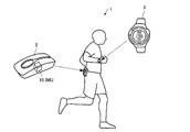
図1は、本実施形態の運動解析システム1の概要について説明するための図である。図
1に示すように、本実施形態の運動解析システム1は、運動解析装置2及び表示装置3を含んで構成されている。運動解析装置2は、ユーザー(移動体の一例)の胴体部分(例えば、右腰又は左腰)に装着される。運動解析装置2は、慣性計測ユニット(IMU:Inertial Measurement Unit)10を内蔵し、ユーザーの歩行(走行も含む)における動きを捉えて、速度、位置、姿勢角(ロール角、ピッチ角、ヨー角)等を計算し、さらに、ユーザーの運動を解析して運動解析情報を生成する。本実施形態では、ユーザーが静止している状態で、慣性計測ユニット(IMU)10の1つの検出軸(以下ではz軸とする)が重力加速度方向(鉛直下向き)とほぼ一致するように、運動解析装置2が装着される。運動解析装置2は、生成した運動解析情報を表示装置3に送信する。
1. Motion analysis system 1-1. Overview of System FIG. 1 is a diagram for describing an overview of a
表示装置3は、リスト型(腕時計型)の携帯情報機器であり、ユーザーの手首等に装着される。ただし、表示装置3は、ヘッドマウントディスプレイ(HMD:Head Mount Display)やスマートフォン等の携帯情報機器であってもよい。ユーザーは、表示装置3を操作して運動解析装置2による計測のスタートやストップを指示することができる。表示装置3は、計測スタートや計測ストップを指示するコマンドを運動解析装置2に送信する。運動解析装置2は、計測スタートのコマンドを受信すると、慣性計測ユニット(IMU)10による計測を開始し、計測結果に基づきユーザーの運動を解析し、運動解析情報を生成する。運動解析装置2は生成した運動解析情報を表示装置3に送信し、表示装置3は運動解析情報を受信し、受信した運動解析情報を文字、図形、音等の各種の形態でユーザーに提示する。ユーザーは表示装置3を介して運動解析情報を認識することができる。
The
なお、運動解析装置2と表示装置3との間のデータ通信は、無線通信でもよいし、有線通信でもよい。
Data communication between the
本実施形態では、以下において、運動解析装置2がユーザーの歩行速度を推定して移動経路や移動時間等を含む運動解析情報を生成する場合を例に挙げて詳細に説明するが、本実施形態の運動解析システム1は、歩行以外の移動を伴う運動における運動解析情報を生成する場合にも、同様に適用することができる。
In the present embodiment, a case where the
1−2.座標系
以下の説明において必要となる座標系を定義する。
・eフレーム(Earth Center Earth Fixed Frame):地球の中心を原点とし、自転軸に平行にz軸をとった右手系の三次元直交座標
・nフレーム(Navigation Frame):移動体(ユーザー)を原点とし、x軸を北、y軸を東、z軸を重力方向とした三次元直交座標系
・bフレーム(Body Frame):センサー(慣性計測ユニット(IMU)10)を基準とする三次元直交座標系
・mフレーム(Moving Frame):移動体(ユーザー)を原点とし、移動体(ユーザー)の進行方向をx軸とした右手系の三次元直交座標系
1-2. Coordinate system The coordinate system required in the following description is defined.
・ E Frame (Earth Center Earth Fixed Frame): 3D Cartesian coordinates of right-handed system with the center of the earth as the origin and the z axis parallel to the rotation axis ・ n Frame (Navigation Frame): Origin of the moving object (user) 3D Cartesian coordinate system with x-axis as north, y-axis as east, and z-axis as gravity direction ・ B frame (Body Frame): 3D Cartesian coordinates based on sensor (Inertial Measurement Unit (IMU) 10) System • m Frame (Moving Frame): A right-handed three-dimensional Cartesian coordinate system with the moving body (user) as the origin and the traveling direction of the moving body (user) as the x-axis
1−3.システムの構成
図2は、運動解析装置2及び表示装置3の構成例を示す機能ブロック図である。図2に示すように、運動解析装置2(誤差推定装置の一例)は、慣性計測ユニット(IMU)10、処理部20、記憶部30、通信部40及びGPSユニット50を含んで構成されている。ただし、本実施形態の運動解析装置2は、これらの構成要素の一部を削除又は変更し、あるいは、他の構成要素を追加した構成であってもよい。
1-3. System Configuration FIG. 2 is a functional block diagram showing a configuration example of the
慣性計測ユニット10(第1センサーの一例)は、加速度センサー12、角速度センサー14及び信号処理部16を含んで構成されている。
The inertial measurement unit 10 (an example of a first sensor) includes an
加速度センサー12は、互いに交差する(理想的には直交する)3軸方向の各々の加速度を検出し、検出した3軸加速度の大きさ及び向きに応じたデジタル信号(加速度データ)を出力する。
The
角速度センサー14は、互いに交差する(理想的には直交する)3軸方向の各々の角速度を検出し、計測した3軸角速度の大きさ及び向きに応じたデジタル信号(角速度データ)を出力する。
The
信号処理部16は、加速度センサー12と角速度センサー14から、それぞれ加速度データと角速度データを受け取って時刻情報を付して不図示の記憶部に記憶し、記憶した加速度データと角速度データに時刻情報を付して所定のフォーマットに合わせたセンシングデータを生成し、処理部20に出力する。
The
加速度センサー12及び角速度センサー14は、それぞれ3軸が、慣性計測ユニット10を基準とするセンサー座標系(bフレーム)の3軸と一致するように取り付けられるのが理想的だが、実際には取り付け角の誤差が生じる。そこで、信号処理部16は、取り付け角誤差に応じてあらかじめ算出された補正パラメーターを用いて、加速度データ及び角速度データをセンサー座標系(bフレーム)のデータに変換する処理を行う。なお、信号処理部16の代わりに後述する処理部20が当該変換処理を行ってもよい。
The
さらに、信号処理部16は、加速度センサー12及び角速度センサー14の温度補正処理を行ってもよい。なお、信号処理部16の代わりに後述する処理部20が当該温度補正処理を行ってもよいし、加速度センサー12及び角速度センサー14に温度補正の機能が組み込まれていてもよい。
Further, the
加速度センサー12と角速度センサー14は、アナログ信号を出力するものであってもよく、この場合は、信号処理部16が、加速度センサー12の出力信号と角速度センサー14の出力信号をそれぞれA/D変換してセンシングデータを生成すればよい。
The
GPSユニット50(第2センサーの一例)は、測位用衛星の一種であるGPS衛星から送信されるGPS衛星信号を受信し、当該GPS衛星信号を利用して測位計算を行ってnフレームにおけるユーザーの位置及び速度(大きさと向きを含むベクトル)を算出し、これらに時刻情報や測位精度情報を付したGPSデータを処理部20に出力する。なお、GPSを利用して、位置や速度を算出する方法や時刻情報を生成する方法については公知であるため、詳細な説明を省略する。
The GPS unit 50 (an example of a second sensor) receives a GPS satellite signal transmitted from a GPS satellite that is a type of positioning satellite, performs a positioning calculation using the GPS satellite signal, and performs a positioning calculation of the user in n frames. The position and speed (vector including magnitude and direction) are calculated, and GPS data with time information and positioning accuracy information added thereto is output to the
処理部20は、例えば、CPU(Central Processing Unit)、DSP(Digital Signal Processor)、ASIC(Application Specific Integrated Circuit)等により構成され、記憶部30に記憶されている各種プログラムに従って、各種の演算処理や制御処理を行う。特に、処理部20は、慣性計測ユニット10からセンシングデータを受け取り、GPSユニット50からGPSデータを受け取り、センシングデータとGPSデータとを用いてユーザーの速度、位置、姿勢角等を算出する。また、処理部20は、算出したこれらの情報を用いて各種の演算処理を行ってユーザーの運動を解析し、移動経路や移動時間等を含む運動解析情報(画像データ、テキストデータ音データ等)を生成する。そして、処理部20は、生成した運動解析情報を、通信部40を介して表示装置3に送信する。
The
記憶部30は、例えば、ROM(Read Only Memory)やフラッシュROM、RAM(Random Access Memory)等の各種ICメモリーやハードディスクやメモリーカードなどの記録媒体等により構成される。
The
記憶部30には、処理部20によって読み出され、運動解析処理(図10参照)を実行するための運動解析プログラム300が記憶されている。
The
また、記憶部30には、センシングデータテーブル310、GPSデータテーブル320、算出データテーブル330、座標変換行列340及び運動解析情報350等が記憶される。
The
センシングデータテーブル310は、処理部20が慣性計測ユニット10から受け取ったセンシングデータ(慣性計測ユニット10の検出結果)を時系列に記憶するデータテーブルである。図3は、センシングデータテーブル310の構成例を示す図である。図3に示すように、センシングデータテーブル310は、慣性計測ユニット10の検出時刻311、加速度センサー12により検出された加速度312及び角速度センサー14により検出された角速度313が対応付けられたセンシングデータが時系列に並べられて構成される。処理部20は、計測を開始すると、サンプリング周期Δt(例えば、20ms)の経過毎に、センシングデータテーブル310に新たなセンシングデータを付加する。さらに、処理部20は、拡張カルマンフィルターを用いた誤差推定(後述)により推定された加速度バイアス及び角速度バイアスを用いて加速度及び角速度を補正し、補正後の加速度及び角速度を上書きしてセンシングデータテーブル310を更新する。
The sensing data table 310 is a data table that stores sensing data (detection results of the inertial measurement unit 10) received by the
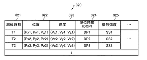
GPSデータテーブル320は、処理部20がGPSユニット50から受け取ったGPSデータ(GPSユニット(GPSセンサー)50の検出結果)を時系列に記憶するデータテーブルである。図4は、GPSデータテーブル320の構成例を示す図である。図4に示すように、GPSデータテーブル320は、GPSユニット50が測位計算を行った時刻321、測位計算により算出した位置322、測位計算により算出した速度323、測位精度(DOP(Dilution of Precision))324、受信したGPS衛星信号の信号強度325等が対応付けられたGPSデータが時系列に並べられて構成される。処理部20は、計測を開始すると、GPSデータを取得する毎に(センシングデータの取得タイミングとは非同期に)、新たなGPSデータを付加してGPSデータテーブル320を更新する。
The GPS data table 320 is a data table that stores the GPS data (the detection result of the GPS unit (GPS sensor) 50) received by the
算出データテーブル330は、処理部20がセンシングデータを用いて算出した速度、位置及び姿勢角を時系列に記憶するデータテーブルである。図5は、算出データテーブル330の構成例を示す図である。図5に示すように、算出データテーブル330は、処理部20が計算した時刻331、速度332、位置333及び姿勢角334が対応付けられた算出データが時系列に並べられて構成される。処理部20は、計測を開始すると、新たにセンシングデータを取得する毎に、すなわち、サンプリング周期Δtの経過毎に、速度、位置及び姿勢角を算出し、算出データテーブル330に新たな算出データを付加する。さらに、処理部20は、拡張カルマンフィルターを用いた誤差推定により推定された速度誤差、位置誤差及び姿勢角誤差を用いて、速度、位置及び姿勢角を補正し、補正後の速度、位置及び姿勢角を上書きして算出データテーブル330を更新する。
The calculated data table 330 is a data table that stores the speed, position, and attitude angle calculated by the
座標変換行列340は、bフレームとmフレームとの間の座標変換を行うための行列であり、後述するように、処理部20がユーザーの歩行運動の周期における所定のタイミングで算出し、記憶部30に保存(記憶)する。
The coordinate
運動解析情報350は、ユーザーの運動に関する各種情報であり、本実施形態では、処理部20が算出した、歩行による移動に関する情報、歩行運動の評価指標に関する情報、歩行に関するアドバイス、指導、警告等の情報を含む。
The
通信部40は、表示装置3の通信部140との間でのデータ通信を行うものであり、処
理部20が生成した運動解析情報を受け取って表示装置3に送信する処理、表示装置3から送信されたコマンド(計測スタート/ストップのコマンド等)を受信して処理部20に送る処理等を行う。
The
表示装置3は、処理部120、記憶部130、通信部140、操作部150、計時部160、表示部170及び音出力部180を含んで構成されている。ただし、本実施形態の表示装置3は、これらの構成要素の一部を削除又は変更し、あるいは、他の構成要素を追加した構成であってもよい。
The
処理部120は、記憶部130に記憶されているプログラムに従って、各種の演算処理や制御処理を行う。例えば、処理部120は、操作部150から受け取った操作データに応じた各種処理(計測スタート/ストップのコマンドを通信部140に送る処理や操作データに応じた表示処理や音出力処理等)、通信部140から運動解析情報を受け取って表示部170や音出力部180に送る処理、計時部160から受け取った時刻情報に応じた時刻画像データを生成して表示部170に送る処理等を行う。
The
記憶部130は、例えば、処理部120が各種処理を行うためのプログラムやデータが記憶されるROMや処理部120の作業領域となるRAM等の各種ICメモリーにより構成される。
The
通信部140は、運動解析装置2の通信部40との間でのデータ通信を行うものであり、処理部120から操作データに応じたコマンド(計測スタート/ストップのコマンド等)を受け取って運動解析装置2に送信する処理、運動解析装置2から送信された運動解析情報(画像データ、テキストデータ、音データ等の各種データ)を受信して処理部120に送る処理等を行う。
The
操作部150は、ユーザーからの操作データ(計測スタート/ストップ、表示内容の選択等の操作データ)を取得し、処理部120に送る処理を行う。操作部150は、例えば、タッチパネル型ディスプレイ、ボタン、キー、マイクなどであってもよい。
The
計時部160は、年、月、日、時、分、秒等の時刻情報を生成する処理を行う。計時部160は、例えば、リアルタイムクロック(RTC:Real Time Clock)ICなどで実現される。
The
表示部170は、処理部120から送られてきた画像データやテキストデータを、文字、グラフ、表、アニメーション、その他の画像として表示するものである。表示部170は、例えば、LCD(Liquid Crystal Display)、有機EL(Electroluminescence)ディスプレイ、EPD(Electrophoretic Display)等のディスプレイで実現され、タッチパネル型ディスプレイであってもよい。なお、1つのタッチパネル型ディスプレイで操作部150と表示部170の機能を実現するようにしてもよい。
The
音出力部180は、処理部120から送られてきた音データを、音声やブザー音等の音として出力するものである。音出力部180は、例えば、スピーカーやブザーなどで実現される。
The
図6は、運動解析装置2の処理部20の構成例を示す機能ブロック図である。本実施形態では、処理部20は、記憶部30に記憶されている運動解析プログラム300を実行することにより、バイアス除去部210、積分処理部220、誤差推定部230、歩行検出部240、直進判定部250、座標変換行列算出部260、方位角変換部270、座標変換部280及び運動解析部290として機能する。
FIG. 6 is a functional block diagram illustrating a configuration example of the
バイアス除去部210は、新たに取得したセンシングデータに含まれる加速度(3軸加速度)及び角速度から、それぞれ、誤差推定部230が推定した加速度バイアスba及び角速度バイアスbωを減算し、加速度及び角速度を補正する処理を行う。なお、計測開始直後の初期状態では加速度バイアスba及び角速度バイアスbωが存在しないため、バイアス除去部210は、ユーザーの初期状態は静止状態であるものとして、慣性計測ユニットからのセンシングデータを用いて、初期バイアスを計算する。
積分処理部220は、バイアス除去部210が補正した加速度及び角速度からeフレームの速度ve、位置pe及び姿勢角(ロール角φbe、ピッチ角θbe、ヨー角ψbe)を算出する処理を行う。具体的には、積分処理部220は、まず、ユーザーの初期状態は静止状態であるものとして、初期速度をゼロとし、あるいは、GPSデータに含まれる速度から初期速度を算出し、さらに、GPSデータに含まれる位置から初期位置を算出する。また、積分処理部220は、バイアス除去部210が補正したbフレームの3軸加速度から重力加速度の向きを特定してロール角φbeとピッチ角θbeの初期値を算出するとともに、GPSデータに含まれる速度からヨー角ψbeの初期値を算出し、eフレームの初期姿勢角とする。GPSデータが得られない場合はヨー角ψbeの初期値を例えばゼロとする。そして、積分処理部220は、算出した初期姿勢角から式(1)で表されるbフレームからeフレームへの座標変換行列(回転行列)Cb eの初期値を算出する。
Integration processing unit 220, the processing

その後は、積分処理部220は、バイアス除去部210が補正した3軸角速度を積算(回転演算)して座標変換行列Cb eを算出し、式(2)より姿勢角を算出する。
Then, the integration processing section 220, the integrated three-axis angular velocity
また、積分処理部220は、座標変換行列Cb eを用いて、バイアス除去部210が補正したbフレームの3軸加速度をeフレームの3軸加速度に変換し、重力加速度成分を除去して積算することでeフレームの速度veを算出する。また、積分処理部220は、eフレームの速度veを積算してeフレームの位置peを算出する。
Further, the integration processing unit 220 uses the coordinate transformation matrix C b e, the 3-axis acceleration of b frames
また、積分処理部220は、誤差推定部230が推定した速度誤差δve、位置誤差δpe及び姿勢角誤差εeを用いて、速度ve、位置pe及び姿勢角を補正する処理も行う。
Performing addition, the integration processing section 220, speed error .delta.v e the
さらに、積分処理部220は、bフレームからmフレームへの座標変換行列Cb m及び
eフレームからmフレームへの座標変換行列Ce mも算出する。これらの座標変換行列は座標変換情報として後述する座標変換部280の座標変換処理に用いられる。
Furthermore, the integration processing unit 220 also calculates a coordinate conversion matrix C b m from the b frame to the m frame and a coordinate conversion matrix C e m from the e frame to the m frame. These coordinate transformation matrices are used as coordinate transformation information for coordinate transformation processing of the coordinate transformation unit 280 described later.
誤差推定部230は、積分処理部220が算出した速度・位置、姿勢角、バイアス除去部210が補正した加速度や角速度、及び、後述する方位角変換部270が算出したリファレンスの方位角を用いて、ユーザーの状態を表す指標の誤差を推定する。本実施形態では、速度、姿勢角、加速度、角速度及び位置をユーザーの状態を表す指標とし、誤差推定部230は、拡張カルマンフィルターを用いてこれらの指標の誤差を推定する。すなわち、誤差推定部230は、積分処理部220が算出した速度veの誤差(速度誤差)δve、積分処理部220が算出した姿勢角の誤差(姿勢角誤差)εe、加速度バイアスba、角速度バイアスbω及び積分処理部220が算出した位置peの誤差(位置誤差)δpeを拡張カルマンフィルターの状態変数とし、状態ベクトルXを式(3)のように定義する。
The
誤差推定部230は、拡張カルマンフィルターの予測式を用いて、状態ベクトルXに含まれる状態変数(ユーザーの状態を表す指標の誤差)を予測する。拡張カルマンフィルターの予測式は、式(4)のように表される。式(4)において、行列Φは、前回の状態ベクトルXと今回の状態ベクトルXを関連付ける行列であり、その要素の一部は姿勢角や位置等を反映しながら時々刻々変化するように設計される。また、Qはプロセスノイズを表す行列であり、その各要素はあらかじめ適切な値に設定される。また、Pは状態変数の誤差共分散行列である。
The
また、誤差推定部230は、拡張カルマンフィルターの更新式を用いて、予測した状態変数(ユーザーの状態を表す指標の誤差)を更新(補正)する。拡張カルマンフィルターの更新式は、式(5)のように表される。Z及びHはそれぞれ観測ベクトル及び観測行列であり、更新式(5)は、実際の観測ベクトルZと状態ベクトルXから予測されるベクトルHXとの差を用いて、状態ベクトルXを補正することを表している。Rは、観測誤差の共分散行列であり、あらかじめ決められた一定値であってもよいし、動的に変更してもよい。Kはカルマンゲインであり、Rが小さいほどKが大きくなる。式(5)より、Kが大きい(Rが小さい)ほど、状態ベクトルXの補正量が大きくなり、その分、Pが小さくなる。
Further, the
本実施形態では、誤差推定部230は、慣性計測ユニットの検出結果から算出される方位角とGPSデータから算出される慣性計測ユニット10の方位角が等しく、かつ、GPSデータから算出される慣性計測ユニット10の方位角は真の方位角(リファレンスの方位角)であるとの条件のもと、慣性計測ユニットの検出結果から算出される方位角とGPSデータから算出される慣性計測ユニット10の方位角との差を観測ベクトルZとして拡張カルマンフィルターを適用し、状態ベクトルXを推定する。
In this embodiment, the
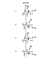
ところで、ユーザーが歩行動作(直進)をする場合、進行方向はほぼ一定であるのに対して、慣性計測ユニット10の姿勢はユーザーの動きに応じて周期的に変化する。図7は、運動解析装置2(IMU10)を右腰に装着したユーザーが歩行動作(直進)をする場合のユーザーの移動を俯瞰した図である。図7に示すように、ユーザーの歩行動作に伴い、ユーザーに対する慣性計測ユニット10の姿勢が随時変化する。ユーザーが右足を踏み出した状態では、図7中の(2)や(4)に示すように、慣性計測ユニット10は進行方向(mフレームのx軸)に対して右側に傾いた姿勢となる。それに対して、ユーザーが左足を踏み出した状態では、図7中の(1)や(3)に示すように、慣性計測ユニット10は進行方向(mフレームのx軸)に対して左側に傾いた姿勢となる。
By the way, when the user performs a walking motion (straight forward), the traveling direction is substantially constant, whereas the posture of the
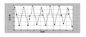
つまり、慣性計測ユニット10の方位角は、ユーザーの歩行動作に伴い、左右1歩ずつの2歩毎に周期的に変化することになり、そのため、慣性計測ユニット10の検出結果から算出される方位角も周期的に変化する。これに対して、ユーザーの進行方向はほぼ一定であるので、GPSデータから算出される方位角はほぼ一定である。図8は、ユーザーが歩行動作(直進)をする場合の慣性計測ユニット10の方位角と進行方向の方位角の一例を示す図であり、横軸は時間、縦軸は方位角である。図8において、実線は、慣性計測ユニット10の方位角を表し、破線は進行方向の方位角を表す。図8に示すように、慣性計測ユニット10の方位角は2歩毎に周期的に変化し、例えば、右足を踏み出した状態で極大となり(○で表記)、左足を踏み出した状態で極小となっている(●で表記)。一方、進行方向の方位角はほとんど変わらずほぼ一定であるため、GPSデータから算出される方位角もほぼ一定である。
In other words, the azimuth angle of the
従って、状態ベクトルXを推定するための上記条件を成立させるためには、慣性計測ユニットの方位角とGPSデータから算出される進行方向の方位角との差の情報、すなわち、bフレームとmフレームとの間の座標変換行列Cm bを計算する必要がある。ところが、図8に示すように、GPSデータが得られるタイミングは不定であるため、GPSデータが得られたタイミングでは、慣性計測ユニット10の方位角(△で表記)とGPSデータから算出される方位角(□で表記)との差は一定とならない。そのため、GPSデータが得られたタイミングで拡張カルマンフィルターによる誤差推定を行うためには、GPSデータが得られる毎に座標変換行列Cm bを計算しなければならず、処理負荷が増大するという問題が生じる。
Therefore, in order to establish the above condition for estimating the state vector X, information on the difference between the azimuth angle of the inertial measurement unit and the azimuth angle in the traveling direction calculated from the GPS data, that is, b frame and m frame it is necessary to calculate the coordinate transformation matrix C m b between. However, as shown in FIG. 8, since the timing at which GPS data is obtained is indefinite, at the timing at which GPS data is obtained, the azimuth (indicated by Δ) of the
そこで、本実施形態では、ユーザーの歩行動作に伴い、慣性計測ユニット10の方位角
が2歩毎に周期的に変化することを利用し、歩行周期における所定のタイミングで座標変換行列Cm bを一度だけ計算し、その後は、GPSデータが得られる毎に、歩行周期における次の所定のタイミング(座標変換行列Cm bを計算した時と同じタイミング)で、座標変換行列Cm bを用いてリファレンスの方位角を算出し、状態ベクトルXを推定する。このようにすれば、GPSデータが得られる毎に、座標変換行列Cm bを再計算する必要がなくなり、処理負荷を大幅に削減することができる。
Therefore, in this embodiment, as the user's walking motion, the azimuth angle of the
なお、GPSデータが得られたタイミングから、歩行周期における次の所定のタイミングまでの間に、ユーザーが進行方向を変えた場合、GPS方位角と慣性計測ユニットの方位角との差が、座標変換行列の算出時とは異なってしまう。そのため、当該所定のタイミングでは、直近に得られたGPSデータから算出したリファレンスの方位角を使用すると状態ベクトルXの推定精度が大きく低下するおそれがある。そこで、本実施形態では、ユーザーが直進しているか否かを判定し、GPSデータが得られたタイミングから、歩行周期における次の所定のタイミングまでの間に、ユーザーが進行方向を変えた場合には、当該所定のタイミングでは状態ベクトルXの推定を行わないようにする。 Note that if the user changes the direction of travel between the timing at which GPS data is obtained and the next predetermined timing in the walking cycle, the difference between the GPS azimuth and the azimuth of the inertial measurement unit is coordinate transformed. This is different from the matrix calculation. Therefore, at the predetermined timing, if the reference azimuth calculated from the most recently obtained GPS data is used, the estimation accuracy of the state vector X may be greatly reduced. Therefore, in the present embodiment, it is determined whether or not the user is traveling straight, and when the user changes the traveling direction from the timing when the GPS data is obtained to the next predetermined timing in the walking cycle. Does not estimate the state vector X at the predetermined timing.
図6に戻り、歩行検出部240は、慣性計測ユニット10の検出結果(具体的には、バイアス除去部210が補正したセンシングデータ)を用いて、ユーザーの歩行周期(歩行タイミング)として2歩(左右1歩ずつ)の周期を検出する処理を行う。図9は、ユーザーの歩行時に慣性計測ユニット10が検出した3軸加速度の合成加速度の一例を示す図である。図9において、横軸は時間であり、縦軸は合成加速度の値である。図9に示すように、合成加速度は周期的に変化しており、合成加速度が極小値から極大値になる中間のタイミングは、図8の方位角が極大又は極小となるタイミングと一致する。従って、歩行検出部240は、例えば、合成加速度の極大値と極小値との差(振幅)が閾値以上の場合に、合成加速度が極小値から極大値になる中間のタイミングの1回おきに歩行周期を検出することができる。例えば、歩行検出部240は、直近に合成加速度が極小値から極大値(あるいは、極大値から極小値)に変化した時の中間値を保存しておき、その中間値を超えた時(図9中の○)に1回おきに歩行周期を検出してもよい。
Returning to FIG. 6, the walking
直進判定部250は、ユーザーが直進中か否かを判定する処理を行う。例えば、直進判定部250は、バイアス除去部210が補正した加速度の向きの変化が一定範囲内であるか否かにより直進判定を行ってもよいし、積分処理部220が算出した速度の向きの変化や姿勢角の変化に基づき直進判定を行ってもよい。
The straight
座標変換行列算出部260は、ユーザーの歩行周期における所定のタイミングで、bフレーム(第1座標系の一例)とmフレーム(第2座標系の一例)との間の座標変換行列Cm bを算出し、算出した座標変換行列Cm bを図2の座標変換行列340として記憶部30に記憶する処理を行う。ここで、所定のタイミングは、慣性計測ユニット10の検出結果が所定の条件を満たしたタイミングであり、具体的には、歩行検出部240が歩行周期を検出したタイミングである。本実施形態では、座標変換行列算出部260は、慣性計測ユニット10の検出結果(具体的には、バイアス除去部210が補正した加速度)から重力加速度を除去して積分し、bフレームでのユーザーの進行方向の速度Vb=(Vbx,Vby,Vbz)を算出する。そして、座標変換行列算出部260は、算出した速度Vbに基づいて、以下のように座標変換行列Cm bを算出する。
Coordinate transformation
bフレームでの速度Vb=(Vbx,Vby,Vbz)とmフレームでの速度Vm=(Vmx,Vmy,Vmz)との関係は、座標変換行列Cm bを用いて式(6)のように表される。なお、直進歩行であるので、式(6)では、Vmy=Vmz=0としている。 b frames at the rate Vb = (Vbx, Vby, Vbz ) speed Vm at m frames and = (Vmx, Vmy, Vmz) relationship with, as the equation (6) using the coordinate transformation matrix C m b expressed. Since this is a straight line, Vmy = Vmz = 0 in equation (6).
式(6)より、慣性計測ユニット10のmフレームに対するロール角φbm、ピッチ角θbm、ヨー角ψbmは、式(7)で表される。なお、本実施形態では、ロール角φbmを計算することはできず、また、ユーザーの歩行時にはヨー角ψbmの変化に対してロール角φbmの変化は十分小さいので、式(7)ではφbm=0に近似している。
From the equation (6), the roll angle φ bm , the pitch angle θ bm , and the yaw angle ψ bm for the m frame of the
式(7)のロール角φbm、ピッチ角θbm、ヨー角ψbmを用いて、式(8)により座標変換行列Cm bを計算することができる。式(8)において、Rz(−ψbm)は、z軸まわりに−ψbm回転する回転行列である。また、Ry(−θbm)は、y軸まわりに−θbm回転する回転行列である。また、Rx(−φbm)は、x軸まわりに−φbm回転する回転行列である。 Roll angle phi bm of formula (7), the pitch angle theta bm, using yaw angle [psi bm, can be calculated coordinate transformation matrix C m b by equation (8). In Expression (8), R z (−ψ bm ) is a rotation matrix that rotates about −z bm around the z axis. R y (−θ bm ) is a rotation matrix that rotates about −y bm around the y axis. R x (−φ bm ) is a rotation matrix that rotates about −x bm around the x axis.
本実施形態では、座標変換行列算出部260は、ユーザーが歩行を開始してから所定の期間における慣性計測ユニット10の検出結果を用いて座標変換行列Cm bを算出する。ここで、所定の期間は、例えば、ユーザーが数歩進む期間であり、座標変換行列算出部260は、ユーザーが歩行開始後の数歩において、歩行検出部240が歩行周期を検出したいずれかのタイミングで速度Vbを計算して座標変換行列Cm bを算出し、記憶部30に記憶する。このようにすれば、加速度の積分の繰り返しにより速度Vbの精度が低下する
ことを抑制することができ、座標変換行列Cm bの信頼性を高めることができる。
In the present embodiment, the coordinate transformation
方位角変換部270は、GPSデータ(GPSユニット50の検出結果)が得られた(更新された)場合、記憶部30に座標変換行列340として記憶されている座標変換行列Cm bを用いて、GPSデータに基づくユーザーの方位角(GPSデータから算出される方位角)を変換し、リファレンスの方位角を生成する。具体的には、方位角変換部270は、まず、GPSデータを用いて、ユーザーの進行方向の方位角を算出する。方位角変換部270は、例えば、GPSデータに含まれる速度の向きから進行方向の方位角を算出してもよいし、2つのGPSデータに含まれる2つの位置から進行方向の方位角を算出してもよいし、GPSデータに方位角の情報が含まれている場合には当該方位角を進行方向の方位角としてもよい。
Azimuth
GPSデータから算出した方位角をgpsYaw(ψnm)とすると、方位角変換部270は、次に、式(9)により、nフレームからmフレームへの座標変換行列Cn mを算出する。
Assuming that the azimuth angle calculated from the GPS data is gpsYaw (ψ nm ), the azimuth
方位角変換部270は、次に、記憶部30に記憶されている座標変換行列Cm bと式(9)により算出した座標変換行列Cn mから、式(10)により、nフレームからbフレームへの座標変換行列Cn bを算出する。
Next, the azimuth
そして、方位角変換部270は、式(10)により算出した座標変換行列Cn bの転置行列Cb nから、式(11)により、リファレンスの方位角gpsYaw(ψnb)を算出する。
Then, the azimuth
そして、誤差推定部230は、GPSデータが得られたタイミング(方位角変換部270がリファレンスの方位角を算出したタイミング)以降の、歩行検出部240が歩行周期を検出したタイミング(具体的には、次に歩行周期を検出したタイミング)で、拡張カルマンフィルターを用いて状態ベクトルXを推定する。ただし、誤差推定部230は、GPSデータが得られたタイミングから歩行検出部240が次に歩行周期を検出したタイミングまでの間に、直進判定部250が、ユーザーが直進していないと判定した場合には、当
該歩行周期を検出したタイミングでは拡張カルマンフィルターを用いた状態ベクトルXの推定を行わない。なお、この場合、リファレンスの方位角を算出しても無駄になるので、方位角変換部270は、GPSデータが得られたタイミングから歩行検出部240が次に歩行周期を検出したタイミングまでの間に、直進判定部250が、ユーザーが直進中と判定した場合に限り、リファレンスの方位角を算出する処理を行うようにしてもよい。
The
誤差推定部230は、例えば、以下のように、観測ベクトルZと観測行列Hを算出する。誤差推定部230は、まず、式(12)により、積分処理部220が算出したbフレームからeフレームへの座標変換行列(回転行列)Cb eから、bフレームからnフレームへの座標変換行列Cb n(回転行列)を計算する。式(12)において、Ce nはeフレームからnフレームへの座標変換行列であるから既知である。また、Eeはeフレームの姿勢誤差の交代行列であり、式(13)のように表される。
For example, the
誤差推定部230は、次に、式(12)により計算した座標変換行列(回転行列)Cb nから、式(14)により、慣性計測ユニット10のnフレームの方位角insYaw(ψnb)を計算する。
Next, the
式(14)を展開して、Cb n(2,1)とCb n(1,1)をミスアライメントエラー(εx,εy,εz)で表すと、insYaw(ψnb)は、式(15)のように表される。式(15)のn1,n2,n3,d1,d2,d3は式(16)で計算される。
Expanding equation (14) and expressing C b n (2,1) and C b n (1,1) as misalignment errors (ε x , ε y , ε z ), insYaw (ψ nb ) is , Expressed as equation (15). N 1, n 2, n 3 ,
そして、誤差推定部230は、insYaw(ψnb)とリファレンスの方位角gpsYaw(ψnb)から、式(17)により、観測ベクトルZ及び観測行列Hを計算する。式(17)において、O1,3は1行3列の零行列であり、O1,9は1行9列の零行列である。式(17)の各偏微分は式(18)のように計算される。
Then, the
座標変換部280は、積分処理部220が算出したbフレームからmフレームへの座標変換情報(座標変換行列Cb m)を用いて、バイアス除去部210が補正したbフレームの加速度及び角速度をそれぞれmフレームの加速度及び角速度に変換する座標変換処理を行う。また、座標変換部280は、積分処理部220が算出したeフレームからmフレームへの座標変換情報(座標変換行列Ce m)を用いて、積分処理部220が算出したeフレームの速度、位置及び姿勢角をそれぞれmフレームの速度、位置及び姿勢角に変換する座標変換処理を行う。
The coordinate conversion unit 280 uses the b-frame to m-frame coordinate conversion information (coordinate conversion matrix C b m ) calculated by the integration processing unit 220 to calculate the b-frame acceleration and angular velocity corrected by the
運動解析部290は、座標変換部280が座標変換した後のmフレームの加速度、角速
度、速度、位置及び姿勢角を用いて各種の演算を行ってユーザーの運動を解析し、運動解析情報350を生成する処理を行う。本実施形態では、運動解析部290は、ユーザーの歩行における、移動経路、移動速度、移動時間等の移動に関する情報、前傾の度合い、左右の動きの差、推進効率、エネルギー消費量、エネルギー効率等の歩行運動の評価指標に関する情報、より良い歩行のためのアドバイスや指導の情報、姿勢が悪いことを示す警告情報(表示装置3に警告表示や警告音等を出力させるための情報)等を含む運動解析情報350を生成する。
The
処理部20は、この運動解析情報350を表示装置3に送信し、運動解析情報350は、表示装置3の表示部170にテキスト、画像、図形等で表示され、あるいは、音出力部180から音声やブザー音等で出力される。基本的には、運動解析情報350を表示部170に表示させることで、ユーザーは運動解析情報を知りたい時に表示部170を見て確認することができ、ユーザーに注意を喚起したい情報(警告情報等)を少なくとも音として出力させることで、ユーザーは常に表示部170を見ながら歩行する必要もなくなる。
The
1−4.処理の手順
図10は、処理部20による運動解析処理の手順の一例(運動解析方法の一例)を示すフローチャート図である。処理部20は、記憶部30に記憶されている運動解析プログラム300を実行することにより、図10のフローチャートの手順で運動解析処理を実行する。
1-4. Processing Procedure FIG. 10 is a flowchart showing an example of a procedure of motion analysis processing by the processing unit 20 (an example of a motion analysis method). The
図10に示すように、処理部20は、計測スタートのコマンドを受信した場合(S1のY)、まず、ユーザーが静止しているものとして、慣性計測ユニット10が計測したセンシングデータ、及び、GPSデータを用いて、初期姿勢、初期位置、初期バイアスを計算する(S2)。
As shown in FIG. 10, when the
次に、処理部20は、慣性計測ユニット10からセンシングデータを取得し、取得したセンシングデータをセンシングデータテーブル310に付加する(S3)。
Next, the
次に、処理部20は、初期バイアスを用いて(S17で加速度バイアスba及び角速度バイアスbωを推定した後は、加速度バイアスba及び角速度バイアスbωを用いて)、S3で取得したセンシングデータに含まれる加速度と角速度からバイアスを除去して補正し、補正した加速度と角速度によりセンシングデータテーブル310を更新する(S4)。
Next, the
次に、処理部20は、S4で補正したセンシングデータを積分して速度、位置及び姿勢角を計算し、計算した速度、位置及び姿勢角を含む算出データを算出データテーブル330に付加する(S5)。
Next, the
次に、処理部20は、GPSデータが更新された場合(S6のY)、GPSデータから進行方向の方位角gpsYaw(ψnm)を算出し(S7)、補正有効フラグをオンする(S8)。一方、GPSデータが更新されなかった場合は(S6のN)、処理部20は、S7の処理及びS8の処理を行わない。
Next, when the GPS data is updated (Y in S6), the
次に、処理部20は、歩行検出を行い(S9)、歩行周期を検出した場合(S10のY)、座標変換行列Cm bを作成済み(算出済み)であれば(S11のY)、直進判定を行う(S12)。
Then, the
処理部20は、直進中でないと判定した場合は(S13のN)、補正有効フラグをオフ(S14)。
If the
次に、処理部20は、補正有効フラグがオンであれば(S15のY)、座標変換行列Cm bを用いてリファレンスの方位角gpsYaw(ψnb)を算出する(S16)。
Then, the
次に、処理部20は、S16で算出したリファレンスの方位角gpsYaw(ψnb)を用いて誤差推定処理を行い(S17)、速度誤差δve、姿勢角誤差εe、加速度バイアスba、角速度バイアスbω及び位置誤差δpeを推定する。
Next, the
次に、処理部20は、S17で推定した速度誤差δve、姿勢角誤差εe及び位置誤差δpeを用いて、速度、位置及び姿勢角をそれぞれ補正し、補正した速度、位置及び姿勢角により算出データテーブル330を更新する(S18)。
Then, the
また、処理部20は、歩行周期を検出しなかった場合は(S10のN)、S11〜S18の処理を行わない。
Moreover, the
次に、処理部20は、センシングデータテーブル310に記憶されているセンシングデータ(bフレームの加速度及び角速度)及び算出データテーブル330に記憶されている算出データ(eフレームの速度、位置及び姿勢角)を、mフレームの加速度、角速度、速度、位置及び姿勢角に座標変換する(S20)。処理部20は、このmフレームの加速度、角速度、速度、位置及び姿勢角を時系列に記憶部30に記憶する。
Next, the
なお、S15において補正有効フラグがオンでない場合(S15のN)、処理部20は、S16〜S18の処理を行わずにS20の処理を行う。また、S11において、座標変換行列Cm bを作成済み(算出済み)でない場合(S11のN)、処理部20は、座標変換行列Cm bを作成(算出)し(S19)、S20の処理を行う。
If the correction valid flag is not on in S15 (N in S15), the
次に、処理部20は、S20で座標変換した後のmフレームの加速度、角速度、速度、位置及び姿勢角を用いて、ユーザーの運動をリアルタイムに解析し、運動解析情報を生成する(S21)。
Next, the
次に、処理部20は、S21で生成した運動解析情報を表示装置3に送信する(S22)。表示装置3に送信された運動解析情報は、ユーザーの歩行中にリアルタイムにフィードバックされる。なお、本明細書において「リアルタイム」とは、処理対象の情報が取得されたタイミングで処理を開始することを意味する。したがって、情報の取得から処理完了までにある程度の時間差がある場合も含む。
Next, the
そして、処理部20は、計測ストップのコマンドを受信するまで(S23のNかつS24のN)、前回センシングデータを取得してからサンプリング周期Δtが経過する毎に(S23のY)、S3以降の処理を繰り返す。計測ストップのコマンドを受信すると(S24のY)、S20で座標変換して時系列に記憶したmフレームの加速度、角速度、速度、位置及び姿勢角やS21の解析結果を用いて、ユーザーが行った運動を解析し、運動解析情報を生成する(S25)。S25において、処理部20は、計測ストップのコマンドを受信すると、直ちに運動解析処理を行ってもよいし、ユーザーの操作による運動解析コマンドを受信した場合に運動解析処理を行ってもよい。また、処理部20は、S25で生成した運動解析情報を表示装置3に送信してもよいし、パーソナルコンピューターやスマートフォン等の機器に送信してもよいし、メモリーカードに記録してもよい。
The
なお、図10では、処理部20は、計測スタートのコマンドを受信しなければ(S1のN)、S1〜S25の処理を行わないが、過去に記憶させたmフレームの加速度、角速度、速度、位置及び姿勢角やS21の解析結果を用いてS25の処理を行ってもよい。
In FIG. 10, if the
図11は、ユーザーが直進歩行する場合の慣性計測ユニット10の方位角と処理部20による処理のタイミングとの関係の一例を示す図であり、横軸は時間、縦軸は方位角である。図11では、歩行周期が検出された時の慣性計測ユニット10の方位角insYaw(ψnb)を○で表記し、GPSデータから算出される進行方向の方位角gpsYaw(ψnm)を□で表記している。
FIG. 11 is a diagram showing an example of the relationship between the azimuth angle of the
図11において、ユーザーが歩行を開始した後、歩行検出部240が最初に歩行周期を検出したタイミング(歩行検出1)で、座標変換行列算出部260が座標変換行列Cm bを作成(算出)する。図11では、座標変換行列Cm bが算出された時の慣性計測ユニット10の方位角insYaw(ψnb)を+で表記している。歩行検出部240が次に歩行周期を検出したタイミング(歩行検出2)では、歩行検出1から歩行検出2までの間にGPSデータが更新されていないため、誤差推定部230は状態ベクトルXの推定処理を行わない(すなわち、速度、位置、姿勢角、加速度バイアス及び角速度バイアスの補正がされない)。歩行検出部240が次に歩行周期を検出したタイミング(歩行検出3)では、歩行検出2から歩行検出3までの間にGPSデータが更新され、かつ、GPSデータの更新タイミング(GPSデータ更新1)から歩行検出3までに進行方向が変わらないため、誤差推定部230は状態ベクトルXの推定処理を行う。
11, after the user starts walking, at the timing when the walking
同様に、歩行検出部240が次に歩行周期を検出したタイミング(歩行検出4)でも、歩行検出3から歩行検出4までの間にGPSデータが更新され、かつ、GPSデータの更新タイミング(GPSデータ更新2)から歩行検出4までに進行方向が変わらないため、誤差推定部230は状態ベクトルXの推定処理を行う。この歩行検出3及び歩行検出4での慣性計測ユニット10の方位角insYaw(ψnb)と、GPSデータ更新1(あるいはGPSデータ更新2)での進行方向の方位角gpsYaw(ψnm)との差は、ともに座標変換行列Cm bを算出した歩行検出1でのこれらの方位角の差とほぼ一致するから、座標変換行列Cm bの再計算は必要ない。
Similarly, at the timing when the walking
なお、仮に、GPSデータ更新1から歩行検出3までの間(あるいは、GPSデータ更新2から歩行検出4までの間)にユーザーが進行方向を変えたとすると、歩行検出3(あるいは歩行検出4)での慣性計測ユニット10の方位角insYaw(ψnb)とGPSデータ更新1(あるいはGPSデータ更新2)での進行方向の方位角gpsYaw(ψnm)との差が、座標変換行列Cm bを算出した歩行検出1でのこれらの方位角の差と一致しなくなる。そのため、このような場合は、誤差推定部230は歩行検出3(あるいは歩行検出4)では状態ベクトルXの推定処理を行わない。しかしながら、慣性計測ユニット10の方位角は、進行方向を中心にほぼ左右対称に振れるので、ユーザーが進行方向を変えた場合でも、進行方向を変える前後で、慣性計測ユニット10の方位角と進行方向の方位角との差は変わらない。従って、ユーザーが進行方向を変えた後、再び直進すれば、直進開始後に最初にGPSデータが更新されてから次に歩行周期を検出したタイミグでは、ユーザーが進行方向を変える前と同様に、座標変換行列Cm bを再計算することなく状態ベクトルXの推定処理を行うことができる。
If the user changes the direction of travel between
1−5.効果
以上に説明したように、本実施形態では、ユーザーの歩行周期を検出するタイミングでは、慣性計測ユニット10の方位角とユーザーの進行方向の方位角との差がほぼ一定であることを利用し、歩行周期の検出タイミングで座標変換行列Cm bを算出し、その後、GPSデータが得られた次の歩行周期の検出タイミングで、座標変換行列Cm bを用いて慣性計測ユニット10の検出結果に基づく方位角とGPSユニット50の検出結果に基づく方位角との差をゼロに近づけてユーザーの状態を表す指標の誤差を推定する。従って、本実施形態によれば、GPSユニット50の検出結果が得られるタイミングが不定であって
も、誤差を精度よく推定できるとともに、GPSユニット50の検出結果が得られる毎に座標変換行列Cm bを算出する必要もないので、処理負荷を低減させることができる。
1-5. Effect As described above, the present embodiment utilizes the fact that the difference between the azimuth angle of the
また、本実施形態によれば、ユーザーが歩行を開始してから所定の期間(例えば、数歩の期間)における慣性計測ユニット10の検出結果を用いて座標変換行列Cm bを算出するので、積分誤差等により生じる座標変換行列の誤差を低減させ、誤差の推定精度を向上させることができる。
Further, according to this embodiment, the predetermined period after the user has started walking (e.g., a period of a few steps) so to calculate a coordinate transformation matrix C m b using the detection result of the
また、本実施形態によれば、GPSユニット50の検出結果が得られてから次の歩行周期の検出タイミングまでにユーザーが進行方向を変えると、当該歩行周期の検出タイミングでは、慣性計測ユニット10の検出結果に基づく方位角とGPSユニット50の検出結果に基づく方位角との差が、座標変換行列Cm bの算出時とは異なってしまうことを考慮し、このような場合には誤差を推定しないので、誤差の推定精度の低下を抑制することができる。
In addition, according to the present embodiment, when the user changes the traveling direction from the detection result of the
また、本実施形態によれば、精度よく推定した誤差を用いて、ユーザーの速度、位置、姿勢角等の情報を精度よく補正することができる。さらに、本実施形態によれば、この精度よく補正したユーザーの速度、位置、姿勢等の情報を用いて、ユーザーの歩行運動を精度よく解析することができる。 Further, according to the present embodiment, information such as the user's speed, position, posture angle, and the like can be accurately corrected using the accurately estimated error. Furthermore, according to the present embodiment, it is possible to analyze the user's walking motion with high accuracy using the information such as the user's speed, position, posture, etc. corrected with high accuracy.
2.変形例
本発明は本実施形態に限定されず、本発明の要旨の範囲内で種々の変形実施が可能である。以下、変形例について説明する。なお、上記実施形態と同一の構成については同一の符号を付して再度の説明を省略する。
2. The present invention is not limited to this embodiment, and various modifications can be made within the scope of the present invention. Hereinafter, modified examples will be described. In addition, about the structure same as the said embodiment, the same code | symbol is attached | subjected and description for the second time is abbreviate | omitted.
2−1.センサー
上記の実施形態では、加速度センサー12と角速度センサー14が慣性計測ユニット10として一体化された運動解析装置2に内蔵されているが、加速度センサー12と角速度センサー14は一体化されていなくてもよい。あるいは、加速度センサー12と角速度センサー14とが運動解析装置2に内蔵されずに、ユーザーに直接装着されてもよい。いずれの場合でも、2つのセンサーの各軸が平行になるように取り付けることが好ましい。また例えば、いずれか一方のセンサー座標系を上記の実施形態のbフレームとして、他方のセンサー座標系を当該bフレームに変換し、上記の実施形態を適用すればよい。
2-1. Sensor In the above embodiment, the
また、上記の実施形態では、センサー(運動解析装置2(IMU10))のユーザーへの装着部位を腰として説明したが、腰以外の部位に装着することとしてもよい。好適な装着部位はユーザーの体幹(四肢以外の部位)である。しかしながら、体幹に限らず、腕以外の例えばユーザーの頭や足に装着することとしてもよい。 Further, in the above-described embodiment, the site where the sensor (the motion analysis apparatus 2 (IMU 10)) is attached to the user has been described as the waist, but it may be attached to a site other than the waist. A suitable wearing part is a user's trunk (parts other than limbs). However, it is not limited to the trunk, and may be worn on the user's head or feet other than the arms.
2−2.歩行検出
上記の実施形態では、歩行検出部240は、慣性計測ユニット10が検出した3軸加速度の合成加速度を用いて歩行周期を検出しているが、これに限らず、例えば、ユーザーの上下動の加速度(慣性計測ユニット10が検出したz軸(重力方向の軸)加速度)を用いて歩行周期を検出してもよい。この場合、歩行検出部240は、例えば、z軸加速度が閾値以上で極大値となるタイミングで2回に1回、歩行周期を検出してもよいし、z軸加速度が正から負にゼロクロスするタイミング(又は負から正にゼロクロスするタイミング)の2回に1回、歩行周期を検出してもよい。あるいは、歩行検出部240は、上下動の加速度(z軸加速度)を積分して上下動の速度(z軸速度)を算出し、算出した上下動の速度(z軸速度)を用いて歩行周期を検出してもよい。この場合、歩行検出部240は、例えば、当該速度が、極大値と極小値の中央値付近の閾値を値の増加によって、あるいは値
の減少によってクロスするタイミングで2回に1回、歩行周期を検出してもよい。
2-2. Walking detection In the above embodiment, the walking
また、上記の実施形態では、歩行検出部240が2歩(左右1歩ずつ)毎に歩行周期を検出しているが、1歩毎に歩行周期を検出するとともに右足か左足かを示すフラグを出力してもよい。この場合、座標変換行列算出部260は、ユーザーの歩行開始直後の数歩の間に、右足の歩行周期を検出したタイミングで右足用の座標変換行列Cm bを一度だけ算出して保持し、左足の歩行周期を検出したタイミングで左足用の座標変換行列Cm bを一度だけ算出して保持する。そして、方位角変換部270は、歩行周期が検出される毎に、フラグに応じて右足の歩行周期か左足の歩行周期かを判断し、右足の歩行周期であれば右足用の座標変換行列Cm bを用いてリファレンスの方位角を算出し、左足の歩行周期であれば左足用の座標変換行列Cm bを用いてリファレンスの方位角を算出してもよい。
In the embodiment described above, the walking
2−3.リファレンスの方位角
上記の実施形態では、方位角変換部270は、GPSユニット50の検出結果(GPSデータ)を用いてリファレンスの方位角を算出しているが、これに限らず、GPS以外の全地球航法衛星システム(GNSS:Global Navigation Satellite System)の測位用衛星やGNSS以外の測位用衛星からの信号を用いてリファレンスの方位角を算出してもよい。例えば、WAAS(Wide Area Augmentation System)、QZSS(Quasi Zenith Satellite System)、GLONASS(GLObal NAvigation Satellite System)、GALILEO、BeiDou(BeiDou Navigation Satellite System)といった衛星測位システムのうち1つ、あるいは2つ以上を利用してもよい。また、屋内測位システム(IMES:Indoor Messaging System)等を利用してもよい。
2-3. Reference Azimuth In the above-described embodiment, the
また、上記の実施形態では、方位角変換部270は、GPSデータが取得(更新)された場合にリファレンスの方位角を計算しているが、GPSデータが得られた場合に、当該GPSデータの測位精度が基準値以上の場合(DOP値が基準値以下の場合)のみリファレンスの方位角を算出してもよい。
In the above embodiment, the azimuth
また、上記の実施形態では、座標変換行列算出部260がmフレームからbフレームへの座標変換行列Cm bを算出し、方位角変換部270が座標変換行列Cm bを用いてリファレンスの方位角gpsYaw(ψnb)を算出しているが、座標変換行列算出部260がbフレームからmフレームへの座標変換行列Cb m(Cm bの転置行列)を算出してもよい。この場合、例えば、誤差推定部230が、座標変換行列Cb mを用いて、慣性計測ユニット10の検出結果に基づくbフレームの方位角insYaw(ψnb)をmフレームの方位角insYaw(ψnm)に変換し(誤差推定部230が方位角変換部としても機能し)、GPSデータから算出した進行方向の方位角gpsYaw(ψnm)をリファレンスの方位角として、insYaw(ψnm)とgpsYaw(ψnm)との差分を観測ベクトルZとすればよい。
Further, in the above embodiment, the coordinate transformation
2−4.誤差推定
上記の実施形態では、誤差推定部230は、速度、姿勢角、加速度、角速度及び位置をユーザーの状態を表す指標とし、拡張カルマンフィルターを用いてこれらの指標の誤差を推定しているが、速度、姿勢角、加速度、角速度及び位置の一部をユーザーの状態を表す指標として、その誤差を推定してもよい。あるいは、誤差推定部230は、速度、姿勢角、加速度、角速度及び位置以外のもの(例えば、移動距離)をユーザーの状態を表す指標として、その誤差を推定してもよい。
2-4. Error Estimation In the above-described embodiment, the
また、上記の実施形態では、誤差推定部230による誤差の推定に拡張カルマンフィルターを用いているが、パーティクルフィルターやH∞(Hインフィニティー)フィルター等の他の推定手段に代えてもよい。
In the above-described embodiment, the extended Kalman filter is used for error estimation by the
また、上記の実施形態では、誤差推定部230は、GPSデータが取得(更新)された場合に、次の歩行周期が検出されたタイミングで誤差推定処理を行っているが、GPSデータが得られた場合に測位精度が閾値以上の場合のみ、次の歩行周期が検出されたタイミングで誤差推定処理を行ってもよい。
In the above embodiment, when the GPS data is acquired (updated), the
また、上記の実施形態では、慣性計測ユニット10の検出結果に基づく方位角insYaw(ψnb)とGPSデータに基づく方位角gpsYaw(ψnb)との差を観測ベクトルZとして拡張カルマンフィルターを用いて誤差推定処理を行っているが、例えば、insYaw(ψnb)に代えて、地磁気センサー(第1センサーの一例)の検出結果に基づく方位角とgpsYaw(ψnb)との差を観測ベクトルZとしてもよい。この場合、地磁気センサーの3軸の座標系をbフレームとして座標変換行列Cm bを算出すればよい。上記の実施形態と同様に、座標変換行列Cm bの算出には加速度センサーを用いてもよく、座標変換行列Cm bを算出した後は、当該加速度センサーを停止させてもよい。このようにすれば、加速度センサーで無駄に消費される電力を削減することができる。 Further, in the above embodiment, using an extended Kalman filter the difference between the azimuth angle insYaw based on the detection result of the inertial measurement unit 10 ([psi nb) and azimuth gpsYaw (ψ nb) based on GPS data as the observation vector Z While performing error estimation process, for example, instead of insYaw (ψ nb), the difference between the geomagnetic sensor (first sensor for example) of the detection result based on azimuth and gpsYaw (ψ nb) as an observation vector Z Also good. In this case, it may be calculated coordinate transformation matrix C m b as b-frame coordinate system of the three-axis geomagnetic sensor. Similar to the above embodiments, it may be an acceleration sensor for calculating the coordinate transformation matrix C m b, after calculating the coordinate transformation matrix C m b, may be the acceleration sensor is stopped. In this way, it is possible to reduce power that is wasted in the acceleration sensor.
2−5.その他
上記の実施形態では、積分処理部220がeフレームの速度、位置及び姿勢角を算出し、座標変換部280がこれをmフレームの速度、位置及び姿勢角に座標変換しているが、積分処理部220がmフレームの速度、位置及び姿勢角を算出してもよい。この場合、運動解析部290は、積分処理部220が算出したmフレームの速度、位置、姿勢角を用いて運動解析処理を行えばよいので、座標変換部280による速度、位置及び姿勢角の座標変換が不要になる。また、誤差推定部230はmフレームの速度、位置、姿勢角を用いて拡張カルマンフィルターによる誤差推定を行ってもよい。
2-5. Others In the above embodiment, the integration processing unit 220 calculates the e-frame speed, position, and orientation angle, and the coordinate conversion unit 280 performs coordinate conversion to the m-frame speed, position, and orientation angle. The processing unit 220 may calculate the speed, position, and posture angle of m frames. In this case, the
また、上記の実施形態では、処理部20が画像データ、音データ、テキストデータ等の運動解析情報を生成しているが、これに限らず、例えば、処理部20は、推進効率やエネルギー消費量などの計算結果を送信し、当該計算結果を受信した表示装置3の処理部120が当該計算結果に応じた画像データ、音声データ、テキストデータ(アドバイス等)を作成してもよい。
In the above-described embodiment, the
また、上記の実施形態では、処理部20が、計測ストップのコマンドを受信した後、ユーザーが行った運動を解析し、運動解析情報を生成する処理(図10のS25)を行っているが、この運動解析処理(後処理)は、処理部20が行わなくてもよい。例えば、処理部20が、記憶部30に記憶されている各種の情報をパーソナルコンピューター、スマートフォン、ネットワークサーバー等の機器に送信し、これらの機器が運動解析処理(後処理)を行ってもよい。
Moreover, in said embodiment, although the
また、上記の実施形態では、表示装置3は、表示部170と音出力部180から運動解析情報を出力しているが、これに限らず、例えば、表示装置3に振動機構を設けて、振動機構を各種のパターンで振動させることにより各種情報を出力してもよい。
In the above embodiment, the
また、上記の実施形態では、GPSユニット50は運動解析装置2に設けられているが、表示装置3に設けられていてもよい。この場合、表示装置3の処理部120がGPSユニット50からGPSデータを受け取って通信部140を介して運動解析装置2に送信し、運動解析装置2の処理部20が通信部40を介してGPSデータを受信し、受信したGPSデータをGPSデータテーブル320に付加すればよい。
In the above embodiment, the
また、上記の実施形態では、運動解析装置2と表示装置3が別体となっているが、運動解析装置2と表示装置3が一体化された運動解析装置であってもよい。
Further, in the above embodiment, the
また、上記の実施形態では、運動解析装置2がユーザーに装着されているが、これに限らず、慣性計測ユニット(慣性センサー)やGPSユニットをユーザーの胴体等に装着し、慣性計測ユニット(慣性センサー)やGPSユニットはそれぞれ検出結果をスマートフォン等の携帯情報機器やパーソナルコンピューター等の設置型の情報機器に送信し、これらの機器が受信した検出結果を用いてユーザーの運動を解析してもよい。あるいは、ユーザーの胴体等に装着された慣性計測ユニット(慣性センサー)やGPSユニットが検出結果をメモリーカード等の記録媒体に記録し、当該記録媒体をスマートフォンやパーソナルコンピューター等の情報機器が当該記録媒体から検出結果を読み出して運動解析処理を行ってもよい。
In the above embodiment, the
また、上記の実施形態では、人の歩行を対象としていたが、本発明は、これに限らず、動物や歩行ロボット等の移動体の歩行にも同様に適用することができる。また、本発明は、歩行に限らず、登山、トレイルラン、スキー(クロスカントリーやスキージャンプも含む)、スノーボード、水泳、自転車の走行、スケート、ゴルフ、テニス、野球、リハビリテーション等の多種多様な運動に適用することができる。 Moreover, in said embodiment, although human walk was made into object, this invention is applicable not only to this but the walk of moving bodies, such as an animal and a walking robot, similarly. In addition, the present invention is not limited to walking, but includes various activities such as mountain climbing, trail running, skiing (including cross-country and ski jumping), snowboarding, swimming, cycling, skating, golf, tennis, baseball, rehabilitation, and the like. Can be applied to.
上述した各実施形態および各変形例は一例であって、これらに限定されるわけではない。例えば、各実施形態および各変形例を適宜組み合わせることも可能である。 Each embodiment and each modification mentioned above are examples, and are not limited to these. For example, it is possible to appropriately combine each embodiment and each modification.
本発明は、実施の形態で説明した構成と実質的に同一の構成(例えば、機能、方法及び結果が同一の構成、あるいは目的及び効果が同一の構成)を含む。また、本発明は、実施の形態で説明した構成の本質的でない部分を置き換えた構成を含む。また、本発明は、実施の形態で説明した構成と同一の作用効果を奏する構成又は同一の目的を達成することができる構成を含む。また、本発明は、実施の形態で説明した構成に公知技術を付加した構成を含む。 The present invention includes configurations that are substantially the same as the configurations described in the embodiments (for example, configurations that have the same functions, methods, and results, or configurations that have the same objects and effects). In addition, the invention includes a configuration in which a non-essential part of the configuration described in the embodiment is replaced. In addition, the present invention includes a configuration that exhibits the same operational effects as the configuration described in the embodiment or a configuration that can achieve the same object. Further, the invention includes a configuration in which a known technique is added to the configuration described in the embodiment.
1 運動解析システム、2 運動解析装置、3 表示装置、10 慣性計測ユニット(IMU)、12 加速度センサー、14 角速度センサー、16 信号処理部、20 処理部、30 記憶部、40 通信部、50 GPSユニット、120 処理部、130 記憶部、140 通信部、150 操作部、160 計時部、170 表示部、180 音出力部、210 バイアス除去部、220 積分処理部、230 誤差推定部、240 歩行検出部、250 直進判定部、260 座標変換行列算出部、270 方位角変換部、280 座標変換部、290 運動解析部
DESCRIPTION OF
Claims (11)
測位用衛星からの信号を受信する第2センサーの検出結果が得られた場合に、前記座標変換行列を用いて、前記第1センサーの検出結果に基づく前記移動体の方位角及び前記第2センサーの検出結果に基づく前記移動体の方位角のいずれか一方を変換することと、
前記第2センサーの検出結果が得られたタイミング以降の前記所定のタイミングで、変換した前記方位角と他方の前記方位角との差を用いて、前記移動体の状態を表す指標の誤差を推定することと、を含む、誤差推定方法。 Coordinates between a first coordinate system based on the first sensor attached to the moving body and a second coordinate system based on the moving body at a predetermined timing in a cycle of movement involving movement of the moving body Calculating a transformation matrix;
When the detection result of the second sensor that receives the signal from the positioning satellite is obtained, the azimuth angle of the moving body based on the detection result of the first sensor and the second sensor using the coordinate transformation matrix Converting any one of the azimuth angles of the moving body based on the detection result of
At the predetermined timing after the timing when the detection result of the second sensor is obtained, the error of the index representing the state of the moving body is estimated using the difference between the converted azimuth angle and the other azimuth angle. And an error estimation method.
前記所定のタイミングは、前記周期を検出したタイミングである、請求項1乃至3のいずれか一項に記載の誤差推定方法。 Furthermore, using the detection result of the first sensor, detecting the cycle,
The error estimation method according to claim 1, wherein the predetermined timing is a timing at which the period is detected.
前記第2センサーの検出結果が得られたタイミングから次の前記所定のタイミングまでの間に、前記移動体が直進していないと判定した場合には、当該次の前記所定のタイミングでは前記誤差を推定しない、請求項1乃至5のいずれか一項に記載の誤差推定方法。 And determining whether or not the moving object is traveling straight,
If it is determined that the moving body does not go straight between the timing at which the detection result of the second sensor is obtained and the next predetermined timing, the error is determined at the next predetermined timing. The error estimation method according to claim 1, wherein the error estimation method is not estimated.
推定した前記誤差を用いて、前記指標を補正することと、
補正した前記指標を用いて、前記移動体の運動を解析することと、を含む、運動解析方法。 Estimating the error using the error estimation method according to any one of claims 1 to 8,
Correcting the indicator using the estimated error;
Analyzing the motion of the moving body using the corrected index.
測位用衛星からの信号を受信する第2センサーの検出結果が得られた場合に、前記座標変換行列を用いて、前記第1センサーの検出結果に基づく前記移動体の方位角及び前記第2センサーの検出結果に基づく前記移動体の方位角のいずれか一方を変換する方位角変換
部と、
前記第2センサーの検出結果が得られたタイミング以降の前記所定のタイミングで、変換した前記方位角と他方の前記方位角との差を用いて、前記移動体の状態を表す指標の誤差を推定する誤差推定部と、を含む、誤差推定装置。 Coordinates between a first coordinate system based on the first sensor attached to the moving body and a second coordinate system based on the moving body at a predetermined timing in a cycle of movement involving movement of the moving body A coordinate transformation matrix calculation unit for calculating a transformation matrix;
When the detection result of the second sensor that receives the signal from the positioning satellite is obtained, the azimuth angle of the moving body based on the detection result of the first sensor and the second sensor using the coordinate transformation matrix An azimuth angle conversion unit that converts any one of the azimuth angles of the moving body based on the detection result of
At the predetermined timing after the timing when the detection result of the second sensor is obtained, the error of the index representing the state of the moving body is estimated using the difference between the converted azimuth angle and the other azimuth angle. An error estimation unit.
測位用衛星からの信号を受信する第2センサーの検出結果が得られた場合に、前記座標変換行列を用いて、前記第1センサーの検出結果に基づく前記移動体の方位角及び前記第2センサーの検出結果に基づく前記移動体の方位角のいずれか一方を変換することと、
前記第2センサーの検出結果が得られたタイミング以降の前記所定のタイミングで、変換した前記方位角と他方の前記方位角との差を用いて、前記移動体の状態を表す指標の誤差を推定することと、をコンピューターに実行させる、プログラム。 Coordinates between a first coordinate system based on the first sensor attached to the moving body and a second coordinate system based on the moving body at a predetermined timing in a cycle of movement involving movement of the moving body Calculating a transformation matrix;
When the detection result of the second sensor that receives the signal from the positioning satellite is obtained, the azimuth angle of the moving body based on the detection result of the first sensor and the second sensor using the coordinate transformation matrix Converting any one of the azimuth angles of the moving body based on the detection result of
At the predetermined timing after the timing when the detection result of the second sensor is obtained, the error of the index representing the state of the moving body is estimated using the difference between the converted azimuth angle and the other azimuth angle. A program that causes a computer to execute.
Priority Applications (3)
| Application Number | Priority Date | Filing Date | Title |
|---|---|---|---|
| JP2014068226A JP2015190850A (en) | 2014-03-28 | 2014-03-28 | Error estimation method, kinematic analysis method, error estimation device, and program |
| PCT/JP2015/001388 WO2015146048A1 (en) | 2014-03-25 | 2015-03-12 | Error estimation method, motion analysis method, error estimation device, and program |
| US15/128,954 US10288746B2 (en) | 2014-03-25 | 2015-03-12 | Error estimation method, motion analysis method, error estimation apparatus, and program |
Applications Claiming Priority (1)
| Application Number | Priority Date | Filing Date | Title |
|---|---|---|---|
| JP2014068226A JP2015190850A (en) | 2014-03-28 | 2014-03-28 | Error estimation method, kinematic analysis method, error estimation device, and program |
Publications (1)
| Publication Number | Publication Date |
|---|---|
| JP2015190850A true JP2015190850A (en) | 2015-11-02 |
Family
ID=54425450
Family Applications (1)
| Application Number | Title | Priority Date | Filing Date |
|---|---|---|---|
| JP2014068226A Pending JP2015190850A (en) | 2014-03-25 | 2014-03-28 | Error estimation method, kinematic analysis method, error estimation device, and program |
Country Status (1)
| Country | Link |
|---|---|
| JP (1) | JP2015190850A (en) |
Cited By (6)
| Publication number | Priority date | Publication date | Assignee | Title |
|---|---|---|---|---|
| JP2018054414A (en) * | 2016-09-28 | 2018-04-05 | カシオ計算機株式会社 | Advancing direction estimation device, advancing direction estimation method and advancing direction estimation program |
| JP2018177121A (en) * | 2017-04-19 | 2018-11-15 | トヨタ自動車株式会社 | Automatic driving system |
| WO2019087778A1 (en) * | 2017-11-01 | 2019-05-09 | 日立オートモティブシステムズ株式会社 | Mobile unit orientation sensor unit |
| JP2019530865A (en) * | 2016-09-23 | 2019-10-24 | クゥアルコム・インコーポレイテッドQualcomm Incorporated | User-specific learning for improved pedestrian motion modeling on mobile devices |
| CN111625755A (en) * | 2020-05-21 | 2020-09-04 | 北京嘀嘀无限科技发展有限公司 | Data processing method, device, server, terminal and readable storage medium |
| WO2021005655A1 (en) * | 2019-07-05 | 2021-01-14 | マクセル株式会社 | Head-mounted display |
-
2014
- 2014-03-28 JP JP2014068226A patent/JP2015190850A/en active Pending
Cited By (11)
| Publication number | Priority date | Publication date | Assignee | Title |
|---|---|---|---|---|
| JP2019530865A (en) * | 2016-09-23 | 2019-10-24 | クゥアルコム・インコーポレイテッドQualcomm Incorporated | User-specific learning for improved pedestrian motion modeling on mobile devices |
| JP2018054414A (en) * | 2016-09-28 | 2018-04-05 | カシオ計算機株式会社 | Advancing direction estimation device, advancing direction estimation method and advancing direction estimation program |
| JP2021096264A (en) * | 2016-09-28 | 2021-06-24 | カシオ計算機株式会社 | Advancing direction estimation device, advancing direction estimation method and advancing direction estimation program |
| JP7115578B2 (en) | 2016-09-28 | 2022-08-09 | カシオ計算機株式会社 | Traveling direction estimating device, traveling direction estimating method, and traveling direction estimating program |
| JP2018177121A (en) * | 2017-04-19 | 2018-11-15 | トヨタ自動車株式会社 | Automatic driving system |
| WO2019087778A1 (en) * | 2017-11-01 | 2019-05-09 | 日立オートモティブシステムズ株式会社 | Mobile unit orientation sensor unit |
| CN111279152A (en) * | 2017-11-01 | 2020-06-12 | 日立汽车系统株式会社 | Attitude sensor device for moving body |
| JPWO2019087778A1 (en) * | 2017-11-01 | 2020-11-12 | 日立オートモティブシステムズ株式会社 | Posture sensor device for moving objects |
| WO2021005655A1 (en) * | 2019-07-05 | 2021-01-14 | マクセル株式会社 | Head-mounted display |
| CN111625755A (en) * | 2020-05-21 | 2020-09-04 | 北京嘀嘀无限科技发展有限公司 | Data processing method, device, server, terminal and readable storage medium |
| CN111625755B (en) * | 2020-05-21 | 2023-10-31 | 北京嘀嘀无限科技发展有限公司 | Data processing method, device, server, terminal and readable storage medium |
Similar Documents
| Publication | Publication Date | Title |
|---|---|---|
| US10240945B2 (en) | Correlation coefficient correction method, exercise analysis method, correlation coefficient correction apparatus, and program | |
| US10288746B2 (en) | Error estimation method, motion analysis method, error estimation apparatus, and program | |
| JP6322960B2 (en) | Inertial device, method and program | |
| JP7342864B2 (en) | Positioning program, positioning method, and positioning device | |
| US20180180441A1 (en) | Reference value generation method, exercise analysis method, reference value generation apparatus, and program | |
| US20160029954A1 (en) | Exercise analysis apparatus, exercise analysis system, exercise analysis method, and exercise analysis program | |
| JP6268945B2 (en) | Inertial device, method and program | |
| JP7023234B2 (en) | How to estimate pedestrian movement | |
| US20160030807A1 (en) | Exercise analysis system, exercise analysis apparatus, exercise analysis program, and exercise analysis method | |
| US9677888B2 (en) | Determining sensor orientation in indoor navigation | |
| JP2015190850A (en) | Error estimation method, kinematic analysis method, error estimation device, and program | |
| JP2011503571A (en) | Object orientation measurement | |
| CN109725284B (en) | Method and system for determining a direction of motion of an object | |
| JP2016033473A (en) | Position calculation method and position calculation device | |
| JP2015188605A (en) | Error estimation method, motion analysis method, error estimation device, and program | |
| Sadi et al. | New jump trajectory determination method using low-cost MEMS sensor fusion and augmented observations for GPS/INS integration | |
| JP5821513B2 (en) | Reference value generation method and reference value generation apparatus | |
| TWI687705B (en) | Method and system for tracking and determining a position of an object | |
| JP2015184158A (en) | Error estimation method, motion analysis method, error estimation device, and program | |
| JP7035440B2 (en) | Position measurement method, electronic equipment and positioning system | |
| JP2009156721A (en) | Object position detection method and apparatus | |
| JP2017181169A (en) | Performance monitoring device, performance monitoring system, performance monitoring method, and performance monitoring program | |
| JP2016200398A (en) | Positioning method, electronic equipment |