JP2015187567A - radiation measuring device - Google Patents
radiation measuring device Download PDFInfo
- Publication number
- JP2015187567A JP2015187567A JP2014064921A JP2014064921A JP2015187567A JP 2015187567 A JP2015187567 A JP 2015187567A JP 2014064921 A JP2014064921 A JP 2014064921A JP 2014064921 A JP2014064921 A JP 2014064921A JP 2015187567 A JP2015187567 A JP 2015187567A
- Authority
- JP
- Japan
- Prior art keywords
- radiation
- gamma ray
- detector
- neutron
- source
- Prior art date
- Legal status (The legal status is an assumption and is not a legal conclusion. Google has not performed a legal analysis and makes no representation as to the accuracy of the status listed.)
- Pending
Links
Images


Abstract
Description
本発明は放射線計測装置に関し、特に放射線を検出し、得られた検出信号から放射線源の3次元的な位置及び種類を特定する装置に関する。 The present invention relates to a radiation measuring apparatus, and more particularly to an apparatus for detecting radiation and identifying the three-dimensional position and type of a radiation source from the obtained detection signal.
放射線の分布を立体的に計測する放射線計測方法として、例えば、特許文献1に記載のような複数台の放射線検出器を用いる方法がある。
As a radiation measurement method for measuring the radiation distribution three-dimensionally, for example, there is a method using a plurality of radiation detectors as described in
特許文献1に記載の線量分布測定方法は、離間させて配置した複数台の放射線計測装置により、異なる位置から被測定物の線量測定を行うものである。この構成により、被測定物の立体的な線量分布を求めている。
The dose distribution measurement method described in
空間線量率などから空間中に放射線が存在することはわかっているが、放射線源(以下、線源とも称する)の位置および種類が不明な場合がある。例えば、放射線取扱施設や原子炉施設を解体する際の汚染や放射化位置を特定する場合や、原子炉の事故により、核燃料が飛散した場合の燃料位置を特定する場合である。また、放射線源がガンマ線源の場合と中性子源の場合とでは対策が異なる。具体的には、遮蔽を設ける場合、核種ごとに異なるエネルギーを放出するので、エネルギーに対応した遮蔽体を設ける必要がある。除染する場合は、核種が取り得る化学形態を考慮して除染方法を決める必要がある。核燃料の一部を探査する際には、ガンマ線源の探査では特定できない可能性があり、中性子を検知する必要がある。探査範囲が広く、複数のガンマ線源、中性子源が存在する環境では、膨大な作業時間や作業者の被ばくが懸念されるため、効率的に線源の探査を行う必要がある。このような事情から、複数の放射線源(ガンマ線源及び中性子源等)の3次元的な位置の特定及び種類(核種)の特定を1つの装置で実施し、探査作業時間を短縮化することが望まれる。 Although it is known from the air dose rate that radiation exists in the space, the position and type of the radiation source (hereinafter also referred to as a radiation source) may be unknown. For example, this may be the case of specifying the contamination or activation position when dismantling a radiation handling facility or a nuclear reactor facility, or specifying the fuel position when nuclear fuel is scattered due to a nuclear accident. Further, the countermeasures differ depending on whether the radiation source is a gamma ray source or a neutron source. Specifically, when a shield is provided, different nuclides release different energy, so it is necessary to provide a shield corresponding to the energy. In the case of decontamination, it is necessary to determine the decontamination method in consideration of the chemical form that the nuclide can take. When exploring a portion of nuclear fuel, it may not be possible to identify with a gamma-ray source exploration, and neutrons must be detected. In an environment where the exploration range is wide and there are a plurality of gamma ray sources and neutron sources, there is a concern about the enormous working time and exposure of workers, so it is necessary to efficiently explore the source. Under such circumstances, the three-dimensional position specification and type (nuclide) specification of a plurality of radiation sources (gamma ray source, neutron source, etc.) can be carried out with a single device to shorten the exploration work time. desired.
そもそも単一の放射線検出器による探査では、3次元的な位置の特定はできず、ある構造物に放射線源があるとわかったとしても、その表面なのか内部なのか背面なのかという情報を得ることはできない。 In the first place, with a single radiation detector, it is impossible to specify a three-dimensional position, and even if it is known that there is a radiation source in a certain structure, information on whether it is the surface, the inside or the back is obtained. It is not possible.
前述の特許文献1の線量分布測定方法は、放射線検出器を2台以上用いることで表面だけでなく、内部や背面も含めて放射線源位置を3次元的に特定できるものとして放射線測定の効率化の一助となる技術である。しかしながら、特許文献1には放射線検出器として種々の放射線検出器を適用可能であることは記載されているものの、具体的に複数の放射線源の3次元的な位置及び種類の特定を1つの装置で行うことについては記載が無く、またそれを実現するための手段についても明らかにされていない。
The above-mentioned dose distribution measurement method disclosed in
本発明の目的は、上記事情に鑑み、任意の方向からの複数種類の放射線を検出し、得られた検出信号から複数の放射線源の3次元的な位置及び種類を特定することが可能な放射線計測装置を提供することにある。 In view of the above circumstances, an object of the present invention is to detect a plurality of types of radiation from arbitrary directions, and to determine the three-dimensional positions and types of a plurality of radiation sources from the obtained detection signals. It is to provide a measuring device.
本発明は、上記目的を達成するため、
指向性を有する複数の放射線検出部と、
前記放射線検出部がそれぞれ任意の方向からの放射線を観測できるように、前記複数の放射線検出部を互いに異なる位置から互いに独立して旋回可能とした放射線検出部旋回駆動部と、
前記放射線検出部で得られた放射線の検出信号を処理するためのデータ処理装置とを備え、
前記放射線検出部は、ガンマ線又は中性子を検出して検出信号を生成し、
前記データ処理装置は、前記放射線検出部の観測方向と前記ガンマ線及び中性子の検出信号とから放射線源の3次元的な位置及び種類を特定することを特徴とする放射線計測装置を提供する。
In order to achieve the above object, the present invention
A plurality of radiation detectors having directivity;
A radiation detection unit swivel drive unit that allows the plurality of radiation detection units to pivot independently from different positions so that the radiation detection unit can observe radiation from any direction, and
A data processing device for processing a radiation detection signal obtained by the radiation detection unit,
The radiation detection unit generates a detection signal by detecting gamma rays or neutrons,
The data processing apparatus provides a radiation measuring apparatus that identifies a three-dimensional position and type of a radiation source from an observation direction of the radiation detection unit and detection signals of the gamma rays and neutrons.
本発明によれば、1つの装置で任意の方向からの複数種類の放射線を検出し、得られた検出信号から複数の放射線源の3次元的な位置及び種類を特定することが可能な放射線計測装置を提供することができる。 According to the present invention, radiation measurement that can detect a plurality of types of radiation from an arbitrary direction with one apparatus and specify the three-dimensional positions and types of the plurality of radiation sources from the obtained detection signals. An apparatus can be provided.
以下、本発明に係る放射線計測装置の実施形態を、図面を用いて説明する。ただし、本発明はここで取り挙げた実施形態に限定されるものではなく、その発明の技術的思想を逸脱しない範囲で適宜組み合わせや改良が可能である。 Hereinafter, embodiments of a radiation measuring apparatus according to the present invention will be described with reference to the drawings. However, the present invention is not limited to the embodiments described here, and can be appropriately combined and improved without departing from the technical idea of the present invention.
<第1の実施形態>
図1は本発明の第1の実施形態における放射線計測装置を模式的に示す図である。以下、本発明に係る放射線計測装置の第1の実施形態を、図1を用いて説明する。図1に示したように、本発明に係る放射線計測装置100は、指向性を有する放射線検出部20a,20bと、を放射線検出部20a,20bを旋回させる放射線検出部旋回駆動部(以下、旋回駆動部と称する)21a,21bと、放射線検出部20a,20bで得られた検出信号を処理して線源の種類(核種)の特定を行い、かつ放射線検出器の観測方向から線源の3次元的な位置の特定を行うデータ処理装置28とを有する。本実施形態では、放射線検出部20a,20bを構成する放射線検出器11及び12が、それぞれガンマ線検出器及び中性子検出器であるとする。なお、本発明において「指向性を有する」とは、特定方向のみの放射線を検出することを意味する。
<First Embodiment>
FIG. 1 is a diagram schematically showing a radiation measuring apparatus according to the first embodiment of the present invention. Hereinafter, a first embodiment of a radiation measuring apparatus according to the present invention will be described with reference to FIG. As shown in FIG. 1, a
ガンマ線検出器11は旋回駆動部21aによって、中性子検出器12は旋回駆動部21bによって、観測方向を決めることができる。すなわち、ガンマ線検出器11及び中性子検出器12は、旋回駆動部を用いて任意の方向に旋回することができ、任意の方向からの放射線を検出することができる。ガンマ線検出器11で得られた放射線の検出信号は、データ処理装置28内の波高分析部22aによって、中性子検出器12で得られた信号は波高分析部22bによって波高分析され、それぞれのエネルギースペクトルが得られる。得られたエネルギースペクトルを元に線源分析部23によって線源の有無及び線源の種類が分析(特定)される。また、線源の有無及びガンマ線検出器11と中性子検出器12の観測方向とから、放射線源位置測定部27によって放射線源(以下、線源とも称する)の3次元的な位置が算出される。
The
(放射線源の3次元的な位置の特定)
次に、本発明に係る放射線計測装置を用いて線源の位置を特定する方法について、より具体的に説明する。図2は図1の放射線検出部20a,20bを模式的に示す図である。図2に示したように、放射線検出部20aは、指向性を有するために、ガンマ線検出器11の放射線を検出する放射線検出面(以下、検出面とも称する)110a以外が遮蔽体101aで覆われ、検出面110aの前面(放射線が入射する面)に放射線入射部102aを備えている。同様に放射線検出部20bは、中性子検出器12の放射線を検出する検出面110b以外が遮蔽体101bで覆われ、指向性を有するように検出面110bの前面に放射線入射部102bを備えている。
(Identification of the three-dimensional position of the radiation source)
Next, a method for specifying the position of the radiation source using the radiation measuring apparatus according to the present invention will be described more specifically. FIG. 2 is a diagram schematically showing the
図2では、ガンマ線検出器11および中性子検出器12を図1に示した旋回駆動部によって旋回させ、任意の方向を探査した結果、ガンマ線検出器11及び中性子検出器12によって線源200に基づく信号が得られた状況である。ガンマ線検出器11及び中性子検出器12にて線源の有無がどのような信号として検出されるかは、追って詳述する。
In FIG. 2, the
ガンマ線検出器11による観測結果だけを用いると、線源200はガンマ線検出器11の観測方向(視線)A上に存在することはわかるが、奥行きの位置は不明である。同様に、中性子検出器12による観測結果だけを用いると、線源200は中性子検出器12の観測方向B上に存在することはわかるが、奥行きの位置は不明である。しかし、これら2種類の検出器の情報を合わせれば、線源200の奥行きを含めた3次元的な位置は、ガンマ線検出器11の視線Aと中性子検出器12の視線Bが交わる位置であることがわかる。放射線源位置測定部27は、ガンマ線検出器11及び中性子検出器12の観測方向から、両者が交わる点の位置(座標)を算出し、線源200の3次元的な位置を特定する。
If only the observation result by the
(放射線源の有無及び種類の特定)
上記した構成により線源の3次元的な位置を明らかにするためには、ガンマ線検出器11及び中性子検出器12により、線源に関する情報を得る必要がある。本発明に係る放射線計測装置によって線源の有無及び種類を特定する方法を図3から図6を用いて説明する。
(Identification of presence and type of radiation source)
In order to clarify the three-dimensional position of the radiation source with the above-described configuration, it is necessary to obtain information on the radiation source by the
まず、線源200がガンマ線源である場合について説明する。ガンマ線源の線源位置特定は、ガンマ線検出器11によって計測されたガンマ線のエネルギースペクトルと中性子検出器12によって計測されたガンマ線信号によって行う。ガンマ線検出器11の視線上にガンマ線源が存在した場合、ガンマ線スペクトル上に全吸収ピークが現れる。ガンマ線のエネルギーは核種ごとに固有であるため、ガンマ線の全エネルギー付与である全吸収ピークのエネルギーより、視線上にある核種を分析できる。一方、中性子検出器でガンマ線が検出された場合、エネルギースペクトル上に計数(バックグラウンドの増加)が現れる。従って、中性子検出器で計数が増加した時に視線上にガンマ線源があると考えられる。したがって、ガンマ線検出器11の観測方向と中性子検出器12の観測方向の交点にガンマ線源があることがわかり、さらにガンマ線検出器11で得られたエネルギースペクトルの全吸収ピークから核種を特定することができる。
First, the case where the
以下、より具体的に説明する。図3はガンマ線検出器によってガンマ線を検出したときの検出信号(エネルギースペクトル)の一例を示す図である。ガンマ線源を観測していない時のエネルギースペクトル201aとガンマ線源を観測している時のエネルギースペクトル201bの大きな違いは、エネルギースペクトル201bでは、エネルギースペクトル201aでは見られなかった全吸収ピーク(図3中、矢印の左隣のピーク)が見られることである。 More specific description will be given below. FIG. 3 is a diagram showing an example of a detection signal (energy spectrum) when a gamma ray is detected by a gamma ray detector. The large difference between the energy spectrum 201a when the gamma ray source is not observed and the energy spectrum 201b when the gamma ray source is observed is that the energy spectrum 201b has a total absorption peak that is not seen in the energy spectrum 201a (in FIG. 3). The peak next to the left of the arrow).
ガンマ線放出核種は、核種の種類によって固有のエネルギーを持つガンマ線を放出する。また、ガンマ線検出器11で得られたエネルギースペクトル上の全吸収ピークは、ガンマ線検出器11に入射したガンマ線がガンマ線検出器11中に全エネルギーを付与した時に現れるピークである。従って、基本的には、全吸収ピークのエネルギーはガンマ線放出核種が放出したガンマ線のエネルギーに相当する。このため、全吸収ピークのエネルギー分析により、ガンマ線源の核種を特定することができる。
The gamma-ray emitting nuclide emits gamma rays having specific energy depending on the type of nuclide. Further, the total absorption peak on the energy spectrum obtained by the
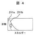
図4は中性子検出器によってガンマ線を検出したときの検出信号(エネルギースペクトル)の一例を示す図である。図4に示したように、ガンマ線源を観測していない時のエネルギースペクトル211aとガンマ線源を観測している時のエネルギースペクトル211bの違いは、ガンマ線の入射に伴うスペクトルの上限エネルギーと全計数である。中性子検出器では、入射するガンマ線量が増加すると中性子検出器のセンサ部で検出する信号の量が増加し、1回の検出を行う間に複数のガンマ線に伴う信号を検出する。このため、1回の検出で検出器に付与されるエネルギーは1回の検出の間に入射した複数のガンマ線が検出器に付与するエネルギーの和となるため、入射するガンマ線が増加すると、ガンマ線に伴うスペクトルの上限エネルギーが大きくなる。従って、ガンマ線に伴うエネルギーの上限レベルが増加することによって、視線上にガンマ線源が存在することがわかる。なお、中性子を観測した際も中性子検出器12での計数の増加は見られるが、この場合はエネルギースペクトル上に中性子検出に伴う特有の構造が現れるため、ガンマ線検出による計数の増加と中性子検出による計数の増加を判別することは可能である。
FIG. 4 is a diagram showing an example of a detection signal (energy spectrum) when gamma rays are detected by a neutron detector. As shown in FIG. 4, the difference between the
上記したように線源200がガンマ線源であった場合、ガンマ線検出器11および中性子検出器12のエネルギースペクトルにガンマ線源に由来する変化が現れる。このため、2種類の検出器の観測方向とエネルギースペクトルから、ガンマ線源の3次元的な位置及び種類を特定することができる。
As described above, when the
次に線源200が中性子源だった場合について説明する。
Next, a case where the
図5はガンマ線検出器によって中性子を検出したときの検出信号(エネルギースペクトル)の一例を示す図である。中性子源を観測していない時のエネルギースペクトル202aと中性子源を観測している時のエネルギースペクトル202bの大きな違いは、エネルギースペクトル202bでは、エネルギースペクトル202aでは見られなかった全吸収ピーク(図5中、矢印の右隣のピーク)が見られることである。
FIG. 5 is a diagram showing an example of a detection signal (energy spectrum) when neutrons are detected by a gamma ray detector. The large difference between the
ガンマ線検出器11で使用されるセンサ物質と中性子が反応すると、2次電子や2次ガンマ線、荷電粒子などが放出される。この2次ガンマ線をガンマ線検出器11で検出することで、ガンマ線検出器のエネルギースペクトル上に上記反応(センサ物質と中性子の反応)に伴う特有の構造が現れる。
When the sensor material used in the
本実施形態では、ガンマ線検出器11の一例としてCdTe半導体検出器を用いた場合について説明する。CdTe半導体検出器を構成するCdには複数の同位体があり、そのうちCd‐113は中性子と中性子捕獲反応を起こし、558keVのエネルギーを持つガンマ線を放出する(出典:Nuclear Physics A Volume 412, Issue 1, 2 January 1984, Pages 113‐140 “The level structure of 114Cd from (n,γ) and (d,p) studies“)。このガンマ線をCdTe半導体検出器自身で検出すると、図5に示したエネルギースペクトル202bのようにエネルギースペクトル上に全吸収ピークが現れる。前述のようにガンマ線のエネルギーは核種ごとに固有であるため、Cd‐113が中性子捕獲反応を起こして発生したガンマ線のエネルギーも固有であり、558keVのガンマ線を検知したことにより、中性子とCd‐113の中性子捕獲反応が起こったと判断することができる。従って、558keVの全吸収ピークを検出することで、前記ガンマ線検出器11に中性子が入射したと判断することができる。
In the present embodiment, a case where a CdTe semiconductor detector is used as an example of the
ここでは、Cd‐113の中性子捕獲反応で放出するガンマ線のエネルギーを558keVとして説明したが、例えば651keVや805keVなど、Cd‐113及び中性子が中性子捕獲反応を起こして放出されるガンマ線が持つエネルギーであれば何でも良い。また、反応する元素はCd‐113ではなく、Cd‐116などのCd同位体でも良く、Te‐130などのTe同位体でもよい。さらに、CdTeではなく、CZTなどの他のセンサ物質でも良い。その際、反応の種類は、中性子捕獲反応以外でも良く、センサで使用されている物質ごとに中性子との反応確率が高く(同位体比及び反応断面積が大きく、励起しやすいもの)、ガンマ線検出器11で検出し易い適切な反応を選択することが好ましい。
Here, the energy of gamma rays emitted by the neutron capture reaction of Cd-113 has been described as 558 keV. Anything is fine. The reacting element is not Cd-113 but may be a Cd isotope such as Cd-116 or a Te isotope such as Te-130. Furthermore, instead of CdTe, other sensor substances such as CZT may be used. At that time, the reaction type may be other than neutron capture reaction, and each substance used in the sensor has a high reaction probability with neutrons (high isotope ratio and reaction cross section, easy to excite), and gamma ray detection It is preferable to select an appropriate reaction that can be easily detected by the
各元素及び中性子の反応で放出されるエネルギーは、例えばNNDC(National Nuclear Data Center)が発表しているENSDF(Evaluated Nuclear Structure Data File)を参照することで得ることができる。上記文献等を参照し、ガンマ線検出器11のセンサ物質を構成する元素と中性子とが反応して放出するエネルギーをあらかじめ把握しておくことで、ガンマ線検出器で中性子由来のピーク(2次ガンマ線の全吸収ピーク)の検出の有無を判断することができる。
The energy released by the reaction of each element and neutron can be obtained, for example, by referring to an ENSDF (Evaluated Nucleus Structure Data File) published by NNDC (National Nuclear Data Center). By referring to the above-mentioned documents and the like and grasping in advance the energy emitted by the reaction of the elements constituting the sensor substance of the
図6は中性子検出器によって中性子を検出したときの検出信号(エネルギースペクトル)の一例を示す図である。図6は、線源200が中性子源である時に中性子検出器12で得られるエネルギースペクトルの一例である。中性子源を観測していない時のエネルギースペクトル212aと中性子源を観測している時のエネルギースペクトル212bの違いは、前記エネルギースペクトル212bでは、前記エネルギースペクトル212aでは観測されないエネルギー範囲に計数(図6中、矢印の左隣のピーク)が現れることである。このように中性子検出器12では、中性子の検出に伴い、ガンマ線計測時とは異なる構造がエネルギースペクトル上に現れる。
FIG. 6 is a diagram illustrating an example of a detection signal (energy spectrum) when neutrons are detected by a neutron detector. FIG. 6 is an example of an energy spectrum obtained by the
本実施形態では、中性子検出器12の一例として、BF3検出器を用いた場合について説明する。BF3検出器はBF3(三フッ化ホウ素)ガスを封入した検出器である。前記BF3ガスを構成するホウ素の同位体であるB‐10は熱中性子との反応確率が高く、中性子と反応してα粒子を放出する。α粒子はガスを電離し、電子イオン対を生成する。この電子イオン対が検出器で検知され、電気信号として検出される。α粒子がガス中を透過することによって発生する電子イオン対の数はα粒子がガス中を透過する際に失ったエネルギーに依存する。従って、電気信号の大きさはα粒子が検出器に付与したエネルギーに相当する。また、α粒子の飛程は短いので、多くの場合α粒子の全エネルギーが検出器中に付与される。従って、BF3検出器から得られるエネルギースペクトルでは、α粒子のエネルギーに相当するエネルギー領域にピークが現れる。これは、ガンマ線を検出器した時に見られる連続スペクトルとは異なるため、中性子由来のピークとガンマ線由来の最大エネルギー及び全計数の増加をエネルギースペクトル上で判別することができる。
In the present embodiment, a case where a BF 3 detector is used as an example of the
ここでは、中性子検出器をBF3検出器としたが、B‐10検出器やHe‐3検出器などの中性子検出器であっても同様に、中性子検出に伴ったエネルギースペクトル上の構造により中性子検出を判断することができる。 Here, the neutron detector is a BF 3 detector. However, neutron detectors such as a B-10 detector and a He-3 detector also have a neutron detector due to the structure on the energy spectrum accompanying neutron detection. Detection can be determined.
以上説明したように、ガンマ線検出器11及び中性子検出器12共に線源200の種類ごとに検出されるエネルギースペクトルの形状が異なり、それぞれの検出器がガンマ線及び中性子の両方を検出可能なため、線源200がガンマ線源であっても中性子源であっても、2つの検出器の観測方向からガンマ線又は中性子を検出し、ガンマ線又は中性子の3次元的な位置を特定することができる。また、線源200がガンマ線源である場合には、ガンマ線検出器11で得られるエネルギースペクトルを分析することで、核種の特定を行うことができる。
As described above, both the
したがって、本発明の放射線計測装置によれば、1つの装置で(ガンマ線用、中性子用と異なる装置を使用することなく)任意の方向からの複数種類の放射線を検出し、得られた検出信号から複数の放射線源の3次元的な位置及び種類を特定することが可能であるため、線源の3次元的な位置及び種類の特定にかかる作業時間を大幅に短縮化することが可能となる。したがって、作業者が被ばくするおそれを大幅に低減することができる。 Therefore, according to the radiation measurement apparatus of the present invention, a single apparatus detects a plurality of types of radiation from any direction (without using an apparatus different from that for gamma rays and neutrons), and from the obtained detection signal Since it is possible to specify the three-dimensional positions and types of a plurality of radiation sources, it is possible to greatly shorten the work time required to specify the three-dimensional positions and types of the radiation sources. Therefore, the risk of exposure by the operator can be greatly reduced.
図1においては、データ処理装置28が放射線検出器11,12と接続された態様を示しているが、データ処理装置28は放射線検出器(放射線検出部)とは別に設けられていてもよい。例えば、図1に示したように、放射線検出器11,12に記憶装置29a,29bを設け、放射線検出器11,12で測定した放射線信号及び観測方向に関するデータを記憶しておき、該データをデータ媒体を介して放射線検出器11,12とは別に設けられたデータ処理装置に移動して、線源の3次元的な位置及び核種の特定を行うような構成としてもよい。
Although FIG. 1 shows a mode in which the
上述した実施形態では放射線計測装置に2台の放射線検出器(ガンマ線検出器11及び中性子検出器)を搭載する場合について説明したが、線源の3次元的な位置の特定を行うことができる構成を有していれば、放射線検出器は何台搭載されていてもよい。また、同種類の放射線検出器を複数台備えていてもよい。例えば、ガンマ線源の種類(核種)を特定する必要が無く、ガンマ線源の3次元的な位置の特定及び中性子源の3次元的な位置の特定を行う場合には、中性子検出器2台を備えたものであってもよく、またガンマ線検出器2台を備えて、ガンマ線源の3次元的な位置及び種類の特定及び中性子源の3次元的な位置の特定を行うようにしてもよい。
In the above-described embodiment, the case where two radiation detectors (
放射線検出部旋回駆動部21a,21b、遮蔽体101a,101b及び放射線入射部102a,102bとしては特に限定は無く、公知の技術を用いることができる。例えば、放射線検出部旋回駆動部21a,21bとして電動アクチュエータを用いることができる。また、放射線検出部旋回駆動部は自動で駆動されるものに限定されず、手動で駆動されるものであってもよい。遮蔽体101a,101bとしては、鉛を好ましく用いることができる。放射線入射部102a,102bとしてはコリメータを用いることができる。また、指向性を有する放射線検出部20a,20bとしては、図1のように放射線検出器11,12と遮蔽体101a,101bと放射線入射部102a,102bとで構成されるものでもよいし、遮蔽体101a,101bとコンプトンカメラとで構成されるものであってもよい。
There is no particular limitation on the radiation detection unit turning
<第2の実施形態>
本発明に係る放射線計測装置の第2の実施形態を、図7を用いて説明する。図7は本発明の第2の実施形態における放射線検出部の構成の断面を示す模式図である。
本実施形態では、主に遮蔽体について説明する。遮蔽体以外の構成については、第一の実施形態と同様である。
<Second Embodiment>
A second embodiment of the radiation measuring apparatus according to the present invention will be described with reference to FIG. FIG. 7 is a schematic diagram showing a cross section of the configuration of the radiation detection unit according to the second embodiment of the present invention.
In the present embodiment, the shielding body will be mainly described. The configuration other than the shield is the same as in the first embodiment.
図7において、放射線検出部30は、指向性を有するように、放射線検出器10(ガンマ線検出器又は中性子検出器)の検出面110以外がガンマ線遮蔽体103、中性子吸収材104及び中性子減速材(以下、減速材とも称する)105に覆われ、検出面110の前面にコリメータ102を備えている。
In FIG. 7, the
上述した第1の実施形態のように、ガンマ線及び中性子の両方を検出できる構成とする場合では、ガンマ線検出器11および中性子検出器12がガンマ線と中性子の両方に対して指向性を有する必要がある。言い換えると、ガンマ線検出器11及び中性子検出器12の検出器の検出面以外は、ガンマ線と中性子の両方に対して遮蔽能力を有する必要がある。従って、鉛などのガンマ線遮蔽体103のみでは、中性子に対する遮蔽能力が十分ではない場合もある。このため、ガンマ線遮蔽体103の周囲に中性子吸収材104および中性子減速材105を設置し、中性子に対しても遮蔽能力を有する構造とすることが好ましい。
In the case of a configuration capable of detecting both gamma rays and neutrons as in the first embodiment described above, the
中性子が放射線検出器10に向けて照射されている時、本実施形態の構造によれば、高速中性子を中性子減速材105が減速させて熱中性子とし、中性子吸収材104が該熱中性子を吸収する。熱中性子と中性子吸収材104の反応によって放出される2次粒子は、ガンマ線遮蔽体103によって吸収されるため、遮蔽体を通る中性子が放射線検出器10に影響を及ぼすことを防ぐことができる。
When neutrons are irradiated toward the
中性子減速材105としては、特に限定は無いが、ポリエチレン又はポリプロピレンが好適である。また、中性子吸収材104としては、B4CやGd2O3が好適である。
The
本実施形態の構成によって、ガンマ線および中性子の両方に対して十分な遮蔽能力を有する遮蔽体を提供することができる。 With the configuration of the present embodiment, it is possible to provide a shield that has a sufficient shielding ability against both gamma rays and neutrons.
なお、放射線を観測する環境が、中性子が減速される環境(例えば、水中)であれば、中性子減速材105を省略してもよい。
Note that the
<第3の実施形態>
本発明に係る放射線計測装置の第3の実施形態を、図8及び9を用いて説明する。図8は本発明の第3の実施形態における放射線計測装置の構成の一部を模式的に示す図であり、図9は本発明の第3の実施形態における放射線計測装置の構成を模式的に示す図である。
<Third Embodiment>
A third embodiment of the radiation measuring apparatus according to the present invention will be described with reference to FIGS. FIG. 8 is a diagram schematically showing a part of the configuration of the radiation measuring apparatus according to the third embodiment of the present invention, and FIG. 9 is a schematic diagram showing the configuration of the radiation measuring apparatus according to the third embodiment of the present invention. FIG.
図8において、ガンマ線検出器11は、放射線を検出する検出面110a以外が遮蔽体101aで覆われ、指向性を有するように検出面110aの前面に放射線入射部102aを備えている。同様に中性子検出器12は放射線を検出する検出面110b以外が遮蔽体101bで覆われ、指向性を有するように検出面110bの前面に放射線入射部102bを備えている。また、第1の光学カメラ13は観測領域Cを観測しており、放射線検出器の視野内に線源200が存在し、ガンマ線検出器11と中性子検出器12による探査により、線源の位置と種類を特定した状況である。
In FIG. 8, the
図9は本発明の第3の実施形態における放射線計測装置の構成を模式的に示す図である。本実施形態が第1の実施形態と異なる点は、第1の光学カメラ13、旋回角演算部25及び制御部26が具備されていることである。従って、本実施形態においては、これらの構成について説明する。その他の構成については、第1の実施形態又は第2の実施形態と同様である。
FIG. 9 is a diagram schematically showing the configuration of a radiation measuring apparatus according to the third embodiment of the present invention. The present embodiment is different from the first embodiment in that a first
図9において、ガンマ線検出器11は旋回駆動部21aによって、中性子検出器12は旋回駆動部21bによって、観測方向を決めることができる。ガンマ線検出器11で得られた検出信号は、データ処理装置28´内の波高分析部22aによって、中性子検出器12で得られた検出信号は、データ処理装置28´内の波高分析部22bによって波高分析され、それぞれのエネルギースペクトルが得られる。得られたエネルギースペクトルを元に線源分析部23によって線源の有無及び線源の種類が特定される。特定された結果は、第1の光学カメラ13によって得られた光学画像と共に表示部24で表示される。作業者は表示部24を見ながら観測領域を指示することができる。旋回角演算部25は、放射線検出器の観測方向と放射線検出器から観測領域への方向とがなす角度を算出し、制御部26に旋回角を伝達する。制御部26は伝達された角度だけ旋回駆動部21a及び21bを旋回させる。
In FIG. 9, the
前述したように、放射線源の探査において線源の種類および場所が不明な環境で実施されることがある。その際、観測対象とする空間の情報が無いことも想定される。例えば、本発明に係る放射線計測装置を移動メカに搭載して使用する場合などは、使用する時々によって観測する対象(線源や構造物)が変わる。 As described above, the radiation source search may be performed in an environment where the type and location of the radiation source are unknown. At that time, it is assumed that there is no information about the space to be observed. For example, when the radiation measuring apparatus according to the present invention is mounted on a moving mechanism and used, an observation target (a radiation source or a structure) changes depending on when it is used.
第1の光学カメラ13により得られた光学画像により、作業者は観測対象を周囲の環境と共に可視化して認識することが可能である。さらに図8のように線源200の位置を特定することができた場合には、観測対象のどの位置に線源200が存在するかを作業者が認識することができる。
From the optical image obtained by the first
本実施形態のように第1の光学カメラ13によって得られた画像を元に作業者が探査位置を指示することで、不必要な探査を実施する必要がなくなり、作業効率が向上する。その際、作業者が指定した観測領域をガンマ線検出器11および中性子検出器12が観測する必要がある。
As in this embodiment, the operator designates the search position based on the image obtained by the first
そこで、表示部24によって映し出された光学画像を元に、観測者が観測対象を認識し、観測対象中の探査する場所(観測領域)を指示する。指示された観測領域を検出器が観測するように旋回角演算部25が旋回角を算出し、該算出結果を元に、制御部26が旋回駆動部21a及び旋回駆動部21bを駆動させるため、作業者の指示に従って、観測領域を決めることができる。
Therefore, based on the optical image displayed by the
以上説明したように、第1の光学カメラ13、旋回角演算部25及び制御部26の機能により、観測対象が不明な環境においても、効率的に作業を実施することができる。
As described above, the functions of the first
<第4の実施形態>
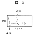
本発明の放射線計測装置の第4の実施形態を、図10を用いて説明する。図10は本発明の第4の実施形態において中性子検出器によって中性子を検出したときの検出信号(エネルギースペクトル)の一例を示す図である。図10は第1の実施形態において、BF3検出器ではなく、有機シンチレータを用いて中性子を観測した場合に中性子検出器から得られるエネルギースペクトルの一例である。
<Fourth Embodiment>
A fourth embodiment of the radiation measuring apparatus of the present invention will be described with reference to FIG. FIG. 10 is a diagram showing an example of a detection signal (energy spectrum) when neutrons are detected by the neutron detector in the fourth embodiment of the present invention. FIG. 10 is an example of an energy spectrum obtained from a neutron detector when neutrons are observed using an organic scintillator instead of a BF 3 detector in the first embodiment.
本実施例では、中性子検出器12について説明する。その他の機能および構造については、他の実施例と同様である。
In this embodiment, the
第1の実施形態において、中性子検出器12をB‐10検出器、BF3検出器又はHe‐3検出器に代表される熱中性子検出器として説明した。しかし、中性子源が高速中性子であることが想定される場合もある。そのような場合、中性子検出器12としては、高速中性子の検出に優れた有機シンチレータを用いることができる。
In the first embodiment, the
中性子源を観測していない時のエネルギースペクトル221aと中性子源を観測している時のエネルギースペクトル221bの違いは、エネルギースペクトル221bでは、エネルギースペクトル221aとは異なるエネルギー範囲に計数(図10中、矢印の左隣のピーク)が存在していることである。
The difference between the
有機シンチレータは発光減衰時間が短いため、高計数率環境においても、複数の信号が重なる現象が起こり難い。従って、観測範囲にガンマ線源を観測した時、BF3のように、エネルギースペクトル上でガンマ線に基づく連続スペクトルの上限エネルギーが上昇する現象が見られない可能性がある。しかし、ガンマ線源より放出されたガンマ線の計数率が増加するため、図10のエネルギースペクトル221aの計数が増加する。
Since the organic scintillator has a short emission decay time, it is difficult for a plurality of signals to overlap even in a high count rate environment. Therefore, when a gamma ray source is observed in the observation range, there is a possibility that a phenomenon in which the upper limit energy of the continuous spectrum based on gamma rays rises on the energy spectrum, such as BF 3 , may not be seen. However, since the count rate of gamma rays emitted from the gamma ray source increases, the count of the
従って、有機シンチレータにより、中性子源を観測した場合は、エネルギースペクトルに構造の変化が見られるため中性子源を観測していると判断でき、ガンマ線源を観測した場合は、構造の変化が見られなかったとしても、低エネルギーの計数の増加が起こるため、ガンマ線源を観測していると判断することができる。 Therefore, when a neutron source is observed with an organic scintillator, it can be judged that the neutron source is observed because a structural change is seen in the energy spectrum. When a gamma ray source is observed, no structural change is observed. Even so, it can be determined that the gamma ray source is being observed because the low energy count increases.
以上より、ガンマ線検出器11と高速中性子を検出可能な中性子検出器12として有機シンチレータを用いることにより、線源の種類と位置を特定することができる。
As described above, the type and position of the radiation source can be specified by using the organic scintillator as the
<第5の実施形態>
本発明の放射線計測装置の第5の実施形態を、図11及び図12を用いて説明する。図11は本発明の第5の実施形態における放射線検出部の構成の断面を模式的に示す図であり、図12は本発明の第5の実施形態においてガンマ線検出器によって中性子を検出したときの検出信号(エネルギースペクトル)の一例を示す図である。
<Fifth Embodiment>
A fifth embodiment of the radiation measuring apparatus of the present invention will be described with reference to FIGS. FIG. 11 is a diagram schematically showing a cross section of the configuration of the radiation detection unit in the fifth embodiment of the present invention, and FIG. 12 is a diagram when neutrons are detected by the gamma ray detector in the fifth embodiment of the present invention. It is a figure which shows an example of a detection signal (energy spectrum).
本実施形態では、放射線検出部40の構成について説明する。その他の機能および構造については、他の実施形態と同様である。
In the present embodiment, the configuration of the
図11において、放射線検出部40は、指向性を有するように、ガンマ線検出器11の検出面110a以外が遮蔽体101aに覆われ、検出面110aの前面に放射線入射部102aを備え、さらに検出面110aの前面と放射線入射部102aとの間にコンバータ物質111を具備している。
In FIG. 11, a
ここでは、ガンマ線検出器11としてCdTe半導体検出器、コンバータ物質111としてGdを用いた場合について説明する。なお、ガンマ線検出器11はCdTeに限られるものではなく、コンバータ111は、中性子と反応して2次粒子を放出する物質であればよく、Gdに限られるものではない。
Here, a case where a CdTe semiconductor detector is used as the
第1の実施形態で述べたように、CdTe半導体検出器で中性子を検出する場合、CdTeを構成する同位体と中性子の反応によって放出されるガンマ線を再びCdTe半導体検出器で検出する必要がある。 As described in the first embodiment, when neutron is detected by the CdTe semiconductor detector, it is necessary to detect again by the CdTe semiconductor detector the gamma rays emitted by the reaction between the isotopes constituting CdTe and the neutrons.
ガンマ線はエネルギーが高いほど物質を透過する能力が高いため、上記過程によって発生したガンマ線は低エネルギーであるほど、検出は容易である(短時間で済む)。言い換えれば、2次ガンマ線のエネルギーが高いとエネルギースペクトル上でピークを形成するために長い計測時間が必要である。 The higher the energy, the higher the ability of the gamma ray to pass through the substance. Therefore, the lower the energy of the gamma ray generated by the above process, the easier the detection (a shorter time is required). In other words, when the secondary gamma ray energy is high, a long measurement time is required to form a peak on the energy spectrum.
Gdは中性子捕獲反応によって、80keV又は181keV等の比較的低エネルギーのガンマ線を放出する。従って、Gdと中性子の反応によって発生したガンマ線をCdTe半導体検出器で検出することは、CdTeと中性子の反応によって発生したガンマ線よりも検出し易い場合がある。 Gd emits relatively low energy gamma rays such as 80 keV or 181 keV by a neutron capture reaction. Therefore, it may be easier to detect gamma rays generated by the reaction between Gd and neutrons with a CdTe semiconductor detector than gamma rays generated by the reaction between CdTe and neutrons.
図12に示したように、中性子源を観測していない時のエネルギースペクトル231aと中性子源を観測している時のエネルギースペクトル231bの違いは、エネルギースペクトル231bでは、エネルギースペクトル231aでは見られないピーク(図10中、矢印の右隣のピーク)が存在することである。
As shown in FIG. 12, the difference between the
本実施形態で検出するピークは低エネルギーであるため、周囲からより高いガンマ線が入射する場合、エネルギーの高いガンマ線の検出に基づくコンプトン散乱成分にGdと中性子の核反応由来のガンマ線のピークが重なり、図12のエネルギースペクトル231bのようなスペクトルとなる。 Since the peak detected in this embodiment is low energy, when higher gamma rays are incident from the surroundings, the peak of gamma rays derived from the nuclear reaction between Gd and neutrons overlaps with the Compton scattering component based on detection of high energy gamma rays, It becomes a spectrum like the energy spectrum 231b of FIG.
しかしながら、中性子とコンバータ物質の反応によって、コンバータ物質の種類ごとに固有のエネルギーを持ったガンマ線が放出されるため、着目するエネルギー範囲にコンバータ物質111由来の固有のエネルギーのピークが見られるのであれば、中性子を検出したと判断することができる。
However, the reaction between the neutron and the converter material emits gamma rays having a specific energy for each type of converter material, so that a peak of the specific energy derived from the
<第6の実施形態>
本発明の放射線計測装置の第6の実施形態を、図13及び図14を用いて説明する。図13及び14は本発明の第6の実施形態における放射線検出部の一例を模式的に示す図である。
<Sixth Embodiment>
A sixth embodiment of the radiation measuring apparatus of the present invention will be described with reference to FIGS. 13 and 14 are diagrams schematically illustrating an example of a radiation detection unit according to the sixth embodiment of the present invention.
図13において、放射線検出部50aは、ガンマ線検出器11の放射線を検出する検出面110a以外が遮蔽体101aによって覆われ、指向性を有するように検出面110aの前面に放射線入射部102aを備える構造である。また、検出面110aの前面と放射線入射部102aとの間には、コンバータ物質111が具備されており、さらにコンバータ物質111と放射線入射部102aとの間には中性子減速材121aが具備されている。
In FIG. 13, the
図14において、放射線検出部50bは、中性子検出器12の放射線を検出する検出面110b以外が遮蔽体101bによって覆われ、指向性を有するように検出面110bの前面に放射線入射部102bを備える構造である。検出面110bと放射線入射部102bとの間には中性子減速材121bが具備されている。
In FIG. 14, the
本実施形態の特徴は、減速材121a,121bを設けたことにある。これらの構成以外は他の実施形態と同様であり、コンバータ物質111は省略してもよい。
The feature of this embodiment is that
減速材121a,121bは中性子と反応して、中性子の速度を減速させ、熱化させる。従って、本実施形態では、環境中に存在する中性子が熱外又は高速中性子であったとしても、ガンマ線検出器11、中性子検出器12あるいはコンバータ物質111には、熱中性子が入射する構造である。
The
本実施形態により、例えば、観測範囲中の線源200とガンマ線検出器11又は中性子検出器12の間に減速作用を及ぼす物質が無く、線源200が熱外又は高速中性子源であったとしても、ガンマ線検出器11および中性子検出器12において熱中性子を検出することができる。
According to the present embodiment, for example, even if there is no substance that exerts a decelerating action between the
中性子減速材121a,121bとしては水、ポリエチレンなどの物質が好ましく、これらはガンマ線に対する遮蔽能力は小さい。従って、ガンマ線検出器11の検出面110aの前面に減速材121aがあったとしてもガンマ線検出に対する影響は小さく、同様に、中性子検出器12の検出面110bの前面に減速材121bがあったとしても、ガンマ線検出に対する影響は小さい。
As the
本実施形態で示した構成を用いると、中性子に対する減速作用の少ない環境中においても線源の種類及び位置を特定することができる。 When the configuration shown in the present embodiment is used, the type and position of the radiation source can be specified even in an environment where there is little decelerating action against neutrons.
<第7の実施形態>
本発明の放射線計測装置の第7の実施形態を、図15を用いて説明する。図15は本発明の第7の実施形態における表示部の表示画面の一例を模式的に示す図である。
<Seventh Embodiment>
A seventh embodiment of the radiation measuring apparatus of the present invention will be described with reference to FIG. FIG. 15 is a diagram schematically showing an example of a display screen of the display unit in the seventh embodiment of the present invention.
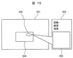
図15は、第3の実施形態(図9)において、観測エリア表示画面301中に、構造物304が存在し、第1の光学カメラ13(図示せず)から構造物304へ向けた視線の延長上に線源200(図示せず)が存在している状況である。
FIG. 15 shows the
本実施例では、表示画面について説明する。表示画面以外の構成については、上記した第3の実施形態と同様である。 In this embodiment, a display screen will be described. The configuration other than the display screen is the same as in the third embodiment described above.
線源探査により線源が見つかると、観測エリア表示画面301上に線源表示305が示される。線源表示305は構造物304と重なって表示されるが、放射線源位置測定部27によって得られた奥行き方向の情報がデータ表示画面302に距離として表示される。データ表示画面302には、例えば第1の光学カメラ13からの距離、線源の種類及び線源の強度が表示される。また、ガンマ線検出器11で得られたエネルギースペクトルおよび中性子検出器12で得られたエネルギースペクトルがスペクトル表示画面303に表示される。
When a source is found by the source search, a
データ表示画面302に示された距離の情報と、例えばレーザー距離計などで得られた構造物との距離の情報から、線源表示305が構造物304の表面なのか、内部なのか、背面なのか、背後なのかという情報を得ることができる。
From the information on the distance shown on the
従って、本実施形態によれば、第1の光学カメラ13で取得した2次元画像を用いて、3次元の核種分布の情報を提供することができる。
Therefore, according to the present embodiment, it is possible to provide information on the three-dimensional nuclide distribution using the two-dimensional image acquired by the first
<第8の実施形態>
本発明の放射線計測装置の第8の実施形態を、図16を用いて説明する。図16は本発明の第8の実施形態における放射線計測装置の構成を模式的に示す図である。
<Eighth Embodiment>
An eighth embodiment of the radiation measuring apparatus of the present invention will be described with reference to FIG. FIG. 16 is a diagram schematically showing the configuration of a radiation measuring apparatus according to the eighth embodiment of the present invention.
本実施形態と第1の実施形態及び第3の実施形態との違いは、第1の光学カメラ13の他に、第2の光学カメラ14と、3次元形状構成部31を有することである。
The difference between the present embodiment and the first and third embodiments is that, in addition to the first
図16に示したように、本実施形態の放射線計測装置100´´は、第1の光学カメラ13に加えて第2の光学カメラ14を備えることで、観測対象エリアの光学画像を2方向から得る。2方向から取得した光学画像に基づいて、3次元形状構成部31により、観測対象エリア中の構造物の3次元形状を構成することができる。
As shown in FIG. 16, the
このような装置構成とすることで、線源の位置だけでなく、観測対象エリアの情報も3次元として得ることができるため、3次元の構造物の形状情報に3次元の線源位置情報を対応させて記録することが可能となる。 By adopting such an apparatus configuration, not only the position of the radiation source but also information on the observation target area can be obtained in three dimensions. Therefore, the three-dimensional source position information is added to the shape information of the three-dimensional structure. It is possible to record correspondingly.
<第9の実施形態>
本発明の放射線計測装置の第9の実施形態を、図17を用いて説明する。図17は本発明の第9の実施形態における表示部の表示画面の一例を模式的に示す図である。
<Ninth Embodiment>
A ninth embodiment of the radiation measuring apparatus of the present invention will be described with reference to FIG. FIG. 17 is a diagram schematically showing an example of the display screen of the display unit in the ninth embodiment of the present invention.
観測エリアの3次元情報を元に線源200の位置を示す方法として、3次元の構造物の図を表示する方法がある。この時、3次元情報を得る方法は、第8の実施形態で示した方法でも良いし、CADなどのデータをあらかじめデータベースとして装置内に保持し、読みだす機能を有していても良い。
As a method of indicating the position of the
図17は、観測エリア中に存在するある構造物401上に線源200(図示せず)があった時に、表示部24(図示せず)により出力される線源位置表示の一例である。表示画面411では、構造物401は3次元の図として表示され、その構造物401上に線源表示402aが構造物401の表示上の前面以外の場所に示されている。本実施形態の表示部24は、画面上に表示された構造物や視線を回転させる機能を有しており、表示画面411の視線を回転させ、表示画面412が得られる。表示画面412では、線源表示402bが構造物401の表示上の前面に現れている。
FIG. 17 is an example of the radiation source position display output by the display unit 24 (not shown) when the radiation source 200 (not shown) is on a
本実施形態によれば、ガンマ線検出器11と中性子検出器12によって特定した線源200(図示せず)の3次元空間上の位置を表示することができる。
According to this embodiment, the position in the three-dimensional space of the radiation source 200 (not shown) specified by the
<第10の実施形態>
本発明の放射線計測装置の第10の実施形態を、図18を用いて説明する。図18は本発明の第10の実施形態における放射線検出部の構成の断面を模式的に示す図である。
<Tenth Embodiment>
A tenth embodiment of the radiation measuring apparatus of the present invention will be described with reference to FIG. FIG. 18 is a diagram schematically showing a cross section of the configuration of the radiation detection unit according to the tenth embodiment of the present invention.
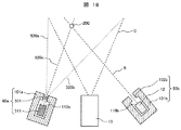
図18において、アレイ型ガンマ線検出器511は、遮蔽体101aで覆われ、アレイ型ガンマ線検出器511が画素ごとに指向性を有するように放射線入射部にピンホールコリメータ501を備えている。同様に中性子検出器12は遮蔽体101bで覆われ、指向性を有するように周囲の1方向にコリメータ102bを備えている。また、光学カメラ13は観測領域Cを観測しており、視野内に線源200が存在し、アレイ型ガンマ線検出器11と中性子検出器12による探査により、線源の位置と種類を特定した状況である。
In FIG. 18, an array type
図17では、アレイ型ガンマ線検出器11のいずれかの画素が観測する範囲は視線520aから視線520bの間であり、そのうち一つの画素の視線520cが線源200を観測している。画素は紙面に対して垂直な方向にも複数あり、紙面に平行な方向、垂直な方向のいずれに対しても画素数に制限はない。
In FIG. 17, the range observed by any pixel of the array-type
本実施例の構成では、光学カメラの観測範囲とアレイ型ガンマ線検出器511の観測範囲がほぼ一致しているため、アレイ型ガンマ線検出器511を旋回させる必要はない。従って、旋回駆動部は中性子検出器12用のものだけで良い。
In the configuration of the present embodiment, since the observation range of the optical camera and the observation range of the array type
このため、アレイ型ガンマ線検出器511で線源方向が特定された後、中性子検出器12を、線源が存在する視線上を順次観測することで、線源の位置の特定に係る作業時間を短縮することができる。
For this reason, after the source direction is specified by the array-type
本実施形態では、ガンマ線検出器を複数画素で構成される検出器としたが、中性子検出器を複数画素で構成される検出器としても良く、両検出器を複数画素で構成した場合は、検出器の駆動機構が無くても良い。また、複数画素で構成される検出器を用いた場合であっても、駆動機構を有していても良い。
<第11の実施形態>
本発明の放射線計測装置の第11の実施形態を説明する。
In this embodiment, the gamma ray detector is a detector composed of a plurality of pixels. However, the neutron detector may be a detector composed of a plurality of pixels, and when both detectors are composed of a plurality of pixels, detection is performed. There is no need to provide a driving mechanism for the container. Further, even when a detector composed of a plurality of pixels is used, a driving mechanism may be provided.
<Eleventh embodiment>
An eleventh embodiment of the radiation measuring apparatus of the present invention will be described.
本発明の放射線計測装置の検出器として、ガンマ線検出器11と中性子検出器12を用いた。しかし、既に説明したように、ガンマ線検出器11はガンマ線と中性子を検出する機能を有している。従って、中性子検出器12の代わりにガンマ線検出器11を用いたとしても、中性子源とガンマ線源の特定は可能である。
A
以上、説明したように、本発明に係る放射線計測装置によれば、1つの装置で任意の方向からの複数種類の放射線を検出し、得られた検出信号から複数の放射線源の3次元的な位置及び種類を特定することが可能な放射線計測装置を提供することができることが示された。 As described above, according to the radiation measuring apparatus according to the present invention, a single apparatus detects a plurality of types of radiation from an arbitrary direction, and a three-dimensional view of a plurality of radiation sources is obtained from the obtained detection signals. It has been shown that a radiation measuring apparatus capable of specifying the position and type can be provided.
なお、上述した実施形態や実施例は、本発明の理解を助けるために説明したものであり、本発明は、記載した具体的な構成のみに限定されるものではない。例えば、ある実施例の構成の一部を他の実施例の構成に置き換えることが可能であり、また、ある実施例の構成に他の実施例の構成を加えることも可能である。すなわち、本発明は、本明細書の実施形態や実施例の構成の一部について、削除・他の構成に置換・他の構成の追加をすることが可能である。 The above-described embodiments and examples have been described for the purpose of facilitating understanding of the present invention, and the present invention is not limited to the specific configurations described. For example, a part of the configuration of one embodiment can be replaced with the configuration of another embodiment, and the configuration of another embodiment can be added to the configuration of one embodiment. That is, according to the present invention, a part of the configurations of the embodiments and examples of the present specification can be deleted, replaced with other configurations, and added with other configurations.
10…放射線検出器、11…ガンマ線検出器、12…中性子検出器、13…第1の光学カメラ、14…第2の光学カメラ、20a,20b,30,40,50a,50b,60a,60b…放射線検出部、21a,21b…放射線検出器旋回駆動部、22a,22b…波高分析部、23…線源分析部、24…表示部、25…旋回角演算部、26…制御部、27…放射線源位置測定部、28,28´,28´´…データ処理装置、29a,29b…記憶装置、31…3次元形状構成部、100,100´,100´´…放射線計測装置、101a,101b…放射線遮蔽体、102,102a,102b…放射線入射部、103…ガンマ線遮蔽体、104…中性子吸収材、105…中性子減速材、110,110a,110b…放射線検出面、111…コンバータ物質、121a,121b…減速材、200…放射線源、201a…ガンマ線検出器におけるガンマ線源非観測時のエネルギースペクトル、201b…ガンマ線検出器におけるガンマ線源観測時のエネルギースペクトル、202a,231a…ガンマ線検出器における中性子非観測時のエネルギースペクトル、202b,231b…ガンマ線検出器における中性子観測時のエネルギースペクトル、212a,221a中性子検出器における中性子非観測時のエネルギースペクトル、212b,221b…中性子検出器における中性子観測時のエネルギースペクトル、211a…中性子検出器におけるガンマ線非観測時のエネルギースペクトル、211b…中性子検出器におけるガンマ線観測時のエネルギースペクトル、301,411,412…観測エリア表示画面、302…データ表示画面、303…スペクトル表示画面、304,401…構造物、305,402a,402b…線源表示、501…ピンホールコリメータ、511…アレイ型ガンマ線検出器、520a,520b,520c…アレイ型ガンマ線検出器の画素の視線、A…ガンマ線検出器観測方向、B…中性子検出器観測方向、C…光学カメラ観測領域。
DESCRIPTION OF
Claims (20)
前記放射線検出部がそれぞれ任意の方向からの放射線を観測できるように、前記複数の放射線検出部を互いに異なる位置から互いに独立して旋回可能とした放射線検出部旋回駆動部と、
前記放射線検出部で得られた放射線の検出信号を処理するためのデータ処理装置とを備え、
前記放射線検出部は、ガンマ線又は中性子を検出して検出信号を生成し、
前記データ処理装置は、前記放射線検出部の観測方向と前記ガンマ線及び中性子の検出信号とから放射線源の3次元的な位置及び種類を特定することを特徴とする放射線計測装置。 A plurality of radiation detectors having directivity;
A radiation detection unit swivel drive unit that allows the plurality of radiation detection units to pivot independently from different positions so that the radiation detection unit can observe radiation from any direction, and
A data processing device for processing a radiation detection signal obtained by the radiation detection unit,
The radiation detection unit generates a detection signal by detecting gamma rays or neutrons,
The data processing apparatus is characterized in that the three-dimensional position and type of a radiation source are specified from an observation direction of the radiation detection unit and detection signals of the gamma rays and neutrons.
前記放射線検出器としてガンマ線検出器及び中性子検出器を含み、
前記データ処理装置は、前記ガンマ線検出器で得られたガンマ線の検出信号からガンマ線のエネルギースペクトルを算出し、前記中性子検出器で得られた中性子の検出信号から中性子のエネルギースペクトルを算出し、
前記ガンマ線のエネルギースペクトル中に現れる前記ガンマ線由来の全吸収ピークと前記中性子のエネルギースペクトルの最大エネルギー及び全計数とに基づいてガンマ線源の3次元的な位置を特定し、
前記ガンマ線のエネルギースペクトル中に現れる前記ガンマ線由来の全吸収ピークに基づいて前記ガンマ線源の核種を特定し、
前記ガンマ線のエネルギースペクトル中に現れる前記中性子由来の全吸収ピークと前記中性子のエネルギースペクトル中に現れる前記中性子由来のピークとに基づいて中性子源の3次元的な位置を特定することを特徴とする請求項1に記載の放射線計測装置。 The radiation detection unit includes a radiation detector,
Including a gamma ray detector and a neutron detector as the radiation detector,
The data processing device calculates a gamma ray energy spectrum from a gamma ray detection signal obtained by the gamma ray detector, calculates a neutron energy spectrum from a neutron detection signal obtained by the neutron detector,
Determining the three-dimensional position of the gamma ray source based on the total absorption peak derived from the gamma ray appearing in the energy spectrum of the gamma ray and the maximum energy and the total count of the energy spectrum of the neutron,
Identifying the nuclide of the gamma ray source based on the total absorption peak derived from the gamma ray appearing in the energy spectrum of the gamma ray;
The three-dimensional position of the neutron source is specified based on the total absorption peak derived from the neutron appearing in the energy spectrum of the gamma ray and the peak derived from the neutron appearing in the energy spectrum of the neutron. Item 2. The radiation measuring apparatus according to Item 1.
前記放射線検出器は、放射線と反応するセンサ物質を含む放射線検出面を有し、
前記放射線検出部に指向性を持たせるために、前記放射線検出器の前記放射線検出面以外を覆う放射線遮蔽体と、前記放射線検出面の前面に設けられた放射線入射部とを備えることを特徴とする請求項1乃至3のいずれか1項に記載の放射線計測装置。 The radiation detection unit includes a radiation detector,
The radiation detector has a radiation detection surface containing a sensor material that reacts with radiation,
In order to give directivity to the radiation detection unit, the radiation detection unit includes a radiation shield that covers the radiation detector other than the radiation detection surface, and a radiation incident unit provided in front of the radiation detection surface. The radiation measuring apparatus according to any one of claims 1 to 3.
前記放射線検出器としてガンマ線検出器を含み、
前記ガンマ線検出器の前記放射線検出面の前面と前記放射線入射部との間に、前記中性子と反応を起こすコンバータ物質を備えることを特徴とする請求項4に記載の放射線計測装置。 The radiation detection unit includes a radiation detector,
Including a gamma ray detector as the radiation detector,
The radiation measurement apparatus according to claim 4, further comprising a converter substance that reacts with the neutrons between the front surface of the radiation detection surface of the gamma ray detector and the radiation incident portion.
前記放射線検出部の観測方向と前記放射線検出部から前記表示装置の画像において指定された観測領域への方向とがなす角度を算出するための旋回角演算部と、
前記放射線検出部旋回駆動部に対し、前記旋回角演算部で算出された角度の旋回を指示するための制御部とを更に備えることを特徴とする請求項7に記載の放射線計測装置。 The data processing device includes a display unit for displaying an image acquired by the optical camera;
A turning angle calculation unit for calculating an angle formed by the observation direction of the radiation detection unit and the direction from the radiation detection unit to the observation region specified in the image of the display device;
The radiation measuring apparatus according to claim 7, further comprising a control unit for instructing the radiation detection unit turning drive unit to turn at an angle calculated by the turning angle calculation unit.
前記表示部は、前記放射線源と前記放射線検出部との距離及び前記構造物と前記放射線検出部との距離を表示することを特徴とする請求項8乃至請求項10のいずれか1項に記載の放射線計測装置。 The radiation source position measurement unit further measures the distance between the structure on the image acquired by the optical camera and the radiation detection unit,
11. The display unit according to claim 8, wherein the display unit displays a distance between the radiation source and the radiation detection unit and a distance between the structure and the radiation detection unit. Radiation measurement equipment.
前記記憶装置に記憶された前記放射線の検出信号を、前記記憶装置からデータ媒体を介して前記データ処理装置に移動し、前記検出信号を処理して放射線源の3次元的な位置及び種類を特定することを特徴とする請求項1乃至請求項14のいずれか1項に記載の放射線計測装置。 And a storage device for storing the radiation detection signal obtained by the radiation detection unit,
The radiation detection signal stored in the storage device is moved from the storage device to the data processing device via a data medium, and the detection signal is processed to identify the three-dimensional position and type of the radiation source. The radiation measuring apparatus according to claim 1, wherein the radiation measuring apparatus is configured as described above.
前記放射線検出器としてガンマ線検出器を含み、
前記ガンマ線検出器のセンサ物質がCdTe又はCZTであることを特徴とする請求項1乃至請求項15のいずれか1項に記載の放射線計測装置。 The radiation detection unit includes a radiation detector,
Including a gamma ray detector as the radiation detector,
The radiation measurement apparatus according to claim 1, wherein a sensor substance of the gamma ray detector is CdTe or CZT.
前記放射線検出器として中性子検出器を含み、
前記中性子検出器のセンサ物質が、10B、BF3、3He又は有機シンチレータのいずれかであることを特徴とする請求項1乃至請求項16のいずれか1項に記載の放射線計測装置。 The radiation detection unit includes a radiation detector,
Including a neutron detector as the radiation detector,
The sensor material of the neutron detectors, 10 B, BF 3, 3He or radiation measuring device according to any one of claims 1 to 16, characterized in that either organic scintillators.
前記放射線検出器として2台のガンマ線検出器を含み、
前記データ処理装置は、前記2台のガンマ線検出器のそれぞれで得られたガンマ線の検出信号からガンマ線のエネルギースペクトルをそれぞれ算出し、
前記ガンマ線のエネルギースペクトル中に現れる前記ガンマ線由来の全吸収ピーに基づいてガンマ線源の3次元的な位置及び前記ガンマ線源の核種を特定し、
前記ガンマ線のエネルギースペクトル中に現れる前記中性子由来のピークから中性子源の3次元的な位置を特定することを特徴とする請求項1乃至請求項18のいずれか1項に記載の放射線計測装置。 The plurality of radiation detection units include a radiation detector,
Including two gamma ray detectors as the radiation detector;
The data processing device calculates a gamma ray energy spectrum from a gamma ray detection signal obtained by each of the two gamma ray detectors,
Identifying the three-dimensional position of the gamma ray source and the nuclide of the gamma ray source based on the total absorption peak derived from the gamma ray appearing in the energy spectrum of the gamma ray,
The radiation measurement apparatus according to any one of claims 1 to 18, wherein a three-dimensional position of a neutron source is specified from a peak derived from the neutron that appears in an energy spectrum of the gamma ray.
前記放射線検出器として2台の中性子検出器を含み、
前記データ処理装置は、前記2台の中性子検出器のそれぞれで得られた中性子の検出信号から中性子のエネルギースペクトルを算出し、
前記中性子のエネルギースペクトルの最大エネルギー及び全計数に基づいてガンマ線源の3次元的な位置を特定し、
前記中性子のエネルギースペクトルに現れる前記中性子由来のピークから中性子源の3次元的な位置を特定することを特徴とする請求項1乃至請求項22のいずれか1項に記載の放射線計測装置。 The plurality of radiation detection units include a radiation detector,
Including two neutron detectors as the radiation detector;
The data processing device calculates a neutron energy spectrum from a detection signal of neutrons obtained by each of the two neutron detectors,
Identifying the three-dimensional position of the gamma ray source based on the maximum energy and the total count of the neutron energy spectrum;
The radiation measurement apparatus according to any one of claims 1 to 22, wherein a three-dimensional position of a neutron source is specified from a peak derived from the neutron that appears in an energy spectrum of the neutron.
Priority Applications (1)
| Application Number | Priority Date | Filing Date | Title |
|---|---|---|---|
| JP2014064921A JP2015187567A (en) | 2014-03-27 | 2014-03-27 | radiation measuring device |
Applications Claiming Priority (1)
| Application Number | Priority Date | Filing Date | Title |
|---|---|---|---|
| JP2014064921A JP2015187567A (en) | 2014-03-27 | 2014-03-27 | radiation measuring device |
Publications (2)
| Publication Number | Publication Date |
|---|---|
| JP2015187567A true JP2015187567A (en) | 2015-10-29 |
| JP2015187567A5 JP2015187567A5 (en) | 2016-09-01 |
Family
ID=54429867
Family Applications (1)
| Application Number | Title | Priority Date | Filing Date |
|---|---|---|---|
| JP2014064921A Pending JP2015187567A (en) | 2014-03-27 | 2014-03-27 | radiation measuring device |
Country Status (1)
| Country | Link |
|---|---|
| JP (1) | JP2015187567A (en) |
Cited By (8)
| Publication number | Priority date | Publication date | Assignee | Title |
|---|---|---|---|---|
| KR101766294B1 (en) * | 2016-06-09 | 2017-08-08 | 세종대학교산학협력단 | Device and method for processing 3-dimensional visualization of radiation source distribution using coded-apertures |
| JP2017138138A (en) * | 2016-02-02 | 2017-08-10 | 日立Geニュークリア・エナジー株式会社 | Method and device for measuring concentration of radioactivity of radioactive wastes |
| JP2018146295A (en) * | 2017-03-02 | 2018-09-20 | セイコー・イージーアンドジー株式会社 | Controller, measurement system, and program |
| JP2018151213A (en) * | 2017-03-10 | 2018-09-27 | セイコー・イージーアンドジー株式会社 | Control device, measuring system, and program |
| CN109078267A (en) * | 2018-06-20 | 2018-12-25 | 中国测试技术研究院辐射研究所 | A kind of diagnostic equipment radiological assessment method and evaluation system |
| JP2018205070A (en) * | 2017-06-01 | 2018-12-27 | 日立Geニュークリア・エナジー株式会社 | Radiation measurement device |
| JP2020153748A (en) * | 2019-03-19 | 2020-09-24 | 住友重機械イオンテクノロジー株式会社 | Ion implantation apparatus and ion implantation method |
| CN112526583A (en) * | 2020-10-26 | 2021-03-19 | 南京即衡科技发展有限公司 | Neutron source position measuring device and method based on cadmium zinc telluride detector array |
Citations (6)
| Publication number | Priority date | Publication date | Assignee | Title |
|---|---|---|---|---|
| JPH08285949A (en) * | 1995-04-17 | 1996-11-01 | Aloka Co Ltd | Radiation detection apparatus |
| JP2001512570A (en) * | 1997-02-17 | 2001-08-21 | カンパニー ジェネラル デ マティエーレ ニュークリエーレ | Method and apparatus for locating a radiation source |
| JP2002006052A (en) * | 2000-06-19 | 2002-01-09 | Japan Nuclear Cycle Development Inst States Of Projects | Compound dose distribution measuring method |
| JP2013037008A (en) * | 2012-10-01 | 2013-02-21 | National Agriculture & Food Research Organization | Radiation surveying device using plastic scintillator as detector |
| WO2013089193A1 (en) * | 2011-12-16 | 2013-06-20 | 株式会社東芝 | Radiation measurement device |
| JP2014052258A (en) * | 2012-09-06 | 2014-03-20 | Mitsubishi Heavy Ind Ltd | Radiation measurement apparatus of nuclear reactor |
-
2014
- 2014-03-27 JP JP2014064921A patent/JP2015187567A/en active Pending
Patent Citations (6)
| Publication number | Priority date | Publication date | Assignee | Title |
|---|---|---|---|---|
| JPH08285949A (en) * | 1995-04-17 | 1996-11-01 | Aloka Co Ltd | Radiation detection apparatus |
| JP2001512570A (en) * | 1997-02-17 | 2001-08-21 | カンパニー ジェネラル デ マティエーレ ニュークリエーレ | Method and apparatus for locating a radiation source |
| JP2002006052A (en) * | 2000-06-19 | 2002-01-09 | Japan Nuclear Cycle Development Inst States Of Projects | Compound dose distribution measuring method |
| WO2013089193A1 (en) * | 2011-12-16 | 2013-06-20 | 株式会社東芝 | Radiation measurement device |
| JP2014052258A (en) * | 2012-09-06 | 2014-03-20 | Mitsubishi Heavy Ind Ltd | Radiation measurement apparatus of nuclear reactor |
| JP2013037008A (en) * | 2012-10-01 | 2013-02-21 | National Agriculture & Food Research Organization | Radiation surveying device using plastic scintillator as detector |
Cited By (12)
| Publication number | Priority date | Publication date | Assignee | Title |
|---|---|---|---|---|
| JP2017138138A (en) * | 2016-02-02 | 2017-08-10 | 日立Geニュークリア・エナジー株式会社 | Method and device for measuring concentration of radioactivity of radioactive wastes |
| KR101766294B1 (en) * | 2016-06-09 | 2017-08-08 | 세종대학교산학협력단 | Device and method for processing 3-dimensional visualization of radiation source distribution using coded-apertures |
| JP2018146295A (en) * | 2017-03-02 | 2018-09-20 | セイコー・イージーアンドジー株式会社 | Controller, measurement system, and program |
| JP2018151213A (en) * | 2017-03-10 | 2018-09-27 | セイコー・イージーアンドジー株式会社 | Control device, measuring system, and program |
| JP2018205070A (en) * | 2017-06-01 | 2018-12-27 | 日立Geニュークリア・エナジー株式会社 | Radiation measurement device |
| CN109078267A (en) * | 2018-06-20 | 2018-12-25 | 中国测试技术研究院辐射研究所 | A kind of diagnostic equipment radiological assessment method and evaluation system |
| CN109078267B (en) * | 2018-06-20 | 2020-11-27 | 中国测试技术研究院辐射研究所 | Diagnosis and treatment equipment radioactivity evaluation method and evaluation system |
| JP2020153748A (en) * | 2019-03-19 | 2020-09-24 | 住友重機械イオンテクノロジー株式会社 | Ion implantation apparatus and ion implantation method |
| JP7195983B2 (en) | 2019-03-19 | 2022-12-26 | 住友重機械イオンテクノロジー株式会社 | Ion implanter and ion implantation method |
| US11569058B2 (en) | 2019-03-19 | 2023-01-31 | Sumitomo Heavy Industries Ion Technology Co., Ltd. | Ion implanter and ion implantation method |
| US11923167B2 (en) | 2019-03-19 | 2024-03-05 | Sumitomo Heavy Industries Ion Technology Co., Ltd. | Ion implanter and ion implantation method |
| CN112526583A (en) * | 2020-10-26 | 2021-03-19 | 南京即衡科技发展有限公司 | Neutron source position measuring device and method based on cadmium zinc telluride detector array |
Similar Documents
| Publication | Publication Date | Title |
|---|---|---|
| JP2015187567A (en) | radiation measuring device | |
| JP5400988B1 (en) | Radioactive substance detection apparatus, radiation source position visualization system, and radioactive substance detection method | |
| US8406375B2 (en) | Article inspection device and inspection method | |
| CN102854208B (en) | Ray back scattering imaging system for discriminating depth information | |
| US20090175412A1 (en) | Radiation Threat Detection | |
| WO2008031313A1 (en) | Multiple dr/ct detection device of containers | |
| JP6298451B2 (en) | Image processing system and image processing method | |
| US10832826B2 (en) | Inspection of nuclear waste | |
| JP5957099B2 (en) | Dual isotope notch observer for isotope identification, analysis and imaging with a single energy gamma ray source | |
| JPS61204582A (en) | Radioactivity distributing measuring method and instrument | |
| JP5700319B1 (en) | Radiation source visualization apparatus and radiation source visualization method | |
| KR102182318B1 (en) | A device that fuses a dual particle image based on the coded-aperture | |
| Licata et al. | Concealed nuclear material identification via combined fast-neutron/γ-ray computed tomography (FNGCT): a Monte Carlo study | |
| Jones et al. | Photofission-based, nuclear material detection: technology demonstration | |
| US20120002788A1 (en) | Article inspection device and inspection method | |
| JP2009175065A (en) | Simultaneous three-dimensional distribution-visualization observation-measurement method of a plurality of elements by neutron prompt gamma-ray analysis, and device thereof | |
| JP6867884B2 (en) | Radiation measuring device | |
| US20230288584A1 (en) | Device for the simultaneous deection, identifcation, quantification and/or localization of gamma radiation and neutron sources | |
| Sato et al. | Three-dimensional visualization of a beta-emitting nuclide by combining a directional Geiger-Mueller counter and structure from motion | |
| KR102382482B1 (en) | Inspection apparatus using detection of radiation | |
| Marco et al. | Simultaneous Gamma-Neutron Vision device: a portable and versatile tool for nuclear inspections | |
| JP6285324B2 (en) | Radiation measurement equipment | |
| Finocchiaro | From nuclear physics to applications: detectors for beam handling, medical diagnostics and radioactive waste monitoring | |
| Lerendegui-Marco et al. | Simultaneous Gamma-Neutron Vision device: a portable and versatile tool for nuclear inspections | |
| Georgadze | Monte Carlo simulation of active neutron interrogation system developed for detection of illicit materials |
Legal Events
| Date | Code | Title | Description |
|---|---|---|---|
| A521 | Request for written amendment filed |
Free format text: JAPANESE INTERMEDIATE CODE: A523 Effective date: 20160715 |
|
| A621 | Written request for application examination |
Free format text: JAPANESE INTERMEDIATE CODE: A621 Effective date: 20160715 |
|
| A977 | Report on retrieval |
Free format text: JAPANESE INTERMEDIATE CODE: A971007 Effective date: 20170525 |
|
| A131 | Notification of reasons for refusal |
Free format text: JAPANESE INTERMEDIATE CODE: A131 Effective date: 20170606 |
|
| A02 | Decision of refusal |
Free format text: JAPANESE INTERMEDIATE CODE: A02 Effective date: 20171128 |