JP2015186080A - Projector and control method of projector - Google Patents
Projector and control method of projector Download PDFInfo
- Publication number
- JP2015186080A JP2015186080A JP2014061568A JP2014061568A JP2015186080A JP 2015186080 A JP2015186080 A JP 2015186080A JP 2014061568 A JP2014061568 A JP 2014061568A JP 2014061568 A JP2014061568 A JP 2014061568A JP 2015186080 A JP2015186080 A JP 2015186080A
- Authority
- JP
- Japan
- Prior art keywords
- measurement
- projection
- image
- control unit
- unit
- Prior art date
- Legal status (The legal status is an assumption and is not a legal conclusion. Google has not performed a legal analysis and makes no representation as to the accuracy of the status listed.)
- Granted
Links
Images


Abstract
Description
本発明は、プロジェクター、及び、プロジェクターの制御方法に関する。 The present invention relates to a projector and a method for controlling the projector.
プロジェクターにより投射面に画像を表示させる際に、投射光の光軸に対する投射面の傾き(以下、投射角度という)によって、投射される画像に台形状に歪み(以下、台形歪みという)が生ずる場合がある。このような問題に関して、特許文献1には投射面の枠辺を検出すると共に投射角度を測定し、これらの情報に基づいて台形歪みを補正する技術が記載されている。また、特許文献2には、投射角度を測定して台形歪みを補正する技術が記載されている。 When an image is displayed on the projection surface by a projector, the projected image is distorted in a trapezoidal shape (hereinafter referred to as trapezoidal distortion) due to the inclination of the projection surface with respect to the optical axis of the projection light (hereinafter referred to as projection angle). There is. Regarding such a problem, Patent Document 1 describes a technique for detecting a frame side of a projection surface, measuring a projection angle, and correcting trapezoidal distortion based on such information. Patent Document 2 describes a technique for correcting a trapezoidal distortion by measuring a projection angle.
投射角度の測定は、測定用の測定点を含む測定用画像を投射面に投射して、プロジェクターの備える撮像装置により投射面を撮像し、撮像画像から測定点を検出することによって行われる。投射面が枠辺(枠状の境界線)等の枠を有している場合、枠内に測定点が収まるように測定用画像を表示すればよい。一方、投射面が枠を有していない場合、投射角度のみを用いて台形歪みを補正しなければならないため、投射角度を高精度に測定する必要がある。
本発明は上記事情に鑑みてなされたものであり、枠の有無によらず台形歪みを精度よく補正することができるプロジェクター、及び、プロジェクターの制御方法を提供することを目的とする。
The measurement of the projection angle is performed by projecting a measurement image including measurement points for measurement onto the projection surface, capturing the projection surface with an imaging device provided in the projector, and detecting the measurement points from the captured image. When the projection surface has a frame such as a frame side (frame-like boundary line), the measurement image may be displayed so that the measurement points are within the frame. On the other hand, when the projection surface does not have a frame, it is necessary to correct the trapezoidal distortion using only the projection angle. Therefore, it is necessary to measure the projection angle with high accuracy.
The present invention has been made in view of the above circumstances, and an object thereof is to provide a projector capable of accurately correcting trapezoidal distortion regardless of the presence or absence of a frame, and a control method for the projector.
上記目的を達成するために、本発明のプロジェクターは、投射面に画像を投射する投射部と、前記投射部の投射範囲で枠を検出する検出部と、複数の測定点を含む測定用画像を前記投射部によって投射させる投射制御部と、前記投射部により投射された前記測定用画像に含まれる測定点を検出して、前記投射部の投射光の光軸に対する前記投射面の傾きを測定する測定部と、を備え、前記測定部は、前記検出部の検出結果に対応する位置に投射される測定点を用いて前記傾きを測定することを特徴とする。
本構成によれば、枠の有無に応じて、傾き測定に使用する測定点の位置を変更することで、枠の有無によらず台形歪みを精度よく補正することができる。
In order to achieve the above object, a projector according to the present invention includes a projection unit that projects an image on a projection surface, a detection unit that detects a frame in the projection range of the projection unit, and a measurement image including a plurality of measurement points. A projection control unit to be projected by the projection unit, and a measurement point included in the measurement image projected by the projection unit are detected, and the inclination of the projection surface with respect to the optical axis of the projection light of the projection unit is measured. A measurement unit, wherein the measurement unit measures the inclination using a measurement point projected at a position corresponding to a detection result of the detection unit.
According to this configuration, the trapezoidal distortion can be accurately corrected regardless of the presence or absence of the frame by changing the position of the measurement point used for the tilt measurement according to the presence or absence of the frame.
また、本発明は、上記プロジェクターにおいて、前記測定点間の距離が異なる複数の測定用画像を記憶する記憶部を備え、前記投射制御部は、前記検出部の検出結果に基づいて前記測定用画像を選択して投射させることを特徴とする。
本構成によれば、検出部の検出結果に応じた測定用画像を選択して、投射面に投射することができる。
In the projector according to the aspect of the invention, the projector may further include a storage unit that stores a plurality of measurement images having different distances between the measurement points, and the projection control unit may include the measurement image based on a detection result of the detection unit. Is selected and projected.
According to this configuration, an image for measurement corresponding to the detection result of the detection unit can be selected and projected onto the projection surface.
また、本発明は、上記プロジェクターにおいて、前記投射制御部は、前記検出部により前記枠が検出された場合には、検出された前記枠が大きいほど、前記測定点間の距離が長い測定用画像を選択して投射させることを特徴とする。
本構成によれば、枠が検出された場合の投射面の傾きの測定精度を高めることができる。
Further, in the projector according to the aspect of the invention, when the frame is detected by the detection unit, the projection control unit has a longer distance between the measurement points as the detected frame is larger. Is selected and projected.
According to this configuration, it is possible to increase the measurement accuracy of the inclination of the projection surface when the frame is detected.
また、本発明は、上記プロジェクターにおいて、前記投射制御部は、前記検出部により前記枠が検出されていない場合には、前記測定点間の距離が最も長い測定用画像を選択して投射させることを特徴とする。
本構成によれば、枠が検出されない場合の投射面の傾きの測定精度を高めることができる。
In the projector according to the aspect of the invention, the projection control unit may select and project the measurement image having the longest distance between the measurement points when the detection unit does not detect the frame. It is characterized by.
According to this configuration, it is possible to improve the measurement accuracy of the tilt of the projection surface when no frame is detected.
また、本発明は、上記プロジェクターにおいて、前記投射制御部は、前記検出部の検出結果に拘らずに共通の測定用画像を投射させ、前記測定部は、前記共通の測定用画像に含まれる複数の測定点のうち、前記検出部の検出結果に対応する位置に投射される測定点を用いて前記傾きを測定することを特徴とする。
本構成によれば、検出部の検出結果に基づいて、複数の測定点の中から測定点を選択し、選択した測定点を用いて傾きを測定することで、台形歪みの補正精度を高めることができる。
In the projector according to the aspect of the invention, the projection control unit may project a common measurement image regardless of the detection result of the detection unit, and the measurement unit may include a plurality of measurement images included in the common measurement image. Among the measurement points, the inclination is measured using a measurement point projected to a position corresponding to the detection result of the detection unit.
According to this configuration, the keystone distortion correction accuracy is improved by selecting a measurement point from a plurality of measurement points based on the detection result of the detection unit and measuring the tilt using the selected measurement point. Can do.
また、本発明は、上記プロジェクターにおいて、前記投射制御部は、前記共通の測定用画像として、前記測定点間の距離が異なる複数組の測定点群を含む測定用画像を投射させ、前記測定部は、前記検出部により前記枠が検出された場合には、前記投射面において前記枠よりも内側に投射される測定点群のうち前記測定点間の距離が最も長い測定点群を用いて前記傾きを測定することを特徴とする。
本構成によれば、枠が検出された場合の投射面の傾きの測定精度を高めることができる。
In the projector according to the aspect of the invention, the projection control unit may project a measurement image including a plurality of sets of measurement points having different distances between the measurement points as the common measurement image, and the measurement unit When the frame is detected by the detection unit, the measurement point group having the longest distance between the measurement points among the measurement point groups projected to the inside of the frame on the projection surface is used. It is characterized by measuring the inclination.
According to this configuration, it is possible to increase the measurement accuracy of the inclination of the projection surface when the frame is detected.
また、本発明は、上記プロジェクターにおいて、前記投射制御部は、前記共通の測定用画像として、前記測定点間の距離が異なる複数組の測定点群を含む測定用画像を投射させ、前記検出部により前記枠が検出されていない場合には、前記投射面において前記測定点間の距離が最も長い測定点群を用いて前記傾きを測定することを特徴とする。
本構成によれば、枠が検出されない場合の投射面の傾きの測定精度を高めることができる。
In the projector according to the aspect of the invention, the projection control unit may project a measurement image including a plurality of sets of measurement points having different distances between the measurement points as the common measurement image, and the detection unit. When the frame is not detected by the above, the inclination is measured using a measurement point group having the longest distance between the measurement points on the projection surface.
According to this configuration, it is possible to improve the measurement accuracy of the tilt of the projection surface when no frame is detected.
また、本発明は、上記プロジェクターにおいて、前記投射制御部は、前記検出部の前記枠の検出結果に応じて、前記測定点間の距離を変更した測定用画像を生成して前記投射面に投射させることを特徴とする。
本構成によれば、枠の有無に応じて、傾き測定に使用する測定点の位置を変更することで、枠の有無によらず台形歪みを精度よく補正することができる。
Further, in the projector according to the aspect of the invention, the projection control unit generates an image for measurement in which the distance between the measurement points is changed according to the detection result of the frame of the detection unit, and projects the measurement image on the projection surface. It is characterized by making it.
According to this configuration, the trapezoidal distortion can be accurately corrected regardless of the presence or absence of the frame by changing the position of the measurement point used for the tilt measurement according to the presence or absence of the frame.
また、本発明は、上記プロジェクターにおいて、前記投射制御部は、前記検出部により前記枠が検出された場合には、検出された前記枠が大きいほど、前記測定点間の距離が長い測定用画像を生成して投射させることを特徴とする。
本構成によれば、枠が検出された場合の投射面の傾きの測定精度を高めることができる。
Further, in the projector according to the aspect of the invention, when the frame is detected by the detection unit, the projection control unit has a longer distance between the measurement points as the detected frame is larger. Is generated and projected.
According to this configuration, it is possible to increase the measurement accuracy of the inclination of the projection surface when the frame is detected.
本発明のプロジェクターの制御方法は、複数の測定点を含む測定用画像を投射面に投射するステップと、前記投射面の投射範囲で枠を検出するステップと、前記投射面に投射された前記測定用画像に含まれる測定点を検出して、投射光の光軸に対する前記投射面の傾きを測定するステップと、を有し、前記測定するステップは、前記枠の検出結果に対応する位置に投射される測定点を用いて前記傾きを測定することを特徴とする。
本構成によれば、枠の有無に応じて、傾き測定に使用する測定点の位置を変更することで、枠の有無によらず台形歪みを精度よく補正することができる。
The projector control method of the present invention includes a step of projecting a measurement image including a plurality of measurement points on a projection surface, a step of detecting a frame in a projection range of the projection surface, and the measurement projected on the projection surface. Detecting a measurement point included in the image for measurement and measuring an inclination of the projection surface with respect to the optical axis of the projection light, and the measuring step projects to a position corresponding to the detection result of the frame The inclination is measured using a measurement point to be measured.
According to this configuration, the trapezoidal distortion can be accurately corrected regardless of the presence or absence of the frame by changing the position of the measurement point used for the tilt measurement according to the presence or absence of the frame.
本発明によれば、枠の有無によらず台形歪みを精度よく補正することができるという効果を奏する。 According to the present invention, it is possible to accurately correct the trapezoidal distortion regardless of the presence or absence of a frame.
[第1実施形態]
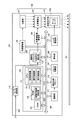
以下、添付図面を参照しながら本発明を適用した実施形態について説明する。図1に、本実施形態のプロジェクター100の全体構成の一例を示す。プロジェクター100は、パーソナルコンピューターや各種映像プレーヤー等の外部の画像供給装置(不図示)から供給される画像データに基づいて、スクリーンSCに画像を投射する。なお、以下の説明では、投射面としてスクリーンSCを例に説明するが、投射面はスクリーンSCに限定されず、ホワイトボードや部屋の壁等であってもよい。また、スクリーンSCは、枠辺を有していてもよいし、枠辺を有していなくてもよい。また、プロジェクター100がスクリーンSCに投射する画像データは、動画像(映像)のデータであってもよいし、静止画像のデータであってもよい。また、プロジェクター100は映像をスクリーンSCに投射することも、静止画像をスクリーンSCに投射し続けることも可能である。以下の実施形態では、外部の画像供給装置からケーブル200を介して入力されたアナログ画像信号に基づいて画像を投射する場合を例に挙げて説明する。
[First Embodiment]
Embodiments to which the present invention is applied will be described below with reference to the accompanying drawings. FIG. 1 shows an example of the overall configuration of the
プロジェクター100は、大きく分けて光学的な画像の形成を行う投射部150と、プロジェクター100の全体の動作を制御し、画像信号を電気的に変換する処理を行う画像処理系とを備える。投射部150は、光源部151と、光変調装置152と、投射光学系153とを備えている。
The
光源部151は、光源として、キセノンランプ、超高圧水銀ランプ、LED(Light Emitting Diode)、レーザー光源等を使用できる。なお、光源部151に、光源部151が発した光を光変調装置152に導くリフレクター及び補助リフレクター(不図示)や、光源部151が発した光を光変調装置152に至る経路上で減光させる調光素子(不図示)等を設けてもよい。
The
光変調装置152は、光源部151が発した光を、ダイクロイックミラー等によりR,G,Bの各色光に分離して、光変調装置152が備える複数(3枚)の液晶パネル(不図示)によって各色光を変調する。光変調装置152は、変調された各色光を、クロスダイクロイックプリズムにより合成して、投射光学系153に出力する。液晶パネルの備えるパネル面には、光変調装置駆動部141の駆動により画像信号に基づく画像(以下、パネル画像という)が形成される。光源部151が発した光は、液晶パネルに形成されたパネル画像によって画像を表す画像光へと変調される。液晶パネルにおいて変調された画像光は、投射光学系153を介してスクリーンSCへと投射される。
なお、本実施形態では、光源が発した光を変調する光変調装置152として、RGBの各色に対応した3枚の透過型の液晶パネルを用いた構成を例に挙げるが、これに限定されるものではない。例えば3枚の反射型の液晶パネルを用いることも可能である。また、光変調装置112は、1枚の液晶パネルとカラーホイールを組み合わせた方式、3枚のDMD(Digital Mirror Device)を用いた方式、1枚のDMDとカラーホイールを組み合わせた方式等により構成してもよい。ここで、光変調装置112として1枚のみの液晶パネルまたはDMDを用いる場合には、クロスダイクロイックプリズム等の合成光学系に相当する部材は不要である。また、液晶パネル及びDMD以外にも、光源が発した光を変調可能な構成であれば問題なく採用できる。
The
In the present embodiment, the
投射光学系153は、投射する画像の拡大・縮小及び焦点の調整を行うズームレンズ1531を備えている。投射光学系153には、光変調装置152で変調された光が入射され、この光がズームレンズ1531を経てスクリーンSC上に投射され、投射画像を結像する。ズームレンズ1531は、複数のレンズを含むレンズ群により構成される。ズームレンズ1531を、後述するレンズ駆動部143によって駆動し、各レンズの位置調整等を行うことで、スクリーンSC上の投射画像の拡大・縮小を行うズーム調整や、スクリーンSC上に投射画像を適正に結像させるフォーカス調整が行われる。
The projection
画像処理系は、プロジェクター100の全体を統合的に制御する制御部120と、画像用プロセッサー130とを中心に構成される。画像処理系には、その他に、A/D(Analog-to-Digital)変換部110、光変調装置駆動部141、光源駆動部142、レンズ駆動部143等が設けられている。また、画像処理系は、CCD(Charge Coupled Device)カメラを備えた撮像部171、撮影画像メモリー172、リモコン制御部181、操作部182等を備えている。これらの画像処理系を構成する各要素は、バス105を介して互いに接続されている。
The image processing system includes a
A/D変換部110は、上述した外部の画像供給装置からケーブル200を介して入力したアナログ画像信号をA/D変換するデバイスである。A/D変換部110は、アナログ画像信号をデジタル画像信号に変換し、変換したデジタル画像信号を画像用プロセッサー130に出力する。
The A /
制御部120は、CPU(Central Processing Unit)121、ROM(Read Only Memory)122、RAM(Random Access Memory)123を備えている。
CPU121は、ROM122、RAM123等と共に制御部120を構成し、プロジェクター100を統括制御する。CPU121、RAM123等のハードウェアと、ROM122に記憶したプログラムとの協働によって、図1に示すCPU121内に示す機能ブロックが実現される。本実施形態の制御部120は、機能ブロックとして、投射制御部1211、撮影制御部1212、補正制御部1213を備えている。これら各部の詳細については後述する。
The
The
ROM122は、上述した各処理部を実現するためにCPU121が実行するプログラム等を記憶する。また、ROM122には、枠辺検出用画像や、投射角測定用画像を記憶する調整用画像記憶部1221が設けられている。枠辺検出用画像は、スクリーンSCの枠辺(枠状の境界線)を検出する際に使用される画像である。投射角測定用画像は、プロジェクター100の投射光の光軸に対するスクリーンSCの傾きである投射角度の算出に用いられる。図2に、枠辺検出用画像の一例を示す。図2に示す枠辺検出用画像は、画像の中央部分が白色で形成され、その周りを囲む周辺部分が黒色で形成された画像である。また、図3に、投射角測定用画像の例を示す。図3(A)に第1投射角測定用画像を示し、図3(B)に第2投射角測定用画像を示し、図3(C)に第3投射角測定用画像を示す。投射角測定用画像には、少なくとも3点(図3(A)〜図3(C)に示す第1〜第3投射角測定用画像には4点の測定点が含まれる。これらの測定点は、スクリーンSCに投射された際に、3点が同一直線上に存在しないような位置に配置されている。第1投射角測定用画像は、測定点間の距離が最も長い画像であり、第3投射角測定用画像は、測定点間の距離が最も短い画像である。第2投射角測定用画像は、測定点間の距離が、第1投射角測定用画像と第3投射角測定用画像との中間の画像である。すなわち、第1、第2、第3投射角測定用画像の横方向の測定点間の距離をそれぞれX1、X2、X3とした場合、X1>X2>X3となる。同様に、第1、第2、第3投射角測定用画像の縦方向の測定点間の距離をそれぞれY1、Y2,Y3とした場合、Y1>Y2>Y3となる。なお、図3に示す投射角測定用画像では、背景部を斜線で示しているが、背景部は黒色であるとよい。
The
RAM123は、CPU121や画像用プロセッサー130が実行するプログラムやデータを一時的に格納するワークエリアを形成する。なお、画像用プロセッサー130は、自身が行う画像の表示状態の調整処理など、各処理の実行の際に必要となるワークエリアを、内蔵RAMとして備えていてもよい。
The
画像用プロセッサー130は、A/D変換部110から入力された画像データを処理する機能部である。画像用プロセッサー130は、投射対象の画像データに対して、輝度、コントラスト、色の濃さ、色合い等の画像の表示状態を調整する処理を行って、処理後の画像データを光変調装置駆動部141に出力する。なお、画像用プロセッサー130は、台形歪み補正用や画像処理用のDSP(Digital Signal processor)として汎用されているプロセッサーを用いて構成することも可能である。また、画像用プロセッサー130は、専用のASIC(Application Specific Integrated Circuit)として構成することも可能である。
画像用プロセッサー130は、台形歪み補正部131を備えている。台形歪み補正部131は、補正制御部1213から入力したパラメーターに従って、A/D変換部110が出力した画像データの画像を変形させる処理を行う。
The
The
光変調装置駆動部141は、画像用プロセッサー130から入力した画像信号に基づいて光変調装置152を駆動する。これにより、画像信号に応じたパネル画像が、光変調装置152の備える液晶パネルのパネル面に形成され、このパネル画像が投射光学系153によりスクリーンSCに投射される。
The light
光源駆動部142は、制御部120から入力した指示信号に従って光源部151に電圧を印加し、光源部151を点灯又は消灯させる。
The light
レンズ駆動部143は、投射光学系153が備えるズームレンズ1531を駆動して、ズーム状態を変化させることができる。ズーム状態とは、投射光学系153において、光変調装置152を透過した光を投写する際の拡大の程度(倍率)を意味している。すなわち、レンズ駆動部143は、ズームレンズ1531を駆動してスクリーンSC上に表示させる画像の大きさを変化させることができる。
The
撮像部171は、プロジェクター100の前面、即ち、投射光学系153がスクリーンSCに向けて画像を投射する方向、範囲(投射範囲)を撮像可能な位置に設けられている。撮像部171は、所定の投射距離においてスクリーンSC上に投射された投射画像の全体が少なくとも撮像範囲内に入るように、撮影方向及び画角が設定されている。
撮像部171により撮影された撮影画像データは、撮像部171から撮影画像メモリー172に出力され、撮影画像メモリー172の所定の領域に書き込まれる。撮影画像メモリー172は、1画面分の画像データの書き込みが完了すると、所定の領域のフラグを順次反転するので、制御部120は、このフラグを参照することにより、撮像部171を用いた撮像が完了したか否かを知ることができる。制御部120は、このフラグを参照しつつ、撮影画像メモリー172にアクセスして、必要な撮影画像データを取得する。
The
The captured image data captured by the
リモコン制御部181は、プロジェクター100の外部のリモコン(不図示)から送信される無線信号を受信する。リモコンは、ユーザーによって操作される操作子(不図示)を備え、操作子に対する操作に応じた操作信号を赤外線信号又は所定周波数の電波を用いた無線信号として送信する。リモコン制御部181は、赤外線信号を受信する受光部(不図示)や無線信号を受信する受信回路(不図示)を備え、リモコンから送信された信号を受信して解析し、ユーザーによる操作の内容を示す信号を生成して制御部120に出力する。
The remote
操作部182は、例えばプロジェクター100の本体に配置された操作パネルの操作子(不図示)により構成される。操作部182は、上記操作子に対する操作を検出すると、操作子に対応する操作信号を制御部120に出力する。この操作子としては、電源ON/OFFを指示するスイッチや、歪み補正処理開始を指示するスイッチ等がある。
The
ここで、制御部120の備える機能ブロックについて説明する。
投射制御部1211は、A/D変換部110が出力する画像データに基づいて、投射部150により画像を投射する動作を制御する。具体的には、投射制御部1211は、プロジェクター100の電源オン又はオフに伴い光源駆動部142により光源部151を点灯又は消灯させる制御、A/D変換部110が出力する画像データを画像用プロセッサー130により処理させる制御等を行う。投射制御部1211は、操作部182又はリモコンの操作により台形歪み補正処理の開始が指示されると、調整用画像記憶部1221に記憶された枠辺検出用画像を読み出してスクリーンSCに投射させる。また、投射制御部1211は、補正制御部1213によって選択された投射角測定用画像を調整用画像記憶部1221から読み出してスクリーンSCに投射させる。投射制御部1211は、読み出した画像をコマンドと共に画像用プロセッサー130に出力する。枠辺検出用画像又は投射角測定用画像は、投射制御部1211の制御する光変調装置駆動部141によって光変調装置152の液晶パネルに表示され、スクリーンSCに投射される。
Here, functional blocks provided in the
The
撮影制御部1212は、撮像部171を制御して、スクリーンSCに投射された投射画像を撮影させる。撮像部171により撮影された撮影画像データは、撮影画像メモリー172に記憶される。
The
補正制御部1213は、撮影画像メモリー172に記憶された撮影画像データを取得して、スクリーンSCの枠辺を検出する。撮影画像メモリー172には、枠辺検出用画像を撮影した撮影画像データが記憶されている。補正制御部1213は、撮影画像メモリー172から撮影画像データを取得して、取得した撮影画像データに画像処理を施してスクリーンSCの枠辺の座標値を検出する。補正制御部1213は、例えば、特開2008−211355号公報に開示された検出方法を用いてスクリーンSCの枠辺の座標値を検出する。なお、検出される座標値は、撮影画像メモリー172に描画した撮影画像データにおける座標値である。補正制御部1213は、スクリーンSCの枠辺を検出した場合には、枠辺ありを示す情報と、枠辺の座標値とをRAM123に記憶させる。また、補正制御部1213は、スクリーンSCの枠辺を検出することができなかった場合には、枠辺なしを示す情報をRAM123に記憶させる。
なお、補正制御部1213による枠辺の座標値の検出方法は、特開2008−211355号公報に開示された検出方法に限定されるものではない。例えば、補正制御部1213は、スクリーンSCを撮影した撮影画像データに対してエッジ抽出フィルターを適用し、スクリーンSCの枠辺を境界線として検出してもよい。エッジ抽出フィルターとしては、微分フィルター、ラプラシアンフィルター等の画像の輪郭を抽出することが可能な種々のフィルターを用いることができる。
The
Note that the detection method of the frame side coordinate values by the
また、補正制御部1213は、スクリーンSCの枠辺の検出結果に基づいて、スクリーンSCに投射する投射角測定用画像を選択する。補正制御部1213によって選択された投射角測定用画像は、投射制御部1211によってスクリーンSCに投射され、撮影制御部1212によって撮影される。補正制御部1213は、投射角測定用画像の撮影画像データに含まれる測定点のうち、枠辺の検出結果に対応する位置に投射される測定点を用いて投射角度を測定する。測定点の選択方法の具体例については、図4を参照しながら説明する。また、投射角度の測定については、補正制御部1213は、投射角測定用画像の撮影画像データに含まれる測定点を少なくとも3点選択し、選択した測定点に対する3次元測量の結果に基づいて算出する。
また、補正制御部1213は、算出した投射角度及び枠辺の座標値、又は投射角度を用いて台形歪みを補正する補正係数を算出する。補正制御部1213は、算出した補正係数を画像用プロセッサー130に渡し、画像用プロセッサー130に、補正係数に基づく入力画像の台形歪み補正を行わせる。
The
Further, the
次に、本実施形態の処理手順を図4に示すフローチャートを参照しながら説明する。本フローは、台形歪み補正の開始の指示(ユーザーによるボタン操作時、電源オン時、初期画面投写時)とともに始まる。制御部120は、まず、台形歪み補正の開始を指示する操作を入力したか否かを判定する(ステップS1)。開始を指示する操作を入力した場合(ステップS1/YES)、制御部120は、投射制御部1211の制御により、枠辺検出用画像をスクリーンSCに表示させる(ステップS2)。制御部120の投射制御部1211は、枠辺検出用画像を調整用画像記憶部1221から読み出し、読み出した枠辺検出用画像を画像用プロセッサー130にコマンドとともに出力する。枠辺検出用画像は、投射制御部1211の制御する光変調装置駆動部141によって光変調装置152の液晶パネルに表示され、スクリーンSCに投射される(ステップS2)。
Next, the processing procedure of this embodiment will be described with reference to the flowchart shown in FIG. This flow starts with an instruction to start trapezoidal distortion correction (when the user operates a button, when the power is turned on, or when the initial screen is projected). The
次に、スクリーンSCに枠辺検出用画像が投射された状態で、制御部120は、撮影制御部1212の制御により撮像部171に撮影を実行させる。撮像部171は、スクリーンSCに投射された枠辺検出用画像を撮影し、撮影した撮影画像データを撮影画像メモリー172に記憶させる。
次に、制御部120は、補正制御部1213の制御により撮影画像データを撮影画像メモリー172から読み出して取得する(ステップS3)。次に、制御部120は、補正制御部1213の制御により取得した撮影画像データに対して画像処理を施して枠辺を検出する(ステップS4)。補正制御部1213は、スクリーンSCの枠辺を検出した場合には、枠辺ありを示す情報と、枠辺の座標値とをRAM123に記憶させる。また、補正制御部1213は、スクリーンSCの枠辺を検出することができなかった場合には、枠辺なしを示す情報をRAM123に記憶させる。
また、補正制御部1213は、枠辺を検出することができた場合(ステップS5/YES)、検出した枠辺の座標値に基づいて、投射角測定用画像を選択する(ステップS6)。すなわち、補正制御部1213は、検出した枠辺の座標値に基づいて、枠辺内に測定点を表示可能であって、測定点間の距離が最大の投射角測定用画像を選択する(ステップS6)。なお、液晶パネルに形成した枠辺検出画像の座標と撮影画像に写った枠辺検出画像の座標値とから、液晶パネル上の座標系と撮影画像上の座標系との1対1の対応関係が得られる。このため、この対応関係を用いて、検出した枠辺の座標値と測定点との位置とを比較することができる。
また、補正制御部1213は、枠辺を検出することができなかった場合には(ステップS5/NO)、調整用画像記憶部1221に記憶した投射角測定用画像のうち、測定点間の距離が最も長い投射角測定用画像を選択する(ステップS7)。例えば、図3(A)に示す第1投射角測定用画像が選択される。
Next, in a state where the frame side detection image is projected on the screen SC, the
Next, the
If the frame side can be detected (step S5 / YES), the
If the
補正制御部1213によって投射角測定用画像が選択されると、制御部120は、投射制御部1211の制御により、選択された投射角測定用画像を調整用画像記憶部1221から読み出して、スクリーンSCに投射させる(ステップS8)。
次に、スクリーンSCに投射角測定用画像が投射された状態で、制御部120は、撮影制御部1212の制御によりスクリーンSCに投射された投射角測定用画像を撮像部171に撮影させ、撮影された撮影画像データを撮影画像メモリー172に記憶させる。
撮影画像データが撮影画像メモリー172に記憶されると、制御部120は、補正制御部1213の制御により撮影画像メモリー172から撮影画像データを取得する(ステップS9)。制御部120は、補正制御部1213の制御により、取得した撮影画像データに基づいて3次元測量を行い、投射角度を算出する(ステップS10)。
When a projection angle measurement image is selected by the
Next, in a state where the projection angle measurement image is projected on the screen SC, the
When the captured image data is stored in the captured
次に、制御部120は、ステップS5において枠辺の座標値を検出している場合には、補正制御部1213の制御により、算出した投射角度と枠辺の座標値とを用いて台形歪みを補正する補正係数を算出する(ステップS11)。具体的には、補正制御部1213は、検出したスクリーンSCの枠辺の座標値を用いて、投射画像の形状がスクリーンの枠辺の形状に一致するように補正する補正係数を算出する。また、制御部120は、ステップS5において枠辺の座標値を検出していない場合、補正制御部1213の制御により、算出した投射角度に基づいて、台形歪みを補正する補正係数を算出する(ステップS11)。制御部120は、補正係数を算出すると、算出した補正係数を画像用プロセッサー130に渡し、画像用プロセッサー130に、補正係数に基づく入力画像の台形歪み補正を行わせる(ステップS12)。画像用プロセッサー130によって台形歪みを補正された画像は、投射制御部1211の制御により、スクリーンSCに投射される(ステップS12)。
Next, when the coordinate value of the frame side is detected in step S5, the
投射面が、枠辺を有するスクリーンSCの場合、投射画像がスクリーンSCの枠辺に沿うように台形歪み補正を行えばよいため、投射角度の測定精度は、枠辺を有していない場合の測定精度に比べて高い精度を要求されない。このため、本実施形態は、スクリーンSCが枠辺を有している場合には、投射制御部1211が、スクリーンSCの枠辺内に測定点が表示され、かつ測定点間の距離が最も長い投射角測定用画像を選択してスクリーンSCに投射させる。そして、補正制御部1213が、投射角測定用画像を撮影した撮影画像データから投射角度を算出する。また、投射面が、枠辺を有しないスクリーンSCである場合には、投射角度だけを用いて台形歪み補正を行う必要があるため、高い投射角度の測定精度が要求される。このため、本実施形態は、投射面が枠辺を有しないスクリーンSCである場合には、投射制御部1211が、調整用画像記憶部1221の記憶する投射角測定用画像の中から、測定点間の距離が最も長い投射角測定用画像を選択する。すなわち、投射制御部1211は、図3に示す第1投射角測定用画像を選択してスクリーンSCに投射させる。そして、補正制御部1213が、投射角測定用画像を撮影した撮影画像データから投射角度を算出する。
このように本実施形態は、枠辺の有無に応じて最適な投射角測定用画像を選択してスクリーンSCに投射し、スクリーンSCの投射角度を算出することができる。このため、投射角度の測定精度を、スクリーンSCの枠辺の有無に応じて変更することができ、台形歪み補正を精度よく行うことができる。
In the case where the projection surface is a screen SC having a frame side, it is only necessary to perform trapezoidal distortion correction so that the projected image is along the frame side of the screen SC. High accuracy compared to measurement accuracy is not required. For this reason, in this embodiment, when the screen SC has a frame side, the
As described above, according to the present embodiment, an optimal projection angle measurement image can be selected and projected on the screen SC according to the presence or absence of the frame side, and the projection angle of the screen SC can be calculated. For this reason, the measurement accuracy of the projection angle can be changed according to the presence or absence of the frame side of the screen SC, and the trapezoidal distortion correction can be performed with high accuracy.
[変形例]
第1実施形態では、スクリーンSCに枠辺が存在すると判定した場合には、補正制御部1213が、事前に用意された投射角測定用画像の中から測定点が枠辺内に収まり、測定点間の距離が最も長い投射角測定用画像を選択してスクリーンSCに投射していた。
本変形例では、スクリーンSCに投射された枠辺検出用画像を撮影した撮影画像データに基づいてスクリーンSCの枠辺が検出されると、補正制御部1213が、検出した枠辺の座標値に基づいて、投射角測定用画像を生成する。補正制御部1213は、検出した枠辺の座標値に基づいて、枠辺内に収まるように測定点が配置された投射角測定用画像を生成する。投射角測定用画像には、第1実施形態で説明したように、少なくとも3点の測定点が含まれる。これらの測定点は、スクリーンSCに投射された際に、3点が同一直線上に存在しないような位置に配置されている。また、測定点は、スクリーンSCに投射された際に、測定点間の距離が、スクリーンSCの枠内で可能な限り大きくなるように配置されている。生成した投射角測定用画像は、投射制御部1211の制御によりスクリーンSCに投射され、投射角測定用画像を撮影した撮影画像データに基づいて補正制御部1213の制御により投射角度が算出される。
また、スクリーンSCに枠辺が検出されない場合には、補正制御部1213は、光変調装置152の備える液晶パネルのパネル面において、測定点間の距離を可能な限り離間させた投射角測定用画像を生成する。生成した投射角測定用画像は、投射制御部1211の制御によりスクリーンSCに投射され、投射角測定用画像を撮影した撮影画像データに基づいて補正制御部1213の制御により投射角度が算出される。
このように本変形例は、スクリーンSCの枠辺の有無に応じて、測定点間の距離を変更した投射角測定用画像を生成してスクリーンSCに投射し、スクリーンSCの投射角度を算出する。このため、投射角度の測定精度を、スクリーンSCの枠辺の有無に応じて変更することができ、台形歪み補正を精度よく行うことができる。
[Modification]
In the first embodiment, when it is determined that the frame side exists on the screen SC, the
In this modification, when the frame side of the screen SC is detected based on the captured image data obtained by capturing the frame side detection image projected on the screen SC, the
When the frame side is not detected on the screen SC, the
As described above, in this modification, a projection angle measurement image in which the distance between the measurement points is changed according to the presence or absence of the frame side of the screen SC is generated and projected onto the screen SC, and the projection angle of the screen SC is calculated. . For this reason, the measurement accuracy of the projection angle can be changed according to the presence or absence of the frame side of the screen SC, and the trapezoidal distortion correction can be performed with high accuracy.
[第2実施形態]
次に、添付図面を参照しながら本発明の第2実施形態について説明する。なお、本実施形態のハードウェア構成は、図1に示す第1実施形態の構成と同一であるため、図示及びその説明を省略する。
[Second Embodiment]
Next, a second embodiment of the present invention will be described with reference to the accompanying drawings. The hardware configuration of this embodiment is the same as that of the first embodiment shown in FIG.
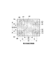
図5に、本実施形態の投射角測定用画像の一例を示す。本実施形態の投射角測定用画像は、測定点として測定点A1〜A4(測定点群A)と、測定点B1〜B4(測定点群B)と、測定点C1〜C4(測定点群C)とを有している。本実施形態では、図3(A)に示す第1投射角測定用画像と、図3(B)に示す第2投射角測定用画像と、図3(C)に示す第3投射角測定用画像とを合成した画像を投射角測定用画像として用いる。
測定点A1及びA2と、測定点A3及びA4とは、投射角測定用画像の横方向においてX4だけ離れている。また、測定点A1及びA4と、測定点A2及びA3とは、投射角測定用画像の縦方向においてY4だけ離れている。測定点B1及びB2と、測定点B3及びB4とは、投射角測定用画像の横方向においてX5だけ離れている。また、測定点B1及びB4と、測定点B2及びB3とは、投射角測定用画像の縦方向においてY5だけ離れている。測定点C1及びC2と、測定点C3及びC4とは、投射角測定用画像の横方向においてX6だけ離れている。また、測定点C1及びC4と、測定点C2及びC3とは、投射角測定用画像の縦方向においてY6だけ離れている。なお、X4<X5<X6の関係にあり、Y4<Y5<Y6の関係にある。
FIG. 5 shows an example of the projection angle measurement image of the present embodiment. The projection angle measurement image of this embodiment includes measurement points A1 to A4 (measurement point group A), measurement points B1 to B4 (measurement point group B), and measurement points C1 to C4 (measurement point group C) as measurement points. ). In the present embodiment, the first projection angle measurement image shown in FIG. 3 (A), the second projection angle measurement image shown in FIG. 3 (B), and the third projection angle measurement image shown in FIG. 3 (C). An image synthesized with the image is used as a projection angle measurement image.
The measurement points A1 and A2 and the measurement points A3 and A4 are separated by X4 in the horizontal direction of the projection angle measurement image. Further, the measurement points A1 and A4 and the measurement points A2 and A3 are separated by Y4 in the vertical direction of the projection angle measurement image. Measurement points B1 and B2 and measurement points B3 and B4 are separated by X5 in the horizontal direction of the projection angle measurement image. Further, the measurement points B1 and B4 and the measurement points B2 and B3 are separated by Y5 in the vertical direction of the projection angle measurement image. The measurement points C1 and C2 and the measurement points C3 and C4 are separated by X6 in the horizontal direction of the projection angle measurement image. Further, the measurement points C1 and C4 and the measurement points C2 and C3 are separated by Y6 in the vertical direction of the projection angle measurement image. Note that X4 <X5 <X6 and Y4 <Y5 <Y6.
本実施形態は、枠辺の検出結果に応じて投射する投射角測定用画像を変更するのではなく、枠辺の検出結果に拘らずに投射される共通の投射角測定用画像から、枠辺の検出結果に応じた測定点群を選択し、選択した測定点群を用いて投射角度を算出する。なお、図5に示す投射角測定用画像も、背景部を斜線で示しているが、背景部は黒色であるとよい。 This embodiment does not change the projection angle measurement image to be projected according to the detection result of the frame side, but from the common projection angle measurement image to be projected regardless of the detection result of the frame side. A measurement point group corresponding to the detection result is selected, and a projection angle is calculated using the selected measurement point group. In the projection angle measurement image shown in FIG. 5, the background portion is indicated by diagonal lines, but the background portion may be black.
本実施形態の処理手順を図6に示すフローチャートを参照しながら説明する。なお、図6に示すS21〜S24までの処理手順は、図4に示すS1〜S4までの手順と同一であるため説明を省略する。
ステップS24において、制御部120は、補正制御部1213の制御により、撮影画像データを撮影画像メモリー172から読み出し、読み出した撮影画像データに対して画像処理を施すことにより枠辺を検出する(ステップS24)。なお、補正制御部1213は、スクリーンSCの枠辺を検出した場合には、枠辺ありを示す情報と、枠辺の座標値とをRAM123に記憶させる。また、補正制御部1213は、スクリーンSCの枠辺を検出することができなかった場合には、枠辺なしを示す情報をRAM123に記憶させる。
The processing procedure of this embodiment will be described with reference to the flowchart shown in FIG. The processing procedure from S21 to S24 shown in FIG. 6 is the same as the procedure from S1 to S4 shown in FIG.
In step S24, the
次に、制御部120は、投射制御部1211の制御により、投射角測定用画像を調整用画像記憶部1221から読み出して、スクリーンSCに投射させる(ステップS25)。すなわち、制御部120は、投射制御部1211により投射角測定用画像を調整用画像記憶部1221から読み出し、読み出した投射角測定用画像を画像用プロセッサー130にコマンドとともに出力する。投射角測定用画像は、投射制御部1211の制御する光変調装置駆動部141によって光変調装置152の液晶パネルに表示され、スクリーンSCに投射される(ステップS25)。次に、スクリーンSCに投射角測定用画像が投射された状態で、制御部120は、撮影制御部1212により撮像部171を制御して、撮影を実行する。撮像部171は、撮影制御部1212の制御によりスクリーンSCに投射された投射角測定用画像を撮影し、撮影した撮影画像データを撮影画像メモリー172に記憶させる。補正制御部1213は、撮影画像メモリー172に記憶された撮影画像データを取得する(ステップS26)。
Next, under the control of the
次に、制御部120は、補正制御部1213の制御によりステップS24でRAM123に記憶させた枠辺の有無を示す情報と、枠辺を検出した場合には枠辺の座標値とに基づいて、投射角度の測定に使用する測定点群を選択する。すなわち、補正制御部1213は、投射角測定用画像の撮影画像データに写った測定点群から、投射角度の算出に使用する測定点群を選択する。補正制御部1213は、枠辺の有無を示す情報として枠辺なしを示す情報がRAM123に記憶されていた場合には、測定点間の距離が最も長い測定点群(測定点群C)を選択する(ステップS27)。また、補正制御部1213は、枠辺ありを示す情報がRAM123に記憶されていた場合には、RAM123に記憶された枠辺の座標値に基づいて、枠辺内に表示可能であって、測定点間の距離が最も長い測定点群を選択する(ステップS27)。すなわち、補正制御部1213は、各測定点の座標値と、枠辺の座標値とを比較して、枠辺内に収まる測定点群であって、測定点間の距離が最も長い測定点群を選択する。
Next, the
次に、制御部120は、補正制御部1213の制御により、選択した測定点群に含まれる測定点に基づいて3次元測量を行い、投射角度を算出する(ステップS28)。次に、制御部120は、ステップS24において枠辺の座標値を検出している場合には、補正制御部1213の制御により、算出した投射角度と枠辺の座標値とを用いて台形歪みを補正する補正係数を算出する(ステップS29)。具体的には、補正制御部1213は、検出したスクリーンSCの枠辺の座標値を用いて、投射画像の形状がスクリーンの枠辺の形状に一致するように補正する補正係数を算出する。また、制御部120は、ステップS24において枠辺の座標値を検出していない場合、補正制御部1213の制御により、算出した投射角度に基づいて、台形歪みを補正する補正係数を算出する(ステップS29)。制御部120は、補正係数を算出すると、算出した補正係数を画像用プロセッサー130に渡し、画像用プロセッサー130に、補正係数に基づく入力画像の台形歪み補正を行わせる(ステップS30)。画像用プロセッサー130によって台形歪みを補正された画像は、投射制御部1211の制御により、スクリーンSCに投射される(ステップS30)。
なお、第2実施形態では、投写角度の算出に用いる測定点を、測定点群単位で選択するようにしているが、スクリーンSCの枠辺の検出結果に基づいて測定点を個別に選択する態様とすることも可能である。
Next, the
In the second embodiment, the measurement points used for calculating the projection angle are selected in units of measurement point groups. However, the measurement points are individually selected based on the detection results of the frame sides of the screen SC. It is also possible.
以上説明したように本実施形態は、投射面が、枠辺を有するスクリーンSCである場合には、投射角測定用画像の撮影画像データから、枠辺内に表示される測定点を選択して投射角度を測定する。また、投射面が、枠辺を有しないスクリーンSCである場合には、投射角測定用画像の撮影画像データから、測定点間の距離が最も長い測定点を選択して投射角度を測定する。このため、投射角度の測定精度を、スクリーンSCの枠辺の有無に応じて変更することができ、台形歪み補正を精度よく行うことができる。 As described above, in the present embodiment, when the projection surface is the screen SC having a frame side, the measurement point displayed in the frame side is selected from the captured image data of the projection angle measurement image. Measure the projection angle. Further, when the projection surface is the screen SC having no frame side, the projection angle is measured by selecting the measurement point having the longest distance between the measurement points from the captured image data of the projection angle measurement image. For this reason, the measurement accuracy of the projection angle can be changed according to the presence or absence of the frame side of the screen SC, and the trapezoidal distortion correction can be performed with high accuracy.
本実施形態のプロジェクター100は、投射光学系153と、補正制御部1213と、投射制御部1211とを備えている。投射光学系153は、スクリーンSCに画像を投射する。補正制御部1213は、投射光学系153の投射範囲で枠を検出する。投射制御部1211は、複数の測定点を含む投射角測定用画像を投射光学系153によって投射させる。また、補正制御部1213は、投射光学系153により投射された投射角測定用画像に含まれる測定点を検出して、投射光学系153の投射光の光軸に対する投射面の傾きである投射角度を測定する。また、補正制御部1213は、枠の検出結果に対応する位置に投射される測定点を用いて投射角度を測定する。従って、枠の有無に応じて、投射角度の測定に使用する測定点の位置を変更することで、枠の有無によらず台形歪みを精度よく補正することができる。
The
また、本実施形態のプロジェクター100は、測定点間の距離が異なる複数の測定点を含む投射角測定用画像を記憶する調整用画像記憶部1221を備えている。そして、投射制御部1211は、補正制御部1213の検出結果に基づいて投射角測定用画像を選択して投射する。従って、枠の検出結果に応じた投射角測定用画像をスクリーンSCに投射することができる。
In addition, the
また、本実施形態のプロジェクター100において、投射制御部1211は、枠が検出された場合には、検出された枠が大きいほど、測定点間の距離が長い測定用画像を選択して投射させる。従って、枠が検出された場合の投射角度の測定精度を高めることができる。
In the
また、本実施形態のプロジェクター100において、投射制御部1211は、枠が検出されていない場合には、測定点間の距離が最も長い測定用画像を選択して投射させる。従って、枠が検出されない場合の投射角度の測定精度を高めることができる。
In the
また、本実施形態のプロジェクター100において、投射制御部1211は、枠の検出結果に拘らずに共通の測定用画像を投射させる。補正制御部1213は、共通の測定用画像に含まれる複数の測定点のうち、枠の検出結果に対応する位置に投射される測定点を用いて投射角度を測定する。従って、枠の検出結果に基づいて、複数の測定点の中から測定点を選択し、選択した測定点を用いて投射角度を測定することで、台形歪みの補正精度を高めることができる。
In the
また、本実施形態のプロジェクター100において、投射制御部1211は、共通の測定用画像として、測定点間の距離が異なる複数組の測定点群を含む測定用画像を投射させる。補正制御部1213は、枠が検出された場合には、スクリーンSCにおいて枠よりも内側に投射される測定点群のうち測定点間の距離が最も長い測定点群を用いて投射角度を測定する。従って、枠が検出された場合の投射角度の測定精度を高めることができる。
In the
また、本実施形態のプロジェクター100において、投射制御部1211は、共通の測定用画像として、測定点間の距離が異なる複数組の測定点群を含む測定用画像を投射させる。補正制御部1213は、枠が検出されていない場合には、スクリーンSCにおいて測定点間の距離が最も長い測定点群を用いて投射角度を測定する。従って、枠が検出されない場合の投射角度の測定精度を高めることができる。
In the
また、本実施形態のプロジェクター100において、投射制御部1211は、枠の検出結果に応じて、測定点間の距離を変更した測定用画像を生成してスクリーンSCに投射させる。従って、枠の有無に応じて、投射角度の測定に使用する測定点の位置を変更することで、枠の有無によらず台形歪みを精度よく補正することができる。
Moreover, in the
また、本実施形態のプロジェクター100において、投射制御部1211は、枠が検出された場合には、検出された枠が大きいほど、測定点間の距離が長い測定用画像を生成して投射させる。従って、枠が検出された場合の投射角度の測定精度を高めることができる。
In the
上述した実施形態は、本発明の好適な実施の形態である。但し、これに限定されるものではなく、本発明の要旨を逸脱しない範囲内において種々の変形実施が可能である。 The above-described embodiment is a preferred embodiment of the present invention. However, the present invention is not limited to this, and various modifications can be made without departing from the scope of the present invention.
100…プロジェクター、110…A/D変換部、120…制御部、121…CPU、122…ROM、123…RAM、130…画像用プロセッサー、131…台形歪み補正部(記憶部)、141…光変調装置駆動部、142…光源駆動部、143…レンズ駆動部、150…投射部、151…光源部、152…光変調装置、153…投射光学系(投射部)、171…撮像部、172…撮影画像メモリー、1211…投射制御部、1212…撮影制御部、1213…補正制御部(検出部、測定部)。
DESCRIPTION OF
Claims (10)
前記投射部の投射範囲で枠を検出する検出部と、
複数の測定点を含む測定用画像を前記投射部によって投射させる投射制御部と、
前記投射部により投射された前記測定用画像に含まれる測定点を検出して、前記投射部の投射光の光軸に対する前記投射面の傾きを測定する測定部と、を備え、
前記測定部は、前記検出部の検出結果に対応する位置に投射される測定点を用いて前記傾きを測定すること、
を特徴とするプロジェクター。 A projection unit that projects an image onto the projection surface;
A detection unit for detecting a frame in the projection range of the projection unit;
A projection control unit that projects a measurement image including a plurality of measurement points by the projection unit;
A measurement unit that detects a measurement point included in the measurement image projected by the projection unit and measures the inclination of the projection surface with respect to the optical axis of the projection light of the projection unit, and
The measurement unit measures the inclination using a measurement point projected at a position corresponding to a detection result of the detection unit;
Projector.
前記投射制御部は、前記検出部の検出結果に基づいて前記測定用画像を選択して投射させること、
を特徴とする請求項1記載のプロジェクター。 A storage unit for storing a plurality of measurement images having different distances between the measurement points;
The projection control unit selects and projects the measurement image based on the detection result of the detection unit,
The projector according to claim 1.
を特徴とする請求項2記載のプロジェクター。 When the frame is detected by the detection unit, the projection control unit selects and projects a measurement image having a longer distance between the measurement points as the detected frame is larger.
The projector according to claim 2.
を特徴とする請求項2又は3記載のプロジェクター。 The projection control unit selects and projects the measurement image having the longest distance between the measurement points when the frame is not detected by the detection unit;
The projector according to claim 2 or 3, wherein
前記測定部は、前記共通の測定用画像に含まれる複数の測定点のうち、前記検出部の検出結果に対応する位置に投射される測定点を用いて前記傾きを測定すること、
を特徴とする請求項1記載のプロジェクター。 The projection control unit projects a common measurement image regardless of the detection result of the detection unit,
The measurement unit measures the inclination using a measurement point projected at a position corresponding to a detection result of the detection unit among a plurality of measurement points included in the common measurement image;
The projector according to claim 1.
前記測定部は、前記検出部により前記枠が検出された場合には、前記投射面において前記枠よりも内側に投射される測定点群のうち前記測定点間の距離が最も長い測定点群を用いて前記傾きを測定すること、
を特徴とする請求項5記載のプロジェクター。 The projection control unit projects a measurement image including a plurality of sets of measurement points having different distances between the measurement points as the common measurement image,
The measurement unit, when the frame is detected by the detection unit, a measurement point group having the longest distance between the measurement points among the measurement point groups projected on the projection surface inside the frame. Measuring the tilt using,
The projector according to claim 5.
前記検出部により前記枠が検出されていない場合には、前記投射面において前記測定点間の距離が最も長い測定点群を用いて前記傾きを測定すること、
を特徴とする請求項5又は6記載のプロジェクター。 The projection control unit projects a measurement image including a plurality of sets of measurement points having different distances between the measurement points as the common measurement image,
When the frame is not detected by the detection unit, the inclination is measured using a measurement point group having the longest distance between the measurement points on the projection surface;
The projector according to claim 5 or 6.
を特徴とする請求項1記載のプロジェクター。 The projection control unit generates a measurement image in which the distance between the measurement points is changed according to the detection result of the frame of the detection unit, and causes the projection surface to project the measurement image.
The projector according to claim 1.
を特徴とする請求項8記載のプロジェクター。 When the frame is detected by the detection unit, the projection control unit generates and projects a measurement image with a longer distance between the measurement points as the detected frame is larger.
The projector according to claim 8.
前記投射面の投射範囲で枠を検出するステップと、
前記投射面に投射された前記測定用画像に含まれる測定点を検出して、投射光の光軸に対する前記投射面の傾きを測定するステップと、を有し、
前記測定するステップは、前記枠の検出結果に対応する位置に投射される測定点を用いて前記傾きを測定すること、
を特徴とするプロジェクターの制御方法。 Projecting a measurement image including a plurality of measurement points on a projection surface;
Detecting a frame in a projection range of the projection surface;
Detecting a measurement point included in the measurement image projected on the projection surface, and measuring the inclination of the projection surface with respect to the optical axis of the projection light, and
The measuring step includes measuring the inclination using a measurement point projected at a position corresponding to the detection result of the frame;
A projector control method characterized by the above.
Priority Applications (1)
| Application Number | Priority Date | Filing Date | Title |
|---|---|---|---|
| JP2014061568A JP6347126B2 (en) | 2014-03-25 | 2014-03-25 | Projector and projector control method |
Applications Claiming Priority (1)
| Application Number | Priority Date | Filing Date | Title |
|---|---|---|---|
| JP2014061568A JP6347126B2 (en) | 2014-03-25 | 2014-03-25 | Projector and projector control method |
Publications (2)
| Publication Number | Publication Date |
|---|---|
| JP2015186080A true JP2015186080A (en) | 2015-10-22 |
| JP6347126B2 JP6347126B2 (en) | 2018-06-27 |
Family
ID=54352175
Family Applications (1)
| Application Number | Title | Priority Date | Filing Date |
|---|---|---|---|
| JP2014061568A Expired - Fee Related JP6347126B2 (en) | 2014-03-25 | 2014-03-25 | Projector and projector control method |
Country Status (1)
| Country | Link |
|---|---|
| JP (1) | JP6347126B2 (en) |
Cited By (1)
| Publication number | Priority date | Publication date | Assignee | Title |
|---|---|---|---|---|
| EP4064696A2 (en) | 2021-03-22 | 2022-09-28 | Casio Computer Co., Ltd. | Projection control apparatus, terminal apparatus, and projection method |
Families Citing this family (1)
| Publication number | Priority date | Publication date | Assignee | Title |
|---|---|---|---|---|
| WO2017179111A1 (en) * | 2016-04-12 | 2017-10-19 | 日立マクセル株式会社 | Display system and information processing method |
Citations (3)
| Publication number | Priority date | Publication date | Assignee | Title |
|---|---|---|---|---|
| JP2005244955A (en) * | 2004-02-02 | 2005-09-08 | Sharp Corp | Projection system |
| JP2012018214A (en) * | 2010-07-06 | 2012-01-26 | Sanyo Electric Co Ltd | Projection type video display device |
| JP2012078683A (en) * | 2010-10-05 | 2012-04-19 | Seiko Epson Corp | Projector and trapezoidal distortion correction method |
-
2014
- 2014-03-25 JP JP2014061568A patent/JP6347126B2/en not_active Expired - Fee Related
Patent Citations (3)
| Publication number | Priority date | Publication date | Assignee | Title |
|---|---|---|---|---|
| JP2005244955A (en) * | 2004-02-02 | 2005-09-08 | Sharp Corp | Projection system |
| JP2012018214A (en) * | 2010-07-06 | 2012-01-26 | Sanyo Electric Co Ltd | Projection type video display device |
| JP2012078683A (en) * | 2010-10-05 | 2012-04-19 | Seiko Epson Corp | Projector and trapezoidal distortion correction method |
Cited By (2)
| Publication number | Priority date | Publication date | Assignee | Title |
|---|---|---|---|---|
| EP4064696A2 (en) | 2021-03-22 | 2022-09-28 | Casio Computer Co., Ltd. | Projection control apparatus, terminal apparatus, and projection method |
| US11822220B2 (en) | 2021-03-22 | 2023-11-21 | Casio Computer Co., Ltd. | Projection control apparatus, terminal apparatus, and projection method |
Also Published As
| Publication number | Publication date |
|---|---|
| JP6347126B2 (en) | 2018-06-27 |
Similar Documents
| Publication | Publication Date | Title |
|---|---|---|
| EP2826249B1 (en) | Projector and control method for the projector | |
| KR101631571B1 (en) | Projector and control method for the projector | |
| CN102457692B (en) | Projector and method of controlling projector | |
| JP6343910B2 (en) | Projector and projector control method | |
| JP5796286B2 (en) | Projector and projector control method | |
| KR101725512B1 (en) | Projector and method of controlling projector | |
| JP6624807B2 (en) | Image projection device and program | |
| JP6330292B2 (en) | Projector and projector control method | |
| JP5644618B2 (en) | projector | |
| JP2012018214A (en) | Projection type video display device | |
| JP6347126B2 (en) | Projector and projector control method | |
| JP2018142856A (en) | Projector, and method for controlling projector | |
| JP5845566B2 (en) | Projector and projector control method | |
| JP5845565B2 (en) | Projector and projector control method | |
| JP2017187572A (en) | Image projection device | |
| JP6245343B2 (en) | Projector and projector control method | |
| JP6119902B2 (en) | Projector and projector control method | |
| JP5887777B2 (en) | Projector and projector control method | |
| JP2021034891A (en) | Control device and control method used for capturing projected image |
Legal Events
| Date | Code | Title | Description |
|---|---|---|---|
| RD04 | Notification of resignation of power of attorney |
Free format text: JAPANESE INTERMEDIATE CODE: A7424 Effective date: 20160617 |
|
| RD03 | Notification of appointment of power of attorney |
Free format text: JAPANESE INTERMEDIATE CODE: A7423 Effective date: 20160628 |
|
| A621 | Written request for application examination |
Free format text: JAPANESE INTERMEDIATE CODE: A621 Effective date: 20170131 |
|
| A977 | Report on retrieval |
Free format text: JAPANESE INTERMEDIATE CODE: A971007 Effective date: 20170907 |
|
| A131 | Notification of reasons for refusal |
Free format text: JAPANESE INTERMEDIATE CODE: A131 Effective date: 20170926 |
|
| A521 | Request for written amendment filed |
Free format text: JAPANESE INTERMEDIATE CODE: A523 Effective date: 20171121 |
|
| TRDD | Decision of grant or rejection written | ||
| A01 | Written decision to grant a patent or to grant a registration (utility model) |
Free format text: JAPANESE INTERMEDIATE CODE: A01 Effective date: 20180501 |
|
| A61 | First payment of annual fees (during grant procedure) |
Free format text: JAPANESE INTERMEDIATE CODE: A61 Effective date: 20180514 |
|
| R150 | Certificate of patent or registration of utility model |
Ref document number: 6347126 Country of ref document: JP Free format text: JAPANESE INTERMEDIATE CODE: R150 |
|
| LAPS | Cancellation because of no payment of annual fees |