JP2015177902A - Endoscope system and endoscope - Google Patents
Endoscope system and endoscope Download PDFInfo
- Publication number
- JP2015177902A JP2015177902A JP2014056824A JP2014056824A JP2015177902A JP 2015177902 A JP2015177902 A JP 2015177902A JP 2014056824 A JP2014056824 A JP 2014056824A JP 2014056824 A JP2014056824 A JP 2014056824A JP 2015177902 A JP2015177902 A JP 2015177902A
- Authority
- JP
- Japan
- Prior art keywords
- endoscope
- power
- side connector
- processor
- distance
- Prior art date
- Legal status (The legal status is an assumption and is not a legal conclusion. Google has not performed a legal analysis and makes no representation as to the accuracy of the status listed.)
- Granted
Links
- 238000003384 imaging method Methods 0.000 claims abstract description 88
- 238000004891 communication Methods 0.000 claims abstract description 24
- 238000006073 displacement reaction Methods 0.000 claims abstract description 10
- 238000001514 detection method Methods 0.000 claims description 65
- 238000010248 power generation Methods 0.000 claims description 34
- 230000003287 optical effect Effects 0.000 claims description 25
- 238000005286 illumination Methods 0.000 claims description 19
- 230000007423 decrease Effects 0.000 claims description 7
- 230000008878 coupling Effects 0.000 claims description 4
- 238000010168 coupling process Methods 0.000 claims description 4
- 238000005859 coupling reaction Methods 0.000 claims description 4
- 230000003247 decreasing effect Effects 0.000 claims description 3
- 238000003780 insertion Methods 0.000 description 13
- 230000037431 insertion Effects 0.000 description 13
- 230000002265 prevention Effects 0.000 description 12
- 238000000034 method Methods 0.000 description 8
- 238000012545 processing Methods 0.000 description 7
- 230000005540 biological transmission Effects 0.000 description 6
- 238000010586 diagram Methods 0.000 description 5
- 230000010355 oscillation Effects 0.000 description 3
- 239000000523 sample Substances 0.000 description 3
- 230000008054 signal transmission Effects 0.000 description 3
- 238000005452 bending Methods 0.000 description 2
- 238000009434 installation Methods 0.000 description 2
- 238000002955 isolation Methods 0.000 description 2
- 238000003825 pressing Methods 0.000 description 2
- XLYOFNOQVPJJNP-UHFFFAOYSA-N water Substances O XLYOFNOQVPJJNP-UHFFFAOYSA-N 0.000 description 2
- 239000003990 capacitor Substances 0.000 description 1
- 230000000295 complement effect Effects 0.000 description 1
- 230000006866 deterioration Effects 0.000 description 1
- 230000005674 electromagnetic induction Effects 0.000 description 1
- 238000009413 insulation Methods 0.000 description 1
- 230000001678 irradiating effect Effects 0.000 description 1
- 238000012423 maintenance Methods 0.000 description 1
- 229910044991 metal oxide Inorganic materials 0.000 description 1
- 150000004706 metal oxides Chemical class 0.000 description 1
- 239000004065 semiconductor Substances 0.000 description 1
Images


Abstract
Description
本発明は、内視鏡システム及び内視鏡に係り、特に内視鏡挿入部の先端部に搭載された固体撮像素子の破損を防止する内視鏡システム及び内視鏡に関する。 The present invention relates to an endoscope system and an endoscope, and more particularly to an endoscope system and an endoscope that prevent damage to a solid-state imaging device mounted at a distal end portion of an endoscope insertion portion.
周知のように内視鏡システムは、体腔内を撮影するCCD(Charge Coupled Device:電荷結合素子)イメージセンサ等の固体撮像素子を備えた内視鏡(スコープ)と、内視鏡のコネクタが着脱可能に装着され、内視鏡から出力された画像データに画像処理を施して表示装置に出力する内視鏡用プロセッサ装置(以下、単にプロセッサ装置という)とを備える。 As is well known, an endoscope system includes an endoscope (scope) equipped with a solid-state imaging device such as a CCD (Charge Coupled Device) image sensor that images the inside of a body cavity, and a connector of the endoscope is attached and detached. An endoscopic processor device (hereinafter simply referred to as a processor device) that is mounted in such a manner that it performs image processing on image data output from the endoscope and outputs the processed image data to a display device.
特許文献1には、内視鏡のCCDイメージセンサを駆動するために必要な複数の電圧の電源(複数種の電源)を生成し、それらの電源からの電力を内視鏡に供給するプロセッサ装置が開示されている。また、内視鏡のCCDイメージセンサへの複数種の電源の投入順序及び投入間隔をCCDイメージセンサの種類に対応した順序及び間隔で制御することで、CCDイメージセンサの破損を防止することが開示されている。 Patent Document 1 discloses a processor device that generates a plurality of voltage power sources (a plurality of types of power sources) necessary for driving a CCD image sensor of an endoscope and supplies power from the power sources to the endoscope. Is disclosed. Further, it is disclosed that damage to the CCD image sensor is prevented by controlling the order and interval of turning on a plurality of types of power to the CCD image sensor of the endoscope according to the order and interval corresponding to the type of the CCD image sensor. Has been.
特許文献2には、レーザ光を発振するレーザ発振装置と、レーザ発振装置の装着部に着脱可能に装着されるレーザプローブとからなるレーザ手術装置において、レーザ発振装置の装着部にレーザプローブのコネクタが装着されたか否かを距離検出センサにより検出し、装着を検出した場合のみレーザプローブに出射するレーザ光の光路上からシャッタ体を退避させることが開示されている。これによって、レーザ発振装置の装着部へのレーザプローブの装着時において、レーザ光が漏れるという事態が防止される旨開示されている。 Japanese Patent Application Laid-Open No. 2003-259542 discloses a laser surgical apparatus that includes a laser oscillation device that oscillates laser light and a laser probe that is detachably attached to a mounting portion of the laser oscillation device. Is detected by a distance detection sensor, and the shutter body is retracted from the optical path of the laser beam emitted to the laser probe only when the attachment is detected. Accordingly, it is disclosed that a situation in which laser light leaks when a laser probe is mounted on a mounting portion of a laser oscillation device is prevented.
ところで、固体撮像素子の駆動のために複数の電圧の電源(複数種の電源)を要する場合には、通常、それらの複数種の電源から固体撮像素子への電力供給を開始する順序及び停止する順序が固体撮像素子の種類に対応して予め決められており、電力供給の停止は、一般的には電力供給の開始とは逆の順序で行われる。 By the way, when a plurality of voltage power sources (plural types of power sources) are required to drive the solid-state imaging device, the order of starting and stopping the power supply from the plurality of types of power sources to the solid-state imaging device is usually stopped. The order is determined in advance corresponding to the type of the solid-state imaging device, and the stop of power supply is generally performed in the reverse order to the start of power supply.
内視鏡システムにおいても、内視鏡の固体撮像素子が複数種の電源を要する場合には、固体撮像素子の破損を防止するために複数種の電源から固体撮像素子への電力供給の開始及び停止を規定の順序で行うことが望ましい。 Even in an endoscope system, when a solid-state image sensor of an endoscope requires a plurality of types of power supplies, in order to prevent damage to the solid-state image sensor, start of power supply from the plurality of types of power supplies to the solid-state image sensor and It is desirable to stop in a prescribed order.
内視鏡システムでは、通常、内視鏡の固体撮像素子の駆動に必要な電力はプロセッサ装置から供給されており、特許文献1に記載の内視鏡システムでは、プロセッサ装置に内視鏡のコネクタが接続されると、プロセッサ装置の複数種の電源から内視鏡の固体撮像素子への電力供給が規定の順序で開始され、固体撮像素子の駆動の停止がユーザにより指示されると、各電源から固体撮像素子への電力供給が規定の順序で停止される。これによって、固体撮像素子の破損が防止されている。 In an endoscope system, normally, power necessary for driving a solid-state imaging device of an endoscope is supplied from a processor device. In the endoscope system described in Patent Document 1, an endoscope connector is connected to the processor device. Is connected, the power supply from the plurality of types of power supplies of the processor device to the solid-state image sensor of the endoscope is started in a prescribed order, and when the user instructs to stop driving the solid-state image sensor, Power supply to the solid-state imaging device is stopped in a prescribed order. This prevents damage to the solid-state image sensor.
しかしながら、体腔内の観察時や観察終了後等に固体撮像素子への電源供給を停止させることなく、ユーザが不用意に内視鏡のコネクタをプロセッサ装置から取り外してしまうという事態が生じ得る。特許文献1では、このような事態を想定しておらず、このような事態が生じた場合には、複数種の電源から固体撮像素子への電力供給が略同時に停止し、規定の順序で停止しないため、固体撮像素子が破損してしまう可能性が生じていた。 However, a situation may occur in which the user inadvertently removes the connector of the endoscope from the processor device without stopping the power supply to the solid-state imaging device at the time of observation in the body cavity or after the observation is completed. In Patent Document 1, such a situation is not assumed, and when such a situation occurs, power supply from a plurality of types of power supplies to the solid-state imaging device is stopped almost simultaneously and stopped in a prescribed order. Therefore, there is a possibility that the solid-state imaging device is damaged.
特許文献2は、コネクタの着脱を検知してシャッタの開閉動作のトリガとするものであるが、内視鏡システムへの適用は示唆されておらず、特に、内視鏡の固体撮像素子の破損を防止するための電源制御への適用も示唆されていない。 Patent document 2 detects the attachment / detachment of a connector and serves as a trigger for opening and closing the shutter, but application to an endoscope system is not suggested, and in particular, damage to a solid-state image sensor of an endoscope There is no suggestion of application to power supply control to prevent this.
本発明はこのような事情に鑑みてなされたものであり、プロセッサ装置から内視鏡の固体撮像素子への電力供給が行われている状態において、内視鏡がプロセッサ装置から取り外された場合であっても固体撮像素子の破損を未然に防止することができる内視鏡システム及び内視鏡を提供することを目的とする。 The present invention has been made in view of such circumstances. In the state where power is supplied from the processor device to the solid-state image sensor of the endoscope, the endoscope is removed from the processor device. Even if it exists, it aims at providing the endoscope system and endoscope which can prevent damage to a solid-state image sensor beforehand.
上記目的を達成するために、本発明の一態様に係る内視鏡システムは、給電部から非接触で電力を受電する受電部と、受電部により受電された電力により、電圧の異なる複数の電源を生成する電源生成部と、電源生成部により生成された複数の電源から供給される電力により駆動される固体撮像素子と、を備えた内視鏡と、給電部を備え、内視鏡が着脱可能に接続される内視鏡用プロセッサ装置とからなる内視鏡システムにおいて、給電部に対する受電部の距離に関する距離情報を検出する距離情報検出手段と、距離情報検出手段により検出された距離情報に基づいて、給電部に対して離間する方向への受電部の変位を検出すると、受電部が給電部に対して受電不能な距離となる前に電源生成部の複数の電源の各々から固体撮像素子への電力の供給を規定の順序で停止させる電源制御部と、を備える。 In order to achieve the above object, an endoscope system according to an aspect of the present invention includes a power receiving unit that receives power in a non-contact manner from a power feeding unit, and a plurality of power supplies having different voltages depending on the power received by the power receiving unit. An endoscope including a power generation unit that generates power, a solid-state imaging device that is driven by power supplied from a plurality of power sources generated by the power generation unit, and a power feeding unit, and the endoscope is attached and detached In an endoscope system including an endoscopic processor device that can be connected, distance information detection means for detecting distance information related to the distance of the power receiving unit relative to the power supply unit, and distance information detected by the distance information detection unit Based on the detection of the displacement of the power reception unit in the direction away from the power supply unit, the solid-state imaging device from each of the plurality of power sources of the power generation unit before the power reception unit becomes a distance incapable of receiving power with respect to the power supply unit Power to It comprises a power supply control unit for stopping the supply in a predetermined order, the.
この態様によれば、内視鏡用プロセッサ装置から供給される電力により生成される複数の電源(電圧が異なる複数の電源)から固体撮像素子への電力供給が行われている状態で、内視鏡が内視鏡用プロセッサ装置から不用意に取り外された場合であっても内視鏡用プロセッサ装置から内視鏡への電力供給が行われている間に、固体撮像素子への各電源からの電力供給が規定の順序で停止される。したがって、このような場合であっても固体撮像素子の破損が防止される。 According to this aspect, in a state where power is supplied to the solid-state imaging device from a plurality of power sources (a plurality of power sources having different voltages) generated by the power supplied from the endoscope processor device, Even if the mirror is inadvertently removed from the endoscope processor device, power is supplied from the endoscope processor device to the endoscope. Power supply is stopped in a prescribed order. Therefore, even in such a case, damage to the solid-state image sensor is prevented.
本発明の一態様に係る内視鏡システムにおいて、距離情報検出手段及び電源制御部は内視鏡に備えられる態様とすることが好ましい。 In the endoscope system according to one aspect of the present invention, it is preferable that the distance information detection unit and the power supply control unit are provided in the endoscope.
本発明の一の態様に係る内視鏡システムにおいて、電源制御部は、受電部から供給される電力により駆動されており、受電部から供給される電力が不足して自身の動作が停止する前に、電源生成部の複数の電源の各々から固体撮像素子への電力の供給を規定の順序で停止させる態様とすることが好ましい。 In the endoscope system according to one aspect of the present invention, the power supply control unit is driven by the power supplied from the power reception unit, and before the operation of the power supply control unit is stopped due to insufficient power supplied from the power reception unit. Further, it is preferable that the power supply from each of the plurality of power sources of the power generation unit is stopped in a prescribed order.
本発明の一態様に係る内視鏡システムにおいて、受電部は、内視鏡が内視鏡用プロセッサ装置に接続された状態において、給電部に対して受電可能な接続時距離の位置に設置され、電源制御部は、距離情報検出手段により検出された距離情報に基づいて、給電部に対する受電部の距離の接続時距離からの増加を検出した場合に、給電部に対して離間する方向への受電部の変位を検出したと判断する態様とすることが好ましい。 In the endoscope system according to one aspect of the present invention, the power reception unit is installed at a connection distance position where power can be received by the power feeding unit in a state where the endoscope is connected to the endoscope processor device. The power supply control unit, when detecting an increase from the connection distance of the power receiving unit distance to the power supply unit based on the distance information detected by the distance information detection unit, in a direction away from the power supply unit. It is preferable to adopt an aspect in which it is determined that the displacement of the power receiving unit has been detected.
本態様は、給電部に対して離間する方向への受電部の変位を検出する一態様であり、内視鏡が内視鏡用プロセッサ装置に接続された状態のときに受電部が給電部に対して受電可能な接続時距離の位置に設置される場合には、その接続時距離からの距離の増加によって給電部に対して離間する方向への受電部の変位を検出することができる。 This mode is one mode for detecting the displacement of the power receiving unit in a direction away from the power feeding unit. When the endoscope is connected to the endoscopic processor device, the power receiving unit becomes the power feeding unit. On the other hand, when the power receiving unit is installed at a position where the power can be received, the displacement of the power receiving unit in a direction away from the power feeding unit can be detected by an increase in the distance from the connection distance.
本発明の一態様に係る内視鏡システムにおいて、内視鏡は、内視鏡用プロセッサ装置のプロセッサ側コネクタに着脱可能に接続される内視鏡側コネクタを有し、受電部は、内視鏡側コネクタがプロセッサ側コネクタに接続された状態において給電部に対して接続時距離の位置に設置され、かつ、内視鏡側コネクタがプロセッサ側コネクタから取り外されるときの内視鏡側コネクタとプロセッサ側コネクタとの間の距離の増加に伴って給電部に対する受電部の距離が接続時距離から増加し、距離情報検出手段は、内視鏡側コネクタとプロセッサ側コネクタとの間の距離に関する情報を距離情報として検出する検出手段であり、電源制御部は、内視鏡側コネクタがプロセッサ側コネクタに装着された状態においてプロセッサ側コネクタから取り外されるときの内視鏡側コネクタとプロセッサ側コネクタとの間の距離の増加を、給電部に対する受電部の距離の接続時距離からの増加として検出する態様とすることが好ましい。 In the endoscope system according to one aspect of the present invention, the endoscope includes an endoscope-side connector that is detachably connected to the processor-side connector of the endoscope processor device, and the power reception unit includes the endoscope The endoscope-side connector and the processor when the endoscope-side connector is removed from the processor-side connector and is installed at a distance when connected to the power feeding unit in a state where the mirror-side connector is connected to the processor-side connector As the distance to the side connector increases, the distance of the power receiving unit with respect to the power supply unit increases from the connection distance, and the distance information detection means displays information on the distance between the endoscope side connector and the processor side connector. Detection means for detecting distance information, and the power supply control unit is detached from the processor-side connector when the endoscope-side connector is attached to the processor-side connector. An increase in the distance between the endoscope connector and processor connector as it is, it is preferable that the aspect of detecting the increase of the connection when the distance of the distance of the power receiving portion for feeding unit.
本態様は、給電部に対する受電部の距離の接続時距離からの増加を検出するための一態様であり、内視鏡側コネクタとプロセッサ側コネクタとの間の距離の増加の検出によって給電部に対する受電部の距離の接続時距離からの増加を検出することができる。 This mode is one mode for detecting an increase in the distance of the power receiving unit relative to the power feeding unit from the connection distance, and the power feeding unit is detected by detecting an increase in the distance between the endoscope side connector and the processor side connector. An increase in the distance of the power receiving unit from the connected distance can be detected.
本発明の一態様に係る内視鏡システムにおいて、内視鏡用プロセッサ装置は、プロセッサ側コネクタを通じて内視鏡と非接触型通信を行うための光信号を送信する通信用発光手段を有し、内視鏡は、光信号を内視鏡側コネクタを通じて受信する通信用受光手段を有し、距離情報検出手段は、通信用発光手段から送信された光信号の漏れ光の大きさを距離情報として検出する距離情報検出用受光手段であり、電源制御部は、内視鏡側コネクタがプロセッサ側コネクタに接続された状態においてプロセッサ側コネクタから取り外されるときの内視鏡側コネクタとプロセッサ側コネクタとの間の距離の増加を、漏れ光の増加又は減少により検出する態様とすることが好ましい。 In the endoscope system according to an aspect of the present invention, the endoscope processor device includes a communication light emitting unit that transmits an optical signal for performing non-contact communication with the endoscope through a processor-side connector, The endoscope has a light receiving means for communication that receives an optical signal through the endoscope side connector, and the distance information detecting means uses the magnitude of leakage light of the optical signal transmitted from the light emitting means for communication as distance information. The distance information detection light-receiving means to detect, the power supply control unit between the endoscope-side connector and the processor-side connector when the endoscope-side connector is removed from the processor-side connector in a state where the endoscope-side connector is connected to the processor-side connector It is preferable that an increase in the distance be detected by detecting an increase or decrease in leakage light.
本態様によれば、内視鏡と内視鏡用プロセッサ装置との間で非接触型通信を行う場合にはその光信号の漏れ光を利用して内視鏡側コネクタとプロセッサ側コネクタとの間の距離の増加を検出することができる。 According to this aspect, when non-contact communication is performed between the endoscope and the endoscope processor device, the leakage light of the optical signal is used to connect the endoscope side connector and the processor side connector. An increase in the distance between them can be detected.
本発明の一態様に係る内視鏡システムにおいて、距離情報検出手段は、内視鏡側コネクタがプロセッサ側コネクタに接続されたときにオンされ、内視鏡側コネクタがプロセッサ側コネクタから取り外されるときにオフされる物理的なスイッチであり、電源制御部は、内視鏡側コネクタがプロセッサ側コネクタに接続された状態においてプロセッサ側コネクタから取り外されるときの内視鏡側コネクタとプロセッサ側コネクタとの間の距離の増加を、スイッチのオンからオフへの切り替わりにより検出する態様とすることが好ましい。 In the endoscope system according to one aspect of the present invention, the distance information detection unit is turned on when the endoscope side connector is connected to the processor side connector, and when the endoscope side connector is removed from the processor side connector. The power control unit is configured to switch between the endoscope side connector and the processor side connector when the endoscope side connector is removed from the processor side connector in a state where the endoscope side connector is connected to the processor side connector. It is preferable to adopt a mode in which an increase in the distance between the switches is detected by switching the switch from on to off.
本態様によれば、簡易な構成の物理的なスイッチにより内視鏡側コネクタとプロセッサ側コネクタとの間の距離の増加を検出することができる。 According to this aspect, it is possible to detect an increase in the distance between the endoscope side connector and the processor side connector using a physical switch with a simple configuration.
本発明の一態様に係る内視鏡システムにおいて、受電部は、給電部と磁気結合により電力を受電し、距離情報検出手段は、給電部と磁気結合するコイルであり、電源制御部は、内視鏡側コネクタがプロセッサ側コネクタに装着された状態においてプロセッサ側コネクタから取り外されるときの内視鏡側コネクタとプロセッサ側コネクタとの間の距離の増加を、コイルの出力値の減少により検出する態様とすることが好ましい。 In the endoscope system according to one aspect of the present invention, the power receiving unit receives power by magnetic coupling with the power feeding unit, the distance information detection unit is a coil magnetically coupled with the power feeding unit, and the power control unit A mode in which an increase in the distance between the endoscope side connector and the processor side connector when the endoscope side connector is detached from the processor side connector while being attached to the processor side connector is detected by a decrease in the output value of the coil. It is preferable that
本態様によれば、内視鏡と内視鏡用プロセッサ装置との間の電力伝送に使用される給電部を利用して内視鏡側コネクタとプロセッサ側コネクタとの間の距離の増加を検出することができる。 According to this aspect, an increase in the distance between the endoscope-side connector and the processor-side connector is detected using the power feeding unit used for power transmission between the endoscope and the endoscope processor device. can do.
本発明の一態様に係る内視鏡システムにおいて、内視鏡用プロセッサ装置は、内視鏡の被観察部位に照射する照明光を内視鏡に供給する光源装置を含み、内視鏡側コネクタとプロセッサ側コネクタは、光源装置からの照明光を内視鏡に伝送するライトガイドコネクタを一体的に備えた態様とすることが好ましい。 In the endoscope system according to an aspect of the present invention, the endoscope processor device includes a light source device that supplies the endoscope with illumination light that irradiates an observation site of the endoscope, and includes an endoscope-side connector. The processor-side connector preferably includes a light guide connector that integrally transmits illumination light from the light source device to the endoscope.
本態様によれば、内視鏡を他の装置に接続するコネクタの数を減らすことができる。 According to this aspect, the number of connectors that connect the endoscope to other devices can be reduced.
本発明の一態様に係る内視鏡システムにおいて、内視鏡側コネクタは、プロセッサ側コネクタの開口から内視鏡用プロセッサ装置の内部に挿入されるライトガイド棒を有し、受電部が給電部に対して受電可能な距離から受電不能な距離へと切り替わる距離は、ライトガイド棒の長さよりも短い態様にすることが好ましい。 In the endoscope system according to one aspect of the present invention, the endoscope-side connector includes a light guide rod that is inserted into the endoscope processor device from the opening of the processor-side connector, and the power receiving unit is a power feeding unit. However, it is preferable that the distance for switching from the distance at which power can be received to the distance at which power cannot be received be shorter than the length of the light guide rod.
本態様によれば、距離情報検出手段により内視鏡側コネクタがプロセッサ側コネクタから取り外される動作が検出された際に、光源装置からの照明光の出射を停止することで、内視鏡側コネクタが取り外されたプロセッサ側コネクタの開口から照明光が外部に投射されるという事態を防止することができる。 According to this aspect, when the operation of removing the endoscope-side connector from the processor-side connector is detected by the distance information detection means, the emission of illumination light from the light source device is stopped, whereby the endoscope-side connector It is possible to prevent a situation in which illumination light is projected to the outside from the opening of the processor-side connector from which is removed.
本発明の一態様に係る内視鏡システムにおいて、固体撮像素子は、電荷結合素子である態様とすることが好ましい。 In the endoscope system according to one aspect of the present invention, it is preferable that the solid-state imaging device is a charge coupled device.
本発明の一態様に係る内視鏡システムにおいて、内視鏡は、電源となる蓄電手段が非搭載である態様とすることが好ましい。 In the endoscope system according to one aspect of the present invention, it is preferable that the endoscope has an aspect in which power storage means serving as a power source is not mounted.
本発明の他の態様に係る内視鏡は、上記内視鏡システムを構成する内視鏡であって、距離情報検出手段及び電源制御部を備える。 The endoscope which concerns on the other aspect of this invention is an endoscope which comprises the said endoscope system, Comprising: A distance information detection means and a power supply control part are provided.
本発明によれば、プロセッサ装置から内視鏡の固体撮像素子への電力供給が行われている状態において、内視鏡がプロセッサ装置から取り外された場合であっても固体撮像素子の破損を未然に防止することができる。 According to the present invention, in a state where power is supplied from the processor device to the solid-state imaging device of the endoscope, the solid-state imaging device is not damaged even when the endoscope is removed from the processor device. Can be prevented.
以下、添付図面に従って本発明の好ましい実施の形態について詳説する。 Hereinafter, preferred embodiments of the present invention will be described in detail with reference to the accompanying drawings.
図1は、本発明が適用される内視鏡システムを示した外観図である。 FIG. 1 is an external view showing an endoscope system to which the present invention is applied.
図1に示すように、内視鏡システム2は、電子内視鏡10(以下、単に内視鏡10という)、及び内視鏡用プロセッサ装置11(以下、単にプロセッサ装置11という)を備える。 As shown in FIG. 1, the endoscope system 2 includes an electronic endoscope 10 (hereinafter simply referred to as an endoscope 10) and an endoscope processor device 11 (hereinafter simply referred to as a processor device 11).
同図の内視鏡10は、軟性鏡を例示しており、周知の如く、患者の体腔内に挿入される可撓性の挿入部13(内視鏡挿入部13)と、挿入部13の基端部分に連設された操作部15と、プロセッサ装置11に接続されるコネクタ17と、操作部15とコネクタ17間を繋ぐユニバーサルコード18とを有する。ただし、内視鏡10として軟性鏡に限らず硬性鏡等の他の種類の内視鏡であっても本発明の適用は可能である。
The
内視鏡挿入部13の先端面には、観察窓、照明窓等が設けられおり、内視鏡挿入部13の先端を構成する先端部14(内視鏡先端部14)には、観察窓により取り込まれる被観察部位からの被写体光を光学像として結像する対物光学系と、対物光学系により結像された光学像を電気信号に変換する固体撮像素子(後述の固体撮像素子30)等が配置される。固体撮像素子から出力される撮像信号は、挿入部13、操作部15、及びユニバーサルコード18の内部を介してコネクタ17(内視鏡側コネクタ17)まで挿通配置された伝送ケーブルにより伝送されてプロセッサ装置11に出力される。
An observation window, an illumination window, and the like are provided on the distal end surface of the
また、内視鏡先端部14には、照明窓から被観察部位に照射するための照明光を導光するライトガイドの光出射部が配置される。そのライトガイドは、挿入部13、操作部15、及びユニバーサルコード18の内部を介して内視鏡側コネクタ17まで挿通配置されており、プロセッサ装置11に組み込まれた光源装置から出射された光を内視鏡側コネクタ17から内視鏡先端部14まで導光して照明窓を介して被観察部位に照明光として出射する。
In addition, a light guide light emitting portion that guides illumination light for irradiating the observation site from the illumination window is disposed at the endoscope
操作部15には、内視鏡先端部14の基端側の近傍に設けられる湾曲部を湾曲させて挿入部13の先端面の向きを上下左右方向に調整するためのアングルノブや、挿入部13の先端面からエアー、水を噴出させるための送気・送水ボタンの他、内視鏡画像を静止画記録するためのレリーズボタン等が設けられる。
The
プロセッサ装置11は、内視鏡10の内視鏡側コネクタ17との接続により、内視鏡10への電力の供給(給電)や、内視鏡10との各種信号の送受信を行う。
The
また、プロセッサ装置11は、光源装置も内蔵しており、内視鏡側コネクタ17との接続により内視鏡10への照明光の供給も行う。
The
また、プロセッサ装置11は、不図示の入力装置(操作スイッチ、キーボード、マウス等)を備えており、入力装置から入力される操作者の操作にしたがって、内視鏡システム2の全体を統括的に制御する。
The
更に、プロセッサ装置11は、内視鏡先端部14の固体撮像素子から出力された撮像信号を取り込み、取り込んだ撮像信号に各種信号処理を施して被観察部位の映像(動画像)や静止画像を構築する画像データを生成する。そして、生成した画像データをケーブル接続されたモニタ19に出力して被観察部位の画像等をモニタ19に表示させ、又は、生成した画像データの記録媒体への記録等を行う。
Further, the
次に、本発明の内視鏡システム2が備える固体撮像素子の破損防止機能について説明する。 Next, the damage prevention function of the solid-state imaging device provided in the endoscope system 2 of the present invention will be described.
本発明の内視鏡システム2における固体撮像素子の破損防止機能は、内視鏡10の固体撮像素子の駆動に必要な電力がプロセッサ装置11から供給される場合であって、内視鏡10に搭載された固体撮像素子が電圧の異なる複数の電源(複数種の電源)を要する場合において、内視鏡10の固体撮像素子への電力供給が行われている状態で、内視鏡10の内視鏡側コネクタ17がプロセッサ装置11から不用意に取り外されたことにより生じ得る固体撮像素子の破損を防止する。即ち、複数種の電源から固体撮像素子への電力供給が予め決められた規定の順序で停止されないことにより生じ得る固体撮像素子の破損を防止する。
The function of preventing damage to the solid-state image sensor in the endoscope system 2 of the present invention is a case where power necessary for driving the solid-state image sensor of the
図2は、図1の内視鏡システム2において固体撮像素子の破損防止機能に関連する構成部を示したブロック図である。 FIG. 2 is a block diagram showing components related to the damage prevention function of the solid-state imaging device in the endoscope system 2 of FIG.
同図に示すように内視鏡10は、内視鏡側コネクタ17によりプロセッサ装置11のプロセッサ側コネクタ60に着脱可能に装着(接続)される。本実施の形態の内視鏡システム2では、内視鏡10の内視鏡側コネクタ17とプロセッサ装置11のプロセッサ側コネクタ60との装着により、これらを介して内視鏡10の内部回路とプロセッサ装置11の内部回路とがトランスやフォトカプラ等のアイソレーションデバイスにより接続される。これによって、内視鏡10の内部回路とプロセッサ装置11の内部回路とが絶縁を確保しつつ信号伝送や電力伝送を行うように構成されている。
As shown in the figure, the
内視鏡10の内部回路の駆動に要する電力は、プロセッサ装置11における給電部62と内視鏡10における受電部36とからなる非接触電力供給手段50によりプロセッサ装置11から供給される。
The electric power required for driving the internal circuit of the
非接触電力供給手段50は、電磁誘導を利用して非接触により電力を送受する手段であり、スイッチング電源におけるインバータトランスの1次コイル側の回路を電力を供給する給電部62とし、2次コイル側の回路を電力を受電する受電部36として分離して構成したものに相当する。そして、内視鏡側コネクタ17をプロセッサ側コネクタ60に装着すると、給電部62(1次コイル)と受電部36(2次コイル)とが磁気結合可能な距離に近接して配置され、給電部62から受電部36への非接触による電力伝送が可能な状態に設定される。
The non-contact power supply means 50 is means for transmitting and receiving electric power in a non-contact manner using electromagnetic induction, and uses a circuit on the primary coil side of the inverter transformer in the switching power supply as a
また、給電部62には、プロセッサ装置11の外部における商用電源100に安定化電源制御部63を介して接続されており、商用電源100から供給され、安定化電源制御部63で安定化された電力が供給される。その安定化電源制御部63から給電部62へと供給される電力により、給電部62から受電部36への電力が供給される。なお、非接触電力供給手段50は、非接触により電力を送受する手段であれば、どのような方式のものであってもよい。
The
一方、内視鏡10の内部回路とプロセッサ装置11の内部回路と間の信号伝送は、フォトカプラを用いた非接触型通信手段52により行われる。
On the other hand, signal transmission between the internal circuit of the
非接触型通信手段52は、光を利用して非接触により各種信号を送受信する手段であり、内視鏡10の内部回路からプロセッサ装置11の内部回路への各種信号を光信号として伝送するフォトカプラと、プロセッサ装置11の内部回路から内視鏡10の内部回路への各種信号を光信号として伝送するフォトカプラとを有する。前者は、内視鏡10に搭載された通信用発光手段として光信号を送信するLED(Light Emitting Diode)38と、プロセッサ装置11に搭載された通信用受光手段としてLED38からの光信号を受信するPD(Photodiode)66とからなる。後者は、プロセッサ装置11に搭載された通信用発光手段として光信号を送信するLED68と、内視鏡10に搭載された通信用受光手段としてLED68からの光信号を受信するPD40とからなる。
The non-contact
これらのフォトカプラは、内視鏡側コネクタ17をプロセッサ側コネクタ60に装着すると、光結合可能(光信号の伝送が可能)な状態に設定される。なお、非接触型通信手段52において内視鏡10とプロセッサ装置11との間で各方向に信号を伝送するフォトカプラは1つとは限らず、異なる種類の信号を伝送する複数のフォトカプラを備えていてもよい。この場合に、同図に示すLED38とPD66とからなるフォトカプラと、LED68とPD40とからなるフォトカプラは、各々の方向に信号を伝送する複数のフォトカプラのうちの任意の1つのフォトカプラを例示したものとする。
When the
内視鏡10において非接触電力供給手段50の受電部36には、電源生成部32を介して内視鏡先端部14に搭載された上述の固体撮像素子30が接続される。これにより、固体撮像素子30の駆動に要する電力は、プロセッサ装置11から非接触電力供給手段50の受電部36に伝送された後、受電部36から供給される。
In the
固体撮像素子30は、例えばCCD(Charge Coupled Device:電荷結合素子)イメージセンサであり、上述のように観察窓により取り込まれて対物光学系により結像された被観察部位の光学像を電気信号に変換して撮像信号として出力する。
The solid-
固体撮像素子30から出力された撮像信号は、内視鏡10からプロセッサ装置11へと伝送される。その内視鏡10とプロセッサ装置11との間での伝送は、例えば、非接触型通信手段52を通じて行われ、または、LVDS(低電圧差動信号)方式のような所定の伝送方式においてアイソレーションデバイスである不図示のトランスを通じて行われる。
An imaging signal output from the solid-
一方、固体撮像素子30の駆動には電圧が異なる複数の電源(複数種の電源)を要する。本実施の形態の固体撮像素子30では、例えば3種類の電圧Vdd1、Vdd2、Vdd3(例えば、15V、5V、−5V)の電源を要するものとする。
On the other hand, driving the solid-
なお、3種類の電圧Vdd1、Vdd2、Vdd3の電源を電源Vdd1、Vdd2、Vdd3で表すものとする。また、本発明は、3種類の電源(電圧)に限らず2以上の複数種の電源を要する固体撮像素子を使用する場合に適用でき、電圧の大きさが等しい場合でも正負が異なれば、異なる種類の電源とする。更に、CCDイメージセンサに限らず電圧が異なる複数の電源を必要とする固体撮像素子であれば、CMOS(Complementary Metal Oxide Semiconductor)イメージセンサなどの他の種類の固体撮像素子であっても本発明を適用できる。 The power sources of the three types of voltages Vdd1, Vdd2, and Vdd3 are represented by power sources Vdd1, Vdd2, and Vdd3. The present invention is not limited to three types of power supplies (voltages), and can be applied to a case where a solid-state imaging device that requires two or more types of power supplies is used. A type of power supply. Furthermore, the present invention is not limited to a CCD image sensor, and any other type of solid-state imaging device such as a CMOS (Complementary Metal Oxide Semiconductor) image sensor may be used as long as it is a solid-state imaging device that requires a plurality of power supplies having different voltages. Applicable.
電源生成部32は、受電部36から供給される電力により、固体撮像素子30の駆動に要する電源Vdd1、Vdd2、Vdd3を生成する。各電源Vdd1、Vdd2、Vdd3は、固体撮像素子30の対応する電源端子に接続されており、固体撮像素子30の駆動に必要な複数種の電源Vdd1、Vdd2、Vdd3からの電力が電源生成部32から固体撮像素子30に供給される。これにより、固体撮像素子30が駆動される。
The power supply generation unit 32 generates power supplies Vdd1, Vdd2, and Vdd3 required for driving the solid-
電源生成部32の各電源Vdd1、Vdd2、Vdd3から固体撮像素子30への電力供給(電圧の出力)の開始と停止は、内視鏡10に搭載された電源制御部34により制御される。
The start and stop of power supply (voltage output) from the power supplies Vdd1, Vdd2, and Vdd3 of the power generation unit 32 to the solid-
電源制御部34は、受電部36から供給される電力により駆動され、独立した回路として構成されたものであってもよいし、内視鏡10に搭載されたCPUなどの演算処理回路の一機能として動作するものであってもよい。また、電源生成部32に組み込まれたものであってもよい。
The
この電源制御部34は、固体撮像素子30の破損を防止するため、固体撮像素子30の駆動の開始時には、電源生成部32の各電源Vdd1、Vdd2、Vdd3から固体撮像素子30への電力供給(電圧の出力)を、固体撮像素子30の種類に対応して予め決められた規定の順序及び時間間隔で順に開始させる。例えば、電源Vdd1、電源Vdd2、電源Vdd3の順に固体撮像素子30への電力供給を開始させる。
The power
また、固体撮像素子30の駆動の停止時には、電源生成部32の各電源Vdd1、Vdd2、Vdd3から固体撮像素子30への電力供給(電圧の出力)を、固体撮像素子30の種類に対応して予め決められた規定の順序で順に停止させる。例えば、電源Vdd3、電源Vdd2、電源Vdd1の順に固体撮像素子30への電力供給を停止させる。
In addition, when driving of the solid-
通常は、固体撮像素子30の駆動の開始時と停止時とにおける上記順序は逆の順序となるが必ずしもそれに限らず、個別に規定されたものであってもよい。
Normally, the above-described order at the start and stop of the driving of the solid-
ここで、電源制御部34は、非接触型通信手段52を通じてプロセッサ装置11に搭載された制御部64と通信可能に接続される。
Here, the power
プロセッサ装置11は入力装置80(操作スイッチ、キーボード等)を備えており、ユーザが入力装置80により内視鏡10の電源のオン/オフを指示入力すると、その指示入力に基づく指示信号が非接触型通信手段52を通じて制御部64から内視鏡10の電源制御部34に与えられるようになっている。
The
電源制御部34は、その指示信号により内視鏡10の電源のオンが指示された場合、又は、プロセッサ側コネクタ60に内視鏡側コネクタ17が装着されて非接触電力供給手段50を通じてプロセッサ装置11から供給される電力(受電部36からの電力)により自身が起動した場合に、電源生成部32を制御して規定の順序及び時間間隔で、電源生成部32の各電源Vdd1、Vdd2、Vdd3から固体撮像素子30への電力供給を開始させる。
The power
一方、プロセッサ装置11の制御部64からの指示信号により電源のオフが指示された場合には、電源生成部32を制御して規定の順序で電源生成部32の各電源Vdd1、Vdd2、Vdd3から固体撮像素子30への電力供給を停止させる。そして、その後、自身の動作を停止させる。
On the other hand, when power-off is instructed by an instruction signal from the
このような固体撮像素子30の駆動の開始時及び停止時に対する電源制御によって固体撮像素子30の破損が防止される。
Damage to the solid-
これに対して、固体撮像素子30の駆動時(電力供給時)において、ユーザが内視鏡10の電源のオフを指示入力することなく、プロセッサ側コネクタ60から内視鏡側コネクタ17を取り外してしまった場合、非接触電力供給手段50における受電部36と給電部62との電磁結合が解除されてプロセッサ装置11から内視鏡10への電力供給が停止する。電源制御部34の動作が停止した後では、上述のような電源生成部32の制御が不能となるため、電源生成部32の各電源Vdd1、Vdd2、Vdd3から固体撮像素子30への電力供給の停止を規定の順序で行うことができない。
In contrast, when the solid-
そこで、電源制御部34は、非接触電力供給手段50における給電部62に対する受電部36の距離に関する距離情報を以下に示す距離情報検出手段により検出し、その距離情報に基づいて給電部62に対して離間する方向への受電部36の変位を検出した場合には、内視鏡側コネクタ17がプロセッサ側コネクタ60から取り外されることを検出した場合には、受電部36が給電部62に対して受電不能な距離となる前に、電源生成部32の各電源Vdd1、Vdd2、Vdd3から固体撮像素子30への電源供給を規定の順序で停止させるものとしている。
Therefore, the power
即ち、本実施の形態において、プロセッサ装置11から内視鏡10への電力供給は、非接触電力供給手段50により行うようにしているため、内視鏡側コネクタ17がプロセッサ側コネクタ60から取り外された場合であっても、受電部36と給電部62との距離が一定距離以内であればプロセッサ装置11から内視鏡10への電力供給が継続して行われるように構成されている。
That is, in the present embodiment, the power supply from the
したがって、内視鏡側コネクタ17がプロセッサ側コネクタ60から取り外された場合であっても、受電部36が給電部62に対して受電不能な距離となる前までは、電源生成部32及び電源制御部34は正常に駆動されているため、電源制御部34によって、電源生成部32の各電源Vdd1、Vdd2、Vdd3から固体撮像素子30への電源供給を規定の順序で停止させることが可能である。
Therefore, even when the endoscope-
そこで、電源制御部34は、給電部62に対して離間する方向への受電部36の変位を検出した場合には、即座に電源生成部32に対して電源供給の停止の処理を実行させることで、受電部36が給電部62に対して受電不能な距離となる前に、電源生成部32の各電源Vdd1、Vdd2、Vdd3から固体撮像素子30への電源供給を規定の順序で停止させるようにしている。
Therefore, when the power
なお、本実施の形態のように、内視鏡10がプロセッサ装置11に接続された状態において、受電部36が給電部62に対して受電可能な距離(接続時距離という)に設置される場合において、給電部62に対して離間する方向への受電部36の変位を検出した場合とは、給電部62に対する受電部36の距離の接続時距離からの増加を検出した場合に等しい。
When the
また、本実施の形態の受電部36(2次コイル)と給電部62(1次コイル)は、各々、内視鏡側コネクタ17とプロセッサ側コネクタ60とに対して一定の位置関係を保持するものであるため、本実施の形態では、給電部62に対する受電部36の距離に関する距離情報として、これに相当する内視鏡側コネクタ17とプロセッサ側コネクタ60との間の距離に関する情報(以下、この情報も距離情報という)を距離情報検出手段により検出するものとし、距離情報に基づいて給電部62に対する受電部36の距離の接続時距離からの増加を検出した場合として、距離情報に基づいて内視鏡側コネクタ17がプロセッサ側コネクタ60に装着された状態においてプロセッサ側コネクタ60から取り外されるときの内視鏡側コネクタ17とプロセッサ側コネクタ60との間の距離の増加を検出するものとする。
Further, the power receiving unit 36 (secondary coil) and the power feeding unit 62 (primary coil) of the present embodiment maintain a certain positional relationship with respect to the
図2には、距離情報検出手段の具体的な形態が相違する第1〜第3の実施の形態の内視鏡システム2のうちの第1の実施の形態の内視鏡システム2が示されており、同図に示すように内視鏡10は、距離情報検出手段として距離情報検出用受光手段であるPD42を有する。
FIG. 2 shows the endoscope system 2 according to the first embodiment among the endoscope systems 2 according to the first to third embodiments in which the specific form of the distance information detection means is different. As shown in the figure, the
PD42は、内視鏡側コネクタ17とプロセッサ側コネクタ60との間に発生する漏れ光の大きさ、即ち、LED68やLED38から送信される光信号の漏れ光の大きさを検出し、検出した漏れ光の大きさに応じた電圧の検出信号を距離情報として電源制御部34に与える。
The
ここで、PD42が検出する漏れ光の大きさは、内視鏡側コネクタ17とプロセッサ側コネクタ60との間の距離によって変化するため、PD42の検出信号は、内視鏡側コネクタ17とプロセッサ側コネクタ60との間の距離に関する距離情報に相当し、かつ、上述のように給電部62に対する受電部36の距離に関する距離情報にも相当する。
Here, since the magnitude of the leakage light detected by the
電源制御部34は、固体撮像素子30が駆動されている状態において、即ち、電源生成部32の各電源Vdd1、Vdd2、Vdd3から固体撮像素子30への電源供給が行われている状態において、PD42の検出信号に基づいて、内視鏡側コネクタ17とプロセッサ側コネクタ60との間の距離が増加したか否かを検出する。そして、この増加を検出した場合には、内視鏡側コネクタ17がプロセッサ側コネクタ60から取り外されることを検出したものとして、電源生成部32の各電源Vdd1、Vdd2、Vdd3から固体撮像素子30への電源供給を規定の順序で停止させる。
The
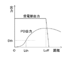
図3は、内視鏡側コネクタ17とプロセッサ側コネクタ60との間の距離に応じた給電部62に対する受電部36の距離を横軸にとり、給電部62から受電した受電部36が出力する出力電圧と、PD42により検出される検出信号の電圧(漏れ光の大きさ)とを縦軸にとって例示したものである。なお、内視鏡側コネクタ17がプロセッサ側コネクタ60に装着されているときの給電部62に対する受電部36の距離、即ち、接続時距離を0としている。
FIG. 3 shows the output of the
これによれば、内視鏡側コネクタ17がプロセッサ側コネクタ60から取り外されるときに、給電部62に対する受電部36の距離が0からLoffまで増加しても、受電部36は給電部62に対して受電可能な距離にあり、電源生成部32及び電源制御部34が駆動されている状態にある。
According to this, when the
一方、給電部62に対する受電部36の距離がLoffを超えると受電部36の出力電圧が急激に減少して電源生成部32及び電源制御部34の動作が電力の不足により停止した状態となる。
On the other hand, when the distance of the
これに対して、PD42の検出信号の電圧(漏れ光の大きさ)は、給電部62に対する受電部36の距離が0から増加するにつれて徐々に大きくなる。
On the other hand, the voltage of the detection signal of the PD 42 (the magnitude of leakage light) gradually increases as the distance of the
したがって、PD42によりこのような漏れ光が検出される場合、電源制御部34は、給電部62に対する受電部36の距離がLoffよりも少なくとも小さい閾値LthとなるときのPD42の検出信号の電圧Dthを閾値として、PD42の検出信号の電圧がDthより小さい値から閾値Dthの値まで増加したことを検出したときに、内視鏡側コネクタ17とプロセッサ側コネクタ60との間の距離の増加を検出したものと判断する。
Therefore, when such leakage light is detected by the
そして、この検出の直後において、電源生成部32の各電源Vdd1、Vdd2、Vdd3から固体撮像素子30への電源供給を規定の順序で停止させることで、受電部36が給電部62に対して受電不能な距離となる前に、即ち、自身の動作が電力の低下により停止する前に、固体撮像素子30の駆動を適切に停止させることができる。
Immediately after this detection, the
なお、PD42の検出信号の電圧(漏れ光の大きさ)は、PD42の設置位置等の設置形態によっては、図4に示すように給電部62に対する受電部36の距離が0から増加するにつれて徐々に小さくなる場合もある。
The voltage of the detection signal of the PD 42 (the magnitude of leakage light) gradually increases as the distance of the
PD42によりこのような漏れ光が検出される場合、電源制御部34は、給電部62に対する受電部36の距離がLoffよりも少なくとも小さい閾値LthとなるときのPD42の検出信号の電圧Dthを閾値として、PD42の検出信号の電圧がDthより大きい値から閾値Dthの値まで減少したことを検出したときに、内視鏡側コネクタ17とプロセッサ側コネクタ60との間の距離の増加を検出したものと判断する。そして、この検出の直後において上述の同様にして固体撮像素子30の駆動を停止させる。
When such leakage light is detected by the
図5は、固体撮像素子の破損防止機能に関する電源制御部34の処理手順を示したフローチャートである。なお、電源生成部32の各電源Vdd1、Vdd2、Vdd3から固体撮像素子30への電源供給の停止は、電源Vdd3、電源Vdd2、電源Vdd1の順序で行うことが規定されているものとする。
FIG. 5 is a flowchart showing a processing procedure of the power
電源制御部34は、電源生成部32の各電源Vdd1、Vdd2、Vdd3から固体撮像素子30への電源供給が行われて固体撮像素子30が駆動されている状態において、図5のフローチャートに示す処理を繰り返し実行する。
The power
電源制御部34は、まず、PD42から漏れ光の大きさを示す検出信号を取得する(ステップS10)。そして、取得した検出信号に基づいて内視鏡側コネクタ17とプロセッサ側コネクタ60との間の距離が増加したか否かを判定する(ステップS12)。NOと判断した場合には、本処理を終了する。
First, the power
一方、ステップS12においてYESと判定した場合には、続いて電源生成部32の電源Vdd3から固体撮像素子30への電源供給を停止させる(ステップS14)。
On the other hand, when it determines with YES in step S12, the power supply from the power supply Vdd3 of the power generation part 32 to the solid-
次に、電源生成部32の電源Vdd2から固体撮像素子30への電源供給を停止させる(ステップS16)。
Next, the power supply from the power supply Vdd2 of the power generation unit 32 to the solid-
そして次に、電源生成部32の電源Vdd1から固体撮像素子30への電源供給を停止させる(ステップS18)。これによって、固体撮像素子30の駆動が安全に停止する。最後に自身の動作を停止させる(ステップS20)。
Next, power supply from the power supply Vdd1 of the power generation unit 32 to the solid-
次に、図6は、距離情報検出手段の具体的な形態が相違する第1〜第3の実施の形態の内視鏡システム2のうちの第2の実施の形態の内視鏡システム2を示したものであり、図2と同一又は類似作用の構成要素には同一符号を付し、説明を省略する。 Next, FIG. 6 shows the endoscope system 2 according to the second embodiment among the endoscope systems 2 according to the first to third embodiments in which the specific form of the distance information detecting means is different. The components having the same or similar functions as those in FIG. 2 are denoted by the same reference numerals, and the description thereof is omitted.
図6に示すように内視鏡10は、距離情報検出手段として第1の実施の形態のPD42の代わりにスイッチ44を有する。
As shown in FIG. 6, the
スイッチ44は、例えば物理的なスイッチであり、内視鏡側コネクタ17がプロセッサ側コネクタ60に装着(接続)されたときにオンとなり、内視鏡側コネクタ17がプロセッサ側コネクタ60から取り外されるときにオフに切り替わる。
The
例えば、スイッチ44は内視鏡側コネクタ17の端面から突出する押下部材を有し、内視鏡側コネクタ17がプロセッサ側コネクタ60に装着されると、その押下部材がプロセッサ側コネクタ60の端面により押下されてオフからオンに切り替わるものとすることができる。
For example, the
このスイッチ44はオンのときにはオン状態を示す状態信号(本実施の形態ではハイレベル信号)を出力し、オフのときにはオフ状態を示す状態信号(本実施の形態ではローレベル信号)を出力し、それらの状態信号を距離情報として電源制御部34に与える。
When this
なお、スイッチ44の状態信号は、内視鏡側コネクタ17とプロセッサ側コネクタ60との間の距離によって変化するものであり、内視鏡側コネクタ17とプロセッサ側コネクタ60との間の距離に関する距離情報に相当し、かつ、上述のように給電部62に対する受電部36の距離に関する距離情報にも相当する。
The state signal of the
また、スイッチ44から出力される状態信号がどのような形態であってもよく、本明細書では、その形態がどのような場合であっても、内視鏡側コネクタ17がプロセッサ側コネクタ60に装着されたときのスイッチ44の状態をオン、内視鏡側コネクタ17がプロセッサ側コネクタ60から取り外されたときのスイッチ44の状態をオフというものとする。
Further, the state signal output from the
電源制御部34は、固体撮像素子30が駆動されている状態において、即ち、電源生成部32の各電源Vdd1、Vdd2、Vdd3から固体撮像素子30への電源供給が行われている状態において、スイッチ44の状態信号に基づいて、内視鏡側コネクタ17とプロセッサ側コネクタ60との間の距離が増加したか否かを検出する。そして、この増加を検出した場合には、内視鏡側コネクタ17がプロセッサ側コネクタ60から取り外されることを検出したものとして、第1の実施の形態と同様に、電源生成部32の各電源Vdd1、Vdd2、Vdd3から固体撮像素子30への電源供給を規定の順序で停止させる。
The power
図7は、内視鏡側コネクタ17とプロセッサ側コネクタ60との間の距離に応じた給電部62に対する受電部36の距離を横軸にとり、給電部62から受電した受電部36が出力する出力電圧と、スイッチ44の状態信号の電圧とを縦軸にとって例示したものである。なお、給電部62から受電した受電部36が出力する出力電圧に関しては図3において説明した通りであるから、ここでは説明を省略する。
FIG. 7 shows the output of the
これによれば、スイッチ44の状態信号の電圧は、給電部62に対する受電部36の距離が0から増加し、距離がLoffよりも少なくとも小さい閾値Lthとなったときにオン状態を示すハイレベル値からオフ状態を示すローレベル値に変化する。
According to this, the voltage of the state signal of the
したがって、電源制御部34は、スイッチ44の状態信号の電圧がハイレベル値よりも小さい閾値Dth以下の値になったことを検出したときに、スイッチ44のオンからオフへの切り替わりを検出したものとし、内視鏡側コネクタ17とプロセッサ側コネクタ60との間の距離の増加を検出したものと判断する。
Accordingly, when the power
そして、この検出の直後において、第1の実施の形態と同様に電源生成部32の各電源Vdd1、Vdd2、Vdd3から固体撮像素子30への電源供給を規定の順序で停止させることで、受電部36が給電部62に対して受電不能な距離となる前に、即ち、自身の動作が電力の低下により停止する前に、固体撮像素子30の駆動を適切に停止させることができる。
Immediately after this detection, as in the first embodiment, the power supply unit 32 stops the power supply from the respective power supplies Vdd1, Vdd2, and Vdd3 to the solid-
なお、スイッチ44の状態信号が図7とは逆にオン状態ではローレベル信号、オフ状態ではハイレベル信号である場合であってもスイッチ44のオンからオフへの切り替わりを同様に検出して、内視鏡側コネクタ17がプロセッサ側コネクタ60から取り外されることを検出したものとすればよい。
In addition, even when the state signal of the
また、第2の実施の形態における固体撮像素子30の破損防止機能に関する電源制御部34の処理手順については図5に示した第1の実施の形態のものと同様であるから説明は省略する。
Further, the processing procedure of the power
次に、図8は、距離情報検出手段の具体的な形態が相違する第1〜第3の実施の形態の内視鏡システム2のうちの第3の実施の形態の内視鏡システム2を示したものであり、図2と同一又は類似作用の構成要素には同一符号を付し、説明を省略する。 Next, FIG. 8 shows the endoscope system 2 according to the third embodiment among the endoscope systems 2 according to the first to third embodiments in which specific forms of the distance information detecting means are different. The components having the same or similar functions as those in FIG. 2 are denoted by the same reference numerals, and the description thereof is omitted.
図8に示すように内視鏡10は、距離情報検出手段として第1の実施の形態のPD42の代わりに位置検知用コイル48を有する。
As shown in FIG. 8, the
位置検知用コイル48は、給電部62の1次コイルと磁気結合可能なコイルであって、内視鏡側コネクタ17がプロセッサ装置11のプロセッサ側コネクタ60に装着された状態において、給電部62の1次コイルと磁気結合可能な距離に近接して配置される。
The
そして、この位置検知用コイル48は、給電部62(1次コイル)に対する距離に応じた電圧の検出信号を距離情報として電源制御部34に与える。
The
なお、位置検知用コイル48の検出信号は、内視鏡側コネクタ17とプロセッサ側コネクタ60との間の距離によって変化するため、内視鏡側コネクタ17とプロセッサ側コネクタ60との間の距離に関する距離情報に相当し、かつ、上述のように給電部62に対する受電部36の距離に関する距離情報にも相当する。
Since the detection signal of the
電源制御部34は、固体撮像素子30が駆動されている状態において、即ち、電源生成部32の各電源Vdd1、Vdd2、Vdd3から固体撮像素子30への電源供給が行われている状態において、位置検知用コイル48の検出信号に基づいて、内視鏡側コネクタ17とプロセッサ側コネクタ60との間の距離が増加したか否かを検出する。そして、この増加を検出した場合には、内視鏡側コネクタ17がプロセッサ側コネクタ60から取り外されることを検出したものとして、第1の実施の形態と同様に、電源生成部32の各電源Vdd1、Vdd2、Vdd3から固体撮像素子30への電源供給を規定の順序で停止させる。
The
図9は、内視鏡側コネクタ17とプロセッサ側コネクタ60との間の距離に応じた給電部62に対する受電部36の距離を横軸にとり、給電部62から受電した受電部36が出力する出力電圧と、位置検知用コイル48の検出信号の電圧とを縦軸にとって例示したものである。なお、給電部62から受電した受電部36が出力する出力電圧に関しては図3において説明した通りであるから、ここでは説明を省略する。
FIG. 9 shows the output of the
同図に示すように位置検知用コイル48は、給電部62に対する受電部36の距離が距離Loffよりも小さい距離において、その検出信号の電圧が徐々に小さくなるもの、または、受電不能な距離となるものとする。
As shown in the figure, the
したがって、電源制御部34は、給電部62に対する受電部36の距離がLoffよりも少なくとも小さい閾値Lthとなったときの位置検知用コイル48の検出信号の電圧Dthを閾値として、位置検知用コイル48の検出信号の値がDthより大きい値から閾値Dthの値まで減少したことを検出したときに、内視鏡側コネクタ17とプロセッサ側コネクタ60との間の距離の増加を検出したものと判断する。
Therefore, the power
そして、この検出の直後において、第1の実施の形態と同様に電源生成部32の各電源Vdd1、Vdd2、Vdd3から固体撮像素子30への電源供給を規定の順序で停止させることで、受電部36が給電部62に対して受電不能な距離となる前に、即ち、自身の動作が電力の低下により停止する前に、固体撮像素子30の駆動を適切に停止させることができる。
Immediately after this detection, as in the first embodiment, the power supply unit 32 stops the power supply from the respective power supplies Vdd1, Vdd2, and Vdd3 to the solid-
なお、第3の実施の形態における固体撮像素子30の破損防止機能に関する電源制御部34の処理手順については図5に示した第1の実施の形態のものと同様であるから説明は省略する。
Note that the processing procedure of the power
以上、第1〜第3の実施の形態は、給電部62に対する受電部36の距離の関する距離情報(内視鏡側コネクタ17とプロセッサ側コネクタ60との間の距離に関する情報)を検出する距離情報検出手段と、その距離情報に基づいて電源生成部32の各電源Vdd1、Vdd2、Vdd3から固体撮像素子30への電源供給を規定の順序で停止させる電源制御部34とを内視鏡10に搭載した場合の態様を示したものである。
As described above, in the first to third embodiments, the distance information (information regarding the distance between the
これに対して、例えば第1、第2の実施の形態と同様の距離情報検出手段を図10の第4の実施の形態の内視鏡システム2に示すようにプロセッサ装置11に搭載し(距離情報検出手段70)、その距離情報検出手段70により検出した距離情報をプロセッサ装置11の制御部64が取得し、非接触型通信手段52を通じて内視鏡10の電源制御部34に与えるようにしてもよい。
On the other hand, for example, distance information detection means similar to those of the first and second embodiments is mounted on the
また、電源制御部34が行う電源生成部32の制御は、プロセッサ装置11の制御部64が非接触型通信手段52を通じて電源生成部32に与える制御信号により行うことも可能であり、内視鏡10における電源制御部34を不要にすることもできる。
Further, the control of the power generation unit 32 performed by the
また、第1〜第4の実施の形態では、内視鏡10の内部回路とプロセッサ装置11の内部回路との間の各種信号の送受信を非接触型通信手段52により非接触(光結合)で行うものとしたが、必ずしも非接触で行うものでなくてもよく、内視鏡10の内部回路とプロセッサ装置11の内部回路との間がアイソレーションデバイスにより絶縁されたものでなくてもよい。即ち、プロセッサ装置11から内視鏡10へと電力を伝送する非接触電力供給手段50は、内視鏡10の内部回路とプロセッサ装置11の内部回路との間を絶縁する目的ではなく、内視鏡側コネクタ17がプロセッサ側コネクタ60から取り外される際に、固体撮像素子30への電力供給を適切に停止させるための時間として、プロセッサ装置11から内視鏡10への電力供給が停止しない時間を確保する目的とするものであってもよい。
In the first to fourth embodiments, transmission / reception of various signals between the internal circuit of the
また、上記第1〜第4の実施の形態のように本発明は、内視鏡側コネクタ17がプロセッサ側コネクタ60から取り外される際の固体撮像素子30の駆動の停止の制御において、充電池やバックアップ電源としてのコンデンサ等の蓄電手段を必要としないため、内視鏡10は蓄電手段が非搭載の内視鏡とすることができる。したがって、蓄電手段の劣化によるメンテナンスの必要性を低減することができる。
In addition, as in the first to fourth embodiments, the present invention provides a rechargeable battery, a control device for controlling the driving of the solid-
また、図1に示した内視鏡システム2におけるプロセッサ装置11は、内視鏡先端部14の照明窓から出射する照明光を内視鏡10に供給する光源装置を内蔵するものであり、内視鏡10の内視鏡側コネクタ17とプロセッサ装置11のプロセッサ側コネクタ60は、図2、図6、図8、図10に示したように電力や電気信号を送受する電気コネクタとしての構成部以外にも、それらの図では省略した照明光をプロセッサ装置11から内視鏡10へと伝送するライトガイドコネクタとしての構成部も一体的に備える。
The
例えば、図11に示すように、内視鏡側コネクタ17には、内視鏡先端部14から連通するライトガイドが突出するライトガイド棒17Aが設けられる。このライトガイド棒17Aは、プロセッサ側コネクタ60に内視鏡側コネクタ17を装着した際に、プロセッサ側コネクタ60に設けられた開口60Aからプロセッサ装置11の内部へと挿入されて光源装置と光学的に接続される。
For example, as shown in FIG. 11, the
このような構成の内視鏡側コネクタ17及びプロセッサ側コネクタ60において、上述のように受電部36が給電部62に対して受電可能な距離から受電不能な距離へと切り替わる距離Loff(図3、4、7、9参照)、即ち、受電部36が給電部62に対して受電可能な最大距離Loffが、ライトガイド棒17Aの長さ(開口60Aからプロセッサ装置11の内部への挿入長)より短くなるような構成とすることは可能である。
In the
このとき、第1〜第3の実施の形態の内視鏡システム2において具体的に示したような距離情報検出手段により内視鏡側コネクタ17がプロセッサ側コネクタ60から取り外されるときの動作を検出した際に、光源装置からの照明光の出射を停止(発光自体の停止、又は、ライトガイド棒17Aへの光路を遮断)する形態とすると好適である。
At this time, the operation when the endoscope-
これによって、内視鏡側コネクタ17が取り外されたプロセッサ側コネクタ60の開口60Aから照明光が内視鏡10の外部に投射されることが防止される。
This prevents illumination light from being projected outside the
また、図1に示した内視鏡システム2のようにプロセッサ装置11が光源装置を内蔵するものではなく、図12に示すように内視鏡先端部14の照明窓から出射する照明光を供給する光源装置12がプロセッサ装置11とは別体の装置として構成されるものであってもよい。この場合に、内視鏡10のユニバーサルコード18の端部には、例えば、光源装置12に装着されるライトガイドコネクタ16が設けられ、そのライトガイドコネクタ16から延設された延長ケーブルを介してプロセッサ装置11に装着されるコネクタ17が設けられる。このときコネクタ17が上述の第1〜第4の実施の形態等に示した同一符号である内視鏡側コネクタ17に相当する。
Further, unlike the endoscope system 2 shown in FIG. 1, the
Vdd1,Vdd2,Vdd3…電源、2…内視鏡システム、10…電子内視鏡(内視鏡)、11…内視鏡用プロセッサ装置(プロセッサ装置)、12…光源装置、13…内視鏡挿入部(挿入部)、14…内視鏡先端部(先端部)、15…操作部、16…LGコネクタ、17…コネクタ(内視鏡側コネクタ)、18…ユニバーサルコード、19…モニタ、30…固体撮像素子、32…電源生成部、34…電源制御部、36…受電部、38,68…LED、40、66…PD、44…スイッチ、48…位置検知用コイル、50…非接触電力供給手段、52…非接触型通信手段、60…プロセッサ側コネクタ、60A…ガイド棒、62…給電部、64…制御部、70…距離情報検出手段、80…入力装置
Vdd1, Vdd2, Vdd3 ... power supply, 2 ... endoscope system, 10 ... electronic endoscope (endoscope), 11 ... processor device for processor (processor device), 12 ... light source device, 13 ... endoscope Insertion part (insertion part), 14 ... End of endoscope (tip), 15 ... Operation part, 16 ... LG connector, 17 ... Connector (endoscope side connector), 18 ... Universal cord, 19 ... Monitor, 30 DESCRIPTION OF SYMBOLS ... Solid-state image sensor 32 ... Power
Claims (13)
前記給電部に対する前記受電部の距離に関する距離情報を検出する距離情報検出手段と、
前記距離情報検出手段により検出された距離情報に基づいて、前記給電部に対して離間する方向への前記受電部の変位を検出すると、前記受電部が前記給電部に対して受電不能な距離となる前に前記電源生成部の複数の電源の各々から前記固体撮像素子への電力の供給を規定の順序で停止させる電源制御部と、
を備えた内視鏡システム。 From a power receiving unit that receives power in a non-contact manner from a power feeding unit, a power generation unit that generates a plurality of power sources having different voltages from the power received by the power receiving unit, and a plurality of power sources generated by the power generation unit An endoscope comprising: a solid-state imaging device driven by supplied power; and an endoscope processor device that includes the power feeding unit and is detachably connected to the endoscope. In the system,
Distance information detecting means for detecting distance information related to the distance of the power receiving unit with respect to the power feeding unit;
Based on the distance information detected by the distance information detection means, when detecting the displacement of the power receiving unit in a direction away from the power feeding unit, the power receiving unit is unable to receive power from the power feeding unit. A power control unit that stops the supply of power from each of the plurality of power sources of the power generation unit to the solid-state imaging device in a specified order before
Endoscope system equipped with.
前記電源制御部は、前記距離情報検出手段により検出された距離情報に基づいて、前記給電部に対する前記受電部の距離の前記接続時距離からの増加を検出した場合に、前記給電部に対して離間する方向への前記受電部の変位を検出したと判断する請求項1、2、又は3に記載の内視鏡システム。 The power receiving unit is installed at a position of a connection time distance capable of receiving power with respect to the power feeding unit in a state where the endoscope is connected to the endoscope processor device.
When the power supply control unit detects an increase in the distance of the power reception unit relative to the power supply unit from the connection distance based on the distance information detected by the distance information detection unit, the power supply control unit The endoscope system according to claim 1, 2, or 3, wherein it is determined that a displacement of the power reception unit in a separating direction is detected.
前記受電部は、前記内視鏡側コネクタが前記プロセッサ側コネクタに接続された状態において前記給電部に対して前記接続時距離の位置に設置され、かつ、前記内視鏡側コネクタが前記プロセッサ側コネクタから取り外されるときの前記内視鏡側コネクタと前記プロセッサ側コネクタとの間の距離の増加に伴って前記給電部に対する前記受電部の距離が前記接続時距離から増加し、
前記距離情報検出手段は、前記内視鏡側コネクタと前記プロセッサ側コネクタとの間の距離に関する情報を前記距離情報として検出する検出手段であり、
前記電源制御部は、前記内視鏡側コネクタが前記プロセッサ側コネクタに装着された状態において前記プロセッサ側コネクタから取り外されるときの前記内視鏡側コネクタと前記プロセッサ側コネクタとの間の距離の増加を、前記給電部に対する前記受電部の距離の前記接続時距離からの増加として検出する請求項4に記載の内視鏡システム。 The endoscope has an endoscope-side connector that is detachably connected to a processor-side connector of the endoscope processor device.
The power receiving unit is installed at the connection distance with respect to the power feeding unit in a state where the endoscope side connector is connected to the processor side connector, and the endoscope side connector is connected to the processor side With the increase in the distance between the endoscope side connector and the processor side connector when removed from the connector, the distance of the power reception unit relative to the power supply unit increases from the connection time distance,
The distance information detection means is detection means for detecting information on a distance between the endoscope side connector and the processor side connector as the distance information,
The power control unit increases a distance between the endoscope side connector and the processor side connector when the endoscope side connector is detached from the processor side connector in a state where the endoscope side connector is attached to the processor side connector. The endoscope system according to claim 4, wherein a distance of the power receiving unit with respect to the power feeding unit is detected as an increase from the connection distance.
前記内視鏡は、前記光信号を前記内視鏡側コネクタを通じて受信する通信用受光手段を有し、
前記距離情報検出手段は、前記通信用発光手段から送信された光信号の漏れ光の大きさを前記距離情報として検出する距離情報検出用受光手段であり、
前記電源制御部は、前記内視鏡側コネクタが前記プロセッサ側コネクタに接続された状態において前記プロセッサ側コネクタから取り外されるときの前記内視鏡側コネクタと前記プロセッサ側コネクタとの間の距離の増加を、前記漏れ光の増加又は減少により検出する請求項5に記載の内視鏡システム。 The endoscope processor device has a communication light emitting means for transmitting an optical signal for performing non-contact communication with the endoscope through the processor side connector,
The endoscope has a communication light receiving means for receiving the optical signal through the endoscope side connector,
The distance information detection means is a distance information detection light-receiving means for detecting, as the distance information, the magnitude of leakage light of the optical signal transmitted from the communication light-emitting means,
The power control unit increases a distance between the endoscope side connector and the processor side connector when the endoscope side connector is detached from the processor side connector in a state where the endoscope side connector is connected to the processor side connector. The endoscope system according to claim 5, which is detected by increasing or decreasing the leakage light.
前記電源制御部は、前記内視鏡側コネクタが前記プロセッサ側コネクタに接続された状態において前記プロセッサ側コネクタから取り外されるときの前記内視鏡側コネクタと前記プロセッサ側コネクタとの間の距離の増加を、前記スイッチのオンからオフへの切り替わりにより検出する請求項5に記載の内視鏡システム。 The distance information detecting means is a physical switch that is turned on when the endoscope side connector is connected to the processor side connector and turned off when the endoscope side connector is detached from the processor side connector. And
The power control unit increases a distance between the endoscope side connector and the processor side connector when the endoscope side connector is detached from the processor side connector in a state where the endoscope side connector is connected to the processor side connector. The endoscope system according to claim 5, which is detected by switching the switch from on to off.
前記距離情報検出手段は、前記給電部と磁気結合するコイルであり、
前記電源制御部は、前記内視鏡側コネクタが前記プロセッサ側コネクタに装着された状態において前記プロセッサ側コネクタから取り外されるときの前記内視鏡側コネクタと前記プロセッサ側コネクタとの間の距離の増加を、前記コイルの出力値の減少により検出する請求項5に記載の内視鏡システム。 The power receiving unit receives power by magnetic coupling with the power feeding unit,
The distance information detection means is a coil that is magnetically coupled to the power feeding unit,
The power control unit increases a distance between the endoscope side connector and the processor side connector when the endoscope side connector is detached from the processor side connector in a state where the endoscope side connector is attached to the processor side connector. The endoscope system according to claim 5, wherein the signal is detected by a decrease in the output value of the coil.
前記内視鏡側コネクタと前記プロセッサ側コネクタは、前記光源装置からの照明光を前記内視鏡に伝送するライトガイドコネクタを一体的に備えた請求項5から8のいずれか1項に記載の内視鏡システム。 The endoscope processor device includes a light source device that supplies illumination light to irradiate an observation site of the endoscope to the endoscope,
The said endoscope side connector and the said processor side connector were integrally provided with the light guide connector which transmits the illumination light from the said light source device to the said endoscope. Endoscope system.
前記受電部が前記給電部に対して受電可能な距離から受電不能な距離へと切り替わる距離は、前記ライトガイド棒の長さよりも短い請求項9に記載の内視鏡システム。 The endoscope-side connector has a light guide bar that is inserted into the endoscope processor device from an opening of the processor-side connector,
The endoscope system according to claim 9, wherein a distance at which the power receiving unit switches from a distance at which the power receiving unit can receive power to a distance at which power cannot be received is shorter than a length of the light guide rod.
Priority Applications (1)
| Application Number | Priority Date | Filing Date | Title |
|---|---|---|---|
| JP2014056824A JP6122802B2 (en) | 2014-03-19 | 2014-03-19 | Endoscope system and endoscope |
Applications Claiming Priority (1)
| Application Number | Priority Date | Filing Date | Title |
|---|---|---|---|
| JP2014056824A JP6122802B2 (en) | 2014-03-19 | 2014-03-19 | Endoscope system and endoscope |
Publications (2)
| Publication Number | Publication Date |
|---|---|
| JP2015177902A true JP2015177902A (en) | 2015-10-08 |
| JP6122802B2 JP6122802B2 (en) | 2017-04-26 |
Family
ID=54262412
Family Applications (1)
| Application Number | Title | Priority Date | Filing Date |
|---|---|---|---|
| JP2014056824A Active JP6122802B2 (en) | 2014-03-19 | 2014-03-19 | Endoscope system and endoscope |
Country Status (1)
| Country | Link |
|---|---|
| JP (1) | JP6122802B2 (en) |
Cited By (3)
| Publication number | Priority date | Publication date | Assignee | Title |
|---|---|---|---|---|
| WO2017122626A1 (en) * | 2016-01-12 | 2017-07-20 | オリンパス株式会社 | Endoscope device |
| JPWO2018230068A1 (en) * | 2017-06-12 | 2019-06-27 | オリンパス株式会社 | Endoscope device |
| JPWO2020250393A1 (en) * | 2019-06-13 | 2020-12-17 |
Citations (8)
| Publication number | Priority date | Publication date | Assignee | Title |
|---|---|---|---|---|
| JPH04131202U (en) * | 1991-05-21 | 1992-12-02 | 日立電子株式会社 | Light source and control device for TV endoscopes |
| JPH07227377A (en) * | 1994-02-17 | 1995-08-29 | Machida Endscope Co Ltd | Controlling apparatus for semiconductor |
| JPH07326427A (en) * | 1995-06-05 | 1995-12-12 | Olympus Optical Co Ltd | Electric connector |
| JPH10151113A (en) * | 1996-11-26 | 1998-06-09 | Asahi Optical Co Ltd | Connector device for electronic endoscope device |
| JPH10155740A (en) * | 1996-12-04 | 1998-06-16 | Fuji Photo Optical Co Ltd | Electronic endoscope apparatus |
| JP2004159833A (en) * | 2002-11-12 | 2004-06-10 | Fuji Photo Optical Co Ltd | Electronic endoscopic apparatus |
| JP2009189528A (en) * | 2008-02-14 | 2009-08-27 | Fujinon Corp | Processor unit for endoscope and endoscopic system |
| JP2009189529A (en) * | 2008-02-14 | 2009-08-27 | Fujinon Corp | Processor unit for endoscope |
-
2014
- 2014-03-19 JP JP2014056824A patent/JP6122802B2/en active Active
Patent Citations (8)
| Publication number | Priority date | Publication date | Assignee | Title |
|---|---|---|---|---|
| JPH04131202U (en) * | 1991-05-21 | 1992-12-02 | 日立電子株式会社 | Light source and control device for TV endoscopes |
| JPH07227377A (en) * | 1994-02-17 | 1995-08-29 | Machida Endscope Co Ltd | Controlling apparatus for semiconductor |
| JPH07326427A (en) * | 1995-06-05 | 1995-12-12 | Olympus Optical Co Ltd | Electric connector |
| JPH10151113A (en) * | 1996-11-26 | 1998-06-09 | Asahi Optical Co Ltd | Connector device for electronic endoscope device |
| JPH10155740A (en) * | 1996-12-04 | 1998-06-16 | Fuji Photo Optical Co Ltd | Electronic endoscope apparatus |
| JP2004159833A (en) * | 2002-11-12 | 2004-06-10 | Fuji Photo Optical Co Ltd | Electronic endoscopic apparatus |
| JP2009189528A (en) * | 2008-02-14 | 2009-08-27 | Fujinon Corp | Processor unit for endoscope and endoscopic system |
| JP2009189529A (en) * | 2008-02-14 | 2009-08-27 | Fujinon Corp | Processor unit for endoscope |
Cited By (5)
| Publication number | Priority date | Publication date | Assignee | Title |
|---|---|---|---|---|
| WO2017122626A1 (en) * | 2016-01-12 | 2017-07-20 | オリンパス株式会社 | Endoscope device |
| JPWO2018230068A1 (en) * | 2017-06-12 | 2019-06-27 | オリンパス株式会社 | Endoscope device |
| JPWO2020250393A1 (en) * | 2019-06-13 | 2020-12-17 | ||
| WO2020250393A1 (en) * | 2019-06-13 | 2020-12-17 | オリンパス株式会社 | Plug, connector, and endoscope device |
| JP7190037B2 (en) | 2019-06-13 | 2022-12-14 | オリンパス株式会社 | Plugs, connectors, endoscopic devices and endoscopes |
Also Published As
| Publication number | Publication date |
|---|---|
| JP6122802B2 (en) | 2017-04-26 |
Similar Documents
| Publication | Publication Date | Title |
|---|---|---|
| US10058239B2 (en) | Endoscope system | |
| JP6348854B2 (en) | Endoscope processor device, endoscope system, and non-contact power feeding method for endoscope system | |
| JP2006217317A (en) | Damage prevention system for charge coupled device | |
| US10463231B2 (en) | Endoscope | |
| US10856732B2 (en) | Endoscope system with processor side connector | |
| EP3123923B1 (en) | Electronic endoscope apparatus | |
| US10433711B2 (en) | Connector and endoscope system | |
| JP6122802B2 (en) | Endoscope system and endoscope | |
| US20210113059A1 (en) | Endoscope apparatus, method of controlling endoscope apparatus and non-transitory computer readable recording medium recording program for controlling endoscope apparatus | |
| US10327623B2 (en) | Endoscope connector, endoscope, and endoscope system | |
| US10756574B2 (en) | Medical tool | |
| JP4789520B2 (en) | Endoscope processor and endoscope system | |
| JP2006320381A (en) | Electronic endoscopic apparatus | |
| JP2006212248A (en) | Damage prevention system for ccd | |
| US8562514B2 (en) | Medical apparatus and endoscope system with memory function | |
| JP2009201543A (en) | Endoscope system | |
| JP4303053B2 (en) | Capsule endoscope guidance system | |
| WO2018230068A1 (en) | Endoscope device | |
| JP6374278B2 (en) | Endoscope system | |
| JP5032174B2 (en) | Endoscope device | |
| US9195045B2 (en) | Endoscope apparatus having first and second light sources and control section which controls the first light and second light sources according to a detected type of attached adapter | |
| JP6960470B2 (en) | Endoscopy inspection system, endoscopy inspection equipment, endoscopy method | |
| WO2018230067A1 (en) | Endoscope apparatus and endoscope system | |
| JP2020185106A (en) | Processor and endoscope system | |
| JP2021023538A (en) | Endoscope system |
Legal Events
| Date | Code | Title | Description |
|---|---|---|---|
| A621 | Written request for application examination |
Free format text: JAPANESE INTERMEDIATE CODE: A621 Effective date: 20160310 |
|
| A131 | Notification of reasons for refusal |
Free format text: JAPANESE INTERMEDIATE CODE: A131 Effective date: 20161222 |
|
| A977 | Report on retrieval |
Free format text: JAPANESE INTERMEDIATE CODE: A971007 Effective date: 20161221 |
|
| A521 | Request for written amendment filed |
Free format text: JAPANESE INTERMEDIATE CODE: A523 Effective date: 20170210 |
|
| TRDD | Decision of grant or rejection written | ||
| A01 | Written decision to grant a patent or to grant a registration (utility model) |
Free format text: JAPANESE INTERMEDIATE CODE: A01 Effective date: 20170323 |
|
| A61 | First payment of annual fees (during grant procedure) |
Free format text: JAPANESE INTERMEDIATE CODE: A61 Effective date: 20170403 |
|
| R150 | Certificate of patent or registration of utility model |
Ref document number: 6122802 Country of ref document: JP Free format text: JAPANESE INTERMEDIATE CODE: R150 |
|
| R250 | Receipt of annual fees |
Free format text: JAPANESE INTERMEDIATE CODE: R250 |
|
| R250 | Receipt of annual fees |
Free format text: JAPANESE INTERMEDIATE CODE: R250 |
|
| R250 | Receipt of annual fees |
Free format text: JAPANESE INTERMEDIATE CODE: R250 |
|
| R250 | Receipt of annual fees |
Free format text: JAPANESE INTERMEDIATE CODE: R250 |
|
| R250 | Receipt of annual fees |
Free format text: JAPANESE INTERMEDIATE CODE: R250 |