JP2015161069A - Gateway blockage arrangement for parking space, and method thereof - Google Patents

Gateway blockage arrangement for parking space, and method thereof Download PDF

Info

Publication number
JP2015161069A
JP2015161069A JP2014035066A JP2014035066A JP2015161069A JP 2015161069 A JP2015161069 A JP 2015161069A JP 2014035066 A JP2014035066 A JP 2014035066A JP 2014035066 A JP2014035066 A JP 2014035066A JP 2015161069 A JP2015161069 A JP 2015161069A
Authority
JP
Japan
Prior art keywords
blocking
entrance
exit
parking space
state
Prior art date
Legal status (The legal status is an assumption and is not a legal conclusion. Google has not performed a legal analysis and makes no representation as to the accuracy of the status listed.)
Granted
Application number
JP2014035066A
Other languages
Japanese (ja)
Other versions
JP6349105B2 (en
Inventor
耕造 岡田
Kozo Okada
耕造 岡田
聡 猪俣
Satoshi Inomata
聡 猪俣
裕輔 阿部
Hirosuke Abe
裕輔 阿部
展之 菅谷
Nobuyuki Sugaya
展之 菅谷
Current Assignee (The listed assignees may be inaccurate. Google has not performed a legal analysis and makes no representation or warranty as to the accuracy of the list.)
Bunka Shutter Co Ltd
Original Assignee
Bunka Shutter Co Ltd
Priority date (The priority date is an assumption and is not a legal conclusion. Google has not performed a legal analysis and makes no representation as to the accuracy of the date listed.)
Filing date
Publication date
Application filed by Bunka Shutter Co Ltd filed Critical Bunka Shutter Co Ltd
Priority to JP2014035066A priority Critical patent/JP6349105B2/en
Publication of JP2015161069A publication Critical patent/JP2015161069A/en
Application granted granted Critical
Publication of JP6349105B2 publication Critical patent/JP6349105B2/en
Active legal-status Critical Current
Anticipated expiration legal-status Critical

Links

Images

Landscapes

  • Refuge Islands, Traffic Blockers, Or Guard Fence (AREA)

Abstract

PROBLEM TO BE SOLVED: To provide a gateway blockage arrangement for a parking space and a method thereof, capable of facilitating installation work.SOLUTION: A gateway blockage arrangement includes: a blockage member 11 for blocking a gateway 4 of a garage 3 as a parking space; and a winding shaft (not shown) which is stored inside a case member 9, constituting a lift means for lifting up and down the blockage member 11. The blockage member 11 is structured including: a laterally length member 13; and a string member 12 which is a member to be fed from the winding shaft and be wound, a bottom part of which is connected to an upper face 13A of the lateral length member 13, and an upper end part of which is connected to the winding shaft. The gateway blockage arrangement is disposed above the ground 5 as a parking area in the garage 3.

Description

本発明は、自動車、自動二輪車、自転車(原動機付自転車を含む)等の各種の車両を駐車するための駐車スペースの出入口遮断装置及びその方法に係り、例えば、住宅の内部や敷地に設置された車庫(ガレージ)、公共の有料駐車場(月極駐車場、コインパーキング等の契約駐車場)等の各種の駐車スペースの出入口遮断装置に利用できるものである。   The present invention relates to a parking space entrance / exit blocking device for parking various vehicles such as automobiles, motorcycles, and bicycles (including motorbikes), and a method thereof, for example, installed in a house or on a site. It can be used as an entrance / exit blocking device for various parking spaces such as a garage and a public pay parking lot (monthly parking lot, contract parking lot such as coin parking).

従来より、車両を駐車するための駐車スペースの出入口には、下記の特許文献1,2に示されているように、駐車スペースへの車両や人の侵入を遮断するための遮断体と、この遮断体を昇降させるための昇降手段とを備えている出入口遮断装置が設置されている。   Conventionally, at the entrance of a parking space for parking a vehicle, as shown in Patent Documents 1 and 2 below, a blocking body for blocking the entry of a vehicle or a person into the parking space, and this An entrance / exit shut-off device provided with lifting means for lifting and lowering the blocking body is installed.

下記の特許文献1,2に示されている出入口遮断装置では、柱状部材を含んで構成されている遮断体は、出入口を遮断させる必要のないときには、地中の収納スペースに収納されており、出入口を遮断させる必要が生じたときには、上記収納スペースにおける遮断体の下方に配置されている昇降手段である駆動装置により上昇するものとなっている。   In the entrance / exit shut-off devices shown in the following Patent Documents 1 and 2, the shut-off body configured to include the columnar member is stored in the underground storage space when it is not necessary to block the entrance / exit, When it is necessary to block the entrance / exit, the drive unit is lifted by a lifting / lowering unit disposed below the blocking body in the storage space.

特開平8−49222号公報JP-A-8-49222 特開2002−227516号公報JP 2002-227516 A

ところで、上述した従来の駐車スペースの出入口遮断装置では、遮断体及びこの遮断体を昇降させるための昇降手段を地中に埋設させなければならないため、この出入口遮断装置の設置作業は、手間やコストが掛かかるものであった。   By the way, in the conventional entrance / exit blocking device for a parking space described above, since the blocking body and the raising / lowering means for raising and lowering the blocking body have to be buried in the ground, the installation work of the entrance / exit blocking device is laborious and costly. It took a long time.

このため、出入口遮断装置の設置作業をより簡単にするための工夫が求められている。   For this reason, the device for making installation work of an entrance-exit blocker easier is calculated | required.

本発明の目的は、設置作業がより簡単に行えるようになる駐車スペースの出入口遮断装置及びその方法を提供するところにある。   An object of the present invention is to provide a parking space entrance / exit blocking device and a method thereof that make installation work easier.

本発明に係る駐車スペースの出入口遮断装置は、駐車スペースの出入口を遮断するための昇降自在な遮断体と、この遮断体を昇降させるための昇降手段と、を備えている駐車スペースの出入口遮断装置において、前記駐車スペースの駐車面の上方に配置されていることを特徴とするものである。   An entrance / exit blocking device for a parking space according to the present invention includes an exit block that can be raised and lowered for blocking an entrance / exit of the parking space, and an elevating means for raising and lowering the block body. In the above, it is arrange | positioned above the parking surface of the said parking space.

本発明では、駐車スペースの出入口遮断装置は、駐車スペースの駐車面の下方ではなく、駐車面の上方に配置されている。   In the present invention, the parking space entrance / exit blocking device is disposed above the parking surface, not below the parking surface of the parking space.

すなわち、本発明では、駐車スペースの出入口遮断装置を従来のように駐車面の下方に埋設する作業が必要ない。   That is, in the present invention, there is no need to embed a parking space entrance / exit blocking device under the parking surface as in the prior art.

このため、本発明によると、駐車スペースの出入口遮断装置の設置作業がより簡単に行えるようになる。   For this reason, according to this invention, the installation operation | work of the entrance-and-exit interruption | blocking apparatus of a parking space can be performed more easily.

本発明において、遮断体を昇降させるための昇降手段の形式、構造は、任意なものでよく、昇降手段の一例は、巻取軸を有するものである。   In the present invention, the form and structure of the lifting means for lifting and lowering the blocking body may be arbitrary, and an example of the lifting means has a winding shaft.

本発明において、遮断体の形式、構造も任意なものでよい。昇降手段が上述したように巻取軸を有するものである場合の遮断体の一例は、巻取軸によって繰り出され、巻き取られる被巻取部材と、この被巻取部材の下部に配置された横長部材とを含んで構成されているものである。   In the present invention, the type and structure of the blocking body may be arbitrary. An example of the blocking body in the case where the elevating means has the winding shaft as described above is a member to be wound that is fed and wound by the winding shaft, and disposed at the lower part of the member to be wound. It is comprised including a horizontally long member.

ここで、横長部材とは、横方向(昇降方向と直交する方向である左右方向)に長い部材であり、例えば、棒状部材(中空のものでもよく、中実のものでもよい)でもよく、板状部材(言い換えると、パネル状部材)等でもよく。また、横長部材は、被巻取部材の下部に1個配置するようにしてもよく、昇降方向に複数個配置するようにしてもよい。   Here, the laterally long member is a member that is long in the lateral direction (left and right direction that is a direction orthogonal to the ascending / descending direction), for example, a rod-shaped member (which may be hollow or solid), A shaped member (in other words, a panel shaped member) or the like may be used. Further, one horizontally long member may be arranged below the member to be wound, or a plurality of horizontally long members may be arranged in the ascending / descending direction.

本発明において、昇降手段を上述したように巻取軸を有するものとした場合には、遮断体による出入口の遮断状態を保持するための遮断状態保持手段を備えるようにしてもよく、しなくてもよい。   In the present invention, when the lifting / lowering means has the winding shaft as described above, it may be provided with blocking state holding means for holding the blocking state of the entrance / exit by the blocking body. Also good.

前者の場合によると、遮断体による出入口の遮断状態がより確実に保持されるようになる。   According to the former case, the shut-off state of the entrance / exit by the shut-off body is more reliably maintained.

本発明において、前述したように、昇降手段が、巻取軸を有するものであって、遮断体が、巻取軸によって繰り出され、巻き取られる被巻取部材と、この被巻取部材の下部に配置された横長部材とを含んで構成されているものである場合において、被巻取部材の形式、構造は、巻取軸によって繰り出され、巻き取られるものであれば任意なものでよい。   In the present invention, as described above, the elevating means has a take-up shaft, and the shield is drawn out and taken up by the take-up shaft, and a lower portion of the take-up member. In this case, the form and structure of the member to be wound may be arbitrary as long as they are fed out and wound by the winding shaft.

被巻取部材の第1の例は、紐状部材である。この第1の例では、被巻取部材は、1本の紐状部材で構成されるものでもよく、複数本の紐状部材で構成されるものでもよい。   A first example of the member to be wound is a string-like member. In this first example, the member to be wound may be constituted by one string-like member or may be constituted by a plurality of string-like members.

後者の場合には、これらの紐状部材のそれぞれを出入口の幅方向に離間して配置するとともに、これらの紐状部材のそれぞれを巻取軸から横長部材まで上下方向に延ばすようにしてもよい。   In the latter case, each of these string-like members may be arranged apart from each other in the width direction of the doorway, and each of these string-like members may be extended in the vertical direction from the winding shaft to the horizontally long member. .

これによると、複数個の紐状部材が巻取軸に巻き取られるとき、これらの紐状部材は、互いに巻取軸にこの巻取軸の径方向に重ならずに巻き取られるようになる。   According to this, when a plurality of string-like members are wound on the take-up shaft, these string-like members are wound on the take-up shaft without overlapping with each other in the radial direction of the take-up shaft. .

また、後者の場合(複数本の紐状部材で構成されるものである場合)には、それぞれの紐状部材の上端部の配置位置と下端部の配置位置は、前記巻取軸の軸方向にずれるようにしてもよい。   Moreover, in the latter case (in the case of being composed of a plurality of string-like members), the arrangement position of the upper end portion and the arrangement position of the lower end portion of each string-like member is the axial direction of the winding shaft. You may make it slip to.

これによると、複数本の紐状部材が巻取軸に巻き取られるとき、これらの紐状部材が、巻取軸にこの巻取軸の径方向に重ならずに螺旋状に巻き取られるようにすることができる。   According to this, when a plurality of string-like members are wound around the take-up shaft, these string-like members are wound up spirally around the take-up shaft without overlapping in the radial direction of the take-up shaft. Can be.

このため、複数本の紐状部材が巻取軸に巻き取られるとき、これらの紐状部材の巻き径を小さいものとすることができる。   For this reason, when a plurality of string-like members are wound on the take-up shaft, the winding diameter of these string-like members can be made small.

また、上述した被巻取部材の第2の例は、シート状部材である。ここで、シート状部材は1枚で構成されるものでもよく、複数枚で構成されるものでもよい。   Moreover, the 2nd example of the to-be-winded member mentioned above is a sheet-like member. Here, the sheet-like member may be composed of a single sheet or a plurality of sheets.

後者の場合には、それぞれのシート状部材を出入口の幅方向に離間して配置するようにしてもよく、それぞれのシート状部材同士を出入口の幅方向に縫着、接着、溶着するようにしてもよい。   In the latter case, the respective sheet-like members may be arranged apart from each other in the width direction of the doorway, and the respective sheet-like members are sewn, bonded, and welded in the width direction of the doorway. Also good.

なお、シート状部材は、防水性、耐久性を有する材料で形成することが好ましい。   In addition, it is preferable to form a sheet-like member with the material which has waterproofness and durability.

なお、シート状部材には、網目状のものも含む。   The sheet-like member includes a mesh-like member.

本発明において、遮断体が、前述したように、巻取軸によって繰り出され、巻き取られる被巻取部材と、この被巻取部材の下部に配置された横長部材とを含んで構成されているものである場合において、出入口が遮断体により遮断された状態における横長部材の高さ位置は、駐車スペースへの車両又は人の侵入の妨げとなる高さ位置となっていることが好ましい。   In the present invention, as described above, the blocking body is configured to include a member to be wound that is drawn out and wound by the winding shaft, and a horizontally long member that is disposed below the member to be wound. In the case of a thing, it is preferable that the height position of the horizontally long member in a state where the doorway is blocked by the blocking body is a height position that hinders entry of a vehicle or a person into the parking space.

本発明において、前述したように、遮断体による出入口の遮断状態を保持するための遮断状態保持手段を備えるようにした場合において、この遮断状態保持手段の形式、構造は任意なものでよい。   In the present invention, as described above, when the blocking state holding means for holding the blocking state of the entrance / exit by the blocking body is provided, the type and structure of the blocking state holding means may be arbitrary.

遮断状態保持手段は、例えば、連結部材により横長部材に連結された係止部材と、駐車面に設けられ、係止部材が係止する被係止部材と、を含んで構成されているものであってもよく、駐車面に設けられた係止部材と、連結部材により横長部材に連結され、係止部材が係止する被係止部材と、を含んで構成されているものであってもよい。   The blocking state holding means includes, for example, a locking member connected to the horizontally long member by a connecting member, and a locked member provided on the parking surface and locked by the locking member. It may be configured to include a locking member provided on the parking surface, and a locked member that is connected to the horizontally long member by the connecting member and is locked by the locking member. Good.

ここで、係止部材と被係止部材の第1の例は、係止部材と被係止部材のうちの一方は、磁石を含んで構成され、他方は、磁石に吸着する磁性体を含んで構成されているものである。また、係止部材と被係止部材の第2の例は、係止部材と被係止部材のうちの一方は、フック部材であり、他方は、フック部材が係止可能なピン部材又はリング部材等である。   Here, in the first example of the locking member and the locked member, one of the locking member and the locked member includes a magnet, and the other includes a magnetic body that is attracted to the magnet. It is composed of. Further, in the second example of the locking member and the locked member, one of the locking member and the locked member is a hook member, and the other is a pin member or ring that can be locked by the hook member. Member.

本発明において、昇降手段を前述したように巻取軸を有するものとした場合には、巻取軸の内部には、この巻取軸から被巻取部材が繰り出される際に、回転する巻取軸でばね力が蓄圧される戻しばねを配置し、この戻しばねのばね力を、常に遮断体の自重と同じ又はこれよりも大きくしてもよい。   In the present invention, when the lifting / lowering means has the winding shaft as described above, the winding shaft rotates inside the winding shaft when the member to be wound is unwound from the winding shaft. A return spring in which the spring force is accumulated on the shaft may be arranged, and the spring force of the return spring may always be equal to or greater than the dead weight of the blocking body.

戻しばねのばね力を常に遮断体の自重と同じにした場合、すなわち、戻しばねのばね力と遮断体の自重とが平衡状態となるようにした場合には、前述した遮断状態保持手段は必ずしも必要ではなくなり、また、出入口を遮断した状態の遮断体を上昇操作する力(持ち上げ操作する力)をより軽いものとすることができる。   When the spring force of the return spring is always the same as the weight of the blocking body, that is, when the spring force of the return spring and the weight of the blocking body are in an equilibrium state, the above-described blocking state holding means is not necessarily Further, it is not necessary, and the force for raising the blocking body in the state where the doorway is blocked (the force for lifting operation) can be made lighter.

また、戻しばねのばね力を常に遮断体の自重よりも大きくした場合には、遮断状態保持手段は必ず必要となるが、出入口を遮断した状態の遮断体を上昇操作する力(持ち上げ操作する力)は必要なく、遮断体は、蓄圧された戻しばねのばね力で上昇することになる。   Also, when the spring force of the return spring is always greater than the dead weight of the shut-off body, the shut-off state holding means is indispensable, but the force for raising the shut-off body in the state where the doorway is shut off (the force for lifting operation) ) Is not necessary, and the blocker is raised by the spring force of the accumulated return spring.

本発明において、昇降手段を前述したように巻取軸を有するものとした場合(上述したように、巻取軸の内部に戻しばねを配置し、この戻しばねのばね力を常に遮断体の自重と同じ又はこれよりも大きくした場合を除く)では、昇降手段には、遮断体の下降速度を減速させるための減速手段を備えていてもよく、いなくてもよい。   In the present invention, when the lifting means has the winding shaft as described above (as described above, a return spring is disposed inside the winding shaft, and the spring force of this return spring is always applied to the weight of the shut-off body. In other words, the lifting / lowering means may or may not be equipped with a speed reduction means for reducing the descending speed of the blocking body.

前者の場合によると、車両の運転者は、遮断体の下降を開始させた後、余裕を持って車両を駐車スペースから出庫させることが可能となる。   According to the former case, the driver of the vehicle can take the vehicle out of the parking space with a margin after starting the lowering of the blocking body.

また、前者の場合において、巻取軸の内部には、この巻取軸から被巻取部材が繰り出される際に、回転する巻取軸でばね力が蓄圧される戻しばねを配置し、この戻しばねのばね力を、常に遮断体の自重よりも小さくしてもよい。この場合には、遮断体の被巻取部材が巻取軸に巻き取られた状態となっている非遮断状態を保持するための非遮断状態保持手段と、この非遮断状態保持手段による非遮断状態の保持状態を解除するための非遮断状態保持状態解除手段を備えるようし、この非遮断状態保持状態解除手段によって非遮断状態保持手段による非遮断状態の保持状態が解除されたことにより遮断体が下降を開始するようにしてもよい。すなわち、非遮断状態保持状態解除手段によって非遮断状態保持手段による非遮断状態の保持状態が解除されることにより、遮断体は、この遮断体の自重による下降(言い換えると、降下)を開始する。   In the former case, a return spring is arranged inside the take-up shaft so that the spring force is accumulated by the rotating take-up shaft when the member to be wound is drawn from the take-up shaft. The spring force of the spring may always be smaller than the dead weight of the blocking body. In this case, the non-blocking state holding means for holding the non-blocking state in which the member to be wound of the blocking body is wound around the winding shaft, and non-blocking by the non-blocking state holding means The non-blocking state holding state releasing means for releasing the holding state of the state is provided, and the non-blocking state holding state releasing unit releases the non-blocking state holding state by the non-blocking state holding state releasing unit. May start descending. That is, when the non-blocking state holding unit releases the non-blocking state holding state by the non-blocking state holding state canceling unit, the blocking body starts to descend (in other words, descending) due to its own weight.

なお、非遮断状態保持状態解除手段は、非遮断状態保持手段による非遮断状態の保持状態を機械式に解除するものでもよく、電気式に解除するものでもよい。また、非遮断状態保持状態解除手段は、非遮断状態保持手段による非遮断状態の保持状態を手動により解除するものでもよく、自動により解除するものでもよい。   Note that the non-blocking state holding state releasing means may be a mechanical release of the non-blocking state holding state by the non-blocking state holding means, or an electric release. Further, the non-blocking state holding state canceling unit may manually cancel the non-blocking state holding state by the non-blocking state holding unit, or may automatically cancel it.

以上の本発明において、遮断体における出入口側の部分には、駐車スペースへの侵入を禁ずる旨のマークを付してもよく、付さなくてもよい。   In the present invention described above, a mark indicating that entry into the parking space is prohibited may or may not be attached to the entrance / exit side portion of the blocking body.

本発明に係る駐車スペースの出入口遮断方法は、遮断体とこの遮断体を昇降させるための昇降手段が駐車面の上方に配置されている駐車スペースの出入口を遮断するための駐車スペースの出入口遮断方法であって、車両が前記駐車スペースに入庫されているときには、前記遮断体を前記車両よりも上方に配置し、前記車両が前記駐車スペースから出庫するときには、前記遮断体を減速させながら下降させ、前記車両が前記出入口を出た後、前記出入口が前記遮断体により遮断された状態にすることを特徴とするものである。   The parking space entrance / exit blocking method according to the present invention is a parking space entrance / exit blocking method for blocking an entrance / exit of a parking space in which a blocking body and lifting means for raising and lowering the blocking body are arranged above the parking surface. And when the vehicle is stored in the parking space, the blocking body is disposed above the vehicle, and when the vehicle leaves the parking space, the blocking body is lowered while being decelerated, After the vehicle exits the doorway, the doorway is blocked by the blocking body.

上述したように、本発明では、遮断体とこの遮断体を昇降させるための昇降手段が駐車面の上方に配置されている。   As described above, in the present invention, the blocking body and the lifting means for moving the blocking body up and down are disposed above the parking surface.

すなわち、本発明では、遮断体とこの遮断体を昇降させるための昇降手段を従来のように駐車面の下方に埋設する作業が必要ない。   That is, according to the present invention, there is no need to embed a blocking body and a lifting means for lifting and lowering the blocking body under the parking surface as in the prior art.

このため、本発明によると、遮断体とこの遮断体を昇降させるための昇降手段の設置作業がより簡単に行えるようになる。   For this reason, according to the present invention, it is possible to more easily perform the installation work of the blocking body and the lifting means for lifting and lowering the blocking body.

また、本発明では、車両が駐車スペースに入庫されているときには、遮断体を車両よりも上方に配置し、車両が駐車スペースから出庫するときには、遮断体を減速させながら下降させ、車両が出入口を出た後、出入口が遮断体により遮断された状態にするようになっている。   Further, in the present invention, when the vehicle is stored in the parking space, the blocking body is disposed above the vehicle, and when the vehicle leaves the parking space, the blocking body is lowered while being decelerated, and the vehicle opens and closes the doorway. After exiting, the entrance / exit is blocked by the blocking body.

これにより、車両の運転者は、遮断体の下降を開始させた後、余裕を持って車両を駐車スペースから出庫させることが可能となる。   Thereby, the driver of the vehicle can take the vehicle out of the parking space with a margin after starting the lowering of the blocking body.

本発明は、自動車、自動二輪車、自転車(原動機付自転車を含む)等の各種の車両を駐車するための駐車スペースの出入口に適用できる。   The present invention can be applied to entrances and exits of parking spaces for parking various vehicles such as automobiles, motorcycles, and bicycles (including motorbikes).

本発明において、駐車スペースとは、例えば、住宅の内部や敷地に設置された車庫(ガレージ)、公共の有料駐車場(月極駐車場、コインパーキング等の契約駐車場)等をいう。   In the present invention, the parking space refers to, for example, a garage (garage) installed in a house or on a site, a public pay parking lot (a contract parking lot such as a monthly parking lot or a coin parking lot), and the like.

したがって、本発明により、車両が出庫した状態の自己の駐車スペースに、他人の車両が勝手に駐車することを防止することができる。   Therefore, according to the present invention, it is possible to prevent another person's vehicle from being parked in the self-parking space where the vehicle has left.

なお、駐車スペースが公共の有料駐車場である場合には、出入口には、この公共の有料駐車場に設けられた各契約者の駐車スペースの出入口の他、この公共の有料駐車場へ入出場するための出入口(ゲート)が含まれる。   In addition, when the parking space is a public pay parking lot, the entrance / exit is not only the entrance / exit of each contractor's parking space provided in this public pay parking lot, but also this public pay parking lot. An entrance (gate) is included.

なお、駐車スペースが、住宅の内部に設けられているものであって、この駐車スペースの側部には通路が設けられている場合には、遮断体は、駐車スペースの出入口のみを遮断するものとなっていてもよく、駐車スペースの出入口及び通路を遮断するものとなっていてもよい。   In addition, when the parking space is provided inside the house and a passage is provided at the side of the parking space, the blocking body blocks only the entrance / exit of the parking space. It may be used, and the entrance and the passage of the parking space may be blocked.

本発明によると、駐車スペースの出入口遮断装置の設置作業がより簡単に行えるという効果を得られる。   According to the present invention, it is possible to obtain an effect that the installation work of the entrance / exit blocking device for the parking space can be performed more easily.

図1は、本発明の第1の実施形態に係る駐車スペースの出入口遮断装置が設置されている住宅の全体を示す斜視図である。FIG. 1 is a perspective view showing an entire house in which a parking space doorway shut-off device according to a first embodiment of the present invention is installed. 図2は、図1で示されている駐車スペースである車庫及びこの車庫の出入口を遮断するための第1の実施形態に係る出入口遮断装置の正面図である。FIG. 2 is a front view of the garage that is the parking space shown in FIG. 1 and the entrance / exit blocking device according to the first embodiment for blocking the entrance / exit of the garage. 図3は、図2で示されている車庫から車両である自動車が出庫し、出入口が遮断体により遮断されている状態を示す図である。FIG. 3 is a diagram illustrating a state in which a vehicle, which is a vehicle, has left the garage illustrated in FIG. 2 and the entrance / exit is blocked by a blocking body. 図4は、遮断体の被巻取部材である紐状部材が巻き取られた状態となっている図2で示されている出入口遮断装置の側断面図である。FIG. 4 is a side sectional view of the doorway shut-off device shown in FIG. 2 in a state in which a string-like member that is a wound member of the shut-off body is wound up. 図5は、図3で示されている出入口遮断装置の側断面図を示す図4と同様の図である。FIG. 5 is a view similar to FIG. 4 showing a side sectional view of the doorway shut-off device shown in FIG. 図6は、図4及び図5で示されている出入口遮断装置の昇降手段を構成する巻取軸の内部構造を示す断面図である。FIG. 6 is a cross-sectional view showing the internal structure of the take-up shaft constituting the lifting / lowering means of the doorway shut-off device shown in FIGS. 4 and 5. 図7は、第2の実施形態に係る出入口遮断装置を示す図3と同様の図である。FIG. 7 is a view similar to FIG. 3 showing the doorway shut-off device according to the second embodiment. 図8は、第3の実施形態に係る出入口遮断装置を示す図3と同様の図である。FIG. 8 is a view similar to FIG. 3 showing the entrance / exit blocking device according to the third embodiment. 図9は、第4の実施形態に係る出入口遮断装置を示す図3と同様の図である。FIG. 9 is a view similar to FIG. 3 showing the doorway shut-off device according to the fourth embodiment. 図10は、第5の実施形態に係る出入口遮断装置を示す図3と同様の図である。FIG. 10 is a view similar to FIG. 3 showing the doorway shut-off device according to the fifth embodiment. 図11は、図10で示されている出入口遮断装置の昇降手段を構成する巻取軸の内部構造を示す図6と同様の図である。FIG. 11 is a view similar to FIG. 6 showing the internal structure of the take-up shaft that constitutes the lifting means of the doorway shut-off device shown in FIG. 図12は、出入口を遮断している状態となっている図10で示されている出入口遮断装置の側断面図を示す図5と同様の図である。FIG. 12 is a view similar to FIG. 5 showing a side sectional view of the doorway shut-off device shown in FIG. 10 in a state in which the doorway is shut off. 図13は、遮断体の紐状部材が巻き取られた状態となっている図10で示されている出入口遮断装置の側断面図を示す図4と同様の図である。13 is a view similar to FIG. 4 showing a side cross-sectional view of the doorway shut-off device shown in FIG. 10 in a state where the string-like member of the shut-off body is wound up. 図12で示されている非遮断状態保持手段を構成する係止装置の拡大図であって、この係止装置による非遮断状態の保持状態が解除されたときを示す図である。It is an enlarged view of the latching device which comprises the non-blocking state holding means shown in Drawing 12, and is a figure showing when the non-blocking state holding state by this latching device is canceled. 図13で示されている非遮断状態保持手段を構成する係止装置の拡大図であって、この係止装置により非遮断状態が保持されているときを示す図である。It is an enlarged view of the locking device which comprises the non-blocking state holding means shown in FIG. 13, Comprising: It is a figure which shows the time of a non-blocking state being hold | maintained by this locking device. 図15のS16−S16線断面図である。It is the S16-S16 sectional view taken on the line of FIG. 図15のS17−S17線断面図である。FIG. 16 is a cross-sectional view taken along line S17-S17 in FIG. 図17の状態から、係止装置のストップ機構の作動が解除された直後の状態を示すものである。FIG. 18 shows a state immediately after the operation of the stop mechanism of the locking device is released from the state of FIG. 17. 図16のS19−S19線拡大断面図であって、係止装置の係止部材が水平姿勢を維持しているときの状態を示す図である。It is a S19-S19 line expanded sectional view of Drawing 16, and is a figure showing a state when the locking member of a locking device is maintaining a horizontal posture. 図16のS20−S20線拡大断面図であって、係止装置の係止部材が水平姿勢を維持しているときの状態を示す図である。FIG. 17 is an enlarged cross-sectional view taken along line S20-S20 in FIG. 16 and shows a state when the locking member of the locking device maintains a horizontal posture. 図19の状態から、係止装置の係止部材が水平姿勢から下向きの揺動姿勢へと変化した直後の状態を示す図である。FIG. 20 is a diagram showing a state immediately after the locking member of the locking device is changed from the horizontal posture to the downward swinging posture from the state of FIG. 19. 図20の状態から、係止装置の係止部材が水平姿勢から下向きの揺動姿勢へと変化した直後の状態を示す図である。It is a figure which shows the state immediately after the locking member of a locking device changed from the horizontal attitude | position to the downward swinging attitude | position from the state of FIG. 図21の状態から、係止装置の係止部材が下向きの揺動姿勢から水平姿勢へと変化する直前の状態を示す図である。FIG. 22 is a diagram showing a state immediately before the locking member of the locking device changes from a downward swinging posture to a horizontal posture from the state of FIG. 21. 図22の状態から、係止装置の係止部材が下向きの揺動姿勢から水平姿勢へと変化する直前の状態を示す図である。FIG. 23 is a diagram showing a state immediately before the locking member of the locking device changes from a downward swinging posture to a horizontal posture from the state of FIG. 22. 非遮断状態保持手段による非遮断状態の保持状態を解除するための図10で示されている操作部材の縦断面図である。It is a longitudinal cross-sectional view of the operation member shown in FIG. 10 for canceling the non-blocking state holding state by the non-blocking state holding means. 図25で示されている操作部材を回動操作しているときを示す縦断面図である。FIG. 26 is a longitudinal sectional view showing a state where the operation member shown in FIG. 25 is being rotated. 図27は、第6の実施形態に係る出入口遮断装置を示す図3と同様の図である。FIG. 27 is a view similar to FIG. 3 showing the doorway shut-off device according to the sixth embodiment.

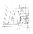
以下に本発明を実施するための形態を図面に基づいて説明する。本実施形態(言い換えると、第1の実施形態)に係る出入口遮断装置は、図1に示されている狭小住宅1の1階部分に設けられ、車両である自動車2を駐車するための駐車スペースである車庫(言い換えると、ガレージ)3の出入口4を遮断するためのものである。   EMBODIMENT OF THE INVENTION Below, the form for implementing this invention is demonstrated based on drawing. The entrance / exit blocking device according to the present embodiment (in other words, the first embodiment) is provided in the first floor portion of the small house 1 shown in FIG. 1 and is a parking space for parking the automobile 2 as a vehicle. This is for shutting off the entrance / exit 4 of the garage (in other words, the garage) 3.

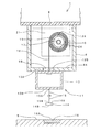
図2には、図1で示されている自動車2が入庫した状態の車庫3の正面図が示されている。道路に面しているこの車庫3の側部(図2では右側部)の奥側には、住宅1へ出入りするための玄関6が設けられており、この車庫3の側部のうち、出入口4から玄関6までは、階段を有する通路7となっている。   FIG. 2 shows a front view of the garage 3 in a state where the automobile 2 shown in FIG. On the back side of the side of the garage 3 facing the road (the right side in FIG. 2), an entrance 6 for entering and exiting the house 1 is provided. From 4 to the entrance 6 is a passage 7 having stairs.

図3は、図2で示されている自動車2が車庫3から出庫し、この車庫3の出入口4が本実施形態に係る出入口遮断装置の遮断体11により遮断されているときを示す図2と同様の図である。   FIG. 3 is a view showing when the automobile 2 shown in FIG. 2 has left the garage 3 and the entrance 4 of the garage 3 is blocked by the blocking body 11 of the entrance blocking apparatus according to the present embodiment. It is the same figure.

この図3に示されているように、車庫3の出入口4を遮断するための本実施形態に係る遮断体11は、上端部が連結された具体的な構造を後述する巻取軸10によって繰り出され、巻き取られる左右2本の紐状部材12と、それぞれの紐状部材12の下端部が連結された横長部材13とを含んで構成されている。なお、左右2本の紐状部材12は、横長部材13の上面部13Aにおけるこの横長部材13の長さ方向の両端部近傍に配置されており、このため、これら2本の紐状部材12は、出入口4の幅方向に離間して配置されている。   As shown in FIG. 3, the blocking body 11 according to the present embodiment for blocking the entrance / exit 4 of the garage 3 is fed out by a take-up shaft 10, which will be described later, with a specific structure in which upper ends are connected. The left and right two string-like members 12 to be wound and the horizontally long member 13 to which the lower ends of the respective string-like members 12 are coupled are configured. The two left and right string-like members 12 are arranged in the upper surface portion 13A of the horizontally long member 13 in the vicinity of both ends in the longitudinal direction of the horizontally long member 13, and therefore, the two string-like members 12 are The doorway 4 is spaced apart in the width direction.

遮断体11を昇降させるための昇降手段となっている巻取軸10は、図2に示されているように、車庫3の出入口4を形成する住宅1の1階部分の開口部4の上縁部4Aに取り付けられたケース部材9の内部に配置されている。   As shown in FIG. 2, the take-up shaft 10 that serves as an elevating means for raising and lowering the blocking body 11 is located above the opening 4 in the first floor portion of the house 1 that forms the doorway 4 of the garage 3. It arrange | positions inside the case member 9 attached to the edge 4A.

中空の棒状部材となっている横長部材13は、車庫3の幅方向(左右方向)の寸法である幅寸法と略同じ長さ寸法を有している。すなわち、横長部材13は、左右方向である横方向に長い寸法を有している中空の棒状部材となっている。   The horizontally long member 13, which is a hollow rod-like member, has substantially the same length dimension as the width dimension that is the dimension in the width direction (left-right direction) of the garage 3. That is, the laterally long member 13 is a hollow rod-like member having a dimension that is long in the lateral direction that is the left-right direction.

図4は、図2の状態における本実施形態に係る出入口遮断装置の縦断面図であり、図5は、図3の状態における本実施形態に係る出入口遮断装置の縦断面図である。   4 is a longitudinal sectional view of the entrance / exit blocking device according to the present embodiment in the state of FIG. 2, and FIG. 5 is a longitudinal sectional view of the entrance / exit blocking device according to the present embodiment in the state of FIG. 3.

図4及び図5に示されているように、左右2本の紐状部材12の上端部12Aは、巻取軸10に連結されており、下端部12Bは、横長部材13の上面部13Aに連結されている。このため、これら2本の紐状部材12のそれぞれは、巻取軸10から横長部材13まで上下方向に延びている。   As shown in FIGS. 4 and 5, the upper ends 12 </ b> A of the left and right two string-like members 12 are connected to the winding shaft 10, and the lower ends 12 </ b> B are connected to the upper surface portion 13 </ b> A of the horizontally long member 13. It is connected. For this reason, each of these two string-like members 12 extends in the vertical direction from the take-up shaft 10 to the horizontally long member 13.

なお、図4及び図5から分かるように、巻取軸10から繰り出され、巻き取られる2本の紐状部材12は、巻取軸10が収納されているケース部材9の底面部9Aに形成されたスリット9Bを通過するようになっている。   As can be seen from FIGS. 4 and 5, the two string-like members 12 that are fed out and wound up from the winding shaft 10 are formed on the bottom surface portion 9 </ b> A of the case member 9 in which the winding shaft 10 is accommodated. It passes through the slit 9B.

また、横長部材13の底面部13Bにおけるこの横長部材13の長さ方向中央部又は略中央部には、上端部15Aが連結された紐状部材15が垂下しており、この紐状部材15の下端部15Bは、円盤状の磁石14の上面部14Aに連結されている。このため、紐状部材15は、磁石14を横長部材13に連結するための連結部材となっている。   Further, a string-like member 15 to which an upper end portion 15A is coupled hangs down at the center in the longitudinal direction of the horizontally-long member 13 in the bottom surface portion 13B of the horizontally-long member 13 or substantially at the center. The lower end portion 15B is connected to the upper surface portion 14A of the disk-shaped magnet 14. For this reason, the string-like member 15 is a connecting member for connecting the magnet 14 to the horizontally long member 13.

前述したように、図3は、車庫3の出入口4が本実施形態に係る出入口遮断装置の遮断体11により遮断されているときを示す図であるが、このときの遮断体11を構成する横長部材13は、駐車面である地面5に着地するものではない。すなわち、横長部材13の高さ位置は、車庫3へ車両や人の侵入を妨げる高さ位置(例えば、図3で示されている本実施形態のように、成人の膝の高さ位置から腰の高さ位置ぐらいまでの範囲)となっている。   As described above, FIG. 3 is a diagram showing the time when the doorway 4 of the garage 3 is blocked by the blocking body 11 of the doorway blocking device according to the present embodiment. The member 13 does not land on the ground 5 which is a parking surface. That is, the height position of the horizontally long member 13 is set to a height position that prevents entry of a vehicle or a person into the garage 3 (for example, from the height position of an adult's knee as in the present embodiment shown in FIG. 3). The range up to about the height position of).

地面5には、車庫3の出入口4が遮断体11により遮断されているときに磁石14が吸着する磁性体16が配置されている。この磁性体16の上面部16Aは、地面5と面一又は略面一状態となっている。すなわち、磁性体16は、上面部16Aが地面5に露出した状態で地中に埋設されている。地面5における磁性体16の配置位置は、車庫3の出入口4が遮断体11により遮断されているときにおける磁石14の位置と対応又は略対応する位置となっている。   On the ground 5, there is disposed a magnetic body 16 to which the magnet 14 is attracted when the doorway 4 of the garage 3 is blocked by the blocking body 11. The upper surface portion 16A of the magnetic body 16 is flush with or substantially flush with the ground 5. That is, the magnetic body 16 is buried in the ground with the upper surface portion 16 </ b> A exposed to the ground 5. The arrangement position of the magnetic body 16 on the ground 5 corresponds to or substantially corresponds to the position of the magnet 14 when the doorway 4 of the garage 3 is blocked by the blocking body 11.

なお、磁性体16の上面部16Aの面積(表面積)は、磁石14の底面部14Bの面積(表面積)よりも大きくなっている。これは、前述したように、磁石14が紐状部材15を介して横長部材13に連結されているため、車庫3の出入口4が遮断体11により遮断されているとき、磁性体16に吸着している磁石14が風圧等で横移動し、磁石14が磁性体16から外れてしまうおそれがあることを考慮したものである。   The area (surface area) of the upper surface portion 16A of the magnetic body 16 is larger than the area (surface area) of the bottom surface portion 14B of the magnet 14. As described above, since the magnet 14 is connected to the horizontally long member 13 via the string-like member 15, when the entrance 4 of the garage 3 is blocked by the blocking body 11, the magnet 14 is attracted to the magnetic body 16. This is because it is considered that the magnet 14 may move laterally due to wind pressure or the like, and the magnet 14 may be detached from the magnetic body 16.

本実施形態では、図2及び図4で示されているように、自動車2が車庫3に入庫しているときには、横長部材13は、この横長部材13の上面部13Aが巻取軸10のケース部材9の底面部9Aに接触した状態で、車庫3の出入口4の上方に配置されるようになっている。   In the present embodiment, as shown in FIGS. 2 and 4, when the automobile 2 is in the garage 3, the horizontally long member 13 has a case where the upper surface portion 13 </ b> A of the horizontally long member 13 is the winding shaft 10. In contact with the bottom surface 9 </ b> A of the member 9, the member 9 is arranged above the entrance / exit 4 of the garage 3.

図6は、図4及び図5で示されている巻取軸10の内部構造を示す図である。なお、この図6では、巻取軸10から繰り出され、巻き取られる紐状部材12の表示は省略されている。   FIG. 6 is a diagram showing an internal structure of the winding shaft 10 shown in FIGS. 4 and 5. In addition, in this FIG. 6, the display of the string-like member 12 drawn out and wound up from the winding shaft 10 is omitted.

この図6に示されているように、中空部材からなる巻取軸10は、両端の第1及び第2中心軸17,18を中心に回転自在となっている。第1中心軸17は、住宅1の開口部4の上縁部4Aを形成する天井部材8に取り付けられた左右のブラケット21,22のうちの一方のブラケット21に結合されて回転しない軸となっており、この第1中心軸17は、巻取軸10の一方の開口端部に結合された軸受け部材19の内部に挿入されている。   As shown in FIG. 6, the winding shaft 10 made of a hollow member is rotatable around the first and second central shafts 17 and 18 at both ends. The first central shaft 17 is coupled to one of the left and right brackets 21 and 22 attached to the ceiling member 8 that forms the upper edge 4A of the opening 4 of the house 1 and does not rotate. The first central shaft 17 is inserted into a bearing member 19 coupled to one open end of the winding shaft 10.

巻取軸10の内部には、この巻取軸10に結合されていて巻取軸10と一体に回転する回転部材51が組み込まれており、第2中心軸18は、回転部材51に結合されているために回転する軸となっており、この第2中心軸18は、他方のブラケット22に結合された軸受け部材20の内部に回転自在に挿入されている。   Inside the winding shaft 10, a rotating member 51 coupled to the winding shaft 10 and rotating integrally with the winding shaft 10 is incorporated, and the second central shaft 18 is coupled to the rotating member 51. Therefore, the second central shaft 18 is rotatably inserted into the bearing member 20 coupled to the other bracket 22.

また、巻取軸10の内部には、この巻取軸10に結合されていて巻取軸10と一体に回転する回転部材23が組み込まれ、この回転部材23と第1中心軸17とに戻しばね24の両端が連結されている。   In addition, a rotating member 23 coupled to the winding shaft 10 and rotating integrally with the winding shaft 10 is incorporated in the winding shaft 10, and is returned to the rotating member 23 and the first central shaft 17. Both ends of the spring 24 are connected.

巻取軸10の内部に収納されているこの戻しばね24には、紐状部材12を下方へ繰り出すために巻取軸10が正回転したときには、戻しばね力が蓄圧されることになる。   This return spring 24 housed inside the take-up shaft 10 accumulates the return spring force when the take-up shaft 10 rotates forward in order to feed the string-like member 12 downward.

このように、巻取軸10の内部には、この巻取軸10から紐状部材12が繰り出される際に、回転する巻取軸10でばね力が蓄圧される戻しばね24が配置されている。   As described above, the return spring 24 in which the spring force is accumulated by the rotating winding shaft 10 when the string-like member 12 is drawn out from the winding shaft 10 is disposed inside the winding shaft 10. .

そして、本実施形態では、戻しばね24のばね力は、常に遮断体11の自重(巻取軸10から繰り出されている紐状部材12の重量と、横長部材13の重量と、紐状部材15の重量と、磁石14の重量の合計)と同じ又はこれよりも大きいものとなっている。   In this embodiment, the spring force of the return spring 24 is always the weight of the blocking body 11 (the weight of the string-like member 12 fed out from the take-up shaft 10, the weight of the horizontally long member 13, and the string-like member 15). And the sum of the weights of the magnets 14) or larger than this.

このため、巻取軸10には、紐状部材12を巻き取る方向の回転力(逆回転力)が常に作用している。すなわち、巻取軸10には、紐状部材12を巻き取るために逆回転しようとする力が常に作用している。   For this reason, a rotational force (reverse rotational force) in the direction of winding the string-like member 12 always acts on the winding shaft 10. That is, the winding shaft 10 is always subjected to a force for reverse rotation to wind the string-like member 12.

次に、本実施形態に係る出入口遮断装置の動作について説明する。   Next, the operation of the doorway shut-off device according to this embodiment will be described.

まず、車庫3の出入口4を遮断体11で遮断させる作業について説明する。   First, the operation of blocking the entrance / exit 4 of the garage 3 with the blocking body 11 will be described.

本実施形態では、自動車2を車庫3から完全に出庫させた後、自動車2の運転者や同乗者あるいは自動車2で外出しない住宅1の住人等が、車庫3の出入口4を遮断体11で遮断する作業を行う。   In this embodiment, after the automobile 2 is completely removed from the garage 3, a driver of the automobile 2, a passenger, a resident of the house 1 who does not go out of the automobile 2, etc. shuts the entrance / exit 4 of the garage 3 with the blocking body 11. Work to do.

この遮断作業は、作業者が、円盤状の磁石14あるいは紐状部材15に手を掛け、この磁石14又は紐状部材15を下に引っ張ることにより行う。これにより、上面部13Aがケース部材9の底面部9Aに接触していた横長部材13が下降していくことになる。この引っ張り作業は、磁石14が磁性体16に接触して吸着するまで、すなわち、磁石14が地面5に接地するまで行う。なお、作業者が、引っ張り作業の途中で磁石14あるいは紐状部材15から手を離すと、巻取軸10の内部に配置されている戻しばね24に蓄圧されたばね力で巻取軸10が逆回転する。これにより、紐状部材12が巻取軸10に巻き取られるため、遮断体11は上昇して図2や図4で示された状態に戻る。   This blocking operation is performed by the operator placing a hand on the disk-shaped magnet 14 or the string-like member 15 and pulling the magnet 14 or the string-like member 15 downward. Accordingly, the horizontally long member 13 whose upper surface portion 13A is in contact with the bottom surface portion 9A of the case member 9 is lowered. This pulling operation is performed until the magnet 14 comes into contact with and attracts the magnetic body 16, that is, until the magnet 14 contacts the ground 5. When the operator releases his / her hand from the magnet 14 or the string-like member 15 during the pulling operation, the winding shaft 10 is reversed by the spring force accumulated in the return spring 24 disposed inside the winding shaft 10. Rotate. Thereby, since the string-like member 12 is wound up by the winding shaft 10, the blocking body 11 rises and returns to the state shown in FIG. 2 and FIG.

磁石14が磁性体16に吸着する力は、巻取軸10の逆回転力よりも大きくなっている。このため、上述した引っ張り作業により磁石14が磁性体16に吸着することで、遮断体11は、図3に示された状態が保持(維持)される。すなわち、遮断体11により出入口4が遮断された状態が保持される。   The force with which the magnet 14 is attracted to the magnetic body 16 is larger than the reverse rotational force of the winding shaft 10. For this reason, when the magnet 14 is attracted to the magnetic body 16 by the pulling operation described above, the state of the blocking body 11 shown in FIG. 3 is maintained (maintained). That is, the state where the doorway 4 is blocked by the blocking body 11 is maintained.

このため、磁石14と磁性体16は、遮断体11による出入口4の遮断状態を保持するための遮断状態保持手段を構成している。そして、磁石14は、紐状部材15により横長部材13に連結された係止部材となっており、磁性体16は、駐車面である地面5に設けられ、磁石14が係止する被係止部材となっている。   For this reason, the magnet 14 and the magnetic body 16 constitute a blocking state holding means for holding the blocking state of the entrance / exit 4 by the blocking body 11. The magnet 14 is a locking member connected to the horizontally long member 13 by a string-like member 15, and the magnetic body 16 is provided on the ground 5 that is a parking surface, and is locked by the magnet 14. It is a member.

また、本実施形態では、磁石14や紐状部材15は、遮断体11を下降させるための操作部材となっている。   In the present embodiment, the magnet 14 and the string-like member 15 are operation members for lowering the blocking body 11.

なお、本実施形態において、磁石14と磁性体16を逆にしてよい。すなわち、円盤状の磁性体を横長部材13に紐状部材15を介して連結し、地面5には、磁石を配置するようにしてもよい。   In the present embodiment, the magnet 14 and the magnetic body 16 may be reversed. That is, a disk-like magnetic body may be connected to the horizontally long member 13 via the string-like member 15, and a magnet may be disposed on the ground 5.

また、本実施形態において、磁石14をフック部材とし、磁性体16をフック部材が係止可能なピン部材又はリング部材等としてもよい。   In the present embodiment, the magnet 14 may be a hook member, and the magnetic body 16 may be a pin member or a ring member that can be hooked to the hook member.

次に、遮断体11により車庫3の出入口4が遮断されている状態を解除する作業について説明する。   Next, an operation for releasing the state where the doorway 4 of the garage 3 is blocked by the blocking body 11 will be described.

この作業は、車庫3から出庫していた自動車2を再び車庫3に入庫させるときに行われるものであり、作業者(前述したように、自動車2の運転者や同乗者あるいは自動車2で外出しない住宅1の住人等)は、磁石14あるいは紐状部材15に手を掛けてこの磁石14又は紐状部材15を上に引っ張り、磁性体16に吸着している磁石14をこの磁性体16から切り離せばよい。この後、作業者は、磁石14あるいは紐状部材15から手を離せばよい。   This operation is performed when the automobile 2 that has been delivered from the garage 3 is re-entered into the garage 3, and the operator (as described above, the driver of the automobile 2, the passenger, or the automobile 2 does not go out). A resident of the house 1, for example, puts his hand on the magnet 14 or the string-like member 15 and pulls the magnet 14 or the string-like member 15 upward to separate the magnet 14 adsorbed on the magnetic body 16 from the magnetic body 16. That's fine. Thereafter, the operator may release the hand from the magnet 14 or the string-like member 15.

前述したように、巻取軸10には、紐状部材12を巻き取る方向の回転力(逆回転力)が常に作用している。このため、磁石14を磁性体16から切り離した後は、紐状部材12が巻取軸10により巻き取られ、これにより、横長部材13は、図2及び図4に示す状態となるまで上昇する。   As described above, the rotational force (reverse rotational force) in the direction of winding the string-like member 12 is constantly acting on the winding shaft 10. For this reason, after separating the magnet 14 from the magnetic body 16, the string-like member 12 is taken up by the take-up shaft 10, and thereby the horizontally long member 13 rises to the state shown in FIGS. 2 and 4. .

このように、本実施形態では、巻取軸10とこの巻取軸10の内部に配置されている戻しばね24は、遮断体11を昇降させるための昇降手段を構成している。   Thus, in the present embodiment, the winding shaft 10 and the return spring 24 disposed inside the winding shaft 10 constitute lifting means for lifting and lowering the blocking body 11.

なお、本実施形態では、図2や図4で示されているように車庫3に自動車2が入庫している状態において、図3や図5で示されているように、遮断体11を下降させて出入口4が遮断体11で遮断された状態とすることもできる。   In the present embodiment, as shown in FIGS. 3 and 5, the blocking body 11 is lowered while the automobile 2 is in the garage 3 as shown in FIGS. 2 and 4. Thus, the entrance / exit 4 may be blocked by the blocking body 11.

以上説明した本実施形態では、駐車スペースである車庫3の出入口4を遮断するための出入口遮断装置は、車庫3の駐車面である地面5の上方に配置されている。   In this embodiment described above, the entrance / exit blocking device for blocking the entrance / exit 4 of the garage 3 that is a parking space is disposed above the ground 5 that is the parking surface of the garage 3.

このため、本実施形態によると、地中に埋設されていた従来の出入口遮断装置と比較して、設置作業がより簡単に行えるようになる。   For this reason, according to this embodiment, compared with the conventional entrance-exit blocker embed | buried under the ground, installation work can be performed more easily.

なお、本実施形態において、自動車2が車庫3に入庫しているとき、出入口4を遮断体11により遮断させることもできる。ただし、自動車2の長さ寸法(前後方向の寸法)が、車庫3の長さ寸法よりも小さい場合に限る。すなわち、車庫3に入庫された状態の自動車2が出入口4からはみ出していない場合に限る。   In this embodiment, when the automobile 2 is in the garage 3, the entrance / exit 4 can be blocked by the blocking body 11. However, it is limited to the case where the length dimension (the dimension in the front-rear direction) of the automobile 2 is smaller than the length dimension of the garage 3. That is, it is limited to the case where the automobile 2 in the garage 3 is not protruding from the entrance 4.

なお、本実施形態において、遮断体11を下降させる作業は、横長部材13に被係止部を設けるとともに、この被係止部に係止する係止部を有していて、持ち上げたときに被係止部に届く長さを有する棒状部材を用意し、横長部材13の被係止部に係止部を係止させた棒状部材を下に引っ張る(引っ張り降ろす)ことにより行うようにしてもよい。   In the present embodiment, the operation of lowering the blocking body 11 is performed when the horizontally long member 13 is provided with a locked portion and has a locking portion that is locked to the locked portion and is lifted. A rod-shaped member having a length that reaches the locked portion is prepared, and the rod-shaped member having the locking portion locked to the locked portion of the laterally long member 13 is pulled down (pulled down). Good.

図7は、第2の実施形態に係る駐車スペースの出入口遮断装置を示す図3と同様の図である。なお、以下で説明する各実施形態において、前述した第1の実施形態と同じ部材については、同じ符号を付し、その説明は省略する。   FIG. 7 is a view similar to FIG. 3 showing the parking space doorway shut-off device according to the second embodiment. In each embodiment described below, the same members as those in the first embodiment described above are denoted by the same reference numerals, and the description thereof is omitted.

この図7で示されているように、本実施形態に係る遮断体25では、巻取軸10によって繰り出され、巻き取られる被巻取部材である紐状部材12の本数は、前述した第1の実施形態と同様に、2本となっている。   As shown in FIG. 7, in the blocking body 25 according to the present embodiment, the number of the string-like members 12 that are to be taken up and taken up by the take-up shaft 10 is the first mentioned above. As in the embodiment, there are two.

しかし、本実施形態に係る遮断体25では、2本の紐状部材12のうちの一方の紐状部材12の上端部は、巻取軸10の軸方向の両端部のうちの一方の端部近傍に取り付けられ、下端部は、横長部材13の上面部13Aにおけるこの横長部材13の長さ方向中央部近傍に取り付けられている。また、他方の紐状部材12の上端部は、巻取軸10の軸方向の両端部のうちの他方の端部近傍に取り付けられ、下端部は、横長部材13の上面部13Aにおけるこの横長部材13の長さ方向中央部近傍に取り付けられている。そして、これら2本の紐状部材12は互いに交差しないよう配置されている。   However, in the blocking body 25 according to the present embodiment, the upper end portion of one of the two string-like members 12 is one end portion of both end portions in the axial direction of the winding shaft 10. The lower end is attached to the vicinity of the central portion in the length direction of the horizontally long member 13 on the upper surface portion 13 </ b> A of the horizontally long member 13. Further, the upper end portion of the other string-like member 12 is attached in the vicinity of the other end portion of the axial ends of the winding shaft 10, and the lower end portion is the horizontally long member on the upper surface portion 13 </ b> A of the horizontally long member 13. 13 is attached in the vicinity of the central portion in the length direction. And these two string-like members 12 are arrange | positioned so that it may not mutually cross.

すなわち、本実施形態では、それぞれの紐状部材12の上端部の配置位置と下端部の配置位置は、巻取軸10の軸方向(図7では、左右方向)にずれている。また、巻取軸10における2本のうちの一方の紐状部材12が巻き取られる部分と、他方の紐状部材12が巻き取られる部分とは、巻取軸10の軸方向に離間している。   That is, in this embodiment, the arrangement position of the upper end part and the arrangement position of the lower end part of each string-like member 12 are shifted in the axial direction of the winding shaft 10 (left and right direction in FIG. 7). Further, the portion of the winding shaft 10 where one of the string-like members 12 is wound is separated from the portion of the other winding member 12 where the other string-like member 12 is wound away in the axial direction of the winding shaft 10. Yes.

これにより、これら2本の紐状部材12が巻取軸10に巻き取られるとき、これら2本の紐状部材12は、巻取軸10にこの巻取軸10の径方向に重ならずに螺旋状に巻き取られることになる。   Thereby, when these two string-like members 12 are wound around the winding shaft 10, these two string-like members 12 do not overlap the winding shaft 10 in the radial direction of the winding shaft 10. It will be wound up in a spiral.

このため、本実施形態によると、2本の紐状部材12が巻取軸10に巻き取られるとき、これらの紐状部材12の巻き径を小さいものとすることができる。   For this reason, according to this embodiment, when the two string-like members 12 are wound around the take-up shaft 10, the winding diameter of these string-like members 12 can be made small.

なお、本実施形態において、2本の紐状部材12のうちの一方の紐状部材12の上端部は、巻取軸10の軸方向の中央部近傍に取り付け、下端部は、横長部材13の上面部13Aにおけるこの横長部材13の長さ方向の両端部のうちの一方の端部近傍に取り付け、また、他方の紐状部材12の上端部は、巻取軸10の軸方向の中央部近傍に取り付け、下端部は、横長部材13の上面部13Aにおけるこの横長部材13の長さ方向の両端部のうちの他方の端部近傍に取り付け、これら2本の紐状部材12は互いに交差しないよう配置するようにしてもよい。   In the present embodiment, the upper end portion of one of the two string-like members 12 is attached in the vicinity of the central portion in the axial direction of the take-up shaft 10, and the lower end portion of the horizontally long member 13 is attached. The upper surface portion 13 </ b> A is attached in the vicinity of one end portion of both ends in the length direction of the horizontally long member 13, and the upper end portion of the other string-like member 12 is in the vicinity of the central portion in the axial direction of the winding shaft 10. The lower end is attached to the vicinity of the other end of the lengthwise direction of the horizontally long member 13 on the upper surface portion 13A of the horizontally long member 13, so that the two string-like members 12 do not cross each other. It may be arranged.

図8は、第3の実施形態に係る駐車スペースの出入口遮断装置を示す図3と同様の図である。   FIG. 8 is a view similar to FIG. 3 showing the entrance / exit blocking device for the parking space according to the third embodiment.

この図8で示されているように、本実施形態に係る遮断体26では、巻取軸10によって繰り出され、巻き取られる被巻取部材は、防水性、耐久性を有する1枚のシート状部材27となっている。   As shown in FIG. 8, in the blocking body 26 according to the present embodiment, the member to be wound that is fed and wound by the winding shaft 10 is a single sheet having waterproofness and durability. Member 27 is formed.

本実施形態によると、前述した第1及び第2の実施形態と比較して、車庫3の内部を外部からより見えにくくさせることができるという効果も得られる。   According to this embodiment, the effect that the inside of the garage 3 can be made harder to see from the outside is also obtained as compared with the first and second embodiments described above.

なお、本実施形態において、被巻取部材は、複数枚のシート状部材を車庫3の幅方向に並設したもので構成するようにしてもよい。   In the present embodiment, the member to be wound may be constituted by a plurality of sheet-like members arranged in parallel in the width direction of the garage 3.

図9は、第4の実施形態に係る駐車スペースの出入口遮断装置を示す図3と同様の図である。   FIG. 9 is a view similar to FIG. 3 showing the parking space doorway shut-off device according to the fourth embodiment.

本実施形態に係る遮断体29は、車庫3の出入口4と、この車庫3の側部に設けられた玄関6への通路7の出入口を遮断するものとなっている。   The blocking body 29 according to the present embodiment is configured to block the entrance / exit of the garage 3 and the entrance / exit of the passage 7 to the entrance 6 provided on the side of the garage 3.

このため、遮断体29は、車庫3の出入口4と通路7の出入口に跨る幅寸法を有している。   For this reason, the blocking body 29 has a width dimension straddling the doorway 4 of the garage 3 and the doorway of the passage 7.

すなわち、図9に示されているように、遮断体29を構成する横長部材31は、車庫3の出入口4と通路7の出入口に跨る長さ寸法(左右方向の寸法)を有している。   That is, as shown in FIG. 9, the horizontally long member 31 that constitutes the blocking body 29 has a length dimension (dimension in the left-right direction) straddling the entrance / exit 4 of the garage 3 and the entrance / exit of the passage 7.

このため、横長部材31の上面部13Aに下端部が連結されている3本の紐状部材30を繰り出し、巻き取るための図示されない巻取軸の長さ寸法(左右方向の寸法)も、車庫3の出入口4と通路7の出入口に跨る長さ寸法を有しており、この巻取軸を収納するためのケース部材28も、図9で示されているように、車庫3の出入口4と通路7の出入口に跨る長さ寸法を有している。そして、このケース部材28の底面部28Aに設けられているスリット28Bの長さ寸法も、車庫3の出入口4と通路7の出入口に跨る長さ寸法を有している。   For this reason, the length dimension (dimension in the left-right direction) of a winding shaft (not shown) for feeding and winding the three string-like members 30 whose lower ends are connected to the upper surface portion 13A of the horizontally long member 31 is also the garage. 3 and a case member 28 for accommodating the take-up shaft is also provided with the entrance 4 of the garage 3 as shown in FIG. It has a length dimension straddling the entrance / exit of the passage 7. The length dimension of the slit 28 </ b> B provided in the bottom surface portion 28 </ b> A of the case member 28 also has a length dimension straddling the entrance / exit 4 of the garage 3 and the entrance / exit of the passage 7.

なお、3本の紐状部材30は、横長部材31の上面部31Aに車庫3の幅方向に離間して連結されており、この横長部材31の底面部31Bにおける長さ方向中央部又は略中央部には、磁石14を横長部材31に連結するための紐状部材15の上端部が連結されている。   The three string-like members 30 are connected to the upper surface portion 31A of the laterally long member 31 so as to be separated from each other in the width direction of the garage 3. The upper end portion of the string-like member 15 for connecting the magnet 14 to the horizontally long member 31 is connected to the portion.

本実施形態によると、車庫3の出入口4と通路7の出入口に跨る幅寸法を有している遮断体29により、車庫3への車両や人の侵入を遮断することができるだけでなく、玄関6への人や車両(自動車ではなく、自動二輪車や自転車等)の侵入を遮断することができる。   According to this embodiment, not only can the entrance of the vehicle and the person into the garage 3 be blocked by the blocking body 29 having a width across the entrance 4 of the garage 3 and the entrance of the passage 7, but also the entrance 6 It is possible to block the entry of people and vehicles (motorcycles, bicycles, etc., not cars).

図10は、第5の実施形態(言い換えると、前述した第1の実施形態の変形例)に係る出入口遮断装置を示す図3と同様の図である。図11は、図10で示されている出入口遮断装置の巻取軸10の内部構造を示す図6と同様の図である。   FIG. 10 is a view similar to FIG. 3 showing the doorway shut-off device according to the fifth embodiment (in other words, a modification of the above-described first embodiment). FIG. 11 is a view similar to FIG. 6 showing the internal structure of the winding shaft 10 of the doorway shut-off device shown in FIG.

図11に示されているように、前述の第1〜第4の実施形態と同様に、巻取軸10の内部には、戻しばね24が配置されている。   As shown in FIG. 11, a return spring 24 is disposed inside the winding shaft 10 as in the first to fourth embodiments described above.

しかし、本実施形態では、この戻しばね24のばね力は、常に遮断体11の自重よりも小さくなっている。すなわち、本実施形態では、戻しばね24のばね力は、常に遮断体11の自重(巻取軸10から繰り出されている紐状部材12の重量と、横長部材13の重量と、具体的な構造を後述する被係止部材33の重量と、紐状部材15の重量と、磁石14の重量の合計)よりも小さくなっている。   However, in this embodiment, the spring force of the return spring 24 is always smaller than the dead weight of the blocking body 11. That is, in the present embodiment, the spring force of the return spring 24 is always the weight of the blocking body 11 (the weight of the string-like member 12 fed out from the winding shaft 10, the weight of the laterally long member 13, and the specific structure. (The sum of the weight of the locked member 33, the weight of the string-like member 15, and the weight of the magnet 14).

このため、巻取軸10には、紐状部材12を繰り出す方向の回転力(正回転力)が常に作用している。すなわち、巻取軸10には、紐状部材12を繰り出すために正回転しようとする力が常に作用している。   For this reason, a rotational force (positive rotational force) in the direction in which the string-like member 12 is fed out always acts on the winding shaft 10. That is, the winding shaft 10 is always subjected to a force to rotate forward in order to feed out the string-like member 12.

図10で示されているとおり、横長部材13の上面部13Aにおけるこの横長部材13の長さ方向中央部には、上述した被係止部材33が取り付けられており、この被係止部材33には被係止孔33Aが形成されている。また、図10及び図11に示すように、ケース部材9の底面部9Aの上面(スリット9Bの部分を除く)であって、被係止部材33の略真上の位置には、具体的な構造を後述する係止装置34が配置されている。   As shown in FIG. 10, the above-described locked member 33 is attached to the central portion in the length direction of the horizontally long member 13 on the upper surface portion 13 </ b> A of the horizontally long member 13. A to-be-latched hole 33A is formed. Further, as shown in FIGS. 10 and 11, the upper surface of the bottom surface portion 9 </ b> A of the case member 9 (excluding the slit 9 </ b> B portion), and a position just above the locked member 33, A locking device 34 whose structure will be described later is arranged.

図12は、紐状部材12が巻取軸10から繰り出されて下降してきた遮断体11が出入口4を遮断している状態を示す図5と同様の図である。また、図13は、図12の状態から、紐状部材12が巻取軸10に巻き取られて上昇してきた遮断体11の横長部材13の上面部13Aがケース部材9の底面部9Aの下面に当接している状態、すなわち、出入口4の非遮断状態が保持されている状態を示す図4と同様の図である。   FIG. 12 is a view similar to FIG. 5 showing a state in which the blocking body 11, which has been lowered as the string-like member 12 is drawn out from the winding shaft 10, blocks the entrance / exit 4. 13 shows that the upper surface portion 13A of the horizontally long member 13 of the blocking body 11 in which the string-like member 12 has been wound up by the winding shaft 10 from the state of FIG. 12 is the lower surface of the bottom surface portion 9A of the case member 9. It is a figure similar to FIG. 4 which shows the state which is contact | abutting, ie, the state by which the non-blocking state of the entrance / exit 4 is hold | maintained.

係止装置34は、図13に示されているように、遮断体11の紐状部材12が巻取軸10に巻き取られることによって横長部材13の上面部13Aがケース部材9の底面部9Aの下面に当接しているときに、被係止部材33の被係止孔33Aに挿入係止することによって遮断体11の下降を阻止するための係止部材60を備えている。   As shown in FIG. 13, the locking device 34 is configured such that the upper surface portion 13 </ b> A of the horizontally long member 13 becomes the bottom surface portion 9 </ b> A of the case member 9 when the string-like member 12 of the blocking body 11 is wound around the winding shaft 10. A locking member 60 is provided to prevent the blocking body 11 from descending by being inserted and locked into the locked hole 33A of the locked member 33 when it is in contact with the lower surface of the locked member 33.

上下に揺動自在となっている通常時の係止部材60は、係止装置34の内部に設けられている具体的な構造を後述するストップ機構70の作動によって被係止孔33Aに挿入係止した水平姿勢となっており、これにより、出入口4の非遮断状態が保持(維持)される。   The normal locking member 60 that is swingable up and down is inserted into the locked hole 33A by operating a stop mechanism 70 described later with a specific structure provided inside the locking device 34. The horizontal posture is stopped, and thereby the non-blocking state of the doorway 4 is maintained (maintained).

上述したように、巻取軸10には、紐状部材12を繰り出すために正回転しようとする力が常に作用しているため、遮断体11の紐状部材12が巻取軸10に巻き取られた状態となっているときには、この巻取軸10の正回転を阻止する必要がなる。   As described above, the winding shaft 10 is always subjected to a force to rotate forward in order to feed the string-like member 12, so that the string-like member 12 of the blocking body 11 is wound around the take-up shaft 10. When it is in the state, it is necessary to prevent the winding shaft 10 from rotating forward.

このため、本実施形態では、遮断体11の紐状部材12が巻取軸10に巻き取られ、横長部材13の上面部13Aがケース部材9の底面部9Aの下面に当接している状態となっている非遮断状態を保持するための非遮断状態保持手段を備えており、この非遮断状態保持手段は、上述した被係止部材33と、係止部材60を有する係止装置34とを含んで構成されるものとなっている。   For this reason, in this embodiment, the string-like member 12 of the blocking body 11 is wound around the take-up shaft 10, and the upper surface portion 13A of the horizontally long member 13 is in contact with the lower surface of the bottom surface portion 9A of the case member 9. The non-blocking state holding means for holding the non-blocking state is provided. The non-blocking state holding unit includes the above-described locked member 33 and the locking device 34 having the locking member 60. It is configured to include.

図10で示されているように、車庫3の出入口4を形成している狭小住宅1の開口部4の側壁46の内部には、図13で示されている状態の遮断体11を下降させるために上述したストップ機構70の作動を解除するための具体的な構造を後述する操作部材42が配置されている。この操作部材42には、紐状部材であるワイヤー35の一端が連結されており、このワイヤー35は、側壁46の内部に配置されている上下2個のローラ37,38で方向変換されて係止装置34まで延びている。   As shown in FIG. 10, the blocking body 11 in the state shown in FIG. 13 is lowered inside the side wall 46 of the opening 4 of the narrow house 1 that forms the doorway 4 of the garage 3. Therefore, an operation member 42, which will be described later with a specific structure for releasing the operation of the stop mechanism 70 described above, is disposed. One end of a wire 35 that is a string-like member is connected to the operation member 42, and the direction of the wire 35 is changed by two upper and lower rollers 37 and 38 disposed inside the side wall 46. It extends to the stop device 34.

操作部材42の回動操作によりワイヤー35が牽引動作することでストップ機構70の作動が解除されると、後述するように、係止部材60がばね力により下向きの揺動姿勢となり、遮断体11が下降可能な状態に切り換えられる。   When the operation of the stop mechanism 70 is released by the pulling operation of the wire 35 by the turning operation of the operation member 42, the locking member 60 assumes a downward swinging posture by the spring force, as will be described later, and the blocking body 11. Is switched to a state where it can be lowered.

この結果、遮断体11は、この遮断体11の自重(巻取軸10から繰り出されている紐状部材12の重量と、横長部材13の重量と、被係止部材33の重量と、紐状部材15の重量と、磁石14の重量の合計)による下降を開始する。   As a result, the blocking body 11 has its own weight (the weight of the string-like member 12 fed out from the winding shaft 10, the weight of the horizontally long member 13, the weight of the locked member 33, and the string-like shape. The descent by the sum of the weight of the member 15 and the weight of the magnet 14 is started.

すなわち、操作部材42が操作されることより、非遮断状態保持手段による出入口4の非遮断状態の保持が解除され、巻取軸10から紐状部材12が繰り出されることにより、横長部材13は、図10に示されている所定の高さ位置まで下降し、出入口4が遮断体11により遮断された状態となる。   That is, when the operation member 42 is operated, the non-blocking state holding of the entrance / exit 4 by the non-blocking state holding means is released, and when the string-like member 12 is drawn out from the winding shaft 10, the horizontally long member 13 is 10 is lowered to a predetermined height position shown in FIG. 10, and the entrance / exit 4 is blocked by the blocking body 11.

前述したように、本実施形態では、巻取軸10の内部に配置された戻しばね24のばね力は、常に遮断体11の自重よりも小さくなっている。また、本実施形態では、非遮断状態保持手段による出入口4の非遮断状態の保持が解除された後における巻取軸10の正回転を停止させるための手段は備えられていない。   As described above, in this embodiment, the spring force of the return spring 24 arranged inside the winding shaft 10 is always smaller than the dead weight of the blocking body 11. Moreover, in this embodiment, the means for stopping the forward rotation of the winding shaft 10 after the non-blocking state holding of the entrance / exit 4 by the non-blocking state holding unit is released is not provided.

このため、本実施形態では、操作部材42が操作されることで非遮断状態保持手段による出入口4の非遮断状態の保持が解除された後、巻取軸10の正回転は、上端部12Aを除く紐状部材12の全部が繰り出されるまで継続することになる。   For this reason, in this embodiment, after the operation member 42 is operated to release the non-blocking state holding of the entrance / exit 4 by the non-blocking state holding means, the forward rotation of the winding shaft 10 causes the upper end 12A to move. This is continued until the entire string-like member 12 is drawn out.

この結果、図12で示されている状態、すなわち、出入口4が遮断体11により遮断されている状態においては、上端部12Aを除く紐状部材12が巻取軸10の最下部から垂下した状態となる。   As a result, in the state shown in FIG. 12, that is, in the state where the entrance / exit 4 is blocked by the blocking body 11, the string-like member 12 excluding the upper end portion 12 </ b> A hangs down from the lowermost portion of the winding shaft 10. It becomes.

図10及び図12から分かるように、本実施形態では、紐状部材12の巻取軸10からの繰り出し量、言い換えると、巻取軸10から繰り出される紐状部材12の長さは、出入口4を遮断しているときの遮断体11の横長部材13の高さ位置が、前述した第1〜第4の各実施形態における横長部材13の高さ位置と同じ又は略同じとなるような繰り出し量となっている。   As can be seen from FIGS. 10 and 12, in this embodiment, the feed amount of the string-like member 12 from the take-up shaft 10, in other words, the length of the string-like member 12 that is fed from the take-up shaft 10 is the entrance / exit 4. The amount of feeding so that the height position of the horizontally long member 13 of the blocking body 11 is the same as or substantially the same as the height position of the horizontally long member 13 in each of the first to fourth embodiments described above. It has become.

図10及び図12で示されている状態においては、紐状部材12には、少なくとも横長部材13の重量と被係止部材33の重量を合計した下向きの荷重が掛かることになり、このため、紐状部材12には下向きの緊張力が発生し、この紐状部材12は、上述したように、巻取軸10の最下部から垂下した状態(言い換えると、鉛直方向に真っ直ぐ延びた状態)となる。   In the state shown in FIGS. 10 and 12, the string-like member 12 is subjected to a downward load that is a total of at least the weight of the horizontally long member 13 and the weight of the locked member 33. A downward tension is generated in the string-like member 12, and as described above, the string-like member 12 hangs down from the lowermost part of the winding shaft 10 (in other words, a state in which the string-like member 12 extends straight in the vertical direction). Become.

なお、図10及び図12で示されている状態においては、磁石14は、地面5に配置されている磁性体16の上面に載置されるとともに、この磁性体16に吸着しているため、紐状部材12には、磁石14の重量分の荷重は掛からない。   In the state shown in FIGS. 10 and 12, the magnet 14 is placed on the upper surface of the magnetic body 16 disposed on the ground 5 and is attracted to the magnetic body 16. A load corresponding to the weight of the magnet 14 is not applied to the string-like member 12.

図11に示されているように、本実施形態では、巻取軸10が紐状部材12を繰り出すために正回転するときには、この巻取軸10の回転速度を減速させるための減速装置32が、巻取軸10の回転する軸である第2中心軸18に取り付けられている。   As shown in FIG. 11, in this embodiment, when the winding shaft 10 rotates forward to feed out the string-like member 12, a speed reducing device 32 for reducing the rotational speed of the winding shaft 10 is provided. The second central shaft 18, which is a rotating shaft of the winding shaft 10, is attached.

本実施形態では、減速装置32は、ロータリー式のダンパーであり、この減速装置32の内部には、図示しないワンウエイクラッチを介して第2中心軸18と連結されている複数のブレードが取り付けられている。   In the present embodiment, the speed reduction device 32 is a rotary damper, and a plurality of blades connected to the second central shaft 18 are attached to the inside of the speed reduction device 32 via a one-way clutch (not shown). Yes.

巻取軸10が正回転した場合には、ワンウエイクラッチの接続作用により、それぞれのブレードが減速装置32の内部に充填されている粘性流体内において回転する。このため、粘性流体の抵抗力により巻取軸10は低速で正回転することになる。   When the take-up shaft 10 rotates in the forward direction, each blade rotates in the viscous fluid filled in the reduction gear 32 due to the connecting action of the one-way clutch. For this reason, the winding shaft 10 rotates forward at a low speed due to the resistance force of the viscous fluid.

一方、遮断体11を上昇させるために巻取軸10が逆回転した場合には、この巻取軸10の第2中心軸18の回転は、ワンウエイクラッチの切断作用によりそれぞれのブレードに伝達されない。このため、巻取軸10は高速で逆回転することになる。   On the other hand, when the take-up shaft 10 rotates reversely to raise the blocker 11, the rotation of the second central shaft 18 of the take-up shaft 10 is not transmitted to the respective blades due to the cutting action of the one-way clutch. For this reason, the winding shaft 10 rotates in reverse at a high speed.

本実施形態では、減速装置32は、遮断体11の下降速度(降下速度)を減速させるための減速手段となっている。すなわち、本実施形態では、昇降手段を構成する巻取軸10には、遮断体11の下降速度を減速させるための減速手段である減速装置32が備えられている。   In the present embodiment, the speed reducer 32 is a speed reducing means for reducing the descending speed (falling speed) of the blocking body 11. In other words, in the present embodiment, the take-up shaft 10 constituting the elevating means is provided with a speed reducing device 32 that is a speed reducing means for reducing the descending speed of the blocking body 11.

このため、本実施形態では、自動車2の運転者自らが操作部材42を操作して遮断体11の下降を開始させ、この後、運転者が自動車2に乗車してこの自動車2を車庫3から出庫させたとしても、遮断体11は、自動車2が出入口4から完全に出た後に、この出入口4を遮断するようになっている。   For this reason, in this embodiment, the driver of the automobile 2 himself operates the operating member 42 to start the lowering of the blocking body 11, and then the driver gets on the automobile 2 and removes the automobile 2 from the garage 3. Even if it leaves, the blocker 11 blocks the entrance / exit 4 after the automobile 2 has completely exited from the entrance / exit 4.

すなわち、本実施形態では、自動車2の運転者自らが、操作部材42を操作して遮断体11の下降を開始させた後に、運転者が自動車2に乗車してこの自動車2を車庫3から出庫させたとしても、自動車2が出入口4から完全に出るまで、遮断体11が出入口4を遮断した状態にはならない。   That is, in this embodiment, after the driver of the automobile 2 himself operates the operation member 42 to start the lowering of the blocking body 11, the driver gets on the automobile 2 and removes the automobile 2 from the garage 3. Even if it makes it, it will not be in the state which the blocker 11 blocked the entrance / exit 4 until the motor vehicle 2 completely exited from the entrance / exit 4.

このように、本実施形態では、遮断体11は、減速装置32によって非常にゆっくりとした速度(低速度)で下降するようになっており、このため、自動車2の運転者は、遮断体11の下降を開始させた後、余裕を持って自動車2を車庫3から出庫させることが可能となる。   As described above, in this embodiment, the blocking body 11 is lowered at a very slow speed (low speed) by the speed reducer 32. After starting to descend, the car 2 can be taken out from the garage 3 with a margin.

前述したように、第1〜第5の実施形態と同様に、本実施形態においても、巻取軸10の内部には戻しばね24が配置されている。   As described above, similarly to the first to fifth embodiments, also in this embodiment, the return spring 24 is disposed inside the winding shaft 10.

遮断体11が自重で下降するときには、この遮断体11の紐状部材12が巻取軸10から繰り出されるが、このとき、戻しばね24には、回転する巻取軸10でばね力が蓄圧される。このため、遮断体11の自重による下降は、戻しばね24が蓄圧される分だけ減速される。言い換えると、遮断体11の紐状部材12を繰り出すために巻取軸10が正回転するときのこの回転速度は、戻しばね24にばね力が蓄圧されることによっても減速されることになる。   When the shield 11 is lowered by its own weight, the string-like member 12 of the shield 11 is drawn out from the take-up shaft 10. At this time, the spring force is accumulated on the return spring 24 by the rotating take-up shaft 10. The For this reason, the descent due to the dead weight of the blocking body 11 is decelerated by the amount by which the return spring 24 is accumulated. In other words, this rotational speed when the winding shaft 10 rotates forward to feed out the string-like member 12 of the blocking body 11 is also reduced by the accumulation of spring force in the return spring 24.

このように、本実施形態では、遮断体11の自重による下降速度(言い換えると、巻取軸10の正回転速度)は、前述した減速装置32により減速されるだけでなく、戻しばね24にばね力が蓄圧されることによっても減速されることになる。   Thus, in the present embodiment, the lowering speed (in other words, the normal rotational speed of the winding shaft 10) due to the dead weight of the blocking body 11 is not only decelerated by the speed reducing device 32 described above, but also the return spring 24 is spring-loaded. It is also decelerated by the accumulation of force.

遮断体11による出入口4の遮断状態を解除するためには、この出入口4を遮断している状態の遮断体11を上昇させることになるが、このためには、本実施形態では、遮断体11の横長部材13に大きな押し上げ力を加えて遮断体11を勢いよく上昇させる。   In order to release the shut-off state of the entrance / exit 4 by the shut-off body 11, the shut-off body 11 in a state of shutting off the entrance / exit 4 is lifted. A large push-up force is applied to the horizontally long member 13 to raise the blocker 11 vigorously.

これにより、横長部材13に加えた押し上げ力と、戻しばね24に蓄圧されたばね力とにより、遮断体11は、図13に示されているよう、紐状部材12が巻取軸10に巻き取られて横長部材13がケース部材9の底面部9Aの下面に当接した非遮断状態となる。   As a result, due to the pushing-up force applied to the horizontally long member 13 and the spring force accumulated in the return spring 24, the blocking member 11 causes the string-like member 12 to be wound around the winding shaft 10 as shown in FIG. Thus, the horizontally long member 13 is brought into a non-blocking state in which the horizontally long member 13 is in contact with the lower surface of the bottom surface portion 9A of the case member 9.

なお、遮断体11の横長部材13を持ち上げて上昇させるときには、戻しばね24に蓄圧されたばね力が、遮断体11の紐状部材12を巻き取るための巻取軸10の回転(逆回転)に利用され、このばね力が補助力となるため、横長部材13を軽く持ち上げることができる。   When the horizontally long member 13 of the blocking body 11 is lifted and raised, the spring force accumulated in the return spring 24 is used to rotate (reversely rotate) the winding shaft 10 for winding the string-like member 12 of the blocking body 11. Since the spring force is used as an auxiliary force, the horizontally long member 13 can be lifted lightly.

なお、後述するように、係止装置34の係止部材60は上下の二股部分を有していて、下向きの揺動姿勢となっていたこの係止部材60の二股部のうちの上片部が、上昇してきた遮断体11の横長部材13の上面部13Aに配置されている被係止部材33の上面で押し上げられ、これにより水平姿勢に復帰した係止部材60の二股部のうちの下片部が被係止部材33の被係止孔33Aに挿入係止する。このときのストップ機構70は、係止部材60が水平姿勢に戻ると同時にもとの状態に復帰しているため、遮断体11の状態は、上述したように、紐状部材12が巻取軸10に巻き取られて横長部材13がケース部材9の底面部9Aの下面に当接した非遮断状態が保持された状態となる。   As will be described later, the locking member 60 of the locking device 34 has upper and lower bifurcated portions, and the upper piece of the bifurcated portion of the locking member 60 that has been in a downward swinging posture. Is pushed up on the upper surface of the locked member 33 arranged on the upper surface portion 13A of the horizontally long member 13 of the blocking body 11, and the lower portion of the bifurcated portion of the locking member 60 thus returned to the horizontal posture. One part is inserted and locked in the locked hole 33 </ b> A of the locked member 33. Since the stop mechanism 70 at this time is returned to the original state at the same time when the locking member 60 returns to the horizontal posture, the state of the blocking body 11 is that the string-like member 12 is the winding shaft as described above. 10, the non-blocking state in which the horizontally long member 13 is in contact with the lower surface of the bottom surface portion 9A of the case member 9 is maintained.

次に、遮断体11を非遮断状態に保持するための非遮断状態保持手段を構成する係止装置34の具体的な構造を説明する。   Next, a specific structure of the locking device 34 constituting non-blocking state holding means for holding the blocking body 11 in a non-blocking state will be described.

前述したように、図12は、係止装置34の内部に設けられているストップ機構70の作動の解除により、後述するように、係止部材60がばね力により下向きの揺動姿勢となり、これにより自重により下降した遮断体11が出入口4を遮断している状態を示す図5と同様の本実施形態に係る出入口遮断装置の縦断面図である。また、図13は、図12において下向きの揺動姿勢となっていた係止部材60の二股部61のうちの上片部61Aが、上昇してきた遮断体11の横長部材13の上面部13Aに配置されている被係止部材33の上面で押し上げられ、これにより水平姿勢に復帰した係止部材60のうちの下片部61Bが被係止部材33の被係止孔33Aに挿入係止しているときの状態を示すものである。   As described above, in FIG. 12, the release of the operation of the stop mechanism 70 provided in the locking device 34 causes the locking member 60 to swing downward by a spring force, as will be described later. It is the longitudinal cross-sectional view of the entrance-and-exit blocker which concerns on this embodiment similar to FIG. 5 which shows the state which the interruption | blocking body 11 lowered | hung by the dead weight has interrupted the entrance / exit 4. FIG. Further, FIG. 13 shows that the upper piece 61A of the bifurcated portion 61 of the locking member 60 that has been in the downward swinging posture in FIG. The lower piece 61B of the locking member 60 pushed up on the upper surface of the disposed locked member 33 and thus returned to the horizontal posture is inserted and locked into the locked hole 33A of the locked member 33. It shows the state when

図14は、図12における係止装置34の拡大図であって、係止装置34の金属製のケース34Aにおける遮断体11の紐状部材12と対向する側面に形成されている開口部34Bから遮断体11側へ露出している上片部61Aと下片部61Bとを有する係止部材60が、下向きの揺動姿勢となっているときの状態を示すものである。また、図15は、図13における係止装置34の拡大図であって、係止装置34のケース34Aに形成されている開口部から露出している係止部材60が、水平姿勢を維持しているときの状態を示すものである。   FIG. 14 is an enlarged view of the locking device 34 in FIG. 12, from an opening 34 </ b> B formed on the side surface of the metal case 34 </ b> A of the locking device 34 facing the string-like member 12 of the blocking body 11. This shows a state when the locking member 60 having the upper piece portion 61A and the lower piece portion 61B exposed to the blocking body 11 side is in a downward swinging posture. 15 is an enlarged view of the locking device 34 in FIG. 13, and the locking member 60 exposed from the opening formed in the case 34A of the locking device 34 maintains the horizontal posture. It shows the state when

図16は、図15のS16−S16線断面図であって、ストップ機構70の作動により係止部材60が水平姿勢を維持しているときの状態を示すものである。図17は、図15のS17−S17線断面図であって、図16と同様に、ストップ機構70の作動により係止部材60が水平姿勢を維持しているときの状態を示すものである。また、図18は、図17の状態から、ストップ機構を手動で解除するための前述の操作部材42の操作により、ストップ機構70の作動が解除された直後の状態を示す図である。図19は、図16のS19−S19線拡大断面図であり、図20は、図16のS20−S20線拡大断面図であり、ともにストップ機構70の作動により係止部材60が水平姿勢を維持しているときの状態を示す図である。   16 is a cross-sectional view taken along the line S16-S16 in FIG. 15, and shows a state where the locking member 60 is maintained in a horizontal posture by the operation of the stop mechanism 70. FIG. FIG. 17 is a cross-sectional view taken along line S17-S17 in FIG. 15, and shows a state when the locking member 60 is maintained in the horizontal posture by the operation of the stop mechanism 70, as in FIG. FIG. 18 is a view showing a state immediately after the operation of the stop mechanism 70 is released by the operation of the operation member 42 for manually releasing the stop mechanism from the state of FIG. 19 is an enlarged cross-sectional view taken along line S19-S19 in FIG. 16, and FIG. 20 is an enlarged cross-sectional view taken along line S20-S20 in FIG. 16. In both cases, the locking member 60 maintains the horizontal posture by the operation of the stop mechanism 70. It is a figure which shows the state at the time of doing.

図16に示すように、係止装置34は、遮断体11の紐状部材12が巻取軸10に巻き取られた状態となっている非遮断状態であるときに被係止部材33の被係止孔33Aに挿入係止することによって、非遮断状態を保持するための係止部材60と、この係止部材60を水平姿勢に維持させるストップ機構70と、ストップ機構70の作動を解除させるストップ機構解除機構100を備えている。   As shown in FIG. 16, the locking device 34 is configured such that when the string-like member 12 of the blocking body 11 is in a non-blocking state in which the string-like member 12 is wound around the winding shaft 10, By inserting and locking in the locking hole 33A, the locking member 60 for maintaining the non-blocking state, the stop mechanism 70 for maintaining the locking member 60 in a horizontal posture, and the operation of the stop mechanism 70 are released. A stop mechanism release mechanism 100 is provided.

図16に示すように、係止部材60は、係止装置34において、車庫3の幅方向(左右方向)である係止装置34の長さ方向(左右方向)の略中央部に配置されており、この係止部材60の両側には、図16に示すように、係止部材60を挟むように2個のブラケット76,77が並設されている。そして、これらの2個のブラケット76,77の間には、係止部材60を上下に揺動自在とするための揺動中心軸64(図16及び図19参照)が架設されている。   As shown in FIG. 16, the locking member 60 is arranged in the locking device 34 at a substantially central portion in the length direction (left-right direction) of the locking device 34 that is the width direction (left-right direction) of the garage 3. As shown in FIG. 16, two brackets 76 and 77 are juxtaposed on both sides of the locking member 60 so as to sandwich the locking member 60. A swinging center shaft 64 (see FIGS. 16 and 19) is installed between the two brackets 76 and 77 so that the locking member 60 can swing up and down.

図19に示すように、係止部材60には、上片部61Aと下片部61Bとからなる二股部61が形成されており、係止部材60における二股部61の突出方向とは反対方向の部分は、遮断体11から遠ざかるように延出する後方延出部62となっている。   As shown in FIG. 19, the locking member 60 is formed with a bifurcated portion 61 composed of an upper piece portion 61 </ b> A and a lower piece portion 61 </ b> B, and the direction opposite to the protruding direction of the bifurcated portion 61 in the locking member 60. This part is a rear extension 62 that extends away from the blocking body 11.

この後方延出部62は、係止部材60が水平姿勢を維持している状態において、遮断体11から遠ざかるように斜め下方に向かって延びる下方斜延辺62Aと、遮断体11から遠ざかるように水平に延びる水平辺62Bと、遮断体11へ近づくように斜め下方に向かって延びる後端辺62Cとを有して形成され、したがって、後方延出部62は、二股部61の突出方向とは反対方向へ先細るように延出する形状となっている。   The rearwardly extending portion 62 has a downward obliquely extending side 62 </ b> A that extends obliquely downward so as to move away from the blocking body 11 and away from the blocking body 11 in a state where the locking member 60 maintains a horizontal posture. The horizontal side 62B that extends horizontally and the rear end side 62C that extends obliquely downward so as to approach the blocking body 11 are formed. Therefore, the rearwardly extending portion 62 is defined as the projecting direction of the bifurcated portion 61. The shape extends so as to taper in the opposite direction.

また、係止部材60の後方延出部62には、板材からなる係止部材60の厚さ方向に突出する円柱状のピン63が設けられている。一方、このピン63と同じ側に配置されているブラケット76には、斜め上下方向に湾曲した形状を有するピン案内孔76Aが形成されている。   In addition, a columnar pin 63 that protrudes in the thickness direction of the locking member 60 made of a plate material is provided in the rearward extension 62 of the locking member 60. On the other hand, the bracket 76 disposed on the same side as the pin 63 is formed with a pin guide hole 76A having a shape curved in an oblique vertical direction.

係止部材60は、2個のブラケット76,77の間に架設されている前記揺動中心軸64を中心に揺動自在となっており、係止部材60がこの揺動中心軸64を中心に上下方向に揺動するとともに、ピン63はピン案内孔76A内を移動する。   The locking member 60 is swingable about the swing center shaft 64 provided between the two brackets 76 and 77, and the lock member 60 is centered on the swing center shaft 64. And the pin 63 moves in the pin guide hole 76A.

図19に示すように、ストップ機構70は、係止部材60を係止させるための回転軸72Aを中心に回転自在なローラ72と、このローラ72の両側に配設され、このローラ72の回転軸72Aを回転自在に支持するためのアーム部材71及びローラ支持部材73と、アーム部材71を遮断体11側へ牽引するためのばね74とからなっている。   As shown in FIG. 19, the stop mechanism 70 is disposed on both sides of a roller 72 that is rotatable around a rotation shaft 72A for locking the locking member 60, and the rotation of the roller 72. It comprises an arm member 71 and a roller support member 73 for rotatably supporting the shaft 72A, and a spring 74 for pulling the arm member 71 to the blocking body 11 side.

アーム部材71は、図19に示すように、係止部材60が水平姿勢を維持している状態において、略への字を時計回りに略90度回転した形状を有しており、遮断体11から遠ざかるように斜め上方に向かって延びる上方斜延部71Aと、遮断体11から遠ざかるように斜め下方に向かって延びる傾斜面71Cを有していて鉛直方向に真っ直ぐ延びる下方垂延部71Bとからなっている。   As shown in FIG. 19, the arm member 71 has a shape obtained by rotating a substantially square shape approximately 90 degrees clockwise in a state where the locking member 60 maintains a horizontal posture. From an upper obliquely extending portion 71A extending obliquely upward so as to be away from the lower portion, and a downward extending portion 71B having an inclined surface 71C extending obliquely downwardly so as to be away from the blocking body 11 and extending straight in the vertical direction It has become.

アーム部材71におけるブラケット76側の面には、円形状の不貫通孔71Eが形成されており、この不貫通孔71Eにローラ72の回転軸72Aの先端部が挿入固着されており、同様に、ローラ支持部材73におけるブラケット77側の面には、円形状の不貫通孔73Aが形成されており、この不貫通孔73Aにローラ72の回転軸72Aの先端部が挿入固着されている。すなわち、アーム部材71は、ブラケット76側の面からローラ72の回転軸72Aを支持しており、一方、ローラ支持部材73は、ブラケット77側の面からローラ72の回転軸72Aを支持している。このため、ローラ72は、アーム部材71とローラ支持部材73とに挟持されながら、回転軸72Aを中心に回転自在となっている。   A circular non-through hole 71E is formed on the surface of the arm member 71 on the bracket 76 side, and the tip end portion of the rotating shaft 72A of the roller 72 is inserted and fixed in the non-through hole 71E. A circular non-through hole 73A is formed on the surface of the roller support member 73 on the bracket 77 side, and the distal end portion of the rotating shaft 72A of the roller 72 is inserted into and fixed to the non-through hole 73A. That is, the arm member 71 supports the rotating shaft 72A of the roller 72 from the surface on the bracket 76 side, while the roller support member 73 supports the rotating shaft 72A of the roller 72 from the surface on the bracket 77 side. . Therefore, the roller 72 is rotatable about the rotation shaft 72A while being sandwiched between the arm member 71 and the roller support member 73.

アーム部材71の上部には貫通孔71Fが形成されており、これと同様に、ローラ支持部材73の上部には貫通孔73Bが形成されている。これらの2個の貫通孔71F,73Bには、ブラケット76とブラケット77との間に架設されている円柱状の揺動中心軸71Gが挿通されている。このため、アーム部材71とローラ支持部材73は、ローラ72を挟持しながら、揺動中心軸71Gを中心に揺動自在となっている。   A through hole 71 </ b> F is formed in the upper part of the arm member 71, and similarly, a through hole 73 </ b> B is formed in the upper part of the roller support member 73. A cylindrical swinging central shaft 71G that is installed between the bracket 76 and the bracket 77 is inserted into the two through holes 71F and 73B. Therefore, the arm member 71 and the roller support member 73 are swingable about the swing center shaft 71G while sandwiching the roller 72.

また、図19に示すように、アーム部材71の下方垂延部71Bの傾斜面71Cには、両端が鉤状となっていてアーム部材71とはブラケット77を隔てて反対側に配置されているばね74の一端を係止するためのばね係止部71Dが、ブラケット77の左下方に形成されている横長の略長方形状の開口部77Aへ延出するように設けられている。このばね係止部71Dには、ばね74の一端を係止するためのアーム部材71の揺動方向に貫通している円形状の貫通孔71H(図17及び図18参照)が形成されている。   Further, as shown in FIG. 19, both ends of the inclined surface 71 </ b> C of the downwardly extending portion 71 </ b> B of the arm member 71 are bowl-shaped, and are disposed on the opposite side of the arm member 71 with a bracket 77 therebetween. A spring locking portion 71 </ b> D for locking one end of the spring 74 is provided so as to extend to a horizontally long and substantially rectangular opening 77 </ b> A formed on the lower left side of the bracket 77. The spring locking portion 71D is formed with a circular through hole 71H (see FIGS. 17 and 18) penetrating in the swinging direction of the arm member 71 for locking one end of the spring 74. .

一方、ブラケット77におけるアーム部材71側とは反対側の面には、ばね74の他端を係止させるためのビス等の止着具からなるばね係止部材75が固着されている。このため、揺動中心軸71Gを中心に揺動自在となっているアーム部材71には、ばね係止部材75方向へのばね力が働く。   On the other hand, a spring locking member 75 made of a fastening tool such as a screw for locking the other end of the spring 74 is fixed to the surface of the bracket 77 opposite to the arm member 71 side. Therefore, a spring force in the direction of the spring locking member 75 acts on the arm member 71 that is swingable about the swing center shaft 71G.

図20は、前述したように、図16のS20−S20線拡大断面図であり、図19におけるブラケット76の反対側を示すものである。   20 is an enlarged cross-sectional view taken along line S20-S20 in FIG. 16 as described above, and shows the opposite side of the bracket 76 in FIG.

図20に示すように、係止部材60が水平姿勢を維持している状態を解除するための係止解除ばね86が、ブラケット76における係止部材60とは反対側の面に設けられている。この係止解除ばね86は、ねじりばねとなっており、ばね中心部86Aは、ビス等の止着具からなる結合部材87によりブラケット76に止着されている。   As shown in FIG. 20, an unlocking spring 86 for releasing the state where the locking member 60 maintains the horizontal posture is provided on the surface of the bracket 76 opposite to the locking member 60. . The locking release spring 86 is a torsion spring, and the spring center portion 86A is fixed to the bracket 76 by a coupling member 87 made of a fixing tool such as a screw.

係止部材60が水平姿勢を維持している状態においては、ピン案内孔76A内を移動する係止部材60のピン63により、係止解除ばね86の両端部のうちの下端部86Cが、ビス等の止着具からなるばね係止部材88により係止されている。一方、上端部86Bは、係止部材60のピン63により上方から押し下げられているため、この係止解除ばね86には、斜め上方へのばね力が蓄圧されている。   In a state where the locking member 60 maintains the horizontal posture, the lower end portion 86C of the both ends of the locking release spring 86 is screwed by the pin 63 of the locking member 60 that moves in the pin guide hole 76A. It is latched by a spring latching member 88 made of a fastening tool such as. On the other hand, since the upper end portion 86B is pushed down from above by the pin 63 of the locking member 60, the locking force release spring 86 accumulates a spring force obliquely upward.

図16に示すように、係止部材60が水平姿勢を維持している状態を解除するための係止解除レバー82は、略四半円状の形状を有する四半円部82Aと、略半円状の形状を有する半円部82Bと、この半円部82Bからアーム部材71の下方垂延部71Bと直交するように突出する突出部82Cとからなっており、半円部82Bの揺動中心軸82Dを中心に揺動自在となっている。   As shown in FIG. 16, the locking release lever 82 for releasing the state in which the locking member 60 maintains the horizontal posture includes a quarter-circle portion 82A having a substantially quarter-circular shape, and a substantially semi-circular shape. And a projecting portion 82C projecting from the semicircular portion 82B so as to be orthogonal to the downwardly extending portion 71B of the arm member 71, and the pivot center axis of the semicircular portion 82B. It is swingable around 82D.

この係止解除レバー82は、係止装置34に配置されている具体的な構造、機能を後述するソレノイド81と連結部材83で連結されている。   The lock release lever 82 is connected by a connecting member 83 and a solenoid 81 whose specific structure and function are arranged in the lock device 34, which will be described later.

係止解除レバー82の四半円部82Aと連結部材83の右端部とは重なり合っており、係止解除レバー82の四半円部82Aには、連結部材83側へ突出する円柱状の突起部82Eが形成されており、連結部材83の右端部には、係止解除レバー82の四半円部82Aの突起部82Eよりも大きな面積を有する略正方形状の開口部83Aが形成されている。   The quarter-circle portion 82A of the locking release lever 82 and the right end portion of the connecting member 83 overlap each other, and a columnar protrusion 82E protruding toward the connecting member 83 is formed on the quarter-circle portion 82A of the locking release lever 82. In the right end portion of the connecting member 83, a substantially square opening 83A having a larger area than the projection 82E of the quarter circle portion 82A of the locking release lever 82 is formed.

図16に示すように、係止解除レバー82の四半円部82Aの突起部82Eは、連結部材83の開口部83Aに挿通されているので、係止解除レバー82の四半円部82Aと連結部材83とは、この開口部83Aで連結された状態となっている。   As shown in FIG. 16, since the protrusion 82E of the quarter-circle portion 82A of the locking release lever 82 is inserted through the opening 83A of the coupling member 83, the coupling member and the quarter-circle portion 82A of the locking release lever 82 are connected. 83 is connected to the opening 83A.

図20に示すように、係止部材60が水平姿勢を維持している状態を解除するための係止解除ばね86の上方には、レバー部材91と、このレバー部材91を下向きに付勢させるためのばね92が配置されている。   As shown in FIG. 20, a lever member 91 and a lever member 91 are urged downwardly above a lock release spring 86 for releasing the state in which the lock member 60 maintains the horizontal posture. A spring 92 is arranged for this purpose.

図17及び図20に示すように、レバー部材91は、上方へ開口する略コの字状の形状を有しており、ブラケット94に架設されている揺動中心軸91Aを中心に揺動自在となっている。ばね92の中心部92Aは、揺動中心軸91Aに係止されており、上端部92Bは、ブラケット94の上部94Aに係止されており、下端部92Cは、レバー部材91の底部91Bの上面に係止されている。   As shown in FIGS. 17 and 20, the lever member 91 has a substantially U-shaped shape that opens upward, and can swing around a swing center shaft 91 </ b> A installed on the bracket 94. It has become. The center portion 92A of the spring 92 is locked to the swinging center shaft 91A, the upper end portion 92B is locked to the upper portion 94A of the bracket 94, and the lower end portion 92C is the upper surface of the bottom portion 91B of the lever member 91. It is locked to.

図20に示すように、係止部材60が水平姿勢を維持している状態においては、レバー部材91は、ばね92のばね力により下向きの揺動姿勢となっており、このため、このレバー部材91の底部91Bの下面の先端部は、係止部材60のピン63に当接し、このピン63を押し下げた状態となっている。   As shown in FIG. 20, in a state in which the locking member 60 maintains the horizontal posture, the lever member 91 is in a downward swinging posture due to the spring force of the spring 92. Therefore, the lever member 91 The tip of the bottom surface of the bottom 91B of the 91 is in contact with the pin 63 of the locking member 60, and the pin 63 is pressed down.

図17に示すように、ストップ機構70を解除するためのストップ機構解除機構100は、本実施形態のように、操作部材42を開口部4を形成する左側の側壁46(図10参照)に設置した場合に、このストップ機構解除機構100を作動させるための第1操作レバー101と、操作部材42を開口部4を形成する右側の側壁49(図10参照)に設置した場合にこのストップ機構解除機構100を作動させるための第2操作レバー102と、これらの2個の操作レバーのいずれかの機械的な動きを係止解除レバー82へ伝達させるための第1アーム部材103及び第2アーム部材104とからなっている。   As shown in FIG. 17, in the stop mechanism release mechanism 100 for releasing the stop mechanism 70, the operation member 42 is installed on the left side wall 46 (see FIG. 10) that forms the opening 4 as in this embodiment. If the first operating lever 101 for operating the stop mechanism releasing mechanism 100 and the operating member 42 are installed on the right side wall 49 (see FIG. 10) forming the opening 4, the stop mechanism is released. A second operating lever 102 for operating the mechanism 100, and a first arm member 103 and a second arm member for transmitting the mechanical movement of any one of these two operating levers to the locking release lever 82 104.

図17に示すように、第1操作レバー101の右端部は、第1アーム部材103の下部103Aにビス等の止着具で結合されており、図16に示す矢印A方向(図17では矢印S方向)及び矢印B方向へスライド自在となっている。また、この第1操作レバー101の左端部には略円形状の貫通孔101Aが形成されており、この貫通孔101Aには、一端が操作部材42に結合されている紐状部材であるワイヤー35の他端が係止されている。   As shown in FIG. 17, the right end portion of the first operating lever 101 is coupled to the lower portion 103A of the first arm member 103 with a fastening device such as a screw, and is in the direction of arrow A shown in FIG. S direction) and the arrow B direction. Further, a substantially circular through hole 101A is formed at the left end portion of the first operation lever 101, and a wire 35 which is a string-like member having one end coupled to the operation member 42 is formed in the through hole 101A. The other end is locked.

また、第2操作レバー102の左端部は、第1アーム部材103の上部103Bにビス等の止着具で結合されており、図16に示す矢印C方向及び矢印D方向へスライド自在となっている。この第2操作レバー102の右端部には略円形状の貫通孔102Aが形成されているが、本実施形態では、操作部材42は、車庫3側である左側の側壁46に設置されているので、この貫通孔102Aにはワイヤーは係止されてはいない。   Further, the left end portion of the second operation lever 102 is coupled to the upper portion 103B of the first arm member 103 with a fastening tool such as a screw, and is slidable in the directions of arrows C and D shown in FIG. Yes. Although a substantially circular through hole 102A is formed at the right end of the second operation lever 102, in this embodiment, the operation member 42 is installed on the left side wall 46 on the garage 3 side. The wire is not locked in the through hole 102A.

図16に示すように、連結軸106の一端は第1アーム部材103の略中央部に溶接等で固着され、連結軸106の他端は第2アーム部材104の上部に溶接等で固着されており、このため、第1アーム部材103と第2アーム部材104同士は、円柱状の連結軸106を介して結合されている。   As shown in FIG. 16, one end of the connecting shaft 106 is fixed to a substantially central portion of the first arm member 103 by welding or the like, and the other end of the connecting shaft 106 is fixed to the upper portion of the second arm member 104 by welding or the like. For this reason, the first arm member 103 and the second arm member 104 are coupled to each other via a columnar connecting shaft 106.

第1アーム部材103と第2アーム部材104との間には、断面が略コ字状のブラケット105が設けられている。このブラケット105は、ケース34Aにビス等の止着具で結合される方形状の水平延出部105Aと、この水平延出部105Aの両端からそれぞれ垂直上方へ立ち上がった2個の立上り部105B,105Cとからなっている。   A bracket 105 having a substantially U-shaped cross section is provided between the first arm member 103 and the second arm member 104. The bracket 105 includes a rectangular horizontal extending portion 105A coupled to the case 34A with a fastening member such as a screw, and two rising portions 105B rising vertically upward from both ends of the horizontal extending portion 105A. 105C.

第1アーム部材103側に配置されている立上り部105Bの上部には、図17に示す円形状の貫通孔105Dが形成されており、これと同様に、第2アーム部材104側に配置されている立上り部105Cの上部には、図17に示す円形状の貫通孔105Eが形成されており、これらの2個の貫通孔105D,105Eは同じ高さ位置に形成されている。   A circular through hole 105D shown in FIG. 17 is formed in the upper portion of the rising portion 105B arranged on the first arm member 103 side. Similarly to this, the circular through hole 105D is arranged on the second arm member 104 side. A circular through-hole 105E shown in FIG. 17 is formed in the upper portion of the rising portion 105C, and these two through-holes 105D and 105E are formed at the same height.

第1アーム部材103と第2アーム部材104とを連結している連結軸106は、これらの2個の貫通孔105D,105Eに回転自在に挿通されており、ブラケット105に水平に架設されている状態となっている。   A connecting shaft 106 that connects the first arm member 103 and the second arm member 104 is rotatably inserted into the two through holes 105D and 105E, and is horizontally installed on the bracket 105. It is in a state.

このため、連結軸106に連結されている第1アーム部材103及び第2アーム部材104は、連結軸106を中心に、図16に示す矢印E方向及び矢印F方向へ揺動自在となっており、第1アーム部材103が連結軸106を中心に揺動すると、これに連動して、第2アーム部材104も第1アーム部材103の揺動方向と同じ方向に揺動するようになっている。   For this reason, the first arm member 103 and the second arm member 104 connected to the connecting shaft 106 are swingable about the connecting shaft 106 in the directions of arrows E and F shown in FIG. When the first arm member 103 swings about the connecting shaft 106, the second arm member 104 swings in the same direction as the swing direction of the first arm member 103 in conjunction with this. .

図17及び図18に示すように、一端が操作部材42に結合され、この操作部材42と係止装置34とを連結する連結手段となっているワイヤー35が牽引されると、このワイヤー35の他端が貫通孔101Aに係止されている第1操作レバー101が、矢印S方向に牽引されることにより、第1アーム部材103は、連結軸106を中心に図18に示す矢印U方向へ揺動するとともに、第2アーム部材104も連結軸106を中心に矢印U方向に揺動することになる。   As shown in FIGS. 17 and 18, when one end is coupled to the operation member 42, and the wire 35 serving as a coupling means for coupling the operation member 42 and the locking device 34 is pulled, the wire 35 When the first operation lever 101 whose other end is locked to the through hole 101A is pulled in the direction of arrow S, the first arm member 103 is moved in the direction of arrow U shown in FIG. While swinging, the second arm member 104 also swings in the direction of arrow U about the connecting shaft 106.

次に、ストップ機構70の作動により水平姿勢が維持されている係止部材60が、ストップ機構解除機構100の作動により下向きの揺動姿勢となるまでの動作について説明する。   Next, an operation until the locking member 60 that is maintained in the horizontal posture by the operation of the stop mechanism 70 becomes a downward swinging posture by the operation of the stop mechanism release mechanism 100 will be described.

図19に示すように、係止部材60がストップ機構70の作動により水平姿勢を維持している状態では、アーム部材71とローラ支持部材73とにより挟持されているローラ72が、係止部材60の後方延出部62の下方斜延部62Aの先端に乗り上げるように載置している。   As shown in FIG. 19, in a state where the locking member 60 is maintained in the horizontal posture by the operation of the stop mechanism 70, the roller 72 sandwiched between the arm member 71 and the roller support member 73 is engaged with the locking member 60. The rear extension 62 is mounted so as to ride on the tip of the downward slant extension 62A.

なお、このとき、図20に示すように、係止部材60のピン63は、係止解除ばね86の上端部86Bを上方から押し下げているので、この係止解除ばね86にはピン63を斜め上方へ押し上げるばね力が蓄圧されている。   At this time, as shown in FIG. 20, the pin 63 of the locking member 60 pushes down the upper end portion 86 </ b> B of the locking release spring 86 from above. The spring force that pushes upward is accumulated.

図17に示すように、一端が操作部材42に結合され、他端が貫通孔101Aに係止されたワイヤー35が牽引されることにより、第1アーム部材103の上部103Bに連結されている第1操作レバー101は矢印S方向(図16では矢印A方向)へスライドする。これにより、第1アーム部材103は、図18に示すように、連結軸106を中心に矢印U方向へ揺動する。このとき、第1アーム部材103の下部に連結している第2操作レバー102は、矢印T方向(図16では矢印C方向)へスライドする。   As shown in FIG. 17, the wire 35 having one end coupled to the operation member 42 and the other end locked to the through hole 101 </ b> A is pulled, thereby being connected to the upper portion 103 </ b> B of the first arm member 103. 1 The operation lever 101 slides in the direction of arrow S (the direction of arrow A in FIG. 16). As a result, the first arm member 103 swings in the direction of arrow U about the connecting shaft 106 as shown in FIG. At this time, the second operating lever 102 connected to the lower portion of the first arm member 103 slides in the direction of arrow T (the direction of arrow C in FIG. 16).

一方、ブラケット105に架設されている連結軸106を介してこの第1アーム部材103に連結している第2アーム部材104も、第1アーム部材103と同様に、連結軸106を中心に矢印U方向(図16では矢印E方向)へ揺動する。   On the other hand, the second arm member 104 connected to the first arm member 103 via the connecting shaft 106 installed on the bracket 105 also has an arrow U around the connecting shaft 106 in the same manner as the first arm member 103. It swings in the direction (arrow E direction in FIG. 16).

このとき、一端が貫通孔104Aに係止され、他端が係止部材108に係止されているばね107は、図16に示すように、矢印Q方向へ伸長するので、ばね107には矢印R方へのばね力が蓄圧される。   At this time, the spring 107 whose one end is locked to the through hole 104A and the other end is locked to the locking member 108 extends in the direction of the arrow Q as shown in FIG. The spring force in the R direction is accumulated.

図18に示すように、第2アーム部材104が矢印U方向(図16では矢印E方向)へ揺動し続けることにより、この第2アーム部材104の上端部の角部が、係止解除レバー82の四半円部82Aを押し出すように当接することになる。これにより、係止解除レバー82は、図16に示すように、揺動中心軸82Dを中心に揺動を開始し、この係止解除レバー82のうち、四半円部82Aは矢印G方向へ揺動し、半円部82Bは矢印J方向へ揺動し、突出部82Cは矢印K方向へ揺動する。すなわち、図19に示すように、アーム部材71の下方垂延部71Bに当接している係止解除レバー82の突出部82Cは、矢印a方向へスライド(揺動)する。   As shown in FIG. 18, when the second arm member 104 continues to swing in the direction of the arrow U (the direction of the arrow E in FIG. 16), the corner portion of the upper end of the second arm member 104 becomes the locking release lever. It will contact | abut so that the quarter circle part 82A of 82 may be extruded. Accordingly, as shown in FIG. 16, the latch release lever 82 starts to swing around the swing center shaft 82D, and the quarter circle portion 82A of the lock release lever 82 swings in the direction of arrow G. The semicircular portion 82B swings in the direction of arrow J, and the protruding portion 82C swings in the direction of arrow K. That is, as shown in FIG. 19, the protrusion 82C of the locking release lever 82 that is in contact with the downwardly extending portion 71B of the arm member 71 slides (swings) in the direction of arrow a.

図21は、図19の状態から、係止部材60を水平姿勢に維持していたストップ機構70の作動が解除されて、係止部材60が下向きの揺動姿勢へと変化した直後の状態を示すものである。同様に、図22は、図20の状態から、係止部材60を水平姿勢に維持していたストップ機構70の作動が解除されて、係止部材60が下向きの揺動姿勢へと変化した直後の状態を示すものである。   FIG. 21 shows a state immediately after the operation of the stop mechanism 70 maintaining the locking member 60 in the horizontal posture is released from the state of FIG. 19 and the locking member 60 changes to the downward swinging posture. It is shown. Similarly, FIG. 22 shows a state immediately after the operation of the stop mechanism 70 maintaining the locking member 60 in the horizontal posture is released from the state of FIG. 20 and the locking member 60 changes to the downward swinging posture. This indicates the state.

前述したように、アーム部材71の下方垂延部71Bが係止解除レバー82の突出部82Cに押し出されると、図21に示すように、アーム部材71は揺動中心軸71Gを中心に矢印b方向(図16では矢印M方向)への揺動を開始する。これと同時に、係止部材60の下方斜延部62Aの先端部に乗り上げるように載置していたローラ72は、矢印d方向に回転するとともに、係止部材60の下方斜延部62Aから離れていく。   As described above, when the downwardly extending portion 71B of the arm member 71 is pushed out to the protruding portion 82C of the locking release lever 82, as shown in FIG. Swing in the direction (arrow M direction in FIG. 16) is started. At the same time, the roller 72 placed so as to ride on the tip of the downwardly inclined portion 62A of the locking member 60 rotates in the direction of the arrow d and separates from the downwardly inclined portion 62A of the locking member 60. To go.

このため、図22に示すように、係止解除ばね86に蓄圧されていたばね力により、係止解除ばね86の上端部86Bが矢印i方向に反発するため、上端部86Bを上方から押し下げていた係止部材60のピン63は押し上げられ、ブラケット76のピン案内孔76A内を矢印e方向へ移動する。この結果、係止部材60は、揺動中心軸64を中心に矢印g方向への揺動を開始する。   For this reason, as shown in FIG. 22, the upper end 86B of the unlocking spring 86 is repelled in the direction of the arrow i by the spring force accumulated in the unlocking spring 86, so that the upper end 86B is pushed down from above. The pin 63 of the locking member 60 is pushed up and moves in the direction of the arrow e in the pin guide hole 76A of the bracket 76. As a result, the locking member 60 starts swinging in the arrow g direction around the swing center shaft 64.

係止部材60が矢印g方向へ揺動することにより、被係止部材33の被係止孔33Aに挿入係止していた二股部61の下片部61Bは、被係止孔33Aから離脱する。これにより、被係止部材33は、図21に示すように、矢印h方向へ下降するとともに、非遮断状態となっていた遮断体11は自重による下降を開始する。   When the locking member 60 swings in the direction of the arrow g, the lower piece 61B of the bifurcated portion 61 that has been inserted and locked into the locked hole 33A of the locked member 33 is detached from the locked hole 33A. To do. As a result, as shown in FIG. 21, the locked member 33 is lowered in the direction of the arrow h, and the blocking body 11 that has been in the non-blocking state starts to drop due to its own weight.

本実施形態では、遮断体11が自重による下降を開始したことを確認できたら、ワイヤー35を牽引させるための操作部材42の操作はやめてよい。すなわち、ワイヤー35を牽引させるための操作部材42の操作は、遮断体11が自重による下降を開始するまで行う。   In the present embodiment, the operation of the operation member 42 for pulling the wire 35 may be stopped after confirming that the blocking body 11 has started to descend due to its own weight. That is, the operation of the operation member 42 for pulling the wire 35 is performed until the blocking body 11 starts to descend due to its own weight.

前述したように、第2アーム部材104には、図16に示すように、矢印R方向へのばね107によるばね力が蓄圧されているので、遮断体11が自重による下降を開始した後、貫通孔101Aに係止されたワイヤー35の牽引動作をやめることにより、第1アーム部材103は、蓄圧されていたばね107のばね力により矢印F方向へ牽引されることにより揺動し、元の位置に戻る。これと同時に、第2アーム部材104も第1アーム部材103に連動して揺動し、元の位置に戻る。これに伴い、第1操作レバー101は矢印B方向へスライドし、第2操作レバー102は矢印D方向へスライドするので、それぞれ元の位置に戻ることになる。   As described above, since the spring force of the spring 107 in the direction of the arrow R is accumulated in the second arm member 104, as shown in FIG. By stopping the pulling operation of the wire 35 locked in the hole 101A, the first arm member 103 swings by being pulled in the direction of arrow F by the spring force of the accumulated spring 107 and returns to the original position. Return. At the same time, the second arm member 104 swings in conjunction with the first arm member 103 and returns to the original position. Accordingly, the first operating lever 101 slides in the direction of arrow B and the second operating lever 102 slides in the direction of arrow D, so that each returns to its original position.

また、図19で示されているように矢印a方向へスライド(揺動)することによりアーム部材71の下方垂延部71Bを押し出していた係止解除レバー82の突出部82Cも、ワイヤー35を牽引させるための操作部材42の操作をやめることにより、図19や図21で示されている元の位置に戻るようになっている(この機構については、後述する)。   Further, as shown in FIG. 19, the protruding portion 82 </ b> C of the unlocking lever 82 that has pushed the downward extending portion 71 </ b> B of the arm member 71 by sliding (swinging) in the direction of the arrow a also causes the wire 35 to be connected. When the operation of the operation member 42 for towing is stopped, the original position shown in FIGS. 19 and 21 is restored (this mechanism will be described later).

なお、図21に示すように、アーム部材71が矢印b方向に揺動することにより、ばね係止部71Dの貫通孔71H(図17参照)に係止されているばね74は矢印c方向に伸長する。このため、係止部材60の水平姿勢が解除された状態においては、ばね74には矢印c方向とは逆の方向のばね力が蓄圧されることになる。すなわち、係止部材60が下向きの揺動姿勢となっている間は、ばね74には矢印c方向とは逆の方向のばね力が蓄圧されることになる。   As shown in FIG. 21, when the arm member 71 swings in the arrow b direction, the spring 74 locked in the through hole 71H (see FIG. 17) of the spring locking portion 71D is moved in the arrow c direction. Elongate. For this reason, in the state in which the horizontal posture of the locking member 60 is released, the spring 74 accumulates a spring force in a direction opposite to the arrow c direction. That is, while the locking member 60 is in the downward swinging posture, the spring 74 accumulates a spring force in a direction opposite to the arrow c direction.

次に、ストップ機構解除機構100の作動により水平姿勢を維持している状態が解除され、下向きの揺動姿勢となっていた係止部材60が、上昇した遮断体11によりストップ機構70が再び作動し、この係止部材60が再び水平姿勢を維持する状態となるまでの動作を説明する。   Next, the state in which the horizontal posture is maintained is released by the operation of the stop mechanism release mechanism 100, and the locking member 60 that has been in the downward swinging posture is moved again, and the stop mechanism 70 is operated again by the raised blocking body 11. The operation until the locking member 60 is again in a state of maintaining the horizontal posture will be described.

図23は、図21の状態から、下向きの揺動姿勢となっていた係止部材60のうちの二股部61の上片部61Aが、矢印l方向に上昇してきた遮断体11の横長部材13の上面部13Aに配置された被係止部材33の上面で押し上げられる直前の状態を示すものである。同様に、図24は、図22の状態から、下向きの揺動姿勢となっていた係止部材60のうちの二股部61の上片部61Aが、矢印l方向に上昇してきた遮断体11の横長部材13の上面部13Aに配置された被係止部材33の上面で押し上げられる直前の状態を示すものである。   FIG. 23 shows the horizontally long member 13 of the blocking body 11 in which the upper piece 61A of the bifurcated portion 61 of the locking member 60 that has been in the downward swinging posture from the state shown in FIG. The state just before being pushed up by the upper surface of the to-be-latched member 33 arrange | positioned at 13 A of upper surface parts is shown. Similarly, in FIG. 24, the upper piece 61 </ b> A of the bifurcated portion 61 of the locking member 60 that has been in the downward swinging posture from the state of FIG. The state immediately before being pushed up on the upper surface of the locked member 33 disposed on the upper surface portion 13A of the horizontally long member 13 is shown.

被係止部材33の上部が二股部61の上片部61Aに当接すると、係止部材60は揺動中心軸64を中心として矢印m方向への揺動を開始する。また、このとき、係止部材60のピン63は、ピン案内孔76A内を矢印o方向へ移動する。   When the upper portion of the locked member 33 comes into contact with the upper piece 61A of the bifurcated portion 61, the locking member 60 starts swinging in the arrow m direction around the swing center shaft 64. At this time, the pin 63 of the locking member 60 moves in the direction of the arrow o in the pin guide hole 76A.

一方、係止部材60の後方延出部62の後端辺62Cに接触していたアーム部材71のローラ72が矢印q方向へ回転するとともに、矢印r方向へのばね力が蓄圧されたばね74にアーム部材71のばね係止部71Dが矢印r方向へ引き寄せられるため、アーム部材71は、揺動中心軸71Gを中心とする矢印p方向(図16では矢印N方向)への揺動を開始する。   On the other hand, the roller 72 of the arm member 71 that has been in contact with the rear end side 62C of the rearward extending portion 62 of the locking member 60 rotates in the direction of the arrow q, and the spring 74 in which the spring force in the direction of the arrow r is accumulated. Since the spring locking portion 71D of the arm member 71 is pulled in the direction of the arrow r, the arm member 71 starts swinging in the direction of the arrow p (the direction of the arrow N in FIG. 16) about the swing center axis 71G. .

係止部材60の矢印m方向への揺動が進むにしたがって、係止部材60の二股部61の下片部61Bが、被係止部材33の被係止孔33Aに挿入されていく。   As the locking member 60 swings in the arrow m direction, the lower piece 61B of the bifurcated portion 61 of the locking member 60 is inserted into the locked hole 33A of the locked member 33.

一方、アーム部材71の矢印p方向への揺動が進むにしたがって、アーム部材71のローラ72は、矢印q方向へ回転しながら、係止部材60の後方延出部62の下方斜延部62Aの先端部に乗り上げるように載置していく。   On the other hand, as the swinging of the arm member 71 in the direction of the arrow p proceeds, the roller 72 of the arm member 71 rotates in the direction of the arrow q while rotating downward in the downwardly extending portion 62A of the locking member 60. It will be placed so that it rides on the tip.

矢印m方向への揺動を行っていた係止部材60が水平姿勢の状態になると同時に、ばね74に引き寄せられて矢印p方向への揺動を行っていたアーム部材71の下方垂延部71Bが、係止解除レバー82の突出部82Cに当接するので、アーム部材71の矢印p方向への揺動は停止し、アーム部材71のローラ72の矢印q方向への回転も停止する。   The locking member 60 that has been swinging in the direction of the arrow m is in a horizontal posture, and at the same time, the downwardly extending portion 71B of the arm member 71 that has been pulled by the spring 74 and swinging in the direction of the arrow p. However, since it abuts against the protrusion 82C of the locking release lever 82, the swing of the arm member 71 in the direction of the arrow p is stopped, and the rotation of the roller 72 of the arm member 71 in the direction of the arrow q is also stopped.

係止部材60が水平姿勢の状態になると同時に、アーム部材71のローラ72が係止部材60の後方延出部62の下方斜延部62Aの先端部に完全に乗り上げた状態、すなわち、係止部材60の後方延出部62の下方斜延部62Aに完全に係止した状態となるように、アーム部材71は揺動するようになっている。このため、これ以降の係止部材60は、図19に示すにように、水平姿勢の状態を維持することになる。   At the same time that the locking member 60 is in the horizontal posture, the roller 72 of the arm member 71 is completely on the tip of the lower obliquely extending portion 62A of the rearward extending portion 62 of the locking member 60, that is, the locking The arm member 71 swings so as to be in a state of being completely locked to the downward inclined extending portion 62A of the rearward extending portion 62 of the member 60. For this reason, the subsequent locking members 60 maintain the horizontal posture as shown in FIG.

この結果、上昇した遮断体11は、この遮断体11の紐状部材12が巻取軸10に巻き取られて横長部材13の上面部13Aがケース部材9の底面部9Aの下面に当接した状態、すなわち、図13で示されている非遮断状態が保持(維持)されることになる。   As a result, the lifted blocking body 11 is such that the string-like member 12 of the blocking body 11 is wound around the winding shaft 10 and the upper surface portion 13A of the horizontally long member 13 comes into contact with the lower surface of the bottom surface portion 9A of the case member 9. The state, that is, the non-blocking state shown in FIG. 13 is maintained (maintained).

なお、図24に示すように、図23におけるブラケット76の反対側では、矢印o方向へ移動しているピン63が、係止解除ばね86の上端部86Bを矢印s方向へ押し下げ、この係止解除ばね86には矢印s方向とは反対方向のばね力、すなわち、ピン63を斜め上方へ押し上げる方向のばね力が蓄圧されることになる。また、レバー部材91は、係止部材60のピン63が矢印o方向へ移動するにしたがって、ばね92に蓄圧されていた矢印u方向へのばね力により、ばね92の下端部92Cがレバー部材91の底部91Bの上面を押し下げる。   As shown in FIG. 24, on the opposite side of the bracket 76 in FIG. 23, the pin 63 moving in the direction of the arrow o pushes down the upper end portion 86B of the locking release spring 86 in the direction of the arrow s. The release spring 86 accumulates a spring force in a direction opposite to the arrow s direction, that is, a spring force in a direction of pushing the pin 63 obliquely upward. Further, the lever member 91 has a lower end portion 92C of the spring 92 that is moved by the spring force in the arrow u direction accumulated in the spring 92 as the pin 63 of the locking member 60 moves in the arrow o direction. The upper surface of the bottom portion 91B is pushed down.

図25は、図10で示されている操作部材42の拡大断面図であり、図26は、図25の状態から、ストップ機構70を解除するために操作部材42を操作しているときの状態、すなわち、ワイヤー35を牽引しているときの状態を示すものである。   25 is an enlarged cross-sectional view of the operation member 42 shown in FIG. 10, and FIG. 26 is a state when the operation member 42 is operated to release the stop mechanism 70 from the state of FIG. That is, the state when the wire 35 is being pulled is shown.

操作部材42は、出入口4の左周縁部を形成する左側の側壁46に設けられた凹部47に収納されており、この凹部47の開口部は、通常時には、凹部47で垂直に架設された軸部材40を中心に回動自在(開閉自在)となっている蓋部材(カバー部材)39で閉じられている。   The operation member 42 is housed in a recess 47 provided in the left side wall 46 that forms the left peripheral edge of the entrance 4, and the opening of the recess 47 is normally a shaft that is vertically installed in the recess 47. It is closed by a lid member (cover member) 39 that is rotatable (openable and closable) around the member 40.

操作部材42は、凹部47で水平に架設された軸部材43を中心に回動自在となっており、前述したように、一端が係止装置34の第1操作レバー101に連結されているワイヤー35の他端が、この操作部材42に連結されている。   The operation member 42 is rotatable about a shaft member 43 installed horizontally in the recess 47, and as described above, one end of the operation member 42 is connected to the first operation lever 101 of the locking device 34. The other end of 35 is connected to the operation member 42.

また、凹部47には、操作部材42に連結されたワイヤー35の他端を凹部47で垂直方向に案内する(言い換えると、方向変換する)ためのガイドローラ38(図10も参照)が設けられている。ワイヤー35が掛け回されているこのガイドローラ38は、凹部47で水平に架設された軸部材44を中心に回転自在となっている。   The recess 47 is provided with a guide roller 38 (see also FIG. 10) for guiding the other end of the wire 35 connected to the operation member 42 in the vertical direction (in other words, changing the direction). ing. The guide roller 38 around which the wire 35 is wound is rotatable around a shaft member 44 installed horizontally in the recess 47.

なお、図10で示されているように、凹部47でガイドローラ38により垂直方向に方向変換されたワイヤー35は、側壁46における凹部47の上面部から形成された縦穴空間45(図25参照)経由し、この縦穴空間45の最上部近傍に配置されていて図示しない軸部材を中心に回転自在となっているガイドローラ37に掛け回されて水平方向に方向変換された後、係止装置34の第1操作レバー101に連結されている。   10, the wire 35 whose direction is changed in the vertical direction by the guide roller 38 in the recess 47 is a vertical hole space 45 formed from the upper surface of the recess 47 in the side wall 46 (see FIG. 25). After passing through the guide roller 37 disposed near the uppermost portion of the vertical hole space 45 and rotatable about a shaft member (not shown), the direction is changed in the horizontal direction, and then the locking device 34 is turned. The first operating lever 101 is connected.

係止装置34のストップ機構70を解除するには、まず、通常時凹部47を閉じている蓋部材39の前面部に設けられた取手部材である摘み部材41を摘み、この蓋部材39を手前に開く。   In order to release the stop mechanism 70 of the locking device 34, first, the knob member 41, which is a handle member provided on the front surface of the lid member 39 that normally closes the recess 47, is picked, and the lid member 39 is moved forward. Open to.

この後、凹部47の上部に手を差し入れ、操作部材42の上部を手のひら全体で押さえる。そして、図26に示すように、手のひら全体で押さえた操作部材42を手前側へ引くことにより、操作部材42は、軸部材43を中心に出入口4側下方(矢印w方向)への回動を開始する。これにより、凹部47でガイドローラ38により案内されているワイヤー35も、矢印x,y方向へ引っ張られることになる。   Thereafter, a hand is inserted into the upper part of the recess 47 and the upper part of the operation member 42 is pressed by the entire palm. Then, as shown in FIG. 26, by pulling the operation member 42 pressed by the entire palm to the front side, the operation member 42 rotates downward on the doorway 4 side (arrow w direction) with the shaft member 43 as the center. Start. As a result, the wire 35 guided by the guide roller 38 in the recess 47 is also pulled in the directions of the arrows x and y.

前述したように、ワイヤー35の一端は、係止装置34のストップ機構解除機構100の第1操作レバー101の貫通孔101Aに係止されているので、第1操作レバー101は、図17に示すように、矢印S方向へ牽引されるとともに、図18に示すように、第1アーム部材103と第2アーム部材104は共に矢印U方向へ揺動する。矢印U方向へ揺動した第2アーム部材104の上端部の角部は、係止解除レバー82の四半円部82Aに当接する。   As described above, one end of the wire 35 is locked in the through hole 101A of the first operating lever 101 of the stop mechanism releasing mechanism 100 of the locking device 34, and therefore the first operating lever 101 is shown in FIG. As described above, the first arm member 103 and the second arm member 104 are swung in the arrow U direction as shown in FIG. The corner portion of the upper end portion of the second arm member 104 that has swung in the direction of the arrow U abuts on the quarter circle portion 82 </ b> A of the locking release lever 82.

これにより、係止解除レバー82は、図16に示すように、揺動中心軸82Dを中心に揺動を開始し、係止解除レバー82の突出部82Cは、図19に示すように、矢印a方向へスライドし、アーム部材71の下方垂延部71Bに当接する。このため、ストップ機構70は解除され、この結果、非遮断状態に保持されていた遮断体11は、自重による下降を開始する。   Thereby, as shown in FIG. 16, the lock release lever 82 starts to swing around the swing center shaft 82D, and the protrusion 82C of the lock release lever 82 moves to the arrow as shown in FIG. It slides in the a direction and comes into contact with the downwardly extending portion 71B of the arm member 71. For this reason, the stop mechanism 70 is cancelled | released and, as a result, the interruption | blocking body 11 currently hold | maintained in the non-blocking state starts the fall by own weight.

以上説明したように、本実施形態では、被係止部材33と、係止部材60とストップ機構70を有する係止装置34は、遮断体11の紐状部材12が巻取軸10に巻き取られた状態となっている非遮断状態に保持するための非遮断状態保持手段を構成するものとなっている。   As described above, in this embodiment, the locking member 33, the locking member 60, and the locking device 34 having the stop mechanism 70 have the string-like member 12 of the blocking body 11 wound around the winding shaft 10. The non-blocking state holding means for holding in the non-blocking state that is set is configured.

また、本実施形態では、操作部材42と、ワイヤー35と、第1及び第2操作レバー101,102と、ストップ機構解除機構100は、非遮断状態保持手段による非遮断状態の保持状態を解除するための非遮断状態保持状態解除手段を構成するものとなっている。   In the present embodiment, the operation member 42, the wire 35, the first and second operation levers 101 and 102, and the stop mechanism release mechanism 100 release the non-blocking state holding state by the non-blocking state holding unit. Therefore, the non-blocking state holding state canceling means is configured.

そして、本実施形態では、非遮断状態保持状態解除手段によって非遮断状態保持手段による非遮断状態の保持状態が解除されたことにより遮断体11が自重による下降を開始するものとなっている。   In this embodiment, the non-blocking state holding state releasing unit releases the non-blocking state holding state by the non-blocking state holding unit, so that the blocking body 11 starts to descend due to its own weight.

図27は、第6の実施形態(言い換えると、前述した第5の実施形態の変形例)に係る出入口遮断装置を示す図3と同様の図である。   FIG. 27 is a view similar to FIG. 3 showing the doorway shut-off device according to the sixth embodiment (in other words, a modification of the above-described fifth embodiment).

前述した第5の実施形態では、操作部材42を操作することにより、係止装置34のストップ機構70の作動が解除されるものであった。すなわち、第5の実施形態では、係止装置34のストップ機構70の作動を機械式に解除するものであった。すなわち、第5の実施形態では、図16〜図18で示されているストップ機構解除機構100は、ストップ機構70の作動を手動により解除するストップ機構手動解除機構となっている。   In the fifth embodiment described above, the operation of the stop mechanism 70 of the locking device 34 is released by operating the operation member 42. That is, in the fifth embodiment, the operation of the stop mechanism 70 of the locking device 34 is mechanically released. That is, in the fifth embodiment, the stop mechanism release mechanism 100 shown in FIGS. 16 to 18 is a stop mechanism manual release mechanism that manually releases the operation of the stop mechanism 70.

図16に示されているように、係止装置34には、電気信号によりストップ機構70の作動を自動的に解除させるストップ機構自動解除機構80も配置されている。   As shown in FIG. 16, the locking device 34 is also provided with a stop mechanism automatic release mechanism 80 that automatically releases the operation of the stop mechanism 70 by an electrical signal.

すなわち、本実施形態は、このストップ機構自動解除機構80により、係止装置34のストップ機構70の作動を電気式に解除するものとなっている。   That is, in this embodiment, the operation of the stop mechanism 70 of the locking device 34 is electrically released by the stop mechanism automatic release mechanism 80.

図16に示すように、ストップ機構自動解除機構80は、ソレノイド81と、水平姿勢を維持している係止部材60の係止状態を解除させるための係止解除レバー82と、ソレノイド81とこの係止解除レバー82とを連結させるための連結部材83と、係止部材60が水平姿勢を維持している状態の解除を付勢するための係止解除ばね86とからなっている。   As shown in FIG. 16, the stop mechanism automatic release mechanism 80 includes a solenoid 81, a lock release lever 82 for releasing the lock state of the lock member 60 maintaining the horizontal posture, the solenoid 81, It comprises a connecting member 83 for connecting the locking release lever 82 and a locking release spring 86 for biasing the release of the state in which the locking member 60 maintains the horizontal posture.

図27に示すように、側壁46には、押しボタン方式の操作ボタン50が配置されており、この操作ボタン50は、リード線81Eを介してソレノイド81に接続されている。   As shown in FIG. 27, a push button type operation button 50 is arranged on the side wall 46, and this operation button 50 is connected to the solenoid 81 via a lead wire 81E.

図16に示すように、ソレノイド81は、操作ボタン50が操作されることによりリード線81Eを通じて供給される電気信号(DC24V)により励磁されるコイル81Aと、このコイル81Aの内部に設けられ、略テーパ状の先端部を有するスライド自在なプランジャ81Cと、このプランジャ81Cの先端部が挿入されるように略テーパ状の窪み部を有するストッパ81Bとからなっている。   As shown in FIG. 16, the solenoid 81 is provided inside a coil 81 </ b> A that is excited by an electric signal (DC24V) supplied through the lead wire 81 </ b> E when the operation button 50 is operated, A slidable plunger 81C having a tapered tip and a stopper 81B having a substantially tapered recess so that the tip of the plunger 81C is inserted.

操作ボタン50の操作によりリード線81Eを通じてDC24Vが供給されたソレノイド81のコイル81Aは励磁されるので、ストッパ81Bとはソレノイド81の内部で離間していたプランジャ81Cがストッパ81Bへ吸引され、矢印O方向へスライドする。これにより、プランジャ81Cの先端部は、ストッパ81Bの窪み部へ挿入される。   Since the coil 81A of the solenoid 81 supplied with 24V DC through the lead wire 81E is excited by the operation of the operation button 50, the plunger 81C that is separated from the stopper 81B inside the solenoid 81 is attracted to the stopper 81B, and the arrow O Slide in the direction. Thereby, the front-end | tip part of plunger 81C is inserted in the hollow part of the stopper 81B.

このとき、プランジャ81Cに連結されている連結部材83も同時に矢印O方向へスライドするとともに、この連結部材83の開口部83Aで突出している突起部82Eが形成されている係止解除レバー82も連結部材83に引っ張られて、係止解除レバー82は揺動中心軸82Dを中心に揺動する。したがって、係止解除レバー82のうち、四半円部82Aは矢印G方向へ揺動し、半円部82Bは矢印J方向へ揺動し、突出部82Cは矢印K方向へ揺動する。   At this time, the connecting member 83 connected to the plunger 81C also slides in the direction of the arrow O at the same time, and the locking release lever 82 formed with the protrusion 82E protruding from the opening 83A of the connecting member 83 is also connected. When pulled by the member 83, the lock release lever 82 swings about the swing center shaft 82D. Therefore, among the latch release levers 82, the quarter-circle portion 82A swings in the direction of arrow G, the semi-circle portion 82B swings in the direction of arrow J, and the protrusion 82C swings in the direction of arrow K.

すなわち、連結部材83を介してプランジャ81Cに連結されている係止解除レバー82は、半円部82Bの揺動中心軸82Dを中心に揺動を開始し、係止解除レバー82の突出部82Cは、図19に示すように矢印a方向へスライドし、アーム部材71の下方垂延部71Bに当接する。   That is, the locking release lever 82 connected to the plunger 81C via the connecting member 83 starts swinging around the swing center shaft 82D of the semicircular portion 82B, and the protruding portion 82C of the locking release lever 82 19 slides in the direction of arrow a as shown in FIG. 19 and contacts the downwardly extending portion 71B of the arm member 71.

このように、本実施形態では、操作ボタン50が操作されることにより、係止解除レバー82は、前述した第5の実施形態で第1操作レバー101が操作されたのと同様の動作を行う。   As described above, in this embodiment, when the operation button 50 is operated, the locking release lever 82 performs the same operation as the operation of the first operation lever 101 in the fifth embodiment described above. .

これにより、ストップ機構70の作動は解除され、この結果、遮断体11は自重による下降を開始する。   Thereby, the operation of the stop mechanism 70 is released, and as a result, the blocking body 11 starts to descend due to its own weight.

なお、図16及び図17で示されているように、ソレノイド81のプランジャ81Cの外周部分のうち、ソレノイド81のケースから露出している部分には、ばね81Dが装着されている。このばね81Dの左端はソレノイド81のケースに当接しており、右端は連結部材83の左端に当接している。図16に示すようにプランジャ81Cが矢印O方向へスライドすることにより、ばね81Dには矢印P方向へのばね力が蓄圧されるようになっている(図18も参照)。   As shown in FIGS. 16 and 17, a spring 81 </ b> D is attached to a portion of the outer periphery of the plunger 81 </ b> C of the solenoid 81 that is exposed from the case of the solenoid 81. The left end of the spring 81D is in contact with the case of the solenoid 81, and the right end is in contact with the left end of the connecting member 83. As shown in FIG. 16, when the plunger 81C slides in the direction of arrow O, the spring force in the direction of arrow P is accumulated in the spring 81D (see also FIG. 18).

図20に示されているように、レバー部材91の下方には、マイクロスイッチ93が配置されており、係止部材60が水平姿勢を維持している間は、ばね92によるばね力により、下向きの揺動姿勢となっているレバー部材91の底部91Bの下面が、マイクロスイッチ93のアクチュエータ93Aの先端部93Cに当接している状態が維持されている。すなわち、マイクロスイッチ93のアクチュエータ93Aの先端部93Cは、ばね92によるばね力により、レバー部材91の底部91Bの下面に押し下げられて水平姿勢が維持された状態(言い換えると、マイクロスイッチ93が不作動状態)となっている。   As shown in FIG. 20, a micro switch 93 is disposed below the lever member 91, and while the locking member 60 maintains the horizontal posture, the micro switch 93 faces downward due to the spring force of the spring 92. The state in which the lower surface of the bottom portion 91B of the lever member 91 in the swinging posture is in contact with the distal end portion 93C of the actuator 93A of the micro switch 93 is maintained. That is, the tip 93C of the actuator 93A of the micro switch 93 is pushed down to the lower surface of the bottom 91B of the lever member 91 by the spring force of the spring 92 and maintains the horizontal posture (in other words, the micro switch 93 is inoperative). State).

図22に示すように、ストップ機構70の作動が解除されるときには、レバー部材91の底部91Bの下面が、矢印e方向へ押し上げられた係止部材60のピン63により矢印j方向へ押し上げられるので、マイクロスイッチ93のアクチュエータ93Aの先端部93Cは、当接していたレバー部材91の底部91Bの下面から離れる。なお、このとき、ばね92の下端部92Cも矢印k方向へ押し上げられる。   As shown in FIG. 22, when the operation of the stop mechanism 70 is released, the lower surface of the bottom 91B of the lever member 91 is pushed up in the arrow j direction by the pin 63 of the locking member 60 pushed up in the arrow e direction. The tip 93C of the actuator 93A of the micro switch 93 is separated from the lower surface of the bottom 91B of the lever member 91 that has been in contact. At this time, the lower end 92C of the spring 92 is also pushed up in the arrow k direction.

このため、マイクロスイッチ93が作動し、このマイクロスイッチ93は、ソレノイド81に供給されていたDC24Vを遮断する。この結果、ソレノイド81のコイル81A非励磁状態となる。これにより、図18に示すように、先端部がストッパ81Bの窪み部へ挿入されたプランジャ81Cは、蓄圧されたばね81Dのばね力により、図16に示す矢印P方向へスライドし、元の位置に戻るとともに、連結部材83を介してプランジャ81Cに連結している係止解除レバー82も元の位置に戻る。   For this reason, the micro switch 93 is activated, and the micro switch 93 cuts off the DC 24V supplied to the solenoid 81. As a result, the coil 81A of the solenoid 81 is in a non-excited state. As a result, as shown in FIG. 18, the plunger 81C, whose tip is inserted into the recess of the stopper 81B, slides in the direction of arrow P shown in FIG. 16 due to the spring force of the accumulated spring 81D, and returns to its original position. At the same time, the locking release lever 82 connected to the plunger 81C via the connecting member 83 also returns to the original position.

なお、本実施形態において、ストップ機構自動解除機構80により水平姿勢を維持している状態が解除され、下向きの揺動姿勢となっていた係止部材60が、上昇した遮断体11によりストップ機構70が作動し、この係止部材60が再び水平姿勢を維持する状態となるまでの動作は、前述した第5の実施形態と同様であるので、その説明は省略する。   In the present embodiment, the state in which the horizontal posture is maintained is released by the stop mechanism automatic release mechanism 80, and the locking member 60 that has been in the downward swinging posture is moved to the stop mechanism 70 by the raised blocking body 11. Since the operation until the locking member 60 is maintained in the horizontal posture again is the same as in the fifth embodiment described above, description thereof is omitted.

なお、上昇した遮断体11によりストップ機構70が作動するとき、図24に示すように、図23におけるブラケット76の反対側では、矢印o方向へ移動しているピン63が、係止解除ばね86の上端部86Bを矢印s方向へ押し下げ、この係止解除ばね86には矢印s方向とは反対方向のばね力、すなわち、ピン63を斜め上方へ押し上げる方向のばね力が蓄圧されることになる。また、レバー部材91は、係止部材60のピン63が矢印o方向へ移動するにしたがって、ばね92に蓄圧されていた矢印u方向へのばね力により、ばね92の下端部92Cがレバー部材91の底部91Bの上面を押し下げる。これにより、前述した図20に示すように、マイクロスイッチ93のアクチュエータ93Aの先端部93Cは、矢印t方向へ揺動したレバー部材91の底部91Bの下面に押し下げられて水平姿勢が維持された状態(言い換えると、マイクロスイッチ93が不作動状態)となる。   When the stop mechanism 70 is actuated by the raised blocking body 11, the pin 63 moving in the direction of the arrow o on the opposite side of the bracket 76 in FIG. The upper end portion 86B is pushed down in the direction of the arrow s, and the spring force in the direction opposite to the direction of the arrow s, that is, the spring force in the direction of pushing the pin 63 obliquely upward is accumulated in the unlocking spring 86. . Further, the lever member 91 has a lower end portion 92C of the spring 92 that is moved by the spring force in the arrow u direction accumulated in the spring 92 as the pin 63 of the locking member 60 moves in the arrow o direction. The upper surface of the bottom portion 91B is pushed down. As a result, as shown in FIG. 20 described above, the tip 93C of the actuator 93A of the micro switch 93 is pushed down to the lower surface of the bottom 91B of the lever member 91 that has swung in the direction of the arrow t, and the horizontal posture is maintained. (In other words, the microswitch 93 is inoperative).

以上説明したように、本実施形態では、操作ボタン50と、リード線81Eと、ストップ機構自動解除機構80は、非遮断状態保持手段による非遮断状態の保持状態を解除するための非遮断状態保持状態解除手段を構成するものとなっている。   As described above, in this embodiment, the operation button 50, the lead wire 81E, and the stop mechanism automatic release mechanism 80 are in the non-blocking state holding state for releasing the non-blocking state holding state by the non-blocking state holding unit. It constitutes a state release means.

なお、前述した第5の実施形態において、操作部材42の回動操作によりワイヤー35が牽引されることで係止解除レバー82が揺動中心軸82Dを中心に揺動すると、連結部材83を介して連結しているソレノイド81のプランジャ81Cも図16に示すように、連結部材83とともに矢印O方向(図18では矢印V方向)へスライドし、プランジャ81Cの先端部がストッパ81Bの窪み部へ挿入される。   In the fifth embodiment described above, when the lock release lever 82 swings about the swing center shaft 82D by pulling the wire 35 by the turning operation of the operation member 42, the connection member 83 is used. As shown in FIG. 16, the plunger 81C of the solenoid 81 connected in this way also slides in the direction of arrow O (in the direction of arrow V in FIG. 18) together with the connecting member 83, and the tip of the plunger 81C is inserted into the recess of the stopper 81B. Is done.

しかし、この後、操作部材42の回動操作をやめることにより、プランジャ81Cは、蓄圧されたばね81Dの図16に示す矢印P方向への反発力により元の位置に戻る。これと同時に、連結部材83を介してプランジャ81Cに連結している係止解除レバー82も元の位置に戻る。このとき、図16に示すように、係止解除レバー82のうち、四半円部82Aは矢印H方向へ揺動し、半円部82Bは矢印I方向へ揺動し、突出部82Cは矢印L方向へ揺動し、元の位置に戻る。   However, after that, when the rotation operation of the operation member 42 is stopped, the plunger 81C returns to the original position by the repulsive force of the accumulated spring 81D in the direction of arrow P shown in FIG. At the same time, the lock release lever 82 connected to the plunger 81C via the connecting member 83 also returns to the original position. At this time, as shown in FIG. 16, among the locking release levers 82, the quarter-circle portion 82A swings in the direction of the arrow H, the semi-circle portion 82B swings in the direction of the arrow I, and the protrusion 82C has the arrow L Swing in the direction and return to the original position.

以上説明したように、第5及び第6の実施形態に係る出入口遮断方法、すなわち、遮断体11と、この遮断体11を昇降させるための昇降手段を構成する内部に戻しばね24を有する巻取軸10が、駐車面である地面5の上方に配置されている駐車スペースである車庫3の出入口4を遮断する方法は、自動車2が車庫3に入庫されているときには、遮断体11を自動車2よりも上方に配置し、自動車2が車庫3から出庫するときには、図11で示されている減速手段である減速装置32で遮断体11を減速させながら下降させ、自動車2が出入口4を出た後、この出入口4が遮断体11により遮断された状態にするものとなっている。   As described above, the entrance / exit blocking methods according to the fifth and sixth embodiments, that is, the blocking body 11 and the winding having the return spring 24 inside the lifting / lowering means for moving the blocking body 11 up and down. The method of blocking the entrance / exit 4 of the garage 3 that is a parking space where the shaft 10 is disposed above the ground surface 5 that is a parking surface is as follows. When the automobile 2 leaves the garage 3, it is lowered while decelerating the blocking body 11 with the speed reducer 32 that is the speed reduction means shown in FIG. Thereafter, the entrance / exit 4 is blocked by the blocking body 11.

なお、以上説明した第5及び第6の実施形態では、横長部材13の両側面部のうちの道路側の側面部には、車庫3への侵入を禁ずる旨(本実施形態では「立入禁止」)のマーク48が付されている。すなわち、本実施形態では、遮断体11における出入口4側の部分には、駐車スペースへの侵入を禁ずる旨のマーク48が付されている。このマーク48は、前述した第1〜第4の実施形態に係る横長部材13,31にも付すようにしてもよい。   In the fifth and sixth embodiments described above, the road side surface portion of the both side surfaces of the horizontally long member 13 is prohibited from entering the garage 3 (in this embodiment, “no entry”). The mark 48 is attached. That is, in this embodiment, a mark 48 indicating that entry into the parking space is prohibited is attached to a portion of the blocking body 11 on the doorway 4 side. The mark 48 may also be attached to the horizontally long members 13 and 31 according to the first to fourth embodiments described above.

なお、第1〜第4の実施形態と同様に、以上説明した第5及び第6の実施形態においても、自動車2が車庫3に入庫しているとき、出入口4を遮断体11により遮断させることもできる。ただし、自動車2の長さ寸法が、車庫3の長さ寸法よりも小さい場合に限る。すなわち、車庫3に入庫された状態の自動車2が出入口4からはみ出していない場合に限る。   As in the first to fourth embodiments, also in the fifth and sixth embodiments described above, the doorway 4 is blocked by the blocking body 11 when the automobile 2 is in the garage 3. You can also. However, it is limited to the case where the length dimension of the automobile 2 is smaller than the length dimension of the garage 3. That is, it is limited to the case where the automobile 2 in the garage 3 is not protruding from the entrance 4.

なお、以上説明した第5及び第6の実施形態において、車庫3に入庫されている自動車2が右ハンドルの自動車である場合には、操作部材42や操作ボタン50の操作は、車庫3から出庫させる自動車2の運転者が車内から手を伸ばして行ってもよい。   In the fifth and sixth embodiments described above, when the vehicle 2 stored in the garage 3 is a right-hand drive vehicle, the operation of the operation member 42 and the operation button 50 is performed from the garage 3. The driver of the car 2 to be driven may reach out from the vehicle.

なお、第5の実施形態と第6の実施形態を併用してもよい。すなわち、図10で示されている操作部材42及びワイヤー35と、図27で示されている操作ボタン50及びリード線81Eを側壁46の内部に並設し、操作部材42を操作することにより、係止装置34のストップ機構70の作動を機械式に解除することができるようにするとともに、操作ボタン50を操作することにより、係止装置34のストップ機構70の作動を電気式に解除することができるようにしてもよい。   In addition, you may use 5th Embodiment and 6th Embodiment together. That is, by operating the operation member 42 and the wire 35 shown in FIG. 10, the operation button 50 and the lead wire 81E shown in FIG. The operation of the stop mechanism 70 of the locking device 34 can be mechanically released, and the operation of the stop mechanism 70 of the locking device 34 is electrically released by operating the operation button 50. You may be able to.

なお、一般的に、運転者等は、例えば出勤時の出庫の際には、時間的余裕が少なく急いでいることが多く、一方、帰宅時の入庫の際には、出庫と比較すれば時間的に余裕はあり、それほど急ぐ必要が無い場合が多い。このような事情を考慮すると、入庫時には若干手間や時間がかかる構成であっても許容される余地があるが、出庫時には手間や時間をそれほど要しない構成であることが好ましい。   In general, drivers, for example, often hurry with little time margin when leaving for work, and on the other hand, when arriving at home, compared to leaving, In many cases, there is a margin and there is no need to hurry so much. In consideration of such circumstances, there is room to allow even a configuration that takes a little time and labor at the time of warehousing, but it is preferable that the configuration does not require much labor and time at the time of warehousing.

したがって、以上説明した第5及び第6の実施形態では、入庫の際には、運転者等が自動車2を降りる等して遮断体11を開放操作した後に、再度自動車2を車庫3に移動することを想定した構成としている。一方、出庫の際には、自動車2に乗る前に遮断体11の下降操作を行い、その後、自動車2に乗り込んでこの自動車を出庫させる。この間において、減速装置32の働きで遮断体11の下降は始まらないか又は下降量は少ないので、出庫時に遮断体11が邪魔になるのを避けることができる。その後、出庫が完了した所定時間経過後に遮断体11の下降が終了することになる。すなわち、出庫の際には、運転者等は、自動車2を発進させる前に遮断体11の下降操作をするだけでよいので、手間や時間を短縮できる。   Therefore, in the fifth and sixth embodiments described above, the driver 2 moves the automobile 2 to the garage 3 again after opening the blocking body 11 by, for example, getting off the automobile 2 when entering the warehouse. The configuration assumes this. On the other hand, at the time of leaving, the lowering body 11 is lowered before getting on the automobile 2, and then the passenger enters the automobile 2 to take out the automobile. During this time, the lowering of the blocking body 11 does not start or the amount of lowering is small due to the action of the speed reducer 32, so that the blocking body 11 can be prevented from becoming an obstacle when leaving. Thereafter, the descent of the blocking body 11 is finished after a lapse of a predetermined time when the delivery is completed. That is, when leaving the vehicle, the driver or the like only needs to perform the lowering operation of the blocking body 11 before starting the automobile 2, so that time and effort can be reduced.

なお、以上説明した各実施形態では、駐車スペースである車庫3の側部には、玄関6への通路7が設けられているものであったが、以上説明した各実施形態は、側部に通路が設けられていない車庫にも適用できる。   In each of the embodiments described above, a passage 7 to the entrance 6 is provided in the side portion of the garage 3 that is a parking space. However, each embodiment described above is provided in the side portion. It can also be applied to a garage without a passage.

以上説明した各実施形態では、駐車スペースである車庫3は、自動車2を収納するものであったが、この車庫3は、自動車に限らず、自動二輪車、自転車(原動機付自転車を含む)等の各種の車両を駐車するものでもよい。   In each of the embodiments described above, the garage 3 that is a parking space accommodates the automobile 2. However, the garage 3 is not limited to the automobile, but includes a motorcycle, a bicycle (including a motor-driven bicycle), and the like. Various vehicles may be parked.

また、以上説明した各実施形態では、駐車スペースである車庫3は、1台の自動車2を収納するものであったが、この車庫3は、複数台の車両を収納するもの(左右方向に並べて収納するものでもよく、前後方向に並べて収納するものでもよく、これらを複合したもの(左右方向及び前後方向に並べて収納するもの))でもよい。   Further, in each of the embodiments described above, the garage 3 that is a parking space accommodates one automobile 2, but this garage 3 accommodates a plurality of vehicles (arranged in the left-right direction). It may be stored, may be stored side by side in the front-rear direction, or may be a combination of these (stored side by side in the left-right direction and front-rear direction).

ここで、車庫が複数台の車両を収納するものである場合には、遮断体は、例えば、それぞれの車両の出入口を遮断するための複数個の遮断体で構成されるものであってもよく、全部の車両の出入口を遮断するための1個の遮断体で構成されるものであってもよい。   Here, when the garage stores a plurality of vehicles, the blocking body may be constituted by a plurality of blocking bodies for blocking the entrances and exits of the respective vehicles, for example. , It may be composed of a single blocking body for blocking the entrances and exits of all vehicles.

また、以上説明した各実施形態では、駐車スペースは、住宅の内部に設置された車庫(ガレージ)であったが、この駐車スペースは、住宅の敷地に設置された車庫(ガレージ)、公共の有料駐車場(月極駐車場、コインパーキング等の契約駐車場)等でもよい。   Further, in each of the embodiments described above, the parking space is a garage (garage) installed inside the house, but this parking space is a garage (garage) installed on the site of the house, public pay A parking lot (a monthly parking lot, a contract parking lot such as a coin parking lot) or the like may be used.

なお、駐車スペースが、公共の有料駐車場である場合には、遮断体とは、有料駐車場内の各車両の駐車スペースの出入口を遮断するものの他、有料駐車場自体の出入口(ゲート)を遮断するものも含む。   When the parking space is a public pay parking lot, the blocking body blocks the entrance and exit (gate) of the pay parking lot itself as well as the entrance and exit of the parking space of each vehicle in the pay parking lot. Including what to do.

なお、駐車スペースが建物の2階以上に設置されているものについては、駐車面は、以上説明した各実施形態のような地面ではなく、床面となる。   In addition, about the parking space installed in the 2nd floor or more of a building, a parking surface becomes a floor surface instead of the ground like each embodiment demonstrated above.

なお、駐車スペースの出入口を遮断するための昇降自在な遮断体は、以上説明した各実施形態に限定されるものではない。例えば、横長部材13は、複数個の横長部材を上下方向に並設したものであってもよい。   In addition, the raising / lowering interruption | blocking body for interrupting | blocking the entrance / exit of a parking space is not limited to each embodiment demonstrated above. For example, the horizontally long member 13 may be formed by arranging a plurality of horizontally long members in the vertical direction.

自動車、自動二輪車、自転車(原動機付自転車を含む)等の各種の車両を駐車するための駐車スペースの出入口遮断装置、例えば、住宅の内部や敷地に設置された車庫(ガレージ)、公共の有料駐車場(月極駐車場、コインパーキング等の契約駐車場)等の各種の駐車スペースの出入口遮断装置に利用できる。   Parking space entrance barriers for parking various vehicles such as automobiles, motorcycles, bicycles (including motorbikes), for example, garages installed in houses and premises, public paid parking It can be used as an entrance / exit blocking device for various parking spaces such as a car park (monthly parking lot, contract parking lot such as coin parking).

3 駐車スペースである車庫
4 出入口
5 駐車面である地面
10 昇降手段を構成する巻取軸
11,25,26,29 遮断体
12,30 被巻取部材である紐状部材
12A 紐状部材の上端部
12B 紐状部材の下端部
13,31 横長部材
14 遮断状態保持手段を構成する係止部材である磁石
15 磁石を横長部材に連結するための連結部材である紐状部材
16 遮断状態保持手段を構成する被係止部材である磁性体
24 戻しばね
27 被巻取部材であるシート状部材
32 減速手段である減速装置
33 非遮断状態保持手段を構成する被係止部材
34 非遮断状態保持手段を構成する係止装置
35 非遮断状態保持状態解除手段を構成するワイヤー
42 非遮断状態保持状態解除手段を構成する操作部材
50 非遮断状態保持状態解除手段を構成する操作ボタン
60 非遮断状態保持手段を構成する係止部材
70 非遮断状態保持手段を構成するストップ機構
80 非遮断状態保持状態解除手段を構成するストップ機構自動解除機構
81E 非遮断状態保持状態解除手段を構成するリード線
100 非遮断状態保持状態解除手段を構成するストップ機構解除機構
101 非遮断状態保持状態解除手段を構成する第1操作レバー
102 非遮断状態保持状態解除手段を構成する第2操作レバー
DESCRIPTION OF SYMBOLS 3 Garage which is a parking space 4 Entrance / exit 5 Ground which is a parking surface 10 Winding shaft which comprises raising / lowering means 11,25,26,29 Shutter 12,30 String-like member 12A which is a to-be-winded member 12A Upper end of string-like member Portion 12B Lower end portion of string-like member 13, 31 Horizontally long member 14 Magnet 15 which is a locking member constituting blocking state holding means 15 String-like member 16 which is a connecting member for connecting the magnet to the horizontally long member 16 Blocking state holding means Magnetic body 24 that is a member to be configured 24 Return spring 27 Sheet-like member that is a member to be wound 32 Deceleration device that is a reduction means 33 Locked member that constitutes a non-blocking state holding means 34 Non-blocking state holding means Constructing locking device 35 Wire constituting non-blocking state holding state releasing means 42 Operation member constituting non-blocking state holding state releasing means 50 Non-blocking state holding state releasing means An operation button 60 A locking member constituting non-blocking state holding means 70 A stop mechanism constituting non-blocking state holding means 80 A stop mechanism automatic release mechanism constituting non-blocking state holding state releasing means 81E Non-blocking state holding state releasing means 100 Lead mechanism constituting non-blocking state holding state releasing means 101 First operation lever constituting non-blocking state holding state releasing means 102 Second operation lever constituting non-blocking state holding state releasing means

Claims (12)

駐車スペースの出入口を遮断するための昇降自在な遮断体と、この遮断体を昇降させるための昇降手段と、を備えている駐車スペースの出入口遮断装置において、
前記駐車スペースの駐車面の上方に配置されていることを特徴とする駐車スペースの出入口遮断装置。
In an entrance / exit blocking device for a parking space, comprising a blocker that can be raised and lowered for blocking an entrance / exit of the parking space, and an elevating means for moving the blocker up and down,
A parking space entrance / exit blocking device, which is disposed above a parking surface of the parking space.
請求項1に記載の駐車スペースの出入口遮断装置において、前記昇降手段は巻取軸を有し、前記遮断体は、前記巻取軸によって繰り出され、巻き取られる被巻取部材と、この被巻取部材の下部に配置された横長部材とを含んで構成されていることを特徴とする駐車スペースの出入口遮断装置。   The entrance / exit blocking device for a parking space according to claim 1, wherein the elevating means has a winding shaft, and the blocking body is unwound by the winding shaft and wound, and the wound member. An entrance / exit blocking device for a parking space, comprising: a horizontally long member disposed at a lower portion of the taking member. 請求項2に記載の駐車スペースの出入口遮断装置において、前記遮断体による前記出入口の遮断状態を保持するための遮断状態保持手段を備えていることを特徴とする駐車スペースの出入口遮断装置。   The parking space entrance / exit blocking device according to claim 2, further comprising: a shut-off state holding means for maintaining the shut-off state of the entrance / exit by the blocking body. 請求項2又は3に記載の駐車スペースの出入口遮断装置において、前記被巻取部材は紐状部材であり、この紐状部材は複数本あり、前記出入口の幅方向に離間して配置されているこれらの紐状部材のそれぞれは、前記巻取軸から前記横長部材まで上下方向に延びていることを特徴とする駐車スペースの出入口遮断装置。   4. The parking space entrance / exit blocking device according to claim 2 or 3, wherein the member to be wound is a string-like member, and there are a plurality of the string-like members, which are arranged apart from each other in the width direction of the entrance / exit. Each of these string-like members extends in a vertical direction from the winding shaft to the horizontally long member, and is a parking space entrance / exit blocking device. 請求項2又は3に記載の駐車スペースの出入口遮断装置において、前記被巻取部材は紐状部材であり、この紐状部材は複数本あり、それぞれの紐状部材の上端部の配置位置と下端部の配置位置とは、前記巻取軸の軸方向にずれていることを特徴とする駐車スペースの出入口遮断装置。   4. The parking space entrance / exit blocking device according to claim 2, wherein the member to be wound is a string-like member, and there are a plurality of string-like members, and an arrangement position and a lower end of an upper end portion of each string-like member. The arrangement position of the part is shifted in the axial direction of the winding shaft. 請求項2又は3に記載の駐車スペースの出入口遮断装置において、前記被巻取部材は、シート状部材であることを特徴とする駐車スペースの出入口遮断装置。   4. The parking space entrance / exit blocking device according to claim 2, wherein the member to be wound is a sheet-like member. 請求項2〜6のいずれかに記載の駐車スペースの出入口遮断装置において、前記出入口が前記遮断体により遮断された状態における前記横長部材の高さ位置は、前記駐車スペースへの車両又は人の侵入の妨げとなる高さ位置となっていることを特徴とする駐車スペースの出入口遮断装置。   The parking space entrance / exit blocking device according to any one of claims 2 to 6, wherein a height position of the horizontally long member in a state where the entrance / exit is blocked by the blocking body is an entry of a vehicle or a person into the parking space. An entrance / exit blocking device for a parking space, characterized by being at a height position that hinders the movement. 請求項3〜7のいずれかに記載の駐車スペースの出入口遮断装置において、前記遮断状態保持手段は、連結部材により前記横長部材に連結された係止部材と、前記駐車面に設けられ、前記係止部材が係止する被係止部材と、を含んで構成されていることを特徴とする駐車スペースの出入口遮断装置。   The parking space entrance / exit blocking device according to any one of claims 3 to 7, wherein the blocking state holding means is provided on the parking surface, a locking member connected to the horizontally long member by a connecting member, and A parking space entrance / exit shut-off device, comprising: a locked member to which the stop member locks. 請求項2〜8のいずれかに記載の駐車スペースの出入口遮断装置において、前記巻取軸の内部には、この巻取軸から前記被巻取部材が繰り出される際に、回転する前記巻取軸でばね力が蓄圧される戻しばねが配置され、この戻しばねのばね力は、常に前記遮断体の自重と同じ又はこれよりも大きいことを特徴とする駐車スペースの出入口遮断装置。   The entrance / exit shut-off device for a parking space according to any one of claims 2 to 8, wherein the take-up shaft rotates inside the take-up shaft when the member to be wound is fed from the take-up shaft. A parking space entrance / exit shut-off device characterized in that a return spring for storing the spring force is disposed, and the spring force of the return spring is always equal to or greater than the weight of the shut-off body. 請求項2〜8のいずれかに記載の駐車スペースの出入口遮断装置において、前記昇降手段は、前記遮断体の下降速度を減速させるための減速手段を備えていることを特徴とする駐車スペースの出入口遮断装置。   The parking space entrance / exit blocking device according to any one of claims 2 to 8, wherein the elevating means includes a decelerating means for decelerating a descending speed of the blocker. Shut-off device. 請求項10に記載の駐車スペースの出入口遮断装置において、前記巻取軸の内部には、この巻取軸から前記被巻取部材が繰り出される際に、回転する前記巻取軸でばね力が蓄圧される戻しばねが配置され、この戻しばねのばね力は、常に前記遮断体の自重よりも小さくなっており、前記遮断体の前記被巻取部材が前記巻取軸に巻き取られた状態となっている非遮断状態を保持するための非遮断状態保持手段と、この非遮断状態保持手段による非遮断状態の保持状態を解除するための非遮断状態保持状態解除手段を備えており、この非遮断状態保持状態解除手段によって前記非遮断状態保持手段による非遮断状態の保持状態が解除されたことにより前記遮断体が下降を開始することを特徴とする駐車スペースの出入口遮断装置。   The parking space doorway shutoff device according to claim 10, wherein a spring force is accumulated in the winding shaft by the winding shaft that rotates when the member to be wound is fed from the winding shaft. A return spring is arranged, and the spring force of the return spring is always smaller than the weight of the blocking body, and the wound member of the blocking body is wound around the winding shaft; A non-blocking state holding unit for holding the non-blocking state and a non-blocking state holding state releasing unit for releasing the non-blocking state holding state by the non-blocking state holding unit. An entrance / exit blocking device for a parking space, wherein the blocking body starts to descend when the non-blocking state holding state by the non-blocking state holding unit is released by the blocking state holding state releasing unit. 遮断体とこの遮断体を昇降させるための昇降手段が駐車面の上方に配置されている駐車スペースの出入口を遮断するための駐車スペースの出入口遮断方法であって、
車両が前記駐車スペースに入庫されているときには、前記遮断体を前記車両よりも上方に配置し、前記車両が前記駐車スペースから出庫するときには、前記遮断体を減速させながら下降させ、前記車両が前記出入口を出た後、前記出入口が前記遮断体により遮断された状態にすることを特徴とする駐車スペースの出入口遮断方法。
A parking space entrance / exit blocking method for blocking an entrance / exit of a parking space in which a blocking body and lifting means for raising and lowering the blocking body are arranged above the parking surface,
When the vehicle is stored in the parking space, the blocking body is disposed above the vehicle, and when the vehicle leaves the parking space, the blocking body is lowered while being decelerated, and the vehicle An exit / entrance blocking method for a parking space, wherein after exiting an entrance / exit, the entrance / exit is blocked by the blocker.
JP2014035066A 2014-02-26 2014-02-26 Parking space entrance barrier Active JP6349105B2 (en)

Priority Applications (1)

Application Number Priority Date Filing Date Title
JP2014035066A JP6349105B2 (en) 2014-02-26 2014-02-26 Parking space entrance barrier

Applications Claiming Priority (1)

Application Number Priority Date Filing Date Title
JP2014035066A JP6349105B2 (en) 2014-02-26 2014-02-26 Parking space entrance barrier

Publications (2)

Publication Number Publication Date
JP2015161069A true JP2015161069A (en) 2015-09-07
JP6349105B2 JP6349105B2 (en) 2018-06-27

Family

ID=54184365

Family Applications (1)

Application Number Title Priority Date Filing Date
JP2014035066A Active JP6349105B2 (en) 2014-02-26 2014-02-26 Parking space entrance barrier

Country Status (1)

Country Link
JP (1) JP6349105B2 (en)

Cited By (2)

* Cited by examiner, † Cited by third party
Publication number Priority date Publication date Assignee Title
KR101690454B1 (en) * 2016-02-02 2016-12-27 곽효준 Road construction sign implement equiped
CN115419307A (en) * 2022-07-06 2022-12-02 广州万城万充新能源科技有限公司 Parking spot lock

Citations (7)

* Cited by examiner, † Cited by third party
Publication number Priority date Publication date Assignee Title
JPS60100535U (en) * 1983-12-15 1985-07-09 富士重工業株式会社 Engine-driven generator fixing device
JPH0225691U (en) * 1988-08-05 1990-02-20
JP2005060967A (en) * 2003-08-08 2005-03-10 Bunka Shutter Co Ltd Shutter device
JP2005272048A (en) * 2004-03-24 2005-10-06 Bunka Shutter Co Ltd Manual switching device of disaster-prevention shutter apparatus for elevator
US7086190B2 (en) * 2004-01-28 2006-08-08 Voluckas Stanley A Display system for suspending visuals for exhibit, training or advertising
JP2007315015A (en) * 2006-05-25 2007-12-06 Bunka Shutter Co Ltd Shutter apparatus
JP2010059720A (en) * 2008-09-05 2010-03-18 Kyowa Kogyo:Kk Screen winding mechanism

Patent Citations (7)

* Cited by examiner, † Cited by third party
Publication number Priority date Publication date Assignee Title
JPS60100535U (en) * 1983-12-15 1985-07-09 富士重工業株式会社 Engine-driven generator fixing device
JPH0225691U (en) * 1988-08-05 1990-02-20
JP2005060967A (en) * 2003-08-08 2005-03-10 Bunka Shutter Co Ltd Shutter device
US7086190B2 (en) * 2004-01-28 2006-08-08 Voluckas Stanley A Display system for suspending visuals for exhibit, training or advertising
JP2005272048A (en) * 2004-03-24 2005-10-06 Bunka Shutter Co Ltd Manual switching device of disaster-prevention shutter apparatus for elevator
JP2007315015A (en) * 2006-05-25 2007-12-06 Bunka Shutter Co Ltd Shutter apparatus
JP2010059720A (en) * 2008-09-05 2010-03-18 Kyowa Kogyo:Kk Screen winding mechanism

Cited By (2)

* Cited by examiner, † Cited by third party
Publication number Priority date Publication date Assignee Title
KR101690454B1 (en) * 2016-02-02 2016-12-27 곽효준 Road construction sign implement equiped
CN115419307A (en) * 2022-07-06 2022-12-02 广州万城万充新能源科技有限公司 Parking spot lock

Also Published As

Publication number Publication date
JP6349105B2 (en) 2018-06-27

Similar Documents

Publication Publication Date Title
EP3006655B1 (en) An assisted movement device for a door of a vehicle
JP6349105B2 (en) Parking space entrance barrier
EP1174381A1 (en) Lift plant with an high reduced shaft head room
DE69737389T2 (en) SAFETY DEVICE FOR VEHICLE PARKING PLACE
US20200332574A1 (en) Service override for electric release latching system
JP2006328636A (en) Automatic closing device for door, and automatic door equipment equipped with it
EP3206649A1 (en) Toilet device for mobility-impaired motorists
JP4329995B2 (en) Emergency descent device for elevator
JP4798704B2 (en) Infested fence post
FR2866665A1 (en) Guardrail type safety device, has control unit controlling jack type linear actuator to move and maintain retaining unit in deployed position and to restore unit in retracted position, and net stretching across device in deployed position
JP4184286B2 (en) Shutter curtain opening / closing device for shutter device
JP4174427B2 (en) Shutter curtain opening / closing device for shutter device
JP4453913B2 (en) Automatic door locking device
JPH072055A (en) Safety bar of industrial vehicle
JP4509618B2 (en) Manual switching device for elevator disaster prevention shutter device
JP4808497B2 (en) Roller shaft slide support device for shutter device
JP2006257857A (en) Winding member structure with return spring of opening and closing device
JP4216159B2 (en) Shutter device
JP2008223310A (en) Braking device for movable sliding screen
JP6334261B2 (en) Parking space entrance barrier
JP4722596B2 (en) Switchgear
JP4878245B2 (en) Opening and closing door device
JP4896918B2 (en) Shutter device
JP2005155270A (en) Manual opening device of shutter device
JP2552480B2 (en) Ladder equipment

Legal Events

Date Code Title Description
RD04 Notification of resignation of power of attorney

Free format text: JAPANESE INTERMEDIATE CODE: A7424

Effective date: 20160113

RD04 Notification of resignation of power of attorney

Free format text: JAPANESE INTERMEDIATE CODE: A7424

Effective date: 20160530

A621 Written request for application examination

Free format text: JAPANESE INTERMEDIATE CODE: A621

Effective date: 20170201

A977 Report on retrieval

Free format text: JAPANESE INTERMEDIATE CODE: A971007

Effective date: 20171121

A131 Notification of reasons for refusal

Free format text: JAPANESE INTERMEDIATE CODE: A131

Effective date: 20171205

A521 Request for written amendment filed

Free format text: JAPANESE INTERMEDIATE CODE: A523

Effective date: 20180117

TRDD Decision of grant or rejection written
A01 Written decision to grant a patent or to grant a registration (utility model)

Free format text: JAPANESE INTERMEDIATE CODE: A01

Effective date: 20180529

A61 First payment of annual fees (during grant procedure)

Free format text: JAPANESE INTERMEDIATE CODE: A61

Effective date: 20180604

R150 Certificate of patent or registration of utility model

Ref document number: 6349105

Country of ref document: JP

Free format text: JAPANESE INTERMEDIATE CODE: R150

R250 Receipt of annual fees

Free format text: JAPANESE INTERMEDIATE CODE: R250

R250 Receipt of annual fees

Free format text: JAPANESE INTERMEDIATE CODE: R250