EP1174381A1 - Lift plant with an high reduced shaft head room - Google Patents
Lift plant with an high reduced shaft head room Download PDFInfo
- Publication number
- EP1174381A1 EP1174381A1 EP01401969A EP01401969A EP1174381A1 EP 1174381 A1 EP1174381 A1 EP 1174381A1 EP 01401969 A EP01401969 A EP 01401969A EP 01401969 A EP01401969 A EP 01401969A EP 1174381 A1 EP1174381 A1 EP 1174381A1
- Authority
- EP
- European Patent Office
- Prior art keywords
- cabin
- fixed
- elevator installation
- installation according
- sheath
- Prior art date
- Legal status (The legal status is an assumption and is not a legal conclusion. Google has not performed a legal analysis and makes no representation as to the accuracy of the status listed.)
- Granted
Links
Images

Classifications
-
- B—PERFORMING OPERATIONS; TRANSPORTING
- B66—HOISTING; LIFTING; HAULING
- B66B—ELEVATORS; ESCALATORS OR MOVING WALKWAYS
- B66B11/00—Main component parts of lifts in, or associated with, buildings or other structures
- B66B11/0035—Arrangement of driving gear, e.g. location or support
- B66B11/0045—Arrangement of driving gear, e.g. location or support in the hoistway
-
- B—PERFORMING OPERATIONS; TRANSPORTING
- B66—HOISTING; LIFTING; HAULING
- B66B—ELEVATORS; ESCALATORS OR MOVING WALKWAYS
- B66B11/00—Main component parts of lifts in, or associated with, buildings or other structures
- B66B11/001—Arrangement of controller, e.g. location
- B66B11/002—Arrangement of controller, e.g. location in the hoistway
-
- B—PERFORMING OPERATIONS; TRANSPORTING
- B66—HOISTING; LIFTING; HAULING
- B66B—ELEVATORS; ESCALATORS OR MOVING WALKWAYS
- B66B11/00—Main component parts of lifts in, or associated with, buildings or other structures
- B66B11/02—Cages, i.e. cars
- B66B11/0226—Constructional features, e.g. walls assembly, decorative panels, comfort equipment, thermal or sound insulation
- B66B11/0246—Maintenance features
-
- B—PERFORMING OPERATIONS; TRANSPORTING
- B66—HOISTING; LIFTING; HAULING
- B66B—ELEVATORS; ESCALATORS OR MOVING WALKWAYS
- B66B13/00—Doors, gates, or other apparatus controlling access to, or exit from, cages or lift well landings
- B66B13/30—Constructional features of doors or gates
- B66B13/306—Details of door jambs
-
- Y—GENERAL TAGGING OF NEW TECHNOLOGICAL DEVELOPMENTS; GENERAL TAGGING OF CROSS-SECTIONAL TECHNOLOGIES SPANNING OVER SEVERAL SECTIONS OF THE IPC; TECHNICAL SUBJECTS COVERED BY FORMER USPC CROSS-REFERENCE ART COLLECTIONS [XRACs] AND DIGESTS
- Y02—TECHNOLOGIES OR APPLICATIONS FOR MITIGATION OR ADAPTATION AGAINST CLIMATE CHANGE
- Y02B—CLIMATE CHANGE MITIGATION TECHNOLOGIES RELATED TO BUILDINGS, e.g. HOUSING, HOUSE APPLIANCES OR RELATED END-USER APPLICATIONS
- Y02B10/00—Integration of renewable energy sources in buildings
- Y02B10/30—Wind power
Definitions
- the present invention relates to a new design elevator installation which reduces the height between the ceiling of the sheath and the roof of the cabin, when the latter is stopped at higher level.
- this height cannot be reduced to less than 3,400 to 3,600 mm depending on the speed of the cabin, this distance being necessary to allow a technician to stand on the roof of the cabin in order to carry out maintenance operations on the electrical equipment which is fixed on the roof of the cabin or in the sheath, while keeping a safe distance above it.
- the invention aims to remedy this drawback and proposes a elevator installation with a number of characteristics techniques which, when combined, make it possible to reduce consequent the height of the last level of the building, while respecting the safety of users and technicians. Thanks to these measures, this height can be reduced to around 2,600 mm or about 2800 mm depending on the speed of the cabin.
- the invention therefore relates to an elevator installation provided a last level of reduced height, said installation being characterized in that the cabin has a hatch on its roof inspection through which a technician, mounted on a stepladder which is placed on the cabin floor, can pass its body up to the waist, to carry out maintenance operations, said hatch being closed during service by locking means, whose unlocking can be controlled from inside the cabin.
- Said hatch includes a masking portion which makes the service box inaccessible to a person who is allegedly mounted on the roof of the cabin, through one of the landing doors of the installation.
- the height of the upper level of the building can be reduced by at least one meter compared to traditional elevator installations where the technician had to climb on the roof of the cabin.
- the safety distance must be counted from the top stirrup crosspieces and reinforcements which are fixed on the roof of the cabin. In order to maintain said safety distance, it is necessary to raise the ceiling of the duct by the height of these crosspieces and reinforcements, which further increases the height of the last level.
- the invention also aims to remedy this drawback and this Indeed, it relates to an elevator installation in which the cabin is not fixed in a bracket, as is the case in conventional elevators but is directly suspended from the cables of traction system drive. Such a cabin no longer has on its roof of sleepers and reinforcements, so that the distance from security can be counted from the top surface of the roof. This also helps to reduce the height of the upper level.
- access to the machine and to the various electrical equipments which are fitted to the part of the sheath is done through an access gate placed laterally in relation to the landing door of the last level.
- said gate is slidably mounted between a closed position where it closes an opening opposite the machine and electrical equipment, and an open position where it is retracted behind a front panel of the landing door and thus discovers said opening.
- a protective plate which, when the door is open, obstructs the lower part of the opening to prevent accidental falling of objects, the machine and the electrical equipment fitted to the part upper sheath can be reached through the part discovery of the opening.
- Electrical equipment includes a cabinet maneuver mounted sliding on horizontal rails and which can therefore be taken out of the sheath, through said opening, to be brought to the upper level landing and a fixed cabinet containing the components that control the power cut.
- control cabinet is fixed to the wall of the sheath at a level just higher than that of the upper edge of the protective plate, the fixed cabinet is fixed at a level higher than that of the sliding cabinet and the machine is fixed above the fixed cabinet level.
- the machine comprises a winch provided with a brake and a traction sheave around which the cables are wound traction.
- the machine In order to allow the free passage of vertical strands of traction cables, the machine is fixed to the rear of the two cabinets, and is therefore further from the opening than the cupboards.
- This layered layout greatly facilitates the operations of emergency breakdown assistance to extract passengers from the cabin when it is broken between two floors. These operations can be carried out from the last landing, gate open, which allows access the various troubleshooting possibilities, view permanently the position of the cabin and to control the drift of the cabin, as will be explained in detail later.
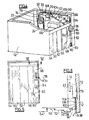
- FIG. 1 represents very schematically an elevator installation 10 according to the invention.
- the elevator installation comprises, in a manner known per se, a shaft 12 in which a cabin 14 moves vertically. comprises a floor 16, a roof 18 and a cabin door 20.
- the cabin is driven by an elevator machine, we have only shown the drive pulley 22 so as not to clutter the figure.
- the traction cables 24 are muffled on pulleys 26 mounted under the cab and on a counterweight, not represented.
- Figure 1 shows the cabin stopped at the last level, of which the bearing 28, the upper ceiling 31 and the door have been shown landing 32.
- the height H of the upper bearing is reduced to as low as about 2800 mm or even 2,600 mm, depending on cabin speed, while in installations traditional, this height is around 3,800 mm or 3,600 mm respectively. This is achieved thanks to the characteristics which will be explained below in detail.
- the maintenance operations are made from inside the cabin, through an opening 34 formed in the roof 18 of the cabin.
- the technician must climb on a stepladder 36 which is placed on the floor 16 of the cabin and make pass his body through opening 34 to waist height. This position already makes it possible to reduce the height of the upper level at least one meter compared to conventional installations where the technician stood on the roof of the cabin.
- the opening 34 is normally closed by a hatch 38 ( Figure 2) which is locked by means of an electric lock 40 which is can control from inside the cabin.
- a visit box 42 which is provided with a up button, down button and stop button. Thanks to this box, the technician can bring the cabin to the level of one electrical equipment, for example element 43, which are fixed in the sheath for inspection.
- the hatch 38 is provided on its edge which is adjacent to the housing visit of a vertical ledge 44 which hides said buttons when the hatch is in the closed position. The buttons cannot then be accidentally operated by a person who is break-in on the cabin roof through a landing door, without opening the hatch.
- a door operator 46 and a cabin slide 48 which are also within range of technician's hand.
- the cabin 14 is not mounted on a caliper, as is usual in elevator installations but it is directly suspended from the traction cables 24.
- the two vertical arms of the caliper are assembled on top from the roof of the cabin by crosspieces, themselves connected by reinforcements.
- These crosspieces and reinforcements are formed by profiles of metal several centimeters high.
- the standard provides that must maintain a safe distance between the roof of the cabin high position and the ceiling of the duct equal to approximately 500 mm. This distance must be counted from the crosspieces and reinforcements.
- the cabin according to the invention does not have a stirrup and therefore no cross members and reinforcements on its roof, the safety distance d will be counted from the upper surface of the roof, which is an additional reason for reducing the height H of the upper level.
- Figure 4 shows the landing door of the last level.
- This door landing includes two sliding leaves 50, 52 and two panels facade 54, 56 behind which the leaves retract when are in the open position. According to the invention, it is provided laterally at panel 56, an access gate 58 which is slidably mounted between an open position where it retracts behind said panel and thus discovers an opening 60 which gives on the inside of the sheath ( Figures 4 and 5) and a closed position where it closes said opening.
- the lower part of the opening 60 is permanently closed by a fixed protective plate 62 which serves to prevent any risk of falling objects or animals in the sheath.
- a fixed protective plate 62 which serves to prevent any risk of falling objects or animals in the sheath.
- an operating cabinet 64 which is slidably mounted horizontally from a position retracted where it is inside the sheath and an extended position where it is entirely on the landing.
- a fixed cabinet 66 containing the components that control the power cut.
- an elevator machine 68 is mounted on the fixed cabinet includes a motor 70 which drives a winch 72 provided with a pulley 22 and a brake 74. The machine is partially inserted inside a blind niche 76 built on the wall of the sheath, only part of its thickness extending beyond the niche into the space between the cabin and the wall of the sheath.
- a technician can access the two cabinets and the machine, from the landing through the open gate and can thus exit the sliding cabinet 64 so that it can be used from the landing, or cut the power in the event of a serious incident, or check the regulator speed or maneuver the elevator car in case it got stuck between two floors.
- niche 76 contributes also to facilitate the operation of hooking the connecting rod 100 to the shaft of the motor. Indeed, as shown in Figure 6, to maneuver the steering wheel without effort, it is desirable that the connecting rod 100 be parallel to the wall 105 of the sheath and either at the same short distance from said wall as the shaft 104.
- the niche 76 forecast allows to bring the axis of the shaft 104 closer to the wall 105 of the sheath.
- the gate 58 in sliding mode allows much simpler opening and gives greater security to installation compared to the case where the gate was removable.
- the gate can be opened in two stages: a time when we open the opening in order to access the buttons control cabinets and a second time when the gate retracts completely behind the panel 56 in order to clear the entire opening 60 to be able to extract the sliding cabinet 64.
Landscapes
- Engineering & Computer Science (AREA)
- Civil Engineering (AREA)
- Mechanical Engineering (AREA)
- Structural Engineering (AREA)
- Cage And Drive Apparatuses For Elevators (AREA)
- Types And Forms Of Lifts (AREA)
- Lift-Guide Devices, And Elevator Ropes And Cables (AREA)
Abstract
Description
La présente invention concerne une nouvelle conception d'installation d'ascenseur qui permet de réduire la hauteur entre le plafond de la gaine et le toit de la cabine, lorsque celle-ci est à l'arrêt au niveau supérieur.The present invention relates to a new design elevator installation which reduces the height between the ceiling of the sheath and the roof of the cabin, when the latter is stopped at higher level.
Actuellement, cette hauteur ne peut pas être réduite à moins de 3 400 à 3 600 mm selon la vitesse de la cabine, cette distance étant nécessaire pour permettre à un technicien de se tenir debout sur le toit de la cabine afin d'effectuer les opérations de maintenance sur les équipements électriques qui sont fixés sur le toit de la cabine ou dans la gaine, tout en gardant au-dessus de lui une distance de sécurité. Pour avoir une telle hauteur, il est nécessaire de construire un édicule sur la terrasse du bâtiment ou d'édifier un étage supplémentaire pour y loger les locaux techniques. Mais ces solutions sont naturellement fort coûteuses et portent atteinte à l'esthétique du bâtiment.Currently, this height cannot be reduced to less than 3,400 to 3,600 mm depending on the speed of the cabin, this distance being necessary to allow a technician to stand on the roof of the cabin in order to carry out maintenance operations on the electrical equipment which is fixed on the roof of the cabin or in the sheath, while keeping a safe distance above it. For have such a height, it is necessary to build a kiosk on the building terrace or build an additional floor to house it technical rooms. But these solutions are naturally strong expensive and affect the aesthetics of the building.
L'invention vise à remédier à cet inconvénient et propose une installation d'ascenseur ayant un certain nombre de caractéristiques techniques qui, associées entre elles, permettent de réduire de façon conséquente la hauteur du dernier niveau du bâtiment, tout en respectant la sécurité des usagers et des techniciens. Grâce à ces mesures, on peut réduire cette hauteur à environ 2 600 mm ou à environ 2 800 mm selon la vitesse de la cabine.The invention aims to remedy this drawback and proposes a elevator installation with a number of characteristics techniques which, when combined, make it possible to reduce consequent the height of the last level of the building, while respecting the safety of users and technicians. Thanks to these measures, this height can be reduced to around 2,600 mm or about 2800 mm depending on the speed of the cabin.
L'invention concerne donc une installation d'ascenseur pourvue d'un dernier niveau de hauteur réduite, ladite installation étant caractérisée en ce que la cabine présente sur son toit une trappe d'inspection à travers laquelle un technicien, monté sur un escabeau qui est posé sur le plancher de la cabine, peut faire passer son corps jusqu'à la taille, pour effectuer des opérations de maintenance, ladite trappe étant fermée pendant le service par des moyens de verrouillage, dont le déverrouillage peut être commandé depuis l'intérieur de la cabine.The invention therefore relates to an elevator installation provided a last level of reduced height, said installation being characterized in that the cabin has a hatch on its roof inspection through which a technician, mounted on a stepladder which is placed on the cabin floor, can pass its body up to the waist, to carry out maintenance operations, said hatch being closed during service by locking means, whose unlocking can be controlled from inside the cabin.
Sur ledit toit est fixée, à proximité d'un bord de la trappe d'inspection, une boíte de révision grâce à laquelle le technicien peut déplacer la cabine jusqu'à ce qu'il se mette au niveau de l'un ou l'autre des composants à inspecter fixés en gaine. Ladite trappe comporte une portion de masquage qui rend inaccessible la boíte de visite à une personne qui serait montée par infraction sur le toit de la cabine, à travers l'une des portes palières de l'installation.On said roof is fixed, near an edge of the hatch inspection, a revision box with which the technician can move the cabin until it is level with one or the other components to be inspected fixed in sheath. Said hatch includes a masking portion which makes the service box inaccessible to a person who is allegedly mounted on the roof of the cabin, through one of the landing doors of the installation.
Grâce à ces caractéristiques, il devient possible d'effectuer toutes les opérations de maintenance en opérant depuis l'intérieur de la cabine. Pour cette raison déjà, la hauteur du niveau supérieur du bâtiment peut être réduite d'au moins un mètre par rapport aux installations d'ascenseurs traditionnelles où le technicien devait monter sur le toit de la cabine.Thanks to these characteristics, it becomes possible to carry out all maintenance operations by operating from inside the cabin. For this reason already, the height of the upper level of the building can be reduced by at least one meter compared to traditional elevator installations where the technician had to climb on the roof of the cabin.
Selon les normes en vigueur, on doit garantir une distance de sécurité de 500 mm environ entre le plafond de la gaine et le toit de la cabine, lorsque celle-ci est à l'arrêt à son niveau supérieur. Plus exactement, cette distance est comptée à partir du sommet des éléments qui se trouvent sur le toit de la cabine. Par exemple, dans le cas des installations d'ascenseurs où la cabine est fixée dans un étrier ou arcade, la distance de sécurité doit être comptée à partir du sommet des traverses d'étrier et des renforts qui sont fixés sur le toit de la cabine. Afin de conserver ladite distance de sécurité, il est nécessaire de surélever le plafond de la gaine de la hauteur de ces traverses et renforts, ce qui augmente d'autant la hauteur du dernier niveau.According to the standards in force, a distance of security of about 500 mm between the duct ceiling and the roof of the cabin, when it is stopped at its upper level. More exactly, this distance is counted from the top of elements that are on the roof of the cabin. For example, in the case of elevator installations where the car is fixed in a stirrup or arcade, the safety distance must be counted from the top stirrup crosspieces and reinforcements which are fixed on the roof of the cabin. In order to maintain said safety distance, it is necessary to raise the ceiling of the duct by the height of these crosspieces and reinforcements, which further increases the height of the last level.
L'invention vise également à remédier à cet inconvénient et à cet effet, elle a pour objet une installation d'ascenseur dans laquelle la cabine n'est pas fixée dans un étrier, comme c'est le cas dans les ascenseurs classiques, mais est directement suspendue aux câbles de traction du système d'entraínement. Une telle cabine ne comporte plus sur son toit de traverses et de renforts, de sorte que la distance de sécurité peut être comptée à partir de la surface supérieure du toit. Ceci contribue à réduire également la hauteur du niveau supérieur.The invention also aims to remedy this drawback and this Indeed, it relates to an elevator installation in which the cabin is not fixed in a bracket, as is the case in conventional elevators but is directly suspended from the cables of traction system drive. Such a cabin no longer has on its roof of sleepers and reinforcements, so that the distance from security can be counted from the top surface of the roof. This also helps to reduce the height of the upper level.
De cette réduction de hauteur, découle encore un autre avantage important. L'accès à la machine de l'ascenseur qui se trouve à la partie la plus haute de la gaine, devient beaucoup plus aisé, car on peut désormais l'atteindre en se tenant debout sur le palier du dernier niveau, à travers une ouverture formée sur la façade de la porte palière, à hauteur d'homme. Au contraire, dans les installations d'ascenseurs traditionnelles où la hauteur du dernier niveau est de 3 800 mm, la machine ne peut être atteinte qu'en montant sur une échelle posée sur le palier.Yet another benefit from this reduction in height important. Access to the elevator machine located at the party the higher of the sheath becomes much easier, because we can now reach it by standing on the landing of the last level, through an opening formed on the front of the landing door, at breast height. On the contrary, in elevator installations where the height of the last level is 3,800 mm, the machine can only be reached by climbing a ladder on the landing.
Selon une autre caractéristique de l'invention, l'accès à la machine et aux différents équipements électriques qui sont montés à la partie supérieure de la gaine se fait à travers un portillon d'accès placé latéralement par rapport à la porte palière du dernier niveau. Avantageusement, ledit portillon est monté coulissant entre une position fermée où il obture une ouverture se trouvant en regard de la machine et des équipements électriques, et une position ouverte où il est escamoté derrière un panneau de façade de la porte palière et découvre ainsi ladite ouverture.According to another characteristic of the invention, access to the machine and to the various electrical equipments which are fitted to the part of the sheath is done through an access gate placed laterally in relation to the landing door of the last level. Advantageously, said gate is slidably mounted between a closed position where it closes an opening opposite the machine and electrical equipment, and an open position where it is retracted behind a front panel of the landing door and thus discovers said opening.
Par mesure de sécurité, à l'arrière du portillon est montée une plaque de protection qui, lorsque le portillon est ouvert, obstrue la partie inférieure de l'ouverture afin d'empêcher la chute accidentelle d'objets, la machine et les équipements électriques montés à la partie supérieure de la gaine pouvant être atteints à travers la partie découverte de l'ouverture.As a safety measure, at the rear of the gate is mounted a protective plate which, when the door is open, obstructs the lower part of the opening to prevent accidental falling of objects, the machine and the electrical equipment fitted to the part upper sheath can be reached through the part discovery of the opening.
Les équipements électriques comprennent une armoire de manoeuvre montée coulissante sur des rails horizontaux et qui peut donc être sortie hors de la gaine, à travers ladite ouverture, pour être amenée sur le palier du niveau supérieur et une armoire fixe contenant les composants qui commandent la coupure du courant.Electrical equipment includes a cabinet maneuver mounted sliding on horizontal rails and which can therefore be taken out of the sheath, through said opening, to be brought to the upper level landing and a fixed cabinet containing the components that control the power cut.
Avantageusement, l'armoire de manoeuvre est fixée sur la paroi de la gaine à un niveau juste supérieur à celui du bord supérieur de la plaque de protection, l'armoire fixe est fixée à un niveau supérieur à celui de l'armoire coulissante et la machine est fixée au-dessus du niveau de l'armoire fixe.Advantageously, the control cabinet is fixed to the wall of the sheath at a level just higher than that of the upper edge of the protective plate, the fixed cabinet is fixed at a level higher than that of the sliding cabinet and the machine is fixed above the fixed cabinet level.
De façon connue en soi, la machine comprend un treuil muni d'un frein et d'une poulie de traction autour de laquelle s'enroulent les câbles de traction. Afin de permettre le libre passage de brins verticaux des câbles de traction, la machine est fixée à l'arrière des deux armoires, et se trouve donc plus éloignée de l'ouverture que les armoires.In a manner known per se, the machine comprises a winch provided with a brake and a traction sheave around which the cables are wound traction. In order to allow the free passage of vertical strands of traction cables, the machine is fixed to the rear of the two cabinets, and is therefore further from the opening than the cupboards.
Cette implantation étagée facilite grandement les opérations de dépannage de secours en vue d'extraire les passagers de la cabine lorsque celle-ci est en panne entre deux étages. Ces opérations peuvent être effectuées depuis le dernier palier, portillon ouvert, ce qui permet d'accéder aux différentes possibilités de dépannage, de visualiser en permanence la position de la cabine et de maítriser la dérive de la cabine, comme on l'expliquera en détail par la suite.This layered layout greatly facilitates the operations of emergency breakdown assistance to extract passengers from the cabin when it is broken between two floors. These operations can be carried out from the last landing, gate open, which allows access the various troubleshooting possibilities, view permanently the position of the cabin and to control the drift of the cabin, as will be explained in detail later.
On décrira à présent plus en détail un mode de réalisation de
l'invention, à titre d'exemple non limitatif, en regard des dessins
annexés dans lesquels :
On se réfèrera tout d'abord à la figure 1 qui représente très
schématiquement une installation d'ascenseur 10 selon l'invention.
L'installation d'ascenseur comprend, de façon connue en soi, une gaine
12 dans laquelle se déplace verticalement une cabine 14. Celle-ci
comprend un plancher 16, un toit 18 et une porte de cabine 20. La
cabine est entraínée du mouvement par une machine d'ascenseur, dont
on n'a représenté que la poulie d'entraínement 22 pour ne pas
encombrer la figure. Les câbles de traction 24 sont moufflés sur des
poulies 26 montées sous la cabine et sur un contrepoids, non
représenté. La figure 1 montre la cabine à l'arrêt au dernier niveau,
dont on a représenté le palier 28, le plafond supérieur 31 et la porte
palière 32.We will first refer to Figure 1 which represents very
schematically an
Conformément à l'invention, la hauteur H du palier supérieur est réduite à une valeur aussi basse qu'environ 2 800 mm ou même 2 600 mm, selon la vitesse de la cabine, alors que dans les installations traditionnelles, cette hauteur est de l'ordre de 3 800 mm ou 3 600 mm respectivement. Ce résultat est obtenu grâce aux caractéristiques qui vont être expliquées ci-après en détail.According to the invention, the height H of the upper bearing is reduced to as low as about 2800 mm or even 2,600 mm, depending on cabin speed, while in installations traditional, this height is around 3,800 mm or 3,600 mm respectively. This is achieved thanks to the characteristics which will be explained below in detail.
Tout d'abord, selon l'invention, les opérations de maintenance sont
effectuées depuis l'intérieur de la cabine, à travers une ouverture 34
formée dans le toit 18 de la cabine. Pour cela, le technicien doit monter
sur un escabeau 36 qui est posé sur le plancher 16 de la cabine et faire
passer son corps à travers l'ouverture 34 jusqu'à hauteur de la taille.
Cette position permet déjà de réduire la hauteur du niveau supérieur
d'au moins un mètre par rapport aux installations classiques où le
technicien se mettait debout sur le toit de la cabine.First of all, according to the invention, the maintenance operations are
made from inside the cabin, through an
L'ouverture 34 est normalement obturée par une trappe 38
(figure 2) qui est verrouillée au moyen d'un verrou électrique 40 que l'on
peut commander depuis l'intérieur de la cabine. Le long de l'un des
bords de l'ouverture est fixé un boítier de visite 42 qui est muni d'un
bouton de montée, d'un bouton de descente et d'un bouton de stop.
Grâce à ce boítier, le technicien peut amener la cabine au niveau de l'un
des équipements électriques, par exemple l'élément 43, qui sont fixés
dans la gaine en vue de les inspecter.The opening 34 is normally closed by a hatch 38
(Figure 2) which is locked by means of an
La trappe 38 est munie sur son bord qui est adjacent au boítier de
visite d'un rebord vertical 44 qui vient masquer lesdits boutons lorsque
la trappe est en position fermée. Les boutons ne peuvent alors pas être
actionnés accidentellement par une personne qui serait montée par
effraction sur le toit de la cabine à travers une porte palière, sans ouvrir
la trappe.The
Sur le toit de la cabine sont également fixés un opérateur de porte
46 et un coulisseau de cabine 48 qui se trouvent également à portée de
la main du technicien.On the roof of the cabin are also fixed a
Comme le montre la figure 1, la cabine 14 n'est pas montée sur un
étrier, comme il est habituel dans les installations d'ascenseurs
classiques, mais elle est directement suspendue aux câbles de traction
24. On comprendra l'avantage apporté par cette caractéristique, dans le
cadre de l'idée de base de l'invention qui est de réduire la hauteur du
niveau supérieur, en rappelant que dans une cabine montée dans un
étrier, les deux bras verticaux de l'étrier sont assemblés sur le dessus
du toit de la cabine par des traverses, elles-mêmes reliées par des
renforts. Ces traverses et renforts sont constitués par des profilés
métalliques ayant plusieurs centimètres de hauteur. On rappelle
également que, pour des raisons de sécurité, la norme prévoit que l'on
doit maintenir une distance de sécurité entre le toit de la cabine en
position haute et le plafond de la gaine égale à environ 500 mm. Cette
distance doit être comptée à partir des traverses et renforts. As shown in Figure 1, the
Du fait que la cabine selon l'invention ne comporte pas d'étrier et donc pas de traverses et renforts sur son toit, la distance de sécurité d sera comptée à partir de la surface supérieure du toit, ce qui est une raison supplémentaire pour réduire la hauteur H du niveau supérieur.Since the cabin according to the invention does not have a stirrup and therefore no cross members and reinforcements on its roof, the safety distance d will be counted from the upper surface of the roof, which is an additional reason for reducing the height H of the upper level.
On se réfèrera à présent aux figures 4 à 6 qui illustrent d'autres avantages de l'installation de l'invention obtenus grâce à la réduction de la hauteur du dernier niveau.We will now refer to Figures 4 to 6 which illustrate other advantages of the installation of the invention obtained thanks to the reduction of the height of the last level.
La figure 4 montre la porte palière du dernier niveau. Cette porte
palière comprend deux vantaux coulissants 50, 52 et deux panneaux de
façade 54, 56 derrière lesquels les vantaux s'escamotent lorsqu'ils
sont en position ouverte. Selon l'invention, il est prévu latéralement
au panneau 56, un portillon d'accès 58 qui est monté coulissant
entre une position ouverte où il s'escamote derrière ledit panneau et
découvre ainsi une ouverture 60 qui donne sur l'intérieur de la gaine
(figures 4 et 5) et une position fermée où il obture ladite ouverture.Figure 4 shows the landing door of the last level. This door
landing includes two sliding
La partie inférieure de l'ouverture 60 est fermée en permanence
par une plaque de protection fixe 62 qui sert à empêcher tout risque de
chute d'objets ou d'animaux dans la gaine. Lorsque le portillon est
ouvert, seule la partie supérieure de l'ouverture située au-dessus de la
plaque de protection est découverte.The lower part of the
Sur la paroi de la gaine est fixée, légèrement au-dessus du bord
supérieur de la plaque de protection 62, une armoire de manoeuvre 64
qui est montée coulissante horizontalement depuis une position
rétractée où elle se trouve à l'intérieur de la gaine et une position sortie
où elle se trouve entièrement sur le palier. Légèrement au-dessus de
l'armoire de manoeuvre est fixée une armoire fixe 66 contenant les
composants qui commandent la coupure du courant. Encore au-dessus
de l'armoire fixe est montée une machine d'ascenseur 68. Celle-ci
comprend un moteur 70 qui entraíne un treuil 72 muni d'une poulie
d'entraínement 22 et d'un frein 74. La machine est partiellement insérée
à l'intérieur d'une niche borgne 76 construite sur la paroi de la gaine,
seule une partie de son épaisseur débordant hors de la niche dans
l'espace compris entre la cabine et la paroi de la gaine.On the wall of the sheath is fixed, slightly above the edge
upper of the
Grâce à la disposition étagée des armoires 64, 66 et de la machine
68, un technicien peut accéder aux deux armoires et à la machine,
depuis le palier à travers le portillon ouvert et peut ainsi faire sortir
l'armoire coulissante 64 pour qu'elle soit exploitable du palier, ou
couper le courant en cas d'incident grave, ou contrôler le régulateur de
vitesse ou encore manoeuvrer la cabine d'ascenseur dans le cas où elle
s'est bloquée entre deux étages.Thanks to the layered arrangement of
Selon la panne qui s'est produite, la manoeuvre du dépannage de
secours peut se faire selon l'une des trois procédures suivantes :
On comprend à présent que pour permettre l'utilisation du volant
de manoeuvre, il a fallu revoir la conception des armoires 64 et 66 et
leur disposition pour que la machine 68 soit accessible à travers
l'ouverture 60. Jusqu'à présent, ces armoires étaient volumineuses et
masquaient la machine pour un technicien se trouvant sur le palier. En
réduisant leur volume et en les fixant selon une disposition étagée, on
est arrivé à dégager un espace permettant de voir directement la
machine et de diriger l'extrémité de la bielle 100 pour l'accrocher sur
l'arbre du moteur.We now understand that to allow the use of the steering wheel
maneuver, it was necessary to review the design of
Il est clair également que c'est grâce au fait que la hauteur du
dernier niveau a été réduite que l'accès à l'arbre 104 du moteur peut se
faire en se tenant debout sur le palier, sans avoir à grimper sur une
échelle.It is also clear that it is thanks to the fact that the height of the
last level has been reduced as access to the
On peut encore dire que la présence de la niche 76 contribue
également à faciliter l'opération d'accrochage de la bielle 100 à l'arbre
du moteur. En effet, comme le montre la figure 6, pour manoeuvrer le
volant sans effort, il est souhaitable que la bielle 100 soit parallèle à la
paroi 105 de la gaine et soit à la même faible distance de ladite paroi
que l'arbre 104. Avantageusement, on peut s'aider à guider la bielle en
la faisant passer dans un ou deux anneaux 106 ouverts plantés sur la
paroi de la gaine et disposés de manière que l'axe de leur ouverture soit
confondu avec l'axe de dépannage. La prévision de la niche 76 permet
de rapprocher l'axe de l'arbre 104 de la paroi 105 de la gaine.We can also say that the presence of
Le montage du portillon 58 en mode coulissant permet une
ouverture beaucoup plus simple et confère une plus grande sécurité à
l'installation par rapport au cas où le portillon était démontable.
Avantageusement, l'ouverture du portillon peut se faire en deux temps :
un temps où l'on entrebâille l'ouverture afin d'accéder aux boutons de
commande des armoires et un second temps où le portillon s'escamote
entièrement derrière le panneau 56 afin de dégager toute l'ouverture 60
pour pouvoir extraire l'armoire coulissante 64.Mounting the
Claims (13)
Applications Claiming Priority (2)
| Application Number | Priority Date | Filing Date | Title |
|---|---|---|---|
| FR0009598 | 2000-07-21 | ||
| FR0009598A FR2811971B1 (en) | 2000-07-21 | 2000-07-21 | ELEVATOR INSTALLATION WITH A REDUCED HEIGHT UPPER LEVEL |
Publications (2)
| Publication Number | Publication Date |
|---|---|
| EP1174381A1 true EP1174381A1 (en) | 2002-01-23 |
| EP1174381B1 EP1174381B1 (en) | 2009-06-24 |
Family
ID=8852786
Family Applications (1)
| Application Number | Title | Priority Date | Filing Date |
|---|---|---|---|
| EP01401969A Expired - Lifetime EP1174381B1 (en) | 2000-07-21 | 2001-07-23 | Lift plant with an high reduced shaft head room |
Country Status (4)
| Country | Link |
|---|---|
| EP (1) | EP1174381B1 (en) |
| AT (1) | ATE434582T1 (en) |
| DE (1) | DE60139051D1 (en) |
| FR (1) | FR2811971B1 (en) |
Cited By (22)
| Publication number | Priority date | Publication date | Assignee | Title |
|---|---|---|---|---|
| FR2845074A1 (en) * | 2002-10-10 | 2004-04-02 | Otis Elevator Co | Trap door panel for enabling operator to service equipment mounted on lift roof, includes inspection and connection housings fixed to top face of panel which can pivot towards the interior of the elevator car |
| WO2004046010A1 (en) * | 2002-11-18 | 2004-06-03 | Inventio Ag | Elevator control unit integrated into a door jamb |
| WO2005026033A1 (en) * | 2003-09-15 | 2005-03-24 | Otis Elevator Company | Elevator inspection safety devices |
| US20080047783A1 (en) * | 2006-07-26 | 2008-02-28 | Wolfgang Vogl | Method of controlling access to an elevator car |
| WO2008074168A1 (en) * | 2006-12-20 | 2008-06-26 | H. Henseler Ag | Elevator car for reduced elevator hoistway tops |
| US7568557B2 (en) * | 2003-07-03 | 2009-08-04 | Inventio Ag | Elevator car with car electrical system integrated in the car roof and method of mounting an elevator installation |
| ITMI20091887A1 (en) * | 2009-10-29 | 2011-04-30 | Lenzi S P A | LIFTING SYSTEM WITH FACILITATED AND RELATIVE MAINTENANCE LIFT CABIN |
| US20120279805A1 (en) * | 2009-11-06 | 2012-11-08 | Aloys Wobben | Elevator |
| US20130220742A1 (en) * | 2010-10-11 | 2013-08-29 | Kone Corporation | Elevator |
| US8875845B2 (en) * | 2005-10-21 | 2014-11-04 | Alimak Ab | Safety arrangement for a lift car in a lift |
| WO2014191380A1 (en) * | 2013-05-28 | 2014-12-04 | Inventio Ag | Elevator shaft with reduced shaft pit or reduced shaft top |
| US20150075918A1 (en) * | 2013-09-17 | 2015-03-19 | Kone Corporation | Elevator |
| EP3000760A1 (en) * | 2014-07-30 | 2016-03-30 | Orona, S. Coop. | Elevator apparatus |
| WO2016162713A1 (en) * | 2015-04-07 | 2016-10-13 | Otis Elevator Company | Accessible elevator buffer |
| CN106185522A (en) * | 2016-08-19 | 2016-12-07 | 卢碧娴 | Escape device on elevator |
| WO2018011460A1 (en) * | 2016-07-15 | 2018-01-18 | Kone Corporation | Elevator arrangement |
| WO2018011461A1 (en) * | 2016-07-15 | 2018-01-18 | Kone Corporation | Elevator arrangement with low headroom |
| CN109476456A (en) * | 2016-07-15 | 2019-03-15 | 通力股份公司 | Lift appliance and elevator |
| CN109476460A (en) * | 2016-07-15 | 2019-03-15 | 通力股份公司 | Lift appliance for security maintenance work |
| US20200277163A1 (en) * | 2019-03-01 | 2020-09-03 | Otis Elevator Company | Controlling movement of an elevator car |
| US11498811B2 (en) | 2018-04-27 | 2022-11-15 | Otis Elevator Company | Elevator display systems |
| US11560291B2 (en) * | 2016-07-15 | 2023-01-24 | Kone Corporation | Elevator arrangement to open the roof of an elevator car |
Families Citing this family (1)
| Publication number | Priority date | Publication date | Assignee | Title |
|---|---|---|---|---|
| EP3530603B1 (en) | 2018-02-27 | 2022-08-10 | Otis Elevator Company | Elevator car comprising a working platform and method of moving a working platform |
Citations (4)
| Publication number | Priority date | Publication date | Assignee | Title |
|---|---|---|---|---|
| US4043430A (en) * | 1975-08-28 | 1977-08-23 | Westinghouse Electric Corporation | Elevator system having common enclosure for open wiring between door controls, car top inspection station controls and traveling cable |
| EP0870722A1 (en) * | 1997-04-10 | 1998-10-14 | Inventio Ag | Maintenance apparatus for elevator car |
| WO1999043596A2 (en) * | 1998-02-26 | 1999-09-02 | Otis Elevator Company | Elevator system having drive motor located adjacent to hoistway door |
| US5971109A (en) * | 1996-09-05 | 1999-10-26 | Kone Oy | Arrangement for releasing the brake of an elevator machinery |
-
2000
- 2000-07-21 FR FR0009598A patent/FR2811971B1/en not_active Expired - Fee Related
-
2001
- 2001-07-23 DE DE60139051T patent/DE60139051D1/en not_active Expired - Lifetime
- 2001-07-23 EP EP01401969A patent/EP1174381B1/en not_active Expired - Lifetime
- 2001-07-23 AT AT01401969T patent/ATE434582T1/en not_active IP Right Cessation
Patent Citations (4)
| Publication number | Priority date | Publication date | Assignee | Title |
|---|---|---|---|---|
| US4043430A (en) * | 1975-08-28 | 1977-08-23 | Westinghouse Electric Corporation | Elevator system having common enclosure for open wiring between door controls, car top inspection station controls and traveling cable |
| US5971109A (en) * | 1996-09-05 | 1999-10-26 | Kone Oy | Arrangement for releasing the brake of an elevator machinery |
| EP0870722A1 (en) * | 1997-04-10 | 1998-10-14 | Inventio Ag | Maintenance apparatus for elevator car |
| WO1999043596A2 (en) * | 1998-02-26 | 1999-09-02 | Otis Elevator Company | Elevator system having drive motor located adjacent to hoistway door |
Cited By (34)
| Publication number | Priority date | Publication date | Assignee | Title |
|---|---|---|---|---|
| FR2845074A1 (en) * | 2002-10-10 | 2004-04-02 | Otis Elevator Co | Trap door panel for enabling operator to service equipment mounted on lift roof, includes inspection and connection housings fixed to top face of panel which can pivot towards the interior of the elevator car |
| US7398861B2 (en) | 2002-11-18 | 2008-07-15 | Inventio Ag | Elevator monitoring unit and procedure for the maintenance of an elevator unit |
| WO2004046010A1 (en) * | 2002-11-18 | 2004-06-03 | Inventio Ag | Elevator control unit integrated into a door jamb |
| US7568557B2 (en) * | 2003-07-03 | 2009-08-04 | Inventio Ag | Elevator car with car electrical system integrated in the car roof and method of mounting an elevator installation |
| US7281609B2 (en) | 2003-09-15 | 2007-10-16 | Otis Elevator Company | Elevator inspection safety devices |
| WO2005026033A1 (en) * | 2003-09-15 | 2005-03-24 | Otis Elevator Company | Elevator inspection safety devices |
| US8875845B2 (en) * | 2005-10-21 | 2014-11-04 | Alimak Ab | Safety arrangement for a lift car in a lift |
| US20080047783A1 (en) * | 2006-07-26 | 2008-02-28 | Wolfgang Vogl | Method of controlling access to an elevator car |
| US8602171B2 (en) * | 2006-07-26 | 2013-12-10 | Inventio Ag | Method of controlling access to an elevator car |
| WO2008074168A1 (en) * | 2006-12-20 | 2008-06-26 | H. Henseler Ag | Elevator car for reduced elevator hoistway tops |
| ITMI20091887A1 (en) * | 2009-10-29 | 2011-04-30 | Lenzi S P A | LIFTING SYSTEM WITH FACILITATED AND RELATIVE MAINTENANCE LIFT CABIN |
| EP2316774A1 (en) * | 2009-10-29 | 2011-05-04 | Lenzi S.p.A. | Elevator cabin |
| US20120279805A1 (en) * | 2009-11-06 | 2012-11-08 | Aloys Wobben | Elevator |
| US9260274B2 (en) * | 2009-11-06 | 2016-02-16 | Aloys Wobben | Lift for a wind power installation |
| US20130220742A1 (en) * | 2010-10-11 | 2013-08-29 | Kone Corporation | Elevator |
| CN105307964A (en) * | 2013-05-28 | 2016-02-03 | 因温特奥股份公司 | Elevator shaft with reduced shaft pit or reduced shaft top |
| WO2014191380A1 (en) * | 2013-05-28 | 2014-12-04 | Inventio Ag | Elevator shaft with reduced shaft pit or reduced shaft top |
| US20150075918A1 (en) * | 2013-09-17 | 2015-03-19 | Kone Corporation | Elevator |
| US10322907B2 (en) * | 2013-09-17 | 2019-06-18 | Kone Corporation | Elevator |
| EP3000760A1 (en) * | 2014-07-30 | 2016-03-30 | Orona, S. Coop. | Elevator apparatus |
| WO2016162713A1 (en) * | 2015-04-07 | 2016-10-13 | Otis Elevator Company | Accessible elevator buffer |
| CN109476460A (en) * | 2016-07-15 | 2019-03-15 | 通力股份公司 | Lift appliance for security maintenance work |
| WO2018011463A1 (en) * | 2016-07-15 | 2018-01-18 | Kone Corporation | Elevator arrangement |
| WO2018011461A1 (en) * | 2016-07-15 | 2018-01-18 | Kone Corporation | Elevator arrangement with low headroom |
| CN109476462A (en) * | 2016-07-15 | 2019-03-15 | 通力股份公司 | Lift appliance |
| CN109476456A (en) * | 2016-07-15 | 2019-03-15 | 通力股份公司 | Lift appliance and elevator |
| CN109476459A (en) * | 2016-07-15 | 2019-03-15 | 通力股份公司 | Lift appliance |
| CN109476461A (en) * | 2016-07-15 | 2019-03-15 | 通力股份公司 | Lift appliance with low clearance |
| WO2018011460A1 (en) * | 2016-07-15 | 2018-01-18 | Kone Corporation | Elevator arrangement |
| CN109476462B (en) * | 2016-07-15 | 2021-07-30 | 通力股份公司 | Elevator device |
| US11560291B2 (en) * | 2016-07-15 | 2023-01-24 | Kone Corporation | Elevator arrangement to open the roof of an elevator car |
| CN106185522A (en) * | 2016-08-19 | 2016-12-07 | 卢碧娴 | Escape device on elevator |
| US11498811B2 (en) | 2018-04-27 | 2022-11-15 | Otis Elevator Company | Elevator display systems |
| US20200277163A1 (en) * | 2019-03-01 | 2020-09-03 | Otis Elevator Company | Controlling movement of an elevator car |
Also Published As
| Publication number | Publication date |
|---|---|
| FR2811971B1 (en) | 2002-12-13 |
| FR2811971A1 (en) | 2002-01-25 |
| EP1174381B1 (en) | 2009-06-24 |
| ATE434582T1 (en) | 2009-07-15 |
| DE60139051D1 (en) | 2009-08-06 |
Similar Documents
| Publication | Publication Date | Title |
|---|---|---|
| EP1174381B1 (en) | Lift plant with an high reduced shaft head room | |
| EP0181268B1 (en) | Security and emergency operating mechanism for a folding door | |
| US20080060874A1 (en) | Automatic ladder for attic access | |
| EP0151076B1 (en) | Device for preventing access to derrick ladders | |
| US7428800B1 (en) | In-ground shelter | |
| FR2675196A1 (en) | EMERGENCY LADDER WITH BUILT-IN ELEVATOR. | |
| WO2008071868A2 (en) | Human-powered vertical lift basket | |
| FR2891820A1 (en) | Lift cabin has deployable guard rail and supple side panels to protect technicians working on cabin roof | |
| CH671757A5 (en) | ||
| FR2866665A1 (en) | Guardrail type safety device, has control unit controlling jack type linear actuator to move and maintain retaining unit in deployed position and to restore unit in retracted position, and net stretching across device in deployed position | |
| FR2713273A1 (en) | Roller shutter arrangement with protective mesh against insects. | |
| EP1030028B1 (en) | Fall protection device for a vertically movable closure | |
| FR2491120A1 (en) | Oven door seal clip - has resilient body which pierces seal and locates over wire attached to internal seal surface | |
| FR2933967A1 (en) | Carriage motorizing machine for working or accessing in e.g. high place, has left and right clutch mounted on shaft, where each clutch acts on setting of movement of left mechanic system and right mechanic system | |
| EP1197467A1 (en) | Device for locking an elevator landing door | |
| FR2744756A1 (en) | Sliding armoured door for building | |
| FR2667305A1 (en) | Large width goods lift | |
| FR2508532A1 (en) | Security counter for post office - comprises box with doors at each end which cannot open simultaneously | |
| EP0258919B1 (en) | Device for making access possible in a building to an exit closed by a trap door | |
| FR2871189A1 (en) | Up and over door driving mechanism for garage, has transmission with drive gear in output shaft of gear motors actuating counter-driven gear and coupling motors with rotation axle for operating blanking panel and control box of motors | |
| WO1990015219A1 (en) | Safety device for access to a ladder from an upper floor | |
| AU2005100513A4 (en) | Domestic Upper Floor Fire Escape | |
| EP0918035A1 (en) | Elevator plant with a control cabinet integrated within the shaft | |
| FR2930535A1 (en) | Mobile machinery i.e. gearless machine, for lift in existing building, has hook fixed in upper crosshead of clip, where machinery is integrated with longerons of clip, dissembled below floor pan of cabin and is accessible by opening of flap | |
| FR3093639A1 (en) | ROTARY LIFT DEVICE FOR PEOPLE WITH REDUCED MOBILITY |
Legal Events
| Date | Code | Title | Description |
|---|---|---|---|
| PUAI | Public reference made under article 153(3) epc to a published international application that has entered the european phase |
Free format text: ORIGINAL CODE: 0009012 |
|
| AK | Designated contracting states |
Kind code of ref document: A1 Designated state(s): AT BE CH CY DE DK ES FI FR GB GR IE IT LI LU MC NL PT SE TR |
|
| AX | Request for extension of the european patent |
Free format text: AL;LT;LV;MK;RO;SI |
|
| 17P | Request for examination filed |
Effective date: 20020701 |
|
| AKX | Designation fees paid |
Free format text: AT BE CH CY DE DK ES FI FR GB GR IE IT LI LU MC NL PT SE TR |
|
| 17Q | First examination report despatched |
Effective date: 20061205 |
|
| GRAP | Despatch of communication of intention to grant a patent |
Free format text: ORIGINAL CODE: EPIDOSNIGR1 |
|
| GRAS | Grant fee paid |
Free format text: ORIGINAL CODE: EPIDOSNIGR3 |
|
| GRAA | (expected) grant |
Free format text: ORIGINAL CODE: 0009210 |
|
| AK | Designated contracting states |
Kind code of ref document: B1 Designated state(s): AT BE CH CY DE DK ES FI FR GB GR IE IT LI LU MC NL PT SE TR |
|
| REG | Reference to a national code |
Ref country code: GB Ref legal event code: FG4D Free format text: NOT ENGLISH |
|
| REG | Reference to a national code |
Ref country code: CH Ref legal event code: EP |
|
| REG | Reference to a national code |
Ref country code: IE Ref legal event code: FG4D Free format text: LANGUAGE OF EP DOCUMENT: FRENCH |
|
| REF | Corresponds to: |
Ref document number: 60139051 Country of ref document: DE Date of ref document: 20090806 Kind code of ref document: P |
|
| PG25 | Lapsed in a contracting state [announced via postgrant information from national office to epo] |
Ref country code: FI Free format text: LAPSE BECAUSE OF FAILURE TO SUBMIT A TRANSLATION OF THE DESCRIPTION OR TO PAY THE FEE WITHIN THE PRESCRIBED TIME-LIMIT Effective date: 20090624 Ref country code: AT Free format text: LAPSE BECAUSE OF FAILURE TO SUBMIT A TRANSLATION OF THE DESCRIPTION OR TO PAY THE FEE WITHIN THE PRESCRIBED TIME-LIMIT Effective date: 20090624 |
|
| PG25 | Lapsed in a contracting state [announced via postgrant information from national office to epo] |
Ref country code: SE Free format text: LAPSE BECAUSE OF FAILURE TO SUBMIT A TRANSLATION OF THE DESCRIPTION OR TO PAY THE FEE WITHIN THE PRESCRIBED TIME-LIMIT Effective date: 20090924 |
|
| NLV1 | Nl: lapsed or annulled due to failure to fulfill the requirements of art. 29p and 29m of the patents act | ||
| PG25 | Lapsed in a contracting state [announced via postgrant information from national office to epo] |
Ref country code: ES Free format text: LAPSE BECAUSE OF FAILURE TO SUBMIT A TRANSLATION OF THE DESCRIPTION OR TO PAY THE FEE WITHIN THE PRESCRIBED TIME-LIMIT Effective date: 20091005 |
|
| REG | Reference to a national code |
Ref country code: IE Ref legal event code: FD4D |
|
| PG25 | Lapsed in a contracting state [announced via postgrant information from national office to epo] |
Ref country code: NL Free format text: LAPSE BECAUSE OF FAILURE TO SUBMIT A TRANSLATION OF THE DESCRIPTION OR TO PAY THE FEE WITHIN THE PRESCRIBED TIME-LIMIT Effective date: 20090624 |
|
| REG | Reference to a national code |
Ref country code: CH Ref legal event code: PL |
|
| PG25 | Lapsed in a contracting state [announced via postgrant information from national office to epo] |
Ref country code: PT Free format text: LAPSE BECAUSE OF FAILURE TO SUBMIT A TRANSLATION OF THE DESCRIPTION OR TO PAY THE FEE WITHIN THE PRESCRIBED TIME-LIMIT Effective date: 20091024 |
|
| PG25 | Lapsed in a contracting state [announced via postgrant information from national office to epo] |
Ref country code: LI Free format text: LAPSE BECAUSE OF NON-PAYMENT OF DUE FEES Effective date: 20090731 Ref country code: IE Free format text: LAPSE BECAUSE OF FAILURE TO SUBMIT A TRANSLATION OF THE DESCRIPTION OR TO PAY THE FEE WITHIN THE PRESCRIBED TIME-LIMIT Effective date: 20090624 Ref country code: DK Free format text: LAPSE BECAUSE OF FAILURE TO SUBMIT A TRANSLATION OF THE DESCRIPTION OR TO PAY THE FEE WITHIN THE PRESCRIBED TIME-LIMIT Effective date: 20090624 Ref country code: CH Free format text: LAPSE BECAUSE OF NON-PAYMENT OF DUE FEES Effective date: 20090731 |
|
| PLBE | No opposition filed within time limit |
Free format text: ORIGINAL CODE: 0009261 |
|
| REG | Reference to a national code |
Ref country code: CH Ref legal event code: NV Representative=s name: FREI PATENTANWALTSBUERO AG Ref country code: CH Ref legal event code: AEN Free format text: LE BREVET A ETE REACTIVE SELON LA DEMANDE DE POURSUITE DE LA PROCEDURE DU 26.03.2010. |
|
| STAA | Information on the status of an ep patent application or granted ep patent |
Free format text: STATUS: NO OPPOSITION FILED WITHIN TIME LIMIT |
|
| 26N | No opposition filed |
Effective date: 20100325 |
|
| PGRI | Patent reinstated in contracting state [announced from national office to epo] |
Ref country code: CH Effective date: 20100326 |
|
| PG25 | Lapsed in a contracting state [announced via postgrant information from national office to epo] |
Ref country code: GR Free format text: LAPSE BECAUSE OF FAILURE TO SUBMIT A TRANSLATION OF THE DESCRIPTION OR TO PAY THE FEE WITHIN THE PRESCRIBED TIME-LIMIT Effective date: 20090925 |
|
| PG25 | Lapsed in a contracting state [announced via postgrant information from national office to epo] |
Ref country code: IT Free format text: LAPSE BECAUSE OF FAILURE TO SUBMIT A TRANSLATION OF THE DESCRIPTION OR TO PAY THE FEE WITHIN THE PRESCRIBED TIME-LIMIT Effective date: 20090624 |
|
| PG25 | Lapsed in a contracting state [announced via postgrant information from national office to epo] |
Ref country code: TR Free format text: LAPSE BECAUSE OF FAILURE TO SUBMIT A TRANSLATION OF THE DESCRIPTION OR TO PAY THE FEE WITHIN THE PRESCRIBED TIME-LIMIT Effective date: 20090624 |
|
| PG25 | Lapsed in a contracting state [announced via postgrant information from national office to epo] |
Ref country code: CY Free format text: LAPSE BECAUSE OF FAILURE TO SUBMIT A TRANSLATION OF THE DESCRIPTION OR TO PAY THE FEE WITHIN THE PRESCRIBED TIME-LIMIT Effective date: 20090624 |
|
| REG | Reference to a national code |
Ref country code: FR Ref legal event code: PLFP Year of fee payment: 16 |
|
| REG | Reference to a national code |
Ref country code: FR Ref legal event code: PLFP Year of fee payment: 17 |
|
| REG | Reference to a national code |
Ref country code: FR Ref legal event code: PLFP Year of fee payment: 18 |
|
| REG | Reference to a national code |
Ref country code: CH Ref legal event code: PCAR Free format text: NEW ADDRESS: POSTFACH, 8032 ZUERICH (CH) |
|
| PGFP | Annual fee paid to national office [announced via postgrant information from national office to epo] |
Ref country code: FR Payment date: 20200626 Year of fee payment: 20 |
|
| PGFP | Annual fee paid to national office [announced via postgrant information from national office to epo] |
Ref country code: LU Payment date: 20200721 Year of fee payment: 20 Ref country code: GB Payment date: 20200727 Year of fee payment: 20 Ref country code: DE Payment date: 20200721 Year of fee payment: 20 Ref country code: MC Payment date: 20200723 Year of fee payment: 20 |
|
| PGFP | Annual fee paid to national office [announced via postgrant information from national office to epo] |
Ref country code: BE Payment date: 20200727 Year of fee payment: 20 Ref country code: CH Payment date: 20200721 Year of fee payment: 20 |
|
| REG | Reference to a national code |
Ref country code: DE Ref legal event code: R071 Ref document number: 60139051 Country of ref document: DE |
|
| REG | Reference to a national code |
Ref country code: CH Ref legal event code: PL |
|
| REG | Reference to a national code |
Ref country code: GB Ref legal event code: PE20 Expiry date: 20210722 |
|
| REG | Reference to a national code |
Ref country code: BE Ref legal event code: MK Effective date: 20210723 |
|
| PG25 | Lapsed in a contracting state [announced via postgrant information from national office to epo] |
Ref country code: GB Free format text: LAPSE BECAUSE OF EXPIRATION OF PROTECTION Effective date: 20210722 |