JP2015160661A - Tank device - Google Patents
Tank device Download PDFInfo
- Publication number
- JP2015160661A JP2015160661A JP2014038887A JP2014038887A JP2015160661A JP 2015160661 A JP2015160661 A JP 2015160661A JP 2014038887 A JP2014038887 A JP 2014038887A JP 2014038887 A JP2014038887 A JP 2014038887A JP 2015160661 A JP2015160661 A JP 2015160661A
- Authority
- JP
- Japan
- Prior art keywords
- pipe
- tank
- switching valve
- discharge port
- liquid
- Prior art date
- Legal status (The legal status is an assumption and is not a legal conclusion. Google has not performed a legal analysis and makes no representation as to the accuracy of the status listed.)
- Granted
Links
Images
Landscapes
- Loading And Unloading Of Fuel Tanks Or Ships (AREA)
Abstract
Description
本発明は、ガソリンや灯油等の液体燃料やその他の液体の運搬を行うタンクローリ等に設置されるタンク装置に関するものであり、詳しくは荷卸しの際にタンクに連結された荷卸し用の配管内に残液が生じることを抑制するタンク装置に関するものである。 The present invention relates to a tank apparatus installed in a tank lorry or the like for transporting liquid fuel such as gasoline or kerosene and other liquids, and more specifically, in an unloading pipe connected to a tank at the time of unloading. The present invention relates to a tank device that suppresses the generation of residual liquid.
製油所からガソリンスタンドへのガソリンや灯油等の液体燃料の運搬に、タンクローリ等が利用されている。このタンクローリは、内部を隔離壁により複数の液体貯蔵室に分割されたタンクと、このタンク外側でタンク底部に配置された主搬送管と、主搬送管から分岐され各液体貯蔵室にそれぞれ連結される複数の枝管と、主搬送管から分岐されタンク外側のタンク左右両側側方にそれぞれ延設される左配管および右配管(以下、総称する場合は左右配管という)とを有している。 Tank trucks are used to transport liquid fuels such as gasoline and kerosene from refineries to gas stations. The tank lorry is divided into a plurality of liquid storage chambers by an isolation wall inside, a main transfer pipe arranged at the bottom of the tank outside the tank, and branched from the main transfer pipe and connected to each liquid storage chamber. A plurality of branch pipes, and a left pipe and a right pipe (hereinafter collectively referred to as left and right pipes) branched from the main transfer pipe and extending to the left and right sides of the tank outside the tank.
荷卸しの際には、例えば左配管の端部の吐出し口とガソリンスタンドに設置されたガソリン貯蔵タンクとをホースで連結して、その後、タンクを構成する液体貯蔵室であってガソリンを貯蔵した液体貯蔵室の底弁を開放して、液体貯蔵室から枝管と主搬送管と左配管とを経由させてガソリン貯蔵タンクにガソリンを送る。続けて灯油を荷卸しする場合には、左配管の端部の吐出し口とガソリンスタンドに設置された灯油貯蔵タンクとをホースで連結して、タンクを構成する液体貯蔵室であって灯油を貯蔵した液体貯蔵室からの荷卸しを行う。 When unloading, for example, the discharge port at the end of the left pipe is connected to the gasoline storage tank installed at the gas station with a hose, and then the gasoline is stored in the liquid storage chamber that constitutes the tank. The bottom valve of the liquid storage chamber is opened, and gasoline is sent from the liquid storage chamber to the gasoline storage tank via the branch pipe, the main transfer pipe, and the left pipe. When unloading kerosene continuously, the discharge port at the end of the left pipe and the kerosene storage tank installed at the gas station are connected by a hose, and the kerosene is a liquid storage chamber constituting the tank. Unload from the stored liquid storage room.
このとき、ガソリンスタンドの地面が傾斜している等の理由によりタンクローリが傾斜している場合、左右配管や主搬送管内に先に荷卸ししたガソリンが残ってしまうことがある。この左右配管等の内部に残ったガソリン(以下、残液という)は、灯油を荷卸しする際にこの灯油と混ざってしまう。ガソリンの混ざった灯油は引火点が下がってしまい、この引火点が法令基準値を下回るとガソリンスタンドはこの灯油を販売することができなくなる。 At this time, if the tank truck is tilted due to the ground of the gasoline station being tilted or the like, the previously unloaded gasoline may remain in the left and right pipes or the main transport pipe. Gasoline remaining in the left and right pipes (hereinafter referred to as residual liquid) is mixed with kerosene when unloading kerosene. The kerosene mixed with gasoline has its flash point lowered, and if this flash point falls below the legal standard value, the gas station cannot sell the kerosene.
そのため、タンクローリによる荷卸しの際には残液の処理が行われていた(例えば特許文献1参照)。特許文献1で提案されているタンクローリの荷卸しシステムでは、残液の処理が完了したことを検出した後でなければ、次の液体燃料の荷卸しを開始できない。これにより、異種の液体燃料が混ざることを防止するものである。 For this reason, when the tank truck is unloaded, the residual liquid is processed (see, for example, Patent Document 1). In the tank truck unloading system proposed in Patent Document 1, the next liquid fuel unloading cannot be started unless it is detected that the processing of the remaining liquid has been completed. This prevents different types of liquid fuel from being mixed.
この荷卸しシステムは、残液の発生自体を防止できないため、荷卸しを行う作業者は荷卸しする油種が変わるたびに残液の処理を行わなくてはならなかった。この残液処理は、残液が発生している箇所近傍の弁を開放して残液を容器に回収して、その後この残液をタンク上部の開口部からタンク内に戻さなければならないため、作業者にとって煩雑なものであり負担が大きいものであった。左右配管や主搬送管の中途部など回収が困難な場所に残液が発生した場合は、この残液処理は作業者にとって更に負担の大きいものとなっていた。 Since this unloading system cannot prevent the generation of the remaining liquid itself, the worker performing unloading has to process the remaining liquid every time the oil type to be unloaded changes. In this residual liquid treatment, the valve near the location where the residual liquid is generated is opened to collect the residual liquid in a container, and then this residual liquid must be returned to the tank from the opening at the top of the tank. It was cumbersome and burdensome for the operator. When residual liquid is generated in places where recovery is difficult, such as in the middle of the left and right pipes and the main transfer pipe, this residual liquid processing has been a further burden on the operator.
また残液の有無を検知するためのセンサーが設置されていない箇所で残液が発生した場合には、残液の存在が認知されず残液処理が行われないため、異種の液体燃料が混ざってしまうことを防止できなかった。 Also, if residual liquid is generated at a location where a sensor for detecting the presence of residual liquid is not installed, the presence of the residual liquid is not recognized and the residual liquid treatment is not performed, so different types of liquid fuel are mixed. Could not be prevented.
本発明は上記の問題を鑑みてなされたものであり、その目的は車両とともに移動するタンク装置から荷卸しをする際に、タンクに連結された左右配管や主搬送管等の配管内に残液が生じることを抑制することで、異種の液体の混合を防止し、荷卸しを行う作業者の作業負担を軽減できるタンク装置を提供することである。 The present invention has been made in view of the above problems, and its purpose is to carry out residual liquid in pipes such as left and right pipes and main transfer pipes connected to the tank when unloading from a tank device that moves with the vehicle. It is an object of the present invention to provide a tank device that can prevent the mixing of different types of liquids and reduce the work load on an operator who performs unloading by suppressing the occurrence of liquid.
上記の目的を達成するための本発明のタンク装置は、内部を隔離壁により複数の液体貯蔵室に分割されたタンクと、このタンク外側でタンク底部に配置されてタンク前後方向に延設された主搬送管と、この主搬送管から分岐してそれぞれの液体貯蔵室の底弁に連結された複数の枝管と、前記主搬送管から分岐して前記タンク外側のタンク左右両側側方に配置されたそれぞれの側方吐出し口に連結された左配管および右配管とを備えた、車両とともに移動するタンク装置において、前記左配管および右配管は、それぞれの一端が前記主搬送管との分岐部分に設置された切換弁に連結され、それぞれの他端が前記側方吐出し口のうちの同じ側に設けられた側方吐出し口に連結され、前記切換弁から前記側方吐出し口に向かって下方に傾斜した状態で延設され、前記切換弁は、前記主搬送管とこの切換弁に連結された他のいずれか1つの配管とを選択的に連通させる構成を備えたことを特徴とする。 In order to achieve the above object, a tank apparatus according to the present invention includes a tank whose interior is divided into a plurality of liquid storage chambers by separating walls, and is disposed outside the tank at the bottom of the tank and extends in the front-rear direction of the tank. A main transfer pipe, a plurality of branch pipes branched from the main transfer pipe and connected to the bottom valves of the respective liquid storage chambers, and branched from the main transfer pipe and arranged on the left and right sides of the tank outside the tank In the tank apparatus that moves with the vehicle, including a left pipe and a right pipe connected to each of the lateral discharge ports, the left pipe and the right pipe each branch at one end from the main transport pipe The other end is connected to a side discharge port provided on the same side of the side discharge ports, and the side discharge port is connected to the changeover valve. Inclined downward toward Extends, said switching valve is characterized by having a configuration in which the said main conveying pipe of any one the changeover valve other connected to the pipe selectively communicating.
本発明によれば、タンク装置を搭載した車両(タンクローリ等)が左右に傾いている場合であっても、荷卸しに使用しない側の左配管または右配管を切換弁により閉止できるので、荷卸しに使用しない側の左配管または右配管に液体が流れ込んで残液となることを防止できる。また左配管および右配管(左右配管)は切換弁から吐出し口に向かって下り傾斜になっているので、タンクローリ等が左右に傾いていたとしても荷卸しに使用する側の左右配管の下り傾斜を維持し易くなり、この左右配管内に残液が発生することも抑制できる。 According to the present invention, even when a vehicle (tank lorry or the like) equipped with a tank device is tilted to the left or right, the left piping or the right piping on the side not used for unloading can be closed by the switching valve. It is possible to prevent the liquid from flowing into the left pipe or the right pipe on the side not used for the remaining liquid. The left and right pipes (left and right pipes) are inclined downward from the switching valve toward the discharge port, so even if the tank lorry is inclined to the left or right, the left and right pipes on the side used for unloading are inclined downward. It is easy to maintain and it is also possible to suppress the occurrence of residual liquid in the left and right pipes.
そのため、異種の液体が荷卸しの過程で混ざることを防止できる。また、従来のような面倒な残液処理が不要となるので、荷卸しを行う作業者の作業負担を大幅に低減することができる。 Therefore, it is possible to prevent different kinds of liquids from being mixed in the unloading process. In addition, since the troublesome residual liquid processing as in the prior art is not required, it is possible to greatly reduce the work load on the operator who performs unloading.
ここでたとえば、一端が切換弁に連結され、他端がタンク外側でタンク後方に配置された後方吐出し口に連結されて、切換弁から後方吐出し口に向かって下方に傾斜した状態で延設された後方配管を備えた構成にすることもできる。 Here, for example, one end is connected to the switching valve, the other end is connected to a rear discharge port disposed outside the tank and behind the tank, and extends in a state of being inclined downward from the switching valve toward the rear discharge port. It can also be set as the structure provided with the back piping provided.
この構成によれば、後方から荷卸しをする際に、主搬送管と後方配管のみを連通させて左右配管のいずれも切換弁により閉止できるので、荷卸しに使用しない左右配管に液体が流れ込んで残液となることを防止できる。また側方から荷卸しをする際に、荷卸しに使用しない後方配管を切換弁により閉止できるので、後方配管に液体が流れ込んで残液となることを防止できる。 According to this configuration, when unloading from the rear, only the main transfer pipe and the rear pipe are communicated and both the left and right pipes can be closed by the switching valve, so that liquid flows into the left and right pipes that are not used for unloading. It can prevent remaining liquid. In addition, when unloading from the side, the rear pipe that is not used for unloading can be closed by the switching valve, so that it is possible to prevent liquid from flowing into the rear pipe and becoming residual liquid.
切換弁が四方弁であり、左配管または右配管のいずれか一方の配管と、主搬送管と、後方管とがそれぞれ、切換弁の異なる側面に連結され、左配管または右配管のいずれか他方の配管が切換弁の底面に連結された構成にすることもできる。左右配管に比べて長くなる後方配管を切換弁の側面に連結するので、切換弁の底面に連結する場合と比べて切換弁の高い位置に後方配管を連結することができる。これにより、後方配管は切換弁から後方吐
出し口に向けての傾斜角度を大きくできるので、後方配管内に液体が留まり残液となることを抑制できる。
The switching valve is a four-way valve, and either the left pipe or the right pipe, the main transfer pipe, and the rear pipe are connected to different sides of the switching valve, and either the left pipe or the right pipe The piping may be connected to the bottom surface of the switching valve. Since the rear pipe, which is longer than the left and right pipes, is connected to the side surface of the switching valve, the rear pipe can be connected to a higher position of the switching valve than when connecting to the bottom surface of the switching valve. As a result, the rear pipe can increase the inclination angle from the switching valve toward the rear discharge port, so that it is possible to suppress the liquid from remaining in the rear pipe and becoming a residual liquid.
切換弁が四方弁であり、主搬送管が切換弁の天面に連結され、切換弁に連結された他の配管がそれぞれ、切換弁の異なる側面に連結された構成にすることもできる。切換弁の上方から液体が流れ込むことにより液体の流速が相対的に大きくなるので、左右配管や後方配管の下流側の途中で流体が停滞して、残液となる可能性を抑制できる。 The switching valve may be a four-way valve, the main transfer pipe may be connected to the top surface of the switching valve, and other pipes connected to the switching valve may be connected to different side surfaces of the switching valve. Since the flow rate of the liquid is relatively increased by flowing the liquid from above the switching valve, it is possible to suppress the possibility that the fluid stagnates on the downstream side of the left and right pipes and the rear pipe and becomes a residual liquid.
以下、本発明のタンク装置を図に示した実施形態に基づいて説明する。 Hereinafter, the tank device of the present invention will be described based on the embodiments shown in the drawings.
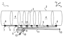
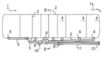
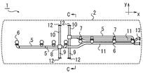
図1〜4に例示するように本発明のタンク装置1は、トラクタヘッドに牽引されるタンクトレーラやトラクタヘッドと一体に構成されたいわゆる単車に搭載され車両とともに移動するものであり、タンク2と、このタンク2に連結された配管とを備えている。このタンク2は、内部を隔離壁3により複数の液体貯蔵室4に分割され、例えばガソリンや軽油、灯油等の異なる種類の液体を複数の液体貯蔵室4にそれぞれ独立して貯蔵することができる。それぞれの液体貯蔵室4の底部には開閉する底弁6が設けられている。
As illustrated in FIGS. 1 to 4, the tank device 1 of the present invention is mounted on a tank trailer to be pulled by a tractor head or a so-called single vehicle integrated with the tractor head, and moves with the vehicle. And a pipe connected to the
タンク2に連結される配管は、タンク2の外側の底部であってタンク2の前後方向(図1x軸方向)に延設した主搬送管5と、この主搬送管5から分岐させて液体貯蔵室4の底弁6にそれぞれ連結する枝管7とを備える。この主搬送管5は切換弁8に連結され、各液体貯蔵室4から荷卸しされる液体は、各枝管7から主搬送管5を通過して切換弁8に送られる。
A pipe connected to the
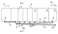
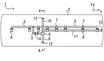
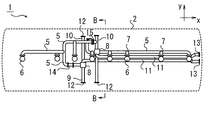
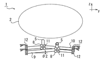
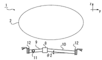
この実施形態では、タンク装置1の配管は、さらに切換弁8からタンク2の外側でタンク2の左右両側(図1y軸方向)に向かって延設する左配管9と右配管10と、切換弁8からタンク2の後方に向かって延設する後方配管11とを備える。左配管9と右配管10とは、一端を切換弁8にそれぞれ連結され他端をタンク2の外側であってタンク2の両側側方にそれぞれ設けられた側方吐出し口12にそれぞれ連結される。図2では左配管9を省略している。
In this embodiment, the piping of the tank apparatus 1 further includes a
後方配管11は、一端を切換弁8に連結され他端をタンク2の後方に設けられた後方吐出し口13に連結される。この後方配管11は、図2に例示するように切換弁8から後方吐出し口13に向かって、水平面に対して下方に傾斜した状態で連結され、この傾斜角度をθ1で示している。また図3に例示するように主搬送管5の途中にポンプ14を設置し
て、灯油等の液体を強制的に荷卸しする構成とすることもできる。
The
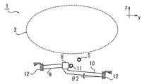
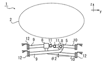
この実施形態では、切換弁8は四方弁であり、主搬送管5と、左配管9または右配管10または後方配管11のいずれか1つの配管とを選択的に連通させる構成になっている。1つの側面に主搬送管5が連結された切換弁8には、別の側面に、図4に例示するように左配管9と後方配管11とがそれぞれ異なる側面に連結され、右配管10が底面に連結される。このとき、左配管9と右配管10は、切換弁8から側方吐出し口12に向かって下方に傾斜した状態で連結され、その傾斜角度をθ2で示している。
In this embodiment, the switching
次に、タンク装置1を搭載したタンクローリ等が、ガソリンスタンドに停止して荷卸しをする際の方法を説明する。まず、作業員によりガソリンスタンドのガソリン貯蔵タンクと例えば左配管9に対応する側方吐出し口12とがホースで連結される。連結後、作業員が左配管9に対応する側方吐出し口12近傍のスイッチを操作すると、切換弁8が動作して主搬送管5と左配管9とだけを連通させる。その後、ガソリンを搭載した液体貯蔵室4の底弁6が作業員により開放される。
Next, a method when the tank truck or the like equipped with the tank device 1 stops at the gas station and unloads will be described. First, a worker connects a gasoline storage tank of a gas station and a
ガソリンは、特別な外力を加えなくても自重によって液体貯蔵室4から枝管7と主搬送管5を通り、切換弁8を通過して左配管9からガソリンスタンドのガソリン貯蔵タンクに荷卸しされる。このとき、右配管10と後方配管11は切換弁8で閉止されているので、右配管10または後方配管11にガソリンが流れ込み、右配管10に対応する側方吐出し口12近傍または後方配管11に対応する後方吐出し口13の近傍にガソリンが溜まり、残液となることはない。そのため、ガソリンの荷役が完了した後に例えば灯油の荷卸しをする際に、配管内にガソリンの残液がないので灯油にガソリンが混ざることを防止できる。また右配管10および後方配管11の残液を処理する従来は必要であった作業が不要となり、作業者の荷卸し作業における負担を大幅に低減することができる。
Gasoline is unloaded from the
左右配管が水平であった従来の場合は、例えばタンクローリの左側が高くなるように傾いているときに左配管から荷卸しすると、左配管は上り傾斜となり、荷卸し完了後に左配管と主搬送管との分岐部分に残液が発生していた。 In the conventional case where the left and right pipes are horizontal, for example, when unloading from the left pipe when the left side of the tank truck is tilted so as to be higher, the left pipe is inclined upward, and after completion of unloading, the left pipe and the main transfer pipe Residual liquid was generated at the branching point.
これに対して、この本発明の左配管9と右配管10は、切換弁8から側方吐出し口12に向かって下方に傾斜しているので、例えばタンクローリの左側が高くなるように傾いている場合であっても、左配管9は下り傾斜となり、荷卸し完了後に左配管9内の切換弁8近傍に残液が発生することを防止できる。
On the other hand, the
図4に例示する左右配管9、10の傾きの角度θ2は、水平面に対して3°以上8°以下とすることが望ましい。ガソリンスタンドの地面の傾きはおおむね2°以内となっているが、たとえ2°の傾きがあったとしても、荷卸しに使用する側の左右配管9、10を下り傾斜に維持できるからである。同様に、後方配管11の傾きの角度θ1も、水平面に対して3°以上8°以下とすることが望ましい。
The inclination angle θ2 of the left and
ガソリンの荷卸しが完了した後に灯油を荷卸しする際には、ガソリンスタンドの灯油貯蔵タンクと左配管9に対応する側方吐出し口12が作業員によりホースで連結される。連結後、灯油を搭載した液体貯蔵室4の底弁6が作業員により開放されると、灯油は対応する枝管7から主搬送管5を通り、切換弁8を通過して左配管9からガソリンスタンドの灯油貯蔵タンクに荷卸しされる。各液体貯蔵室4に積載された液体燃料は、上記の作業を繰り返し順次荷卸しされる。
When unloading kerosene after the unloading of gasoline is completed, the
ガソリンスタンドにおけるガソリン等の貯蔵タンクの配置や、タンクローリ等の車両の停車位置に応じて、左右配管9、10や後方配管11のいずれかが選択され、荷卸しに利
用される。
One of the left and
例えば後方配管11を利用して荷卸しする場合には、作業員が後方吐出し口13近傍のスイッチを操作すると、切換弁8は主搬送管5と後方配管11とだけを連通させる。このように、切換弁8は、例えば後方吐出し口13等の作業者が作業を行っている場所のスイッチにより、対応する配管と主搬送管5とを連通するので、誤って荷役に使用しない配管と主搬送管5が連通して液体が流れ込むことを防止できる。
For example, when unloading using the
また図4に例示するように、この実施形態では切換弁8の側方に後方配管11を連結しているので、後方配管11は切換弁8の底面に連結する場合に比べて、鉛直方向(図4z軸方向)において切換弁8の高い位置に連結することができる。そのため、図2に例示する後方配管11の傾斜角度θ1を大きくすることができるので、後方配管11の途中に液体が溜まり残液となることを防止できる。
Further, as illustrated in FIG. 4, in this embodiment, the
図4に例示する実施形態では右配管10を切換弁8の底面に連結しているが、左配管9を切換弁8の底面に連結する構成とすることもできる。
In the embodiment illustrated in FIG. 4, the
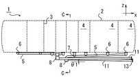
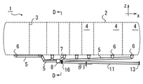
図5〜7に例示するように、例えば液体貯蔵室4を前方の3つと後方の4つの2組にわけて、それぞれに主搬送管5と切換弁8と左右配管9、10と後方配管11とを設置して、配管を2系統とすることもできる。図5では左配管9を省略している。配管を2系統とすると、前方の液体貯蔵室4と後方の液体貯蔵室4からそれぞれ独立した配管で荷卸しできるので、異種の液体であっても同時に荷卸しできる。そのため、荷卸しにかかる時間を短縮して、作業者の荷卸し作業の負担をさらに軽減することができる。
As illustrated in FIGS. 5 to 7, for example, the
この実施形態において配管にポンプ14を設置する場合には、例えば後方側の右配管10と前方側の主搬送管5とを、開閉弁15を介して連結することが望ましい。この開閉弁15を開放すると後方側の液体貯蔵室4の液体は、枝管7と後方側の主搬送管5と後方側の右配管10から開閉弁15を経由して、前方側の主搬送管5を通りポンプ14に移動することができる。そのため、前方側と後方側の両方の液体貯蔵室4に搭載された液体を1台のポンプ14で強制的に荷卸しできる。
In this embodiment, when the
また図6と図7に例示するように、前方側の切換弁8は前方側の側面に主搬送管5を連結され底面に右配管10を連結され、後方側の切換弁8は後方側の側面に主搬送管5を連結され底面に左配管9を連結される。これにより、タンク2の下方の空間が狭い場合であっても、配管を効率的に配置することができる。
Further, as illustrated in FIGS. 6 and 7, the front
図8〜10に例示するように、切換弁8の天面に主搬送管5を連結する構成とすることもできる。この実施形態は、2系統の配管を備えてポンプを設置しない構成である。この実施形態の切換弁8は、左配管9と右配管10と後方配管11を側面に連結される。切換弁8の上から液体が流れ込むことにより、切換弁8を通過する液体の流速が相対的に大きくなるので、左右配管9、10や後方配管11の途中で液体の流速が減少し停滞して残液となる可能性を抑制できる。また左配管9と右配管10の両方を切換弁8の側面に連結できるので、左右配管9、10の傾斜角度θ2を大きくするには有利である。
As illustrated in FIGS. 8 to 10, the
この実施形態のタンク装置1は、切換弁8の上方に主搬送管5を連結するための空間が必要となるので、タンク2の下方の空間が広いタンクトレーラに採用することが望ましい。またこの実施形態のタンク装置1において、配管を1系統としてもよい。また図5〜7の実施形態と同様にポンプ14および開閉弁15を設置する構成とすることもできる。
Since the tank apparatus 1 of this embodiment requires a space for connecting the
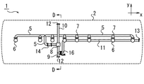
図11〜13に例示するように切換弁8を三方弁で構成し、主搬送管5と左配管9と右
配管10とを切換弁8の側方に連結する構成とすることもできる。この実施形態は1系統の配管を備えてポンプ14を設置する構成である。この実施形態では、この三方弁は主搬送管5と、左配管9または右配管10のいずれか1つを選択的に連通する。三方弁は四方弁に比べて簡易な構成であり、安価に製造できるので、タンク装置1の製造コストを抑制するには有利である。また三方弁は四方弁に比べ小さく作成することができるので、タンク2の下方に十分な空間がない場合であっても利用することができる。
As illustrated in FIGS. 11 to 13, the switching
この実施形態では、例えば左配管9に後方開閉弁16を介して後方配管11を連結する。後方配管11に対応する後方吐出し口13から荷卸しをする場合には、切換弁8で主搬送管5と左配管9を連通させる。液体は左配管9と開放された後方開閉弁16を経由して後方配管11に移動する。
In this embodiment, for example, the
このとき微量ではあるが、左配管9の側方吐出し口12の近傍に残液が生じる可能性はある。しかし、後方配管11を利用した荷卸しが行われる頻度は低いので、この実施形態のタンク装置1であっても、作業者が残液処理を行う頻度は従来に比べて格段に低く、作業者の負担を十分に低減することができる。
At this time, there is a possibility that a residual liquid is generated in the vicinity of the
本発明のタンク装置1は、液体燃料を運搬する物に限らず、その他の化学物質等の液体を運搬する際にも利用することができる。 The tank apparatus 1 according to the present invention is not limited to an object that transports liquid fuel, but can also be used when transporting liquids such as other chemical substances.
1 タンク装置
2 タンク
3 隔離壁
4 液体貯蔵室
5 主搬送管
6 底弁
7 枝管
8 切換弁
9 左配管
10 右配管
11 後方配管
12 側方吐出し口
13 後方吐出し口
DESCRIPTION OF SYMBOLS 1
Claims (4)
前記左配管および右配管は、それぞれの一端が前記主搬送管との分岐部分に設置された切換弁に連結され、それぞれの他端が前記側方吐出し口のうちの同じ側に設けられた側方吐出し口に連結され、前記切換弁から前記側方吐出し口に向かって下方に傾斜した状態で延設され、
前記切換弁は、前記主搬送管とこの切換弁に連結された他のいずれか1つの配管とを選択的に連通させる構成を備えたことを特徴とするタンク装置。 A tank divided into a plurality of liquid storage chambers by an isolation wall inside, a main transfer pipe arranged on the tank bottom outside the tank and extending in the tank front-rear direction, and branched from the main transfer pipe, A plurality of branch pipes connected to the bottom valve of the liquid storage chamber, and a left pipe connected to each side discharge port branched from the main transfer pipe and disposed on both the left and right sides of the tank outside the tank And a tank device that moves with the vehicle, including a right pipe,
The left pipe and the right pipe are each connected at one end to a switching valve installed at a branch portion with the main transport pipe, and each other end is provided on the same side of the side discharge port. It is connected to a side discharge port, and extends in a state inclined downward from the switching valve toward the side discharge port,
The said switching valve is provided with the structure which selectively connected the said main conveyance pipe | tube and any other piping connected with this switching valve, The tank apparatus characterized by the above-mentioned.
Priority Applications (1)
| Application Number | Priority Date | Filing Date | Title |
|---|---|---|---|
| JP2014038887A JP6182477B2 (en) | 2014-02-28 | 2014-02-28 | Tank equipment |
Applications Claiming Priority (1)
| Application Number | Priority Date | Filing Date | Title |
|---|---|---|---|
| JP2014038887A JP6182477B2 (en) | 2014-02-28 | 2014-02-28 | Tank equipment |
Publications (2)
| Publication Number | Publication Date |
|---|---|
| JP2015160661A true JP2015160661A (en) | 2015-09-07 |
| JP6182477B2 JP6182477B2 (en) | 2017-08-16 |
Family
ID=54184028
Family Applications (1)
| Application Number | Title | Priority Date | Filing Date |
|---|---|---|---|
| JP2014038887A Active JP6182477B2 (en) | 2014-02-28 | 2014-02-28 | Tank equipment |
Country Status (1)
| Country | Link |
|---|---|
| JP (1) | JP6182477B2 (en) |
Cited By (1)
| Publication number | Priority date | Publication date | Assignee | Title |
|---|---|---|---|---|
| CN113945199A (en) * | 2021-09-30 | 2022-01-18 | 广东石油化工学院 | A method and system for hydraulic detection of dangerous goods transport vehicles based on attitude detection |
Citations (9)
| Publication number | Priority date | Publication date | Assignee | Title |
|---|---|---|---|---|
| JPS6212553U (en) * | 1985-07-09 | 1987-01-26 | ||
| JPH054675A (en) * | 1991-06-28 | 1993-01-14 | Tatsuno Co Ltd | Tank lorry |
| JPH06127600A (en) * | 1992-10-21 | 1994-05-10 | Tatsuno Co Ltd | Piping device for bottom truck |
| JPH11105978A (en) * | 1997-10-03 | 1999-04-20 | Tokyu Car Corp | Tank car |
| JP2006027681A (en) * | 2004-07-16 | 2006-02-02 | Tokyu Car Corp | Piping structure for tanker |
| JP2006062749A (en) * | 2004-07-26 | 2006-03-09 | Tokyu Car Corp | Piping structure for tank truck |
| US20070006927A1 (en) * | 2005-07-05 | 2007-01-11 | Oshkosh Truck Corporation | Apparatus for discharging fluid |
| JP2007239797A (en) * | 2006-03-06 | 2007-09-20 | Showa Aircraft Ind Co Ltd | Tank lorry four-way valve |
| JP2010126194A (en) * | 2008-11-27 | 2010-06-10 | Tokiko Techno Kk | Unloading system of tank lorry |
-
2014
- 2014-02-28 JP JP2014038887A patent/JP6182477B2/en active Active
Patent Citations (9)
| Publication number | Priority date | Publication date | Assignee | Title |
|---|---|---|---|---|
| JPS6212553U (en) * | 1985-07-09 | 1987-01-26 | ||
| JPH054675A (en) * | 1991-06-28 | 1993-01-14 | Tatsuno Co Ltd | Tank lorry |
| JPH06127600A (en) * | 1992-10-21 | 1994-05-10 | Tatsuno Co Ltd | Piping device for bottom truck |
| JPH11105978A (en) * | 1997-10-03 | 1999-04-20 | Tokyu Car Corp | Tank car |
| JP2006027681A (en) * | 2004-07-16 | 2006-02-02 | Tokyu Car Corp | Piping structure for tanker |
| JP2006062749A (en) * | 2004-07-26 | 2006-03-09 | Tokyu Car Corp | Piping structure for tank truck |
| US20070006927A1 (en) * | 2005-07-05 | 2007-01-11 | Oshkosh Truck Corporation | Apparatus for discharging fluid |
| JP2007239797A (en) * | 2006-03-06 | 2007-09-20 | Showa Aircraft Ind Co Ltd | Tank lorry four-way valve |
| JP2010126194A (en) * | 2008-11-27 | 2010-06-10 | Tokiko Techno Kk | Unloading system of tank lorry |
Cited By (2)
| Publication number | Priority date | Publication date | Assignee | Title |
|---|---|---|---|---|
| CN113945199A (en) * | 2021-09-30 | 2022-01-18 | 广东石油化工学院 | A method and system for hydraulic detection of dangerous goods transport vehicles based on attitude detection |
| CN113945199B (en) * | 2021-09-30 | 2023-08-22 | 广东石油化工学院 | A hydraulic detection method and system for dangerous goods transport vehicles based on attitude detection |
Also Published As
| Publication number | Publication date |
|---|---|
| JP6182477B2 (en) | 2017-08-16 |
Similar Documents
| Publication | Publication Date | Title |
|---|---|---|
| US10926996B2 (en) | Mobile distribution station having adjustable feed network | |
| US8882336B1 (en) | Hydro-blender | |
| US10753497B2 (en) | Shutoff-opening device | |
| JP6182477B2 (en) | Tank equipment | |
| US10717639B2 (en) | Mobile auxiliary distribution station | |
| JP2005088930A (en) | Liquid mixture preventive device of liquid transporting vehicle | |
| US12311823B2 (en) | Tank trailer with fluid collection system | |
| CN210795094U (en) | Portable liquid bulk cargo ration device of unloading ship | |
| US20200102201A1 (en) | Fluid Delivery Device | |
| CA3051985A1 (en) | Mobile distribution station having satellite dish | |
| CN204005245U (en) | The many material-transporting systems of a kind of harbour A-grade in the first class's class | |
| US10030676B2 (en) | Hydraulic fluid supply apparatus and methods | |
| KR101262647B1 (en) | Natural gas hydrate loading device | |
| US11795050B2 (en) | Device and method for pumping low evaporation products under vacuum | |
| US20130113203A1 (en) | Kit of parts for assembling a hose connection, a fuel dispensing unit having such a hose connection, and a method for assembling such a hose connection | |
| CN111745414B (en) | Automatic assembly line and its control method | |
| CN109515295A (en) | Tank truck | |
| CN205087908U (en) | Filling device and tank service truck | |
| KR102768902B1 (en) | Automatic chemical supply system having transfer stage | |
| KR20140032611A (en) | Pipe coupling assembly for liquid cargo | |
| CN104373810A (en) | Loading and unloading device for low-temperature railway transportation tanker | |
| CN222271907U (en) | Tank box communication pipeline and liquid transportation tank truck with same | |
| JPS6154679B2 (en) | ||
| CN203568835U (en) | Pipe matching exchanging station used for goods inlet and outlet system in oil depot tank field | |
| CN104879650A (en) | Slurry conveying system |
Legal Events
| Date | Code | Title | Description |
|---|---|---|---|
| A621 | Written request for application examination |
Free format text: JAPANESE INTERMEDIATE CODE: A621 Effective date: 20160520 |
|
| A977 | Report on retrieval |
Free format text: JAPANESE INTERMEDIATE CODE: A971007 Effective date: 20170306 |
|
| A131 | Notification of reasons for refusal |
Free format text: JAPANESE INTERMEDIATE CODE: A131 Effective date: 20170314 |
|
| A521 | Request for written amendment filed |
Free format text: JAPANESE INTERMEDIATE CODE: A523 Effective date: 20170427 |
|
| TRDD | Decision of grant or rejection written | ||
| A01 | Written decision to grant a patent or to grant a registration (utility model) |
Free format text: JAPANESE INTERMEDIATE CODE: A01 Effective date: 20170711 |
|
| A61 | First payment of annual fees (during grant procedure) |
Free format text: JAPANESE INTERMEDIATE CODE: A61 Effective date: 20170724 |
|
| R150 | Certificate of patent or registration of utility model |
Ref document number: 6182477 Country of ref document: JP Free format text: JAPANESE INTERMEDIATE CODE: R150 |
|
| R250 | Receipt of annual fees |
Free format text: JAPANESE INTERMEDIATE CODE: R250 |
|
| R250 | Receipt of annual fees |
Free format text: JAPANESE INTERMEDIATE CODE: R250 |
|
| R250 | Receipt of annual fees |
Free format text: JAPANESE INTERMEDIATE CODE: R250 |
|
| R250 | Receipt of annual fees |
Free format text: JAPANESE INTERMEDIATE CODE: R250 |
|
| R250 | Receipt of annual fees |
Free format text: JAPANESE INTERMEDIATE CODE: R250 |
|
| S531 | Written request for registration of change of domicile |
Free format text: JAPANESE INTERMEDIATE CODE: R313532 |
|
| R350 | Written notification of registration of transfer |
Free format text: JAPANESE INTERMEDIATE CODE: R350 |
|
| R250 | Receipt of annual fees |
Free format text: JAPANESE INTERMEDIATE CODE: R250 |