JP2015160271A - Control device, robot, robot system and control method - Google Patents
Control device, robot, robot system and control method Download PDFInfo
- Publication number
- JP2015160271A JP2015160271A JP2014036401A JP2014036401A JP2015160271A JP 2015160271 A JP2015160271 A JP 2015160271A JP 2014036401 A JP2014036401 A JP 2014036401A JP 2014036401 A JP2014036401 A JP 2014036401A JP 2015160271 A JP2015160271 A JP 2015160271A
- Authority
- JP
- Japan
- Prior art keywords
- robot
- end effector
- assembly
- robot arm
- workpiece
- Prior art date
- Legal status (The legal status is an assumption and is not a legal conclusion. Google has not performed a legal analysis and makes no representation as to the accuracy of the status listed.)
- Pending
Links
- 238000000034 method Methods 0.000 title claims abstract description 45
- 239000012636 effector Substances 0.000 claims abstract description 87
- 238000003384 imaging method Methods 0.000 claims abstract description 63
- 238000001514 detection method Methods 0.000 claims abstract description 25
- 230000008859 change Effects 0.000 claims description 8
- 238000000605 extraction Methods 0.000 claims description 4
- 239000003550 marker Substances 0.000 description 28
- 230000008569 process Effects 0.000 description 27
- 238000010586 diagram Methods 0.000 description 9
- 238000012545 processing Methods 0.000 description 9
- 230000006870 function Effects 0.000 description 7
- 230000002950 deficient Effects 0.000 description 5
- 230000006872 improvement Effects 0.000 description 5
- 238000003780 insertion Methods 0.000 description 5
- 230000037431 insertion Effects 0.000 description 5
- 239000000284 extract Substances 0.000 description 4
- 239000007787 solid Substances 0.000 description 4
- 238000013459 approach Methods 0.000 description 3
- 239000003086 colorant Substances 0.000 description 2
- 230000000694 effects Effects 0.000 description 2
- 238000013461 design Methods 0.000 description 1
- 238000002474 experimental method Methods 0.000 description 1
- 230000004044 response Effects 0.000 description 1
- 238000004088 simulation Methods 0.000 description 1
Images


Landscapes
- Manipulator (AREA)
Abstract
【課題】第1の物体と第2の物体との組立の良否を迅速に把握することができる制御装置、ロボット、ロボットシステムおよび制御方法を提供すること。
【解決手段】制御装置は、エンドエフェクターが装着されるロボットアームと、力検出部とを備えた、第1ワークと第2ワークとを組み立てる組立を行なうロボットを制御する。制御装置は、ロボットアームの作動を制御する制御部と、第1ワークを支持したエンドエフェクターを含む領域を撮像して、撮像データーを得る撮像部と、組立の良否判定を行なう良否判定部とを備える。制御部は、撮像データーに基づいて、第1ワークと第2ワークとの位置合わせを行なうようにロボットアームを作動させて、組立を開始し、力検出部の検出結果に基づいて、組立が現に行なわれるようにロボットアームを作動させる。良否判定部は、組立が行なわれている最中に、撮像データーに基づいて、良否判定を行なう。
【選択図】図12To provide a control device, a robot, a robot system, and a control method capable of quickly grasping whether or not a first object and a second object are assembled.
A control device controls a robot having a robot arm on which an end effector is mounted and a force detection unit for assembling a first workpiece and a second workpiece. The control device includes a control unit that controls the operation of the robot arm, an imaging unit that captures an area including the end effector that supports the first workpiece and obtains imaging data, and a pass / fail determination unit that performs assembly pass / fail determination. Prepare. Based on the imaging data, the control unit starts the assembly by operating the robot arm so as to align the first work and the second work, and the assembly is actually performed based on the detection result of the force detection unit. Actuate the robot arm as done. The pass / fail determination unit performs pass / fail determination based on the imaging data during assembly.
[Selection] Figure 12
Description
本発明は、制御装置、ロボット、ロボットシステムおよび制御方法に関する。 The present invention relates to a control device, a robot, a robot system, and a control method.
従来、先端部にロボットハンドを装着することができる多関節ロボットアームが知られている(例えば、特許文献1参照)。この多関節ロボットアームは、例えば、2つのワーク同士を組み立てる組立作業を行なうことができる。組立作業を行なう際には、ロボットハンドで2つのワークのうちの一方のワークを把持して、作業台上に固定された他方のワークに力制御を行いながら挿入し、2つのワークの組立体である完成品を得る。 Conventionally, an articulated robot arm in which a robot hand can be attached to the tip is known (see, for example, Patent Document 1). This articulated robot arm can perform, for example, an assembling operation to assemble two workpieces. When assembling, the robot hand grasps one of the two workpieces and inserts it into the other workpiece fixed on the workbench while performing force control. Get the finished product.
力制御は、部品同士のばらつきによる微妙な位置ずれに対応して組み立てできる柔軟な制御である反面、部品の位置ずれが許容範囲を超えていた場合、ロボットがなんらかの判断をしない限り、永久に部品の挿入を試みるか、完了したつもりで作業を終了する。特許文献1に記載の多関節ロボットアームを備えるロボットシステムでは、組立作業後に、この組立が成功したのか、または、失敗したのかを判別していた、すなわち、組立の良否の判別をしていた。
Force control is a flexible control that can be assembled in response to subtle misalignment due to component-to-component variations.On the other hand, if the misalignment of a component exceeds the allowable range, the component is permanently used unless the robot makes a judgment. Try to insert or finish the work as if it were completed. In the robot system including the articulated robot arm described in
しかしながら、このようなロボットシステムでは、例えば、一方のワークが組立作業中に落下したり、適正な姿勢からズレたりした場合であっても、組立作業を継続してしまう。その結果、得られた完成品は、例えば一方のワークが欠落した不良品となっている。そして、この不良品は、組立作業が完了して初めて把握される(認識される)こととなり、歩留まりが悪いという問題があった。 However, in such a robot system, for example, even if one workpiece falls during assembly work or is displaced from an appropriate posture, the assembly work is continued. As a result, the obtained finished product is, for example, a defective product in which one workpiece is missing. This defective product is grasped (recognized) only after the assembly work is completed, and there is a problem that the yield is poor.
本発明の目的は、第1の物体と第2の物体との組立の良否を迅速に把握することができる制御装置、ロボット、ロボットシステムおよび制御方法を提供することにある。 An object of the present invention is to provide a control device, a robot, a robot system, and a control method that can quickly grasp the quality of assembly of a first object and a second object.
このような目的は、下記の本発明に係る適用例により達成される。
(適用例1)
本発明に係る制御装置は、エンドエフェクターとロボットアームと、前記ロボットアームと前記エンドエフェクターとの間に設けられる力検出部と、を備え、第1の物体と第2の物体とを組み立てるロボットを制御する制御装置であって、
前記ロボットアームの動きを制御する制御部と、
撮像データーを得る撮像部と、
を備え、
前記制御部は、組立開始前にエンドエフェクターを少なくとも含む領域を前記撮像部で撮像して前記ロボットアームを動作させ、組立開始後に、少なくとも前記力検出部から出力値が出力されている間前記ロボットアームを動作させ、さらに前記第1の物体と前記第2の物体の組立部を撮像することを特徴とする。
Such an object is achieved by the following application example according to the present invention.
(Application example 1)
A control device according to the present invention includes an end effector, a robot arm, and a force detection unit provided between the robot arm and the end effector, and a robot that assembles a first object and a second object. A control device for controlling,
A control unit for controlling the movement of the robot arm;
An imaging unit for obtaining imaging data;
With
The controller picks up an area including at least an end effector with the image pickup unit before starting assembly and operates the robot arm, and after the start of assembly, at least while the output value is output from the force detector The arm is operated, and an image of the assembly part of the first object and the second object is captured.
これにより、第1の物体と第2の物体との組立が完了するよりも以前に、すなわち、第1の物体と第2の物体との組立が行なわれている最中に、当該組立の良否を迅速に把握することができる。そして、良否判定が良であれば、第1の物体と第2の物体との組立体をそのまま次の工程に移行することができ、良否判定が否であれば、組立を再度行なって、組立体を得ることができ、よって、歩留まりの向上にも寄与する。 As a result, whether the assembly is good or bad before the assembly of the first object and the second object is completed, that is, during the assembly of the first object and the second object. Can be grasped quickly. If the pass / fail judgment is good, the assembly of the first object and the second object can be transferred to the next process as it is. If the pass / fail judgment is negative, the assembly is performed again, and the assembly is performed. A solid body can be obtained, which contributes to an improvement in yield.
(適用例2)
本発明に係る制御装置では、前記組立の良否判定を行なう良否判定部を備え、
前記良否判定部は前記撮像データーに基づいて前記良否判定を行ない、
前記良否判定が良の場合には、前記組立が完了するまで前記組立を継続するのが好ましい。
これにより、第1の物体と第2の物体との組立をその完了まで迅速に行なうことができる。
(Application example 2)
In the control device according to the present invention, the control device includes a quality determination unit that performs quality determination of the assembly,
The quality determination unit performs the quality determination based on the imaging data,
When the quality determination is good, it is preferable to continue the assembly until the assembly is completed.
As a result, the assembly of the first object and the second object can be performed quickly until completion.
(適用例3)
本発明に係る制御装置では、前記良否判定の結果が否の場合には、前記組立を一旦中断し、前記エンドエフェクターで前記第1の物体および前記第2の物体の少なくとも一方を支持し直し、前記組立を再開する制御を行なうのが好ましい。
これにより、第1の物体と第2の物体との組立が一旦不成功になったとしても、当該組立を成功に導くことができる。
(Application example 3)
In the control device according to the present invention, if the result of the quality determination is NO, the assembly is temporarily stopped, and at least one of the first object and the second object is supported by the end effector, It is preferable to perform control to resume the assembly.
Thereby, even if the assembly of the first object and the second object is once unsuccessful, the assembly can be led to success.
(適用例4)
本発明に係る制御装置では、前記良否判定部は、前記第1の物体および前記第2の物体の少なくとも一方の前記エンドエフェクターに対する姿勢の変化量が閾値を超えた場合に前記良否判定を否とするのが好ましい。
これにより、良否判定を簡単かつ迅速に行なうことができる。
(Application example 4)
In the control device according to the present invention, the pass / fail judgment unit rejects the pass / fail judgment when an amount of change in posture of at least one of the first object and the second object with respect to the end effector exceeds a threshold value. It is preferable to do this.
Thereby, the pass / fail determination can be performed easily and quickly.
(適用例5)
本発明に係る制御装置では、前記第1の物体および前記第2の物体の少なくとも一方と前記エンドエフェクターの各特徴点を抽出する抽出部を備え、
前記変化量は、前記第1の物体および前記第2の物体の少なくとも一方の特徴点と、前記エンドエフェクターの特徴点との位置関係の変化であるのが好ましい。
これにより、良否判定をより簡単かつより迅速に行なうことができる。
(Application example 5)
The control device according to the present invention includes an extraction unit that extracts at least one of the first object and the second object and each feature point of the end effector,
The amount of change is preferably a change in a positional relationship between a feature point of at least one of the first object and the second object and a feature point of the end effector.
Thereby, the pass / fail determination can be performed more easily and more quickly.
(適用例6)
本発明に係る制御装置では、前記撮像データーには、前記第1の物体と前記第2の物体との位置合わせを行なうときに用いられる第1撮像データーと、前記第1撮像データーと異なるタイミングで得られ、前記良否判定を行なうときに用いられる第2撮像データーとが含まれるのが好ましい。
これにより、第1の物体と第2の物体との位置合わせを行なう処理と、良否判定を行なう処理との各種処理条件に適した撮像データーを用いることができる。
(Application example 6)
In the control device according to the present invention, the imaging data includes the first imaging data used when aligning the first object and the second object, and at a timing different from the first imaging data. It is preferable that the second imaging data obtained and used when the quality determination is performed are included.
As a result, it is possible to use imaging data suitable for various processing conditions such as processing for positioning the first object and the second object and processing for determining pass / fail.
(適用例7)
本発明に係る制御装置では、前記撮像部は、1つのカメラで構成され、
前記カメラで前記第1撮像データーと前記第2撮像データーとを得るのが好ましい。
これにより、1つのカメラを兼用することができ、よって、カメラの設置数を抑制することができる。
(Application example 7)
In the control device according to the present invention, the imaging unit is composed of one camera,
It is preferable that the first imaging data and the second imaging data are obtained by the camera.
Thereby, one camera can be used also, and therefore the number of installed cameras can be suppressed.
(適用例8)
本発明に係る制御装置では、前記制御部は、前記ロボットアームに対してインピーダンス制御を行なうよう構成されているのが好ましい。
これにより、組立が行なわれている最中に一方の物体が他方の物体とぶつかったときにも、当該他方の物体とやわらかく接することができ、よって、各物体の損傷を防止することができる。
(Application example 8)
In the control device according to the present invention, it is preferable that the control unit is configured to perform impedance control on the robot arm.
As a result, even when one object collides with the other object during assembly, the other object can be softly contacted with each other, and damage to each object can be prevented.
(適用例9)
本発明に係るロボットは、第1の物体および第2の物体の少なくとも一方を支持するエンドエフェクターが装着されるロボットアームを含むロボットであって、
前記ロボットアームと前記エンドエフェクターとの間に設けられて情報を検出する力検出部と、
前記エンドエフェクターを含む領域を撮像して、撮像データーを得る撮像部と、
前記撮像データーに基づいて前記ロボットアームを動作させて前記第1の物体と前記第2の物体との位置合わせを行ない、前記力検出部の検出結果に基づいて、前記ロボットアームを動作させて前記第1の物体と前記第2の物体との組立を行なう制御部と、
前記撮像データーに基づいて前記組立の良否判定を行なう良否判定部と、を備えることを特徴とする。
(Application example 9)
A robot according to the present invention is a robot including a robot arm to which an end effector that supports at least one of a first object and a second object is attached,
A force detector provided between the robot arm and the end effector for detecting information;
An imaging unit that captures imaging data by imaging an area including the end effector;
The robot arm is operated based on the imaging data to align the first object and the second object, and the robot arm is operated based on the detection result of the force detection unit. A control unit for assembling the first object and the second object;
A quality determination unit that determines quality of the assembly based on the imaging data.
これにより、第1の物体と第2の物体との組立が完了するよりも以前に、すなわち、第1の物体と第2の物体との組立が行なわれている最中に、当該組立の良否を迅速に把握することができる。そして、良否判定が良であれば、第1の物体と第2の物体との組立体をそのまま次の工程に移行することができ、良否判定が否であれば、組立を再度行なって、組立体を得ることができ、よって、歩留まりの向上にも寄与する。 As a result, whether the assembly is good or bad before the assembly of the first object and the second object is completed, that is, during the assembly of the first object and the second object. Can be grasped quickly. If the pass / fail judgment is good, the assembly of the first object and the second object can be transferred to the next process as it is. If the pass / fail judgment is negative, the assembly is performed again, and the assembly is performed. A solid body can be obtained, which contributes to an improvement in yield.
(適用例10)
本発明に係るロボットでは、前記ロボットアームを2本備え、
一方の前記ロボットアームに装着された前記エンドエフェクターで前記第1の物体を支持し、他方の前記ロボットアームに装着された前記エンドエフェクターで前記第2の物体を支持するのが好ましい。
これにより、第1の物体と第2の物体との組立を迅速に行なうことができる。
(Application Example 10)
The robot according to the present invention comprises two robot arms,
It is preferable that the first object is supported by the end effector attached to one of the robot arms, and the second object is supported by the end effector attached to the other robot arm.
Thereby, the assembly of the first object and the second object can be performed quickly.
(適用例11)
本発明に係るロボットでは、前記力検出部は、力覚センサーで構成されているのが好ましい。
これにより、簡単な構成で、ロボットアームが受ける力を検出することができる。
(Application Example 11)
In the robot according to the present invention, it is preferable that the force detection unit is constituted by a force sensor.
Thereby, the force received by the robot arm can be detected with a simple configuration.
(適用例12)
本発明に係るロボットシステムは、第1の物体および第2の物体の少なくとも一方を支持するエンドエフェクターが装着される少なくとも1本のロボットアームと、
前記ロボットアームと前記エンドエフェクターとの間に設けられて前記エンドエフェクターが受ける力情報を検出する力検出部と、を備えて、
前記第1の物体と前記第2の物体を組み立てるロボットを制御する、上記制御装置と、を備えることを特徴とする。
これにより、第1の物体と第2の物体との組立が完了するよりも以前に、すなわち、第1の物体と第2の物体との組立が行なわれている最中に、当該組立の良否を迅速に把握することができる。そして、良否判定が良であれば、第1の物体と第2の物体との組立体をそのまま次の工程に移行することができ、良否判定が否であれば、組立を再度行なって、組立体を得ることができ、よって、歩留まりの向上にも寄与する。
(Application Example 12)
A robot system according to the present invention includes at least one robot arm to which an end effector that supports at least one of a first object and a second object is attached;
A force detection unit that is provided between the robot arm and the end effector and detects force information received by the end effector;
And a controller for controlling a robot that assembles the first object and the second object.
As a result, whether the assembly is good or bad before the assembly of the first object and the second object is completed, that is, during the assembly of the first object and the second object. Can be grasped quickly. If the pass / fail judgment is good, the assembly of the first object and the second object can be transferred to the next process as it is. If the pass / fail judgment is negative, the assembly is performed again, and the assembly is performed. A solid body can be obtained, which contributes to an improvement in yield.
(適用例13)
本発明に係るロボットシステムでは、前記ロボットアームを2本備え、
一方の前記ロボットアームに装着された前記エンドエフェクターで前記第1の物体を支持し、他方の前記ロボットアームに装着された前記エンドエフェクターで前記第2の物体を支持するのが好ましい。
これにより、第1の物体と第2の物体との組立を迅速に行なうことができる。
(Application Example 13)
The robot system according to the present invention comprises two robot arms,
It is preferable that the first object is supported by the end effector attached to one of the robot arms, and the second object is supported by the end effector attached to the other robot arm.
Thereby, the assembly of the first object and the second object can be performed quickly.
(適用例14)
本発明に係るロボットシステムでは、前記力検出部は、力覚センサーで構成されているのが好ましい。
これにより、簡単な構成で、ロボットアームが受ける力を検出することができる。
(Application Example 14)
In the robot system according to the present invention, it is preferable that the force detection unit includes a force sensor.
Thereby, the force received by the robot arm can be detected with a simple configuration.
(適用例15)
本発明に係る制御方法は、第1の物体および第2の物体の少なくとも一方を支持するエンドエフェクターが装着されるロボットアームを含むロボットを制御する制御方法であって、
前記第1の物体および前記第2の物体の少なくとも一方を支持した前記エンドエフェクターを含む領域を撮像した撮像データーに基づいて前記ロボットアームを動作させて前記第1の物体と前記第2の物体との位置合わせを行ない、前記ロボットアームと前記エンドエフェクターとの間に設けられた力検出部が検出する検出結果に基づいて、前記ロボットアームを動作させて前記第1の物体と前記第2の物体との組立を行なうとともに、前記撮像データーに基づいて、前記組立の良否判定を行なうことを特徴とする。
これにより、第1の物体と第2の物体との組立が完了するよりも以前に、すなわち、第1の物体と第2の物体との組立が行なわれている最中に、当該組立の良否を迅速に把握することができる。そして、良否判定が良であれば、第1の物体と第2の物体との組立体をそのまま次の工程に移行することができ、良否判定が否であれば、組立を再度行なって、組立体を得ることができ、よって、歩留まりの向上にも寄与する。
(Application Example 15)
A control method according to the present invention is a control method for controlling a robot including a robot arm to which an end effector supporting at least one of a first object and a second object is attached,
The robot arm is operated based on imaging data obtained by imaging an area including the end effector that supports at least one of the first object and the second object, and the first object and the second object The first object and the second object are operated by operating the robot arm based on a detection result detected by a force detection unit provided between the robot arm and the end effector. And the quality of the assembly is determined based on the imaging data.
As a result, whether the assembly is good or bad before the assembly of the first object and the second object is completed, that is, during the assembly of the first object and the second object. Can be grasped quickly. If the pass / fail judgment is good, the assembly of the first object and the second object can be transferred to the next process as it is. If the pass / fail judgment is negative, the assembly is performed again, and the assembly is performed. A solid body can be obtained, which contributes to an improvement in yield.
以下、本発明に係る制御装置、ロボット、ロボットシステムおよび制御方法を添付図面に示す好適な実施形態に基づいて詳細に説明する。
<第1実施形態>
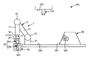
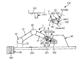
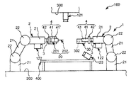
図1〜図8は、それぞれ、本発明に係るロボットシステム(制御装置)(第1実施形態)による第1ワークと第2ワークとの組み立て過程を順に示す側面図、図9は、図1〜図8に示すロボットシステムのブロック図、図10および図11は、それぞれ、エンドエフェクターによる第1ワークの把持状態を示す図、図12は、本発明に係るロボットシステム(制御装置)の制御プログラムを示すフローチャートである。なお、以下では、説明の都合上、図1〜図8中(図13、図15、図17についても同様)の上側を「上」または「上方」、下側を「下」または「下方」と言い、エンドエフェクター側を「先端」、その反対側を「基端」と言う。
Hereinafter, a control device, a robot, a robot system, and a control method according to the present invention will be described in detail based on preferred embodiments shown in the accompanying drawings.
<First Embodiment>
1 to 8 are side views showing the assembly process of the first workpiece and the second workpiece in order by the robot system (control device) (first embodiment) according to the present invention, respectively, and FIG. FIG. 8 is a block diagram of the robot system shown in FIG. 8, FIG. 10 and FIG. 11 are diagrams showing the gripping state of the first workpiece by the end effector, and FIG. It is a flowchart to show. In the following, for convenience of explanation, the upper side in FIGS. 1 to 8 (the same applies to FIGS. 13, 15 and 17) is “upper” or “upper”, and the lower side is “lower” or “lower”. The end effector side is called the “tip”, and the opposite side is called the “base end”.
図1〜図9に示すように、ロボットシステム100は、ロボット1と制御装置10とを備え、第1ワーク(第1の物体)20と第2ワーク(第2の物体)30との組立体(組立部)40を得るのに用いられる。
まず、ロボットシステム100の各部の構成について説明する前に、第1ワーク20、第2ワーク30の構成ついて説明する。
As shown in FIGS. 1 to 9, the
First, before describing the configuration of each part of the
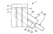
図1〜図8に示すように、第1ワーク20は、基部201と、基部201から突出形成された突出部202とで構成されている。
図10、図11に示すように、基部201は、正四角柱状をなす部分である。基部201の4つの側面203には、それぞれ、マーカー204が付されている。各マーカー204は、それぞれ、側面203の長手方向に沿って延在しており、側面203の幅方向の中央部に配置されている。なお、マーカー204は、例えば、印刷されたものであってもよいし、シール等のように貼り付けされたものであってもよい。
As shown in FIGS. 1-8, the 1st workpiece |
As shown in FIGS. 10 and 11, the
突出部202は、基部201の一端面205から突出し、基部201よりも細い部分である。突出部202の横断面形状は、円形をなしている。なお、突出部202は、基部201と一体的に形成されたものであってもよいし、別体で構成されたものであってもよい。
また、第1ワーク20は、組み立てられる前は、載置ボックス50に載置されている。載置ボックス50は、第1ワーク20の突出部202が挿入される凹部501を有し、これにより、第1ワーク20を起立した状態で支持することができる。このとき、基部201は、上方に露出する。
The protruding
The
図1(図2〜図8も同様)に示すように、第2ワーク30は、四角錐台形状をなす部材で構成されている。この第2ワーク30の傾斜した4つの側面301のうちの1つには、凹部302が開口している。凹部302は、その中心軸が側面301と直交するように形成されている。図5に示すように、凹部302には、第1ワーク20の突出部202が挿入される。そして、この挿入により、組立体40が製造される。
As shown in FIG. 1 (the same applies to FIGS. 2 to 8), the
また、第2ワーク30は、床面200に載置されており、組立に先立って準備されている。
次に、ロボットシステム100の各部の構成について説明する。
前述したように、ロボットシステム100は、ロボット1と、制御装置10とを備えている。
Moreover, the 2nd workpiece |
Next, the configuration of each part of the
As described above, the
ロボット1は、第1ワーク20と第2ワーク30とを組み立てる組立を行なう装置である。このロボット1は、ロボットアーム2と、力覚センサー3とを備えている。
ロボットアーム2は、複数本(本実施形態では3本)のリンク21と、隣接するリンク21同士を回動可能に連結する関節22とを有する多関節ロボットアームである。
最も基端側に位置するリンク21は、床面200上に回動可能に支持されている。これにより、ロボット1全体が鉛直軸回りに回動することができる。
The
The
The
また、最も先端側に位置するリンク21は、エンドエフェクター4が着脱自在に装着される(以下、エンドエフェクター4が装着された状態を「装着状態」と言う)。そして、この装着状態でロボット1が用いられ、エンドエフェクター4は、リンク21の軸回りに回動することができる。
各関節22には、それぞれ、回動駆動源としてのモーター221が内蔵されている。そして、各関節22の角度、すなわち、各モーター221の回転数を適宜設定することにより、ロボットアーム2の姿勢を変更することができる(図1〜図8参照)。
In addition, the
Each joint 22 incorporates a
図1に示すように、エンドエフェクター4は、第1ワーク20を挟持する(支持する)一対の挟持片41と、挟持片41同士を接近・離間可能に支持する支持部42とを有している。
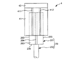
図10、図11に示すように、各挟持片41は、平面視で長方形をなす板部材で構成されている。また、各挟持片41の表側の面、すなわち、外側を向く面には、それぞれ、マーカー411、412が付されている。マーカー411、412は、それぞれ、挟持片41の長辺方向に沿って延在しており、挟持片41の幅方向に互いに離間して配置されている。なお、マーカー411、412は、例えば、印刷されたものであってもよいし、シール等のように貼り付けされたものであってもよい。
As shown in FIG. 1, the
As shown in FIGS. 10 and 11, each clamping
図10に示す状態では、第1ワーク20のマーカー204がエンドエフェクター4のマーカー411とマーカー412との間に位置し、かつ、マーカー204がマーカー411とマーカー412に平行である。このような位置関係は、「第1ワーク20がエンドエフェクター4に正常に挟持されている」とみなされる(判断される)。
一方、図11に示す状態では、第1ワーク20のマーカー204がエンドエフェクター4のマーカー411とマーカー412との間から外れ、さらに、マーカー204がマーカー411とマーカー412に対し傾斜している。このような位置関係は、「第1ワーク20がエンドエフェクター4に正常に挟持されていない」とみなされる。
In the state shown in FIG. 10, the
On the other hand, in the state shown in FIG. 11, the
支持部42は、例えば互いに噛み合う多数の歯車と、その駆動源としてのモーターとを有し、これらの歯車が連動して回動することにより、挟持片41同士の接近・離間を行なうことができる。なお、支持部42は、ロボットアーム2に装着される部分でもある。
また、本実施形態では、エンドエフェクター4は、第1ワーク20を支持しているが、これは、第1ワーク20が第2ワーク30よりも小さく、支持し易いものであるためである。従って、エンドエフェクター4は、第2ワーク30を支持することができれば、それでも構わない。
The
Further, in the present embodiment, the
図1に示すように、ロボットアーム2の最も先端側に位置するリンク21には、力検出部としての力覚センサー3が設置されている。装着状態で力覚センサー3は、当該リンク21とエンドエフェクター4との間に位置し、当該リンク21(ロボットアーム2)がエンドエフェクター4を介して受ける力やモーメント等の力情報を容易かつ確実に検出することができる。なお、以下では、力とモーメントとを含めて力と言う。
As shown in FIG. 1, a
この力覚センサー3の検出結果、すなわち、力覚センサー3から出力される信号は、制御装置10(パーソナルコンピューター11)に入力される。そして、制御装置10は、力覚センサー3の検出結果に基づいて所定の制御を行う。
なお、力覚センサー3としては、特に限定されず、各種のものを用いることができるが、その1例としては、互いに直交する3軸の各軸方向の力および各軸回りのモーメントを検出する6軸力センサー等が挙げられる。
The detection result of the
The
また、力覚センサー3の形状は、特に限定されないが、本実施形態では円盤状となっている。この円盤状をなす力覚センサー3は、中心軸がリンク21の長手方向に沿っている。
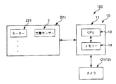
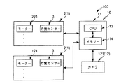
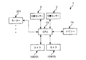
図9に示すように、制御装置10は、ロボット1と電気的に接続され、当該ロボット1を制御する装置である。制御装置10は、パーソナルコンピューター11と、撮像部12としてのカメラ121とを有している。
Further, the shape of the
As shown in FIG. 9, the
パーソナルコンピューター11は、CPU(Central Processing Unit)13と、メモリー(記録媒体)14とが内蔵されている。
CPU13は、各種処理を実行する機能を有している。その機能としては、例えば、ロボットアーム2の作動を制御する制御部としての機能、第1ワーク20と第2ワーク30との組立の良否判定を行なう良否判定部としての機能、第1ワーク20のマーカー204やエンドエフェクター4のマーカー411、412を抽出する抽出部としての機能等が挙げられる。
The
The
また、各種処理用の制御プログラムは、メモリー14に記憶されている。そして、CPU13は、実行すべき処理に応じて、該当する制御プログラムをメモリー14から呼び出す。
カメラ121は、ズーム機能を有するCCD(Charge Coupled Device)カメラである。カメラ121は、下方を向いて天井300に支持されており、第1ワーク20を支持したエンドエフェクター4を少なくとも含む、ロボット1の稼動領域全体を組立開始前と組立中に撮像して、撮像データーを得ることができる。
Control programs for various types of processing are stored in the
The
制御装置10では、CPU13は、ロボットアーム2に対してインピーダンス制御を行なうことができる。「インピーダンス制御」とは、ロボットアーム2に装着されたエンドエフェクター4に外力が加わったときに、当該エンドエフェクター4があたかも稼動領域内でばねやダンパーに支持されているかのように、ロボットアーム2をふるまわせる制御方法である(坪内孝司・大隅久・米田完著、「これならできるロボット創造設計」、第1刷、講談社、2007年2月10日、p.p.75−76)。そして、このときのばね定数、ダンパーの定数、ロボットアーム2(エンドエフェクター4)の見かけの質量を全て制御プログラム(ソフトウェア)上で指定することができる。
In the
このインピーダンス制御により、エンドエフェクター4に把持された第1ワーク20が、床面200上の第2ワーク30とぶつかったときにも、当該第2ワーク30とやわらかく接することができる。これにより、例えば、第1ワーク20や第2ワーク30の損傷を防止することができる。
また、CPU13は、撮像データーに対する画像処理を行ない、第1ワーク20のマーカー204やエンドエフェクター4のマーカー411、412を抽出することができる。このような処理は、まず、撮像データーとして、濃淡画像を得る。各図では、それぞれ、第1ワーク20のマーカー204と、エンドエフェクター4のマーカー411、412とが、色が濃い濃色領域となり、それ以外の部分が、色が淡い淡色領域となっている。そして、このような画像を二値化して、前記濃色領域を抽出して、マーカー204、411、412とする。
By this impedance control, even when the
Further, the
また、CPU13は、第1ワーク20と第2ワーク30との組立が行なわれている最中に、マーカー204、411、412の抽出結果に基づいて、当該組立の良否判定を行なうことができる。このような処理は、まず、組立中における、第1ワーク20のエンドエフェクター4に対する姿勢の変化量、すなわち、第1ワーク20の特徴点として抽出されたマーカー204と、エンドエフェクター4の特徴点として抽出されたマーカー411、412との位置関係がどの程度変化したのかを検出する。具体的には、マーカー204がマーカー411とマーカー412と間からどの程度位置ズレが生じ、どの程度マーカー411、412に対して傾いたのかを検出する。そして、この検出された変化量が閾値を超えなければ(図10に示す状態)良否判定を「良」とし、超えた場合に(図11に示す状態)良否判定を「否」とする。
Further, the
このような良否判定をすることができる理由としては、エンドエフェクター4が第1ワーク20を把持した直後(図2参照)の第1ワーク20のエンドエフェクター4に対する姿勢は、第1ワーク20の第2ワーク30への挿入完了まで(図5参照)そのまま維持されることとなるため、図10に示す状態で良否判定を「良」とすることができるからである。しかし、第1ワーク20を第2ワーク30に挿入しようとしたときに、第1ワーク20の突出部202が第2ワーク30の凹部302に挿入されず、側面301に衝突する場合がある(図6中の補助投影図参照)。この場合、第1ワーク20のエンドエフェクター4に対する姿勢は、エンドエフェクター4が第1ワーク20を把持した直後の姿勢から変化しているため、図11に示す状態で良否判定を「否」とすることができるからである。
The reason why such a quality determination can be made is that the posture of the
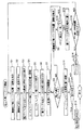
次に、第1ワーク20と第2ワーク30との組立用の制御プログラム(本発明に係る制御方法)について、図1〜図8、図10および図11を参照しつつ、図12に示すフローチャートに基づいて説明する。
まず、図1に示すように、ロボット1(ロボットアーム2)は、初期状態となっており、また、第1ワーク20および第2ワーク30は、それぞれ、所定位置に準備されている。この状態をカメラ121で撮像して、第1撮像データー(撮像データー)を得、当該第1撮像データーに基づいて、CPU13により、第2ワーク30の位置および姿勢を検出し(ステップS1)、第1ワーク20の位置および姿勢を検出する(ステップS2)。
Next, a control program (control method according to the present invention) for assembling the
First, as shown in FIG. 1, the robot 1 (robot arm 2) is in an initial state, and the
次に、ステップS1およびS2での検出結果に基づいて、CPU13により、第2ワーク30に対する第1ワーク20の最適な把持方法を選択する(ステップS3)。なお、把持方法は、予めメモリー14に複数種記憶されており、これらの中から選択することができる。
次に、図2に示すように、ロボット1を作動させて、ステップS3で選択された把持方法でエンドエフェクター4が第1ワーク20を把持可能な位置に、当該エンドエフェクター4を移動させ(ステップS4)、把持動作を行なわせる(ステップS5)。
Next, based on the detection results in steps S1 and S2, the
Next, as shown in FIG. 2, the
次に、第1撮像データーに基づいた位置制御により、図3に示すように、第1ワーク20と第2ワーク30との位置合わせを行なうように、すなわち、第1ワーク20の突出部202が第2ワーク30の凹部302に挿入可能な位置にまで接近するようにロボット1を作動させる(ステップS6)。
次に、力覚センサー3の検出結果に基づいた前記インピーダンス制御(力制御)により、図4に示すように、第1ワーク20と第2ワーク30との組立を開始して、そのまま継続していく、すなわち、当該組立が現に行なわれるようにロボット1を作動させる(ステップS7)。
Next, as shown in FIG. 3, the
Next, as shown in FIG. 4, the assembly of the
次に、第1ワーク20と第2ワーク30との組立が完了したか否かを判断する(ステップS8)。この判断は、例えば、ステップS7後にパーソナルコンピューター11に内蔵されているタイマー(図示せず)を作動させ、第1ワーク20の第2ワーク30に対する挿入が完了したとみなされる時間を経過したか否かで行なわれる。なお、この挿入完了時間は、例えば実験やシミュレーション等により既知となっており、予めメモリー14に記憶されている。
Next, it is determined whether or not the assembly of the
ステップS8の判断の結果、未だ組立が完了していないと判断されている場合には、カメラ121を作動させて第2撮像データー(撮像データー)を得、当該第2撮像データーに基づいて、CPU13により、第1ワーク20の位置および姿勢を検出する(ステップS9)。
次に、ステップS9での検出結果に基づいて、第1ワーク20と第2ワーク30との組立の良否判定を行なう(ステップS10)。この良否判定は、前述したように、図10に示す状態を良否判定「良」とし、図11に示す状態を良否判定「否」とする。
As a result of the determination in step S8, when it is determined that the assembly has not been completed yet, the
Next, it is determined whether or not the
ステップS10の判断の結果、良否判定が「良」の場合、組立が完了するまで当該組立を継続する。これにより、図5に示す状態となる。ステップS10を実行した後、ステップS8に戻り、組立が完了していないと判断される、すなわち、挿入完了時間の経過を迎える。
次に、エンドエフェクター4を作動させて、第1ワーク20を解放するとともに、ロボット1を作動させて、エンドエフェクター4を所定の退避位置まで移動させる(ステップS11)。
If the result of determination in step S10 is “good”, the assembly is continued until the assembly is completed. As a result, the state shown in FIG. 5 is obtained. After executing Step S10, the process returns to Step S8, where it is determined that the assembly is not completed, that is, the insertion completion time elapses.
Next, the
次に、得られた第1ワーク20と第2ワーク30との組立体40が良好か否かを判断する(ステップS12)。この判断は、例えば、テンプレートマッチングにより行なわれる。
ステップS12の判断の結果、組立体40が良好の場合、その旨の信号を例えばモニター(図示せず)に出力して(ステップS13)、オペレーター等に報知する。一方、組立体40が不良の場合、その旨のアラーム信号(音声)を出力して(ステップS14)、オペレーター等に報知する。
Next, it is determined whether or not the obtained
As a result of the determination in step S12, if the
また、図5に示す状態とならずに、図6に示す状態となると、ステップS10の判断の結果、良否判定が「否」となり、この場合、図7に示すように、ロボット1を作動させて、エンドエフェクター4に把持された第1ワーク20を載置ボックス50の凹部501上に移動させ、図8に示すように、そのまま解放する(ステップS15)。これにより、第1ワーク20が載置ボックス50に再度載置される。
In addition, when the state shown in FIG. 6 is obtained instead of the state shown in FIG. 5, the pass / fail judgment is “No” as a result of the judgment in step S10. In this case, the
次に、このステップS15が所定回数を超えたか否かを判断する(ステップS16)。ステップS16の判断の結果、前記所定回数を超えていない場合には、ステップS1に戻り、以後、それより下位のステップを順次実行する。これにより、組立が一旦中断され、エンドエフェクター4で第1ワーク20を把持し直して、第1ワーク20と第2ワーク30との組立を再度行なう(再開する)ことができる。一方、前記所定回数を超えた場合には、ステップS14を実行する。
Next, it is determined whether or not step S15 has exceeded a predetermined number of times (step S16). If the result of determination in step S16 is that the predetermined number of times has not been exceeded, the process returns to step S1, and thereafter, the lower steps are sequentially executed. As a result, the assembly is temporarily interrupted, the
このように、ロボットシステム100では、第1ワーク20と第2ワーク30との組立が行なわれている最中に、当該組立の良否判定を行なうことができる。これにより、組立が完了するまで、得られた組立体40が良好なものなのか、それとも、不良なものなのかが不明となるのを防止することができる、すなわち、第1ワーク20と第2ワーク30との組立の良否を迅速に把握することができる。そして、良否判定が良であれば、良品の組立体40をそのまま次の工程に移行することができ、良否判定が否であれば、組立を再度行なって、良品の組立体40を得ることができる。これにより、組立作業のタクトタイムや歩留まりの向上に寄与する。
Thus, in the
前述したように、カメラ121から得られる撮像データーとして、第1撮像データーと、第1撮像データーと異なるタイミングで得られた第2撮像データーとがある。第1撮像データーは、第1ワーク20と第2ワーク30との位置合わせを行なうときに用いられる撮像データーであり、第2撮像データーは、良否判定を行なうときに用いられる撮像データーである。このように、ロボットシステム100では、第1ワーク20と第2ワーク30との位置合わせを行なう処理と、組立の良否判定を行なう処理との各種処理条件に適した撮像データーを用いることができる。
また、第1撮像データーと第2撮像データーとは、カメラ121で得られている。これにより、1つのカメラ121を各種処理実行時に兼用することができ、よって、カメラ121の設置数を抑制することができる。
As described above, the imaging data obtained from the
The first image data and the second image data are obtained by the
<第2実施形態>
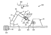
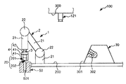
図13は、本発明に係るロボットシステム(制御装置)(第2実施形態)による第1ワークと第2ワークとの組み立て過程を示す側面図、図14は、図13に示すロボットシステムのブロック図である。
以下、これらの図を参照して本発明に係る制御装置、ロボット、ロボットシステムおよび制御方法の第2実施形態について説明するが、前述した実施形態との相違点を中心に説明し、同様の事項はその説明を省略する。
本実施形態は、ロボットアームの設置数が異なること以外は前記第1実施形態と同様である。
Second Embodiment
FIG. 13 is a side view showing the assembly process of the first workpiece and the second workpiece by the robot system (control device) according to the present invention (second embodiment), and FIG. 14 is a block diagram of the robot system shown in FIG. It is.
Hereinafter, the second embodiment of the control device, the robot, the robot system, and the control method according to the present invention will be described with reference to these drawings. However, the differences from the above-described embodiment will be mainly described and the same matters will be described. Will not be described.
The present embodiment is the same as the first embodiment except that the number of installed robot arms is different.
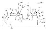
図13、図14に示すように、本実施形態では、ロボット1は、互いに離間して配置された2本のロボットアーム2を備えている。そして、図13中の左側のロボットアーム2に装着されたエンドエフェクター4で第1ワーク20を把持し、図13中の右側のロボットアーム2に装着されたエンドエフェクター4で第2ワーク30を把持することができる。なお、本実施形態では、第2ワーク30は、エンドエフェクター4で支持することができる程度の大きさの柱状の部材である。
このような構成により、第1ワーク20と第2ワーク30との組立を行なう際に、これらのワーク同士を互いに移動させて接近させることができ、よって、その組立を迅速に行なうことができる。
As shown in FIGS. 13 and 14, in the present embodiment, the
With such a configuration, when the
<第3実施形態>
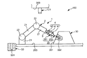
図15は、本発明に係るロボットシステム(制御装置)(第3実施形態)による第1ワークと第2ワークとの組み立て過程を示す側面図、図16は、図15に示すロボットシステムのブロック図である。
<Third Embodiment>
FIG. 15 is a side view showing the assembly process of the first workpiece and the second workpiece by the robot system (control device) according to the present invention (third embodiment), and FIG. 16 is a block diagram of the robot system shown in FIG. It is.
以下、これらの図を参照して本発明に係る制御装置、ロボット、ロボットシステムおよび制御方法の第3実施形態について説明するが、前述した実施形態との相違点を中心に説明し、同様の事項はその説明を省略する。
本実施形態は、カメラの設置数が異なること以外は前記第2実施形態と同様である。
図15、図16に示すように、本実施形態では、撮像部12は、カメラ121を第1カメラとして、その他に、第2カメラとしてのカメラ122と、第3カメラとしてのカメラ123とを有している。
Hereinafter, the third embodiment of the control device, the robot, the robot system, and the control method according to the present invention will be described with reference to these drawings. However, the difference from the above-described embodiment will be mainly described, and similar matters will be described. Will not be described.
The present embodiment is the same as the second embodiment except that the number of cameras installed is different.
As shown in FIGS. 15 and 16, in this embodiment, the
カメラ122は、各ロボットアーム2の最も先端側に位置するリンク21に、先端側を向くように支持されている。
また、2本のロボットアーム2の間には、作業台400が配置されている。この作業台400には、例えば組立体40を載置することができる。
そして、カメラ123は、作業台400上に、斜め上方を向くように支持されている。
このような構成により、組立状況に応じてカメラ121〜123のいずれかを切り換えて、ワーク同士の位置合わせや、組立の良否判定に用いることができる。
The
A work table 400 is disposed between the two
The
With such a configuration, any one of the
<第4実施形態>
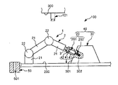
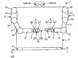
図17は、本発明に係るロボット(第4実施形態)による第1ワークと第2ワークとの組み立て過程を示す正面図、図18は、図17に示すロボットのブロック図である。
以下、これらの図を参照して本発明に係る制御装置、ロボット、ロボットシステムおよび制御方法の第4実施形態について説明するが、前述した実施形態との相違点を中心に説明し、同様の事項はその説明を省略する。
本実施形態は、ロボットの構成が異なること以外は前記第2実施形態と同様である。
<Fourth embodiment>
FIG. 17 is a front view showing the assembly process of the first workpiece and the second workpiece by the robot (fourth embodiment) according to the present invention, and FIG. 18 is a block diagram of the robot shown in FIG.
Hereinafter, the fourth embodiment of the control device, the robot, the robot system, and the control method according to the present invention will be described with reference to these drawings. However, the difference from the above-described embodiment will be mainly described, and similar matters will be described. Will not be described.
This embodiment is the same as the second embodiment except that the configuration of the robot is different.
図17に示すように、本実施形態では、ロボット1は、胴部5と、当該胴部5に回動可能に連結された2本のロボットアーム2とを有する人間型双腕ロボットである。胴部5には、CPU13やメモリー14が内蔵されている(図18参照)。
このような構成のロボット1は、図17中の左側のロボットアーム2に装着されたエンドエフェクター4で第1ワーク20を把持し、図17中の右側のロボットアーム2に装着されたエンドエフェクター4で第2ワーク30を把持することができる。これにより、第1ワーク20と第2ワーク30との組立を行なう際に、これらのワーク同士を互いに移動させて接近させることができ、よって、その組立を迅速に行なうことができる。
As shown in FIG. 17, in the present embodiment, the
The
また、胴部5の上部には、頭部に相当する部分に、撮像部12としての2つのカメラ124が並設されている。これにより、ステレオ視で、第1ワーク20と第2ワーク30との組立状態を確認することができる。
また、胴部5の下部には、複数のキャスター6が設置されている。これにより、例えばロボット1をその背面側から(図17中の紙面奥側から手前に向かって)押圧することにより、床面200上を移動させることができる。
以上、本発明に係る制御装置、ロボット、ロボットシステムおよび制御方法を図示の実施形態について説明したが、本発明は、これに限定されるものではなく、制御装置、ロボット、ロボットシステムを構成する各部は、同様の機能を発揮し得る任意の構成のものと置換することができる。また、任意の構成物が付加されていてもよい。
In addition, two
A plurality of casters 6 are installed at the lower part of the
The control device, the robot, the robot system, and the control method according to the present invention have been described above with respect to the illustrated embodiment. However, the present invention is not limited to this, and the control device, the robot, and each part constituting the robot system Can be replaced with any structure capable of performing the same function. Moreover, arbitrary components may be added.
また、本発明に係る制御装置、ロボット、ロボットシステムおよび制御方法は、前記各実施形態のうちの、任意の2以上の構成(特徴)を組み合わせたものであってもよい。
ロボットアームの本数は、第1実施形態では1本、第2実施形態〜第4実施形態では2本であったが、これに限定されず、3本以上であってもよい。
エンドエフェクターは、前記各実施形態では挟持によりワークを支持するよう構成されたものであるが、これに限定されず、例えば、吸着によりワークを支持するよう構成されたものであってもよい。
In addition, the control device, the robot, the robot system, and the control method according to the present invention may be a combination of any two or more configurations (features) of the above embodiments.
The number of robot arms is one in the first embodiment and two in the second to fourth embodiments, but is not limited to this and may be three or more.
The end effector is configured to support the workpiece by clamping in each of the embodiments described above, but is not limited thereto, and may be configured to support the workpiece by suction, for example.
また、第1ワークと第2ワークとの組立の良否判定を行なうときには、前記各実施形態では第1ワークのマーカーを特徴点として抽出していたが、これに限定されず、例えば、第1ワーク自体の溝やエッジ、これらとマーカーとの組み合わせたものを特徴点として抽出してもよい。これと同様に、第1ワークと第2ワークとの組立の良否判定を行なうときには、前記各実施形態ではエンドエフェクターのマーカーを特徴点として抽出していたが、これに限定されず、例えば、エンドエフェクター自体の溝やエッジ、これらとマーカーとの組み合わせたものを特徴点として抽出してもよい。 In addition, when determining whether or not the first work and the second work are assembled, the marker of the first work is extracted as a feature point in each of the above embodiments. However, the present invention is not limited to this. A groove or edge of itself, or a combination of these with a marker may be extracted as a feature point. Similarly, when determining the quality of the assembly of the first workpiece and the second workpiece, the marker of the end effector is extracted as the feature point in each of the above embodiments. However, the present invention is not limited to this. You may extract as a feature point the groove | channel and edge of effector itself, and the combination of these and a marker.
1……ロボット 2……ロボットアーム 21……リンク 22……関節 221……モーター 3……力覚センサー 4……エンドエフェクター 41……挟持片 411……マーカー 412……マーカー 42……支持部 5……胴部 6……キャスター 10……制御装置 11……パーソナルコンピューター 12……撮像部 121……カメラ 122……カメラ 123……カメラ 124……カメラ 13……CPU 14……メモリー 20……第1ワーク 201……基部 202……突出部 203……側面 204……マーカー 205……一端面 30……第2ワーク 40……組立体 50……載置ボックス 100……ロボットシステム 200……床面 300……天井 301……側面 302……凹部 400……作業台 501……凹部
1 ……
Claims (15)
前記ロボットアームの動きを制御する制御部と、
撮像データーを得る撮像部と、
を備え、
前記制御部は、組立開始前にエンドエフェクターを少なくとも含む領域を前記撮像部で撮像して前記ロボットアームを動作させ、組立開始後に、少なくとも前記力検出部から出力値が出力されている間前記ロボットアームを動作させ、さらに前記第1の物体と前記第2の物体の組立部を撮像することを特徴とする制御装置。 A control device for controlling a robot that assembles a first object and a second object, comprising an end effector, a robot arm, and a force detection unit provided between the robot arm and the end effector,
A control unit for controlling the movement of the robot arm;
An imaging unit for obtaining imaging data;
With
The controller picks up an area including at least an end effector with the image pickup unit before starting assembly and operates the robot arm, and after the start of assembly, at least while the output value is output from the force detector A control device characterized by operating an arm and imaging an assembly part of the first object and the second object.
前記良否判定部は前記撮像データーに基づいて前記良否判定を行ない、
前記良否判定が良の場合には、前記組立が完了するまで前記組立を継続する請求項1に記載の制御装置。 A pass / fail determination unit for determining pass / fail of the assembly;
The quality determination unit performs the quality determination based on the imaging data,
The control device according to claim 1, wherein when the quality determination is good, the assembly is continued until the assembly is completed.
前記変化量は、前記第1の物体および前記第2の物体の少なくとも一方の特徴点と、前記エンドエフェクターの特徴点との位置関係の変化である請求項4に記載の制御装置。 An extraction unit for extracting each feature point of at least one of the first object and the second object and the end effector;
The control device according to claim 4, wherein the change amount is a change in a positional relationship between at least one feature point of the first object and the second object and a feature point of the end effector.
前記カメラで前記第1撮像データーと前記第2撮像データーとを得る請求項6に記載の制御装置。 The imaging unit is composed of one camera,
The control device according to claim 6, wherein the first imaging data and the second imaging data are obtained by the camera.
前記ロボットアームと前記エンドエフェクターとの間に設けられて情報を検出する力検出部と、
前記エンドエフェクターを含む領域を撮像して、撮像データーを得る撮像部と、
前記撮像データーに基づいて前記ロボットアームを動作させて前記第1の物体と前記第2の物体との位置合わせを行ない、前記力検出部の検出結果に基づいて、前記ロボットアームを動作させて前記第1の物体と前記第2の物体との組立を行なう制御部と、
前記撮像データーに基づいて前記組立の良否判定を行なう良否判定部と、を備えることを特徴とするロボット。 A robot including a robot arm to which an end effector supporting at least one of the first object and the second object is mounted;
A force detector provided between the robot arm and the end effector for detecting information;
An imaging unit that captures imaging data by imaging an area including the end effector;
The robot arm is operated based on the imaging data to align the first object and the second object, and the robot arm is operated based on the detection result of the force detection unit. A control unit for assembling the first object and the second object;
And a quality determination unit that determines quality of the assembly based on the imaging data.
一方の前記ロボットアームに装着された前記エンドエフェクターで前記第1の物体を支持し、他方の前記ロボットアームに装着された前記エンドエフェクターで前記第2の物体を支持する請求項9に記載のロボット。 Two robot arms are provided,
The robot according to claim 9, wherein the first object is supported by the end effector attached to one of the robot arms, and the second object is supported by the end effector attached to the other robot arm. .
前記ロボットアームと前記エンドエフェクターとの間に設けられて前記エンドエフェクターが受ける力情報を検出する力検出部と、を備えて、
前記第1の物体と前記第2の物体を組み立てるロボットを制御する、請求項1ないし8のいずれか1項に記載の制御装置と、を備えることを特徴とするロボットシステム。 At least one robot arm to which an end effector supporting at least one of the first object and the second object is attached;
A force detection unit that is provided between the robot arm and the end effector and detects force information received by the end effector;
A robot system comprising: the control device according to claim 1, which controls a robot that assembles the first object and the second object.
一方の前記ロボットアームに装着された前記エンドエフェクターで前記第1の物体を支持し、他方の前記ロボットアームに装着された前記エンドエフェクターで前記第2の物体を支持する請求項12に記載のロボットシステム。 Two robot arms are provided,
The robot according to claim 12, wherein the first object is supported by the end effector attached to one of the robot arms, and the second object is supported by the end effector attached to the other robot arm. system.
前記第1の物体および前記第2の物体の少なくとも一方を支持した前記エンドエフェクターを含む領域を撮像した撮像データーに基づいて前記ロボットアームを動作させて前記第1の物体と前記第2の物体との位置合わせを行ない、前記ロボットアームと前記エンドエフェクターとの間に設けられた力検出部が検出する検出結果に基づいて、前記ロボットアームを動作させて前記第1の物体と前記第2の物体との組立を行なうとともに、前記撮像データーに基づいて、前記組立の良否判定を行なうことを特徴とする制御方法。 A control method for controlling a robot including a robot arm to which the end effector supporting at least one of a first object and a second object is attached,
The robot arm is operated based on imaging data obtained by imaging an area including the end effector that supports at least one of the first object and the second object, and the first object and the second object The first object and the second object are operated by operating the robot arm based on a detection result detected by a force detection unit provided between the robot arm and the end effector. And a control method for determining whether the assembly is good or not based on the imaging data.
Priority Applications (1)
| Application Number | Priority Date | Filing Date | Title |
|---|---|---|---|
| JP2014036401A JP2015160271A (en) | 2014-02-27 | 2014-02-27 | Control device, robot, robot system and control method |
Applications Claiming Priority (1)
| Application Number | Priority Date | Filing Date | Title |
|---|---|---|---|
| JP2014036401A JP2015160271A (en) | 2014-02-27 | 2014-02-27 | Control device, robot, robot system and control method |
Publications (1)
| Publication Number | Publication Date |
|---|---|
| JP2015160271A true JP2015160271A (en) | 2015-09-07 |
Family
ID=54183728
Family Applications (1)
| Application Number | Title | Priority Date | Filing Date |
|---|---|---|---|
| JP2014036401A Pending JP2015160271A (en) | 2014-02-27 | 2014-02-27 | Control device, robot, robot system and control method |
Country Status (1)
| Country | Link |
|---|---|
| JP (1) | JP2015160271A (en) |
Cited By (5)
| Publication number | Priority date | Publication date | Assignee | Title |
|---|---|---|---|---|
| JP2017100242A (en) * | 2015-12-02 | 2017-06-08 | グローリー株式会社 | Inspection robot system |
| JP2017136657A (en) * | 2016-02-02 | 2017-08-10 | 平田機工株式会社 | Pressing-in method and pressing-in system |
| JP2017205862A (en) * | 2016-05-19 | 2017-11-24 | ザ・ボーイング・カンパニーThe Boeing Company | Method and device for cooperatively operating independent automated systems |
| JP2018024049A (en) * | 2016-08-10 | 2018-02-15 | ファナック株式会社 | Robot control device for assembly robot |
| WO2021166941A1 (en) * | 2020-02-17 | 2021-08-26 | 川崎重工業株式会社 | Insertion goodness determiner, insertion goodness determination device, robot system, and insertion goodness determination method |
-
2014
- 2014-02-27 JP JP2014036401A patent/JP2015160271A/en active Pending
Cited By (12)
| Publication number | Priority date | Publication date | Assignee | Title |
|---|---|---|---|---|
| JP2017100242A (en) * | 2015-12-02 | 2017-06-08 | グローリー株式会社 | Inspection robot system |
| JP2017136657A (en) * | 2016-02-02 | 2017-08-10 | 平田機工株式会社 | Pressing-in method and pressing-in system |
| JP2017205862A (en) * | 2016-05-19 | 2017-11-24 | ザ・ボーイング・カンパニーThe Boeing Company | Method and device for cooperatively operating independent automated systems |
| JP6991722B2 (en) | 2016-05-19 | 2022-01-12 | ザ・ボーイング・カンパニー | How and equipment to coordinate independent automation systems |
| JP2018024049A (en) * | 2016-08-10 | 2018-02-15 | ファナック株式会社 | Robot control device for assembly robot |
| US10350758B2 (en) | 2016-08-10 | 2019-07-16 | Fanuc Corporation | Robot control unit for assembly robot |
| DE102017117928B4 (en) * | 2016-08-10 | 2020-10-01 | Fanuc Corporation | Robot control unit for an assembly robot |
| WO2021166941A1 (en) * | 2020-02-17 | 2021-08-26 | 川崎重工業株式会社 | Insertion goodness determiner, insertion goodness determination device, robot system, and insertion goodness determination method |
| JP2021126757A (en) * | 2020-02-17 | 2021-09-02 | 川崎重工業株式会社 | Insertion goodness determination device, insertion goodness determination device, robot system, and insertion goodness determination method. |
| CN114929429A (en) * | 2020-02-17 | 2022-08-19 | 川崎重工业株式会社 | Insertion quality determiner, insertion quality determining device, robot system, and insertion quality determining method |
| JP7395381B2 (en) | 2020-02-17 | 2023-12-11 | 川崎重工業株式会社 | Insertion quality determination device, insertion quality determination device, robot system, and insertion quality determination method. |
| CN114929429B (en) * | 2020-02-17 | 2024-04-05 | 川崎重工业株式会社 | Insertion success rate determination device, robot system, and insertion success rate determination method |
Similar Documents
| Publication | Publication Date | Title |
|---|---|---|
| JP5272617B2 (en) | Robot apparatus and control method of robot apparatus | |
| CN105291088B (en) | Robot, robot system and control method | |
| JP2015160271A (en) | Control device, robot, robot system and control method | |
| JP6322959B2 (en) | Robot, robot system, and robot controller | |
| JP5582126B2 (en) | Work take-out system, robot apparatus, and workpiece manufacturing method | |
| JP6361172B2 (en) | Robot, robot system, and control device | |
| US9802319B2 (en) | Robot, robot system, and control method | |
| JP2012223840A (en) | Robot system, and inspection method using robot system | |
| JP2009269110A (en) | Assembly equipment | |
| JP2009148845A (en) | Small-size production equipment | |
| JP2011000669A (en) | Robot system and article aligning method | |
| JP2012115915A (en) | Method of taking out workpiece | |
| JP7225725B2 (en) | Robotic system and insertion method | |
| JP2015226968A (en) | Robot, robot system, control unit and control method | |
| JP6528121B2 (en) | Component picking apparatus, component picking method and component mounting apparatus | |
| US20150343642A1 (en) | Robot, robot system, and control method | |
| WO2019239563A1 (en) | Robot system | |
| JP2004119046A (en) | Pin insertion device for connector | |
| JP2015150673A (en) | Control device, robot, robot system and control method | |
| WO2018074245A1 (en) | Wire harness manufacturing assistance device | |
| JP2018073495A (en) | Manufacturing support device for wire harness | |
| CN111278612A (en) | Component transfer device | |
| EP2177326A3 (en) | Method for aligning a workpiece to a robot | |
| JP2009184051A (en) | Pink lamp device and robot arm | |
| JP5544957B2 (en) | Camera detachable robot apparatus, work gripping system, and work gripping method |
Legal Events
| Date | Code | Title | Description |
|---|---|---|---|
| RD04 | Notification of resignation of power of attorney |
Free format text: JAPANESE INTERMEDIATE CODE: A7424 Effective date: 20160610 |
|
| RD03 | Notification of appointment of power of attorney |
Free format text: JAPANESE INTERMEDIATE CODE: A7423 Effective date: 20160624 |