JP2015157404A - Tire member formation device - Google Patents
Tire member formation device Download PDFInfo
- Publication number
- JP2015157404A JP2015157404A JP2014033191A JP2014033191A JP2015157404A JP 2015157404 A JP2015157404 A JP 2015157404A JP 2014033191 A JP2014033191 A JP 2014033191A JP 2014033191 A JP2014033191 A JP 2014033191A JP 2015157404 A JP2015157404 A JP 2015157404A
- Authority
- JP
- Japan
- Prior art keywords
- guide roller
- rubber strip
- supported
- conveyance
- transport
- Prior art date
- Legal status (The legal status is an assumption and is not a legal conclusion. Google has not performed a legal analysis and makes no representation as to the accuracy of the status listed.)
- Granted
Links
- 230000015572 biosynthetic process Effects 0.000 title abstract description 3
- 238000003825 pressing Methods 0.000 claims description 32
- 238000001125 extrusion Methods 0.000 claims description 4
- 238000000465 moulding Methods 0.000 claims 1
- 238000000034 method Methods 0.000 description 5
- 238000002788 crimping Methods 0.000 description 4
- 238000004804 winding Methods 0.000 description 4
- 230000037303 wrinkles Effects 0.000 description 2
- 241000842962 Apoda limacodes Species 0.000 description 1
- 238000010586 diagram Methods 0.000 description 1
- 230000003028 elevating effect Effects 0.000 description 1
- 238000009434 installation Methods 0.000 description 1
- 230000002093 peripheral effect Effects 0.000 description 1
Images


Classifications
-
- B—PERFORMING OPERATIONS; TRANSPORTING
- B29—WORKING OF PLASTICS; WORKING OF SUBSTANCES IN A PLASTIC STATE IN GENERAL
- B29D—PRODUCING PARTICULAR ARTICLES FROM PLASTICS OR FROM SUBSTANCES IN A PLASTIC STATE
- B29D30/00—Producing pneumatic or solid tyres or parts thereof
- B29D30/06—Pneumatic tyres or parts thereof (e.g. produced by casting, moulding, compression moulding, injection moulding, centrifugal casting)
- B29D30/08—Building tyres
- B29D30/20—Building tyres by the flat-tyre method, i.e. building on cylindrical drums
- B29D30/30—Applying the layers; Guiding or stretching the layers during application
-
- B—PERFORMING OPERATIONS; TRANSPORTING
- B29—WORKING OF PLASTICS; WORKING OF SUBSTANCES IN A PLASTIC STATE IN GENERAL
- B29B—PREPARATION OR PRETREATMENT OF THE MATERIAL TO BE SHAPED; MAKING GRANULES OR PREFORMS; RECOVERY OF PLASTICS OR OTHER CONSTITUENTS OF WASTE MATERIAL CONTAINING PLASTICS
- B29B11/00—Making preforms
- B29B11/06—Making preforms by moulding the material
- B29B11/10—Extrusion moulding
-
- B—PERFORMING OPERATIONS; TRANSPORTING
- B29—WORKING OF PLASTICS; WORKING OF SUBSTANCES IN A PLASTIC STATE IN GENERAL
- B29D—PRODUCING PARTICULAR ARTICLES FROM PLASTICS OR FROM SUBSTANCES IN A PLASTIC STATE
- B29D30/00—Producing pneumatic or solid tyres or parts thereof
- B29D30/06—Pneumatic tyres or parts thereof (e.g. produced by casting, moulding, compression moulding, injection moulding, centrifugal casting)
- B29D30/08—Building tyres
- B29D30/20—Building tyres by the flat-tyre method, i.e. building on cylindrical drums
- B29D30/30—Applying the layers; Guiding or stretching the layers during application
- B29D30/3028—Applying the layers; Guiding or stretching the layers during application by feeding a continuous band and winding it helically, i.e. the band is fed while being advanced along the drum axis, to form an annular element
-
- B—PERFORMING OPERATIONS; TRANSPORTING
- B29—WORKING OF PLASTICS; WORKING OF SUBSTANCES IN A PLASTIC STATE IN GENERAL
- B29D—PRODUCING PARTICULAR ARTICLES FROM PLASTICS OR FROM SUBSTANCES IN A PLASTIC STATE
- B29D30/00—Producing pneumatic or solid tyres or parts thereof
- B29D30/06—Pneumatic tyres or parts thereof (e.g. produced by casting, moulding, compression moulding, injection moulding, centrifugal casting)
- B29D30/52—Unvulcanised treads, e.g. on used tyres; Retreading
- B29D30/58—Applying bands of rubber treads, i.e. applying camel backs
- B29D30/60—Applying bands of rubber treads, i.e. applying camel backs by winding narrow strips
-
- B—PERFORMING OPERATIONS; TRANSPORTING
- B29—WORKING OF PLASTICS; WORKING OF SUBSTANCES IN A PLASTIC STATE IN GENERAL
- B29D—PRODUCING PARTICULAR ARTICLES FROM PLASTICS OR FROM SUBSTANCES IN A PLASTIC STATE
- B29D30/00—Producing pneumatic or solid tyres or parts thereof
- B29D30/06—Pneumatic tyres or parts thereof (e.g. produced by casting, moulding, compression moulding, injection moulding, centrifugal casting)
- B29D30/08—Building tyres
- B29D30/20—Building tyres by the flat-tyre method, i.e. building on cylindrical drums
- B29D30/30—Applying the layers; Guiding or stretching the layers during application
- B29D2030/3064—Details, accessories and auxiliary operations not otherwise provided for
- B29D2030/3085—Details, accessories and auxiliary operations not otherwise provided for the layers being applied being already cut to the appropriate length, before the application step
-
- B—PERFORMING OPERATIONS; TRANSPORTING
- B29—WORKING OF PLASTICS; WORKING OF SUBSTANCES IN A PLASTIC STATE IN GENERAL
- B29D—PRODUCING PARTICULAR ARTICLES FROM PLASTICS OR FROM SUBSTANCES IN A PLASTIC STATE
- B29D30/00—Producing pneumatic or solid tyres or parts thereof
- B29D30/06—Pneumatic tyres or parts thereof (e.g. produced by casting, moulding, compression moulding, injection moulding, centrifugal casting)
- B29D30/08—Building tyres
- B29D30/20—Building tyres by the flat-tyre method, i.e. building on cylindrical drums
- B29D30/24—Drums
Landscapes
- Engineering & Computer Science (AREA)
- Mechanical Engineering (AREA)
- Tyre Moulding (AREA)
Abstract
Description
本発明は、非直円筒状の被巻付け体の周囲に、ゴムストリップを精度良く貼り付けるタイヤ部材形成装置に関する。 The present invention relates to a tire member forming apparatus for attaching a rubber strip with high precision around a non-cylindrical body to be wound.
空気入りタイヤのゴム部材を形成する方法として、未加硫のゴムストリップを用いたストリップワインド工法が知られている。この工法では、タイヤ形成フォーマ等である被巻付け体の表面に、ゴムストリップをタイヤ周方向に連続的に巻き付けることにより、環状のゴム部材(例えば、トレッドゴムやサイドウォールゴム等)が形成される。ストリップワインド工法では、ゴムストリップの巻き付けピッチや巻き付け回数を変えることで、種々の断面形状を得ることができる。 As a method for forming a rubber member of a pneumatic tire, a strip wind method using an unvulcanized rubber strip is known. In this method, an annular rubber member (for example, a tread rubber or a sidewall rubber) is formed by continuously winding a rubber strip around the surface of a body to be wound, such as a tire forming former, in the tire circumferential direction. The In the strip wind method, various cross-sectional shapes can be obtained by changing the winding pitch and the number of windings of the rubber strip.
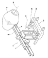
そして下記の特許文献1には、図9に示すように、ストリップワインド工法に用いられるゴムストリップの形成装置aが提案されている。この形成装置aは、例えば太鼓状等の非直円筒状の被巻付け体bの表面に、ゴムストリップGを精度良く貼り付けるものであって、ゴムストリップ搬送用の搬送コンベヤcを具えて構成される。
In
具体的には、形成装置aは、
(1)搬送コンベヤcを、被巻付け体bの軸心biと平行なX軸方向に沿って横移動させる横移動手段gxと、
(2)搬送コンベヤcを、Y軸方向に沿って被巻付け体bに向かって進退移動させる縦移動手段gyと、
(3)搬送コンベヤcを、垂直なZ軸方向の軸心Zi廻りで旋回させる旋回手段gzとを具える。
Specifically, the forming apparatus a
(1) lateral movement means gx for laterally moving the conveyor c along the X-axis direction parallel to the axis bi of the wound body b;
(2) Longitudinal moving means gy for moving the transport conveyor c forward and backward along the Y-axis direction toward the wound body b;
(3) A swiveling means gz for swiveling the conveyor c around an axis Zi in the vertical Z-axis direction.
これにより、被巻付け体bが非直円筒状のプロファイルを有する場合にも、搬送コンベヤcにおける搬送方向最前方側の案内ローラeを、プロファイルに合わせて自在に傾斜させることができる。そのためゴムストリップGに皺、不均一な伸び等の大きな歪みを招くことなく精度良く貼り付けることが可能となる。 Thereby, also when the to-be-wrapped body b has a non-straight cylindrical profile, the guide roller e on the forefront side in the transport direction of the transport conveyor c can be freely tilted according to the profile. Therefore, the rubber strip G can be attached with high accuracy without causing large distortion such as wrinkles and non-uniform elongation.
しかしながら構造のものは、長尺な搬送コンベヤc全体が、垂直な軸心Zi廻りで旋回する。そのため、旋回に大きなスペースが必要となり、他の形成装置を併設することが困難となる。しかも旋回半径内側の領域では、搬送コンベヤcとの衝突の恐れがあるため、作業者の作業領域を大きく制限する必要があり、作業効率に不利を招くという問題も生じる。 However, in the case of the structure, the entire long conveyer c turns around a vertical axis Zi. Therefore, a large space is required for turning, and it is difficult to install another forming apparatus. Moreover, in the area inside the turning radius, there is a risk of collision with the transport conveyor c, so that it is necessary to greatly limit the work area of the operator, and there is a problem in that the work efficiency is disadvantageous.
そこで発明は、装置の占有スペースを縮小でき、これによって他の形成装置の併設を可能としかつ作業者の作業領域の拡大を図りながら、非直円筒状の被巻付け体の表面に、ゴムストリップを精度良く貼り付けうるタイヤ部材形成装置を提供することを課題としている。 Therefore, the present invention can reduce the occupation space of the apparatus, thereby enabling the installation of another forming apparatus and expanding the work area of the operator, and the rubber strip on the surface of the non-cylindrical cylindrical wound body It is an object of the present invention to provide a tire member forming apparatus capable of attaching a tire with high accuracy.
本発明は、回転駆動される非直円筒状かつゴムストリップが巻付けられる被巻付け体を具えるドラム装置と、前記ゴムストリップを供給するゴムストリップ供給装置と、前記ゴムストリップ供給装置から供給される前記ゴムストリップを前記被巻付け体に搬送して巻き付けるアプリケータを具えるゴムストリップ貼付装置とを含むタイヤ部材形成装置であって、前記アプリケータは、複数の案内ローラによって周回可能に案内され、かつ搬送面上で前記ゴムストリップを搬送する搬送ベルトを有する搬送コンベヤを具え、しかも前記搬送面は、この搬送面の全長に亘って一直線状にのびる搬送面巾中心線を具えるとともに、前記案内ローラは、搬送方向最前方側に配される最前方側案内ローラを含む前方側の案内ローラと、搬送方向最後方側に配される最後方側案内ローラを含む後方側の案内ローラとに区分され、しかも前記前方側の案内ローラが、前記搬送面巾中心線廻りで傾動可能に保持されることより、前記搬送面は、前記前方側の案内ローラに支持される前方側の搬送面部と、前記後方側の案内ローラに支持される後方側の搬送面部との間に、捻れ可能な捻れ搬送面部を形成したことを特徴とする。 The present invention provides a drum device having a non-right cylindrical shape to be rotated and a wound body around which a rubber strip is wound, a rubber strip supply device for supplying the rubber strip, and a rubber strip supply device. A rubber strip applicator including an applicator that conveys and winds the rubber strip on the wound body, and the applicator is guided by a plurality of guide rollers so as to be able to go around. And a conveying conveyor having a conveying belt for conveying the rubber strip on the conveying surface, and the conveying surface has a conveying surface width center line extending linearly over the entire length of the conveying surface, and the guide The roller includes a front guide roller including a foremost guide roller disposed on the forefront side in the transport direction, and a rearmost side in the transport direction. It is divided into a rear side guide roller including a rearmost side guide roller, and the front side guide roller is held so as to be tiltable around the conveyance surface width center line. A torsionally conveying surface portion capable of being twisted is formed between a front conveying surface portion supported by the front guide roller and a rear conveying surface portion supported by the rear guide roller. To do.
本発明に係る前記タイヤ部材形成装置は、前記ゴムストリップ供給装置が、定量的にゴムを押出しうるギヤポンプと、前記ギヤポンプから押出された前記ゴムを予成形する押出しヘッドとを具えるゴム押出機を含むのが望ましい。 The tire member forming apparatus according to the present invention includes a rubber extruder in which the rubber strip supply device includes a gear pump that can quantitatively extrude rubber and an extrusion head that preforms the rubber extruded from the gear pump. It is desirable to include.
本発明に係る前記タイヤ部材形成装置は、前記後方側の案内ローラが、第1フレームに支持されるとともに、前記前方側の案内ローラは、前記第1フレームに前記搬送面巾中心線廻りで傾動可能に保持される第2フレームに支持されるのが望ましい。 In the tire member forming apparatus according to the present invention, the guide roller on the rear side is supported by the first frame, and the guide roller on the front side can tilt about the conveyance surface width center line on the first frame. It is desirable to be supported by the second frame held by the frame.
本発明に係る前記タイヤ部材形成装置は、前記アプリケータが、複数の上案内ローラによって周回可能に案内され、かつ前記ゴムストリップを前記搬送ベルトに押し付ける押付けベルトを有する押付けコンベヤを具えるとともに、前記押付けベルトが、前記ゴムストリップを前記前方側の搬送面部に押し付ける前方側の押付け面部と、前記後方側の搬送面部に押し付ける後方側の押付け面部と、前記捻れ搬送面部に押し付ける捻れ押付け面部とからなる押付け面を具えるのが望ましい。 The tire member forming apparatus according to the present invention includes a pressing conveyor in which the applicator is guided by a plurality of upper guide rollers so as to be able to go around, and has a pressing belt that presses the rubber strip against the conveying belt, The pressing belt includes a front pressing surface portion that presses the rubber strip against the front conveying surface portion, a rear pressing surface portion that presses against the rear conveying surface portion, and a twist pressing surface portion that presses against the twist conveying surface portion. It is desirable to have a pressing surface.
本発明に係る前記タイヤ部材形成装置は、前記ゴムストリップ供給装置が、前記被巻付け体の軸心と平行な方向に移動可能に支持された横移動台を有し、前記アプリケータは、前記横移動台に取り付けられるのが望ましい。 In the tire member forming apparatus according to the present invention, the rubber strip supply device includes a lateral movement base supported so as to be movable in a direction parallel to the axis of the wound body, and the applicator includes the It is desirable to be attached to a horizontal moving table.
本発明のタイヤ部材形成装置は、叙上の如く、ゴムストリップを搬送する搬送ベルトを有する搬送コンベヤを具えるとともに、搬送ベルトの搬送面は、その全長に亘って一直線状にのびる搬送面巾中心線を具える。 As described above, the tire member forming apparatus of the present invention includes a conveyor having a conveyor belt that conveys a rubber strip, and the conveyor surface of the conveyor belt extends in a straight line over the entire length thereof. With
又搬送ベルトを周回可能に支持する案内ローラを、搬送方向前方側の案内ローラと、搬送方向後方側の案内ローラとに区分したとき、前方側の案内ローラを、搬送面巾中心線廻りで傾動可能に保持している。これにより、搬送面は、前方側の案内ローラに支持される前方側の搬送面部と、後方側の案内ローラに支持される後方側の搬送面部との間に、捻れ可能な捻れ搬送面部を形成することができる。 In addition, when the guide roller that supports the conveyor belt in a rotatable manner is divided into a guide roller on the front side in the transport direction and a guide roller on the rear side in the transport direction, the front guide roller can be tilted around the center line of the transport surface width. Hold on. Thereby, the torsional conveyance surface part which can be twisted forms between the conveyance surface part of the front side supported by the guide roller of the front side, and the conveyance side part of the rear side supported by the guide roller of the back side. can do.
このような搬送コンベヤは、搬送面巾中心線廻りの傾動により、搬送方向最前方側案内ローラを、被巻付け体のプロファイルに合わせて自在に傾斜させることができる。そのため、ゴムストリップに皺、不均一な伸び等を招くことなく精度良く貼り付けることができる。しかも搬送面が、その全長に亘って一直線状にのびる搬送面巾中心線を具えるため、搬送方向最前方側案内ローラの傾動に追従しながら、ゴムストリップに長さ変化を生じさせることなく精度良く安定して搬送することができる。 Such a conveyor can tilt the guide roller at the foremost side in the conveyance direction according to the profile of the body to be wound by tilting around the center line of the conveyance surface. Therefore, it can be applied to the rubber strip with high accuracy without causing wrinkles or uneven elongation. In addition, since the conveyance surface has a conveyance surface width center line that extends in a straight line over its entire length, the rubber strip follows the tilt of the foremost guide roller in the conveyance direction and does not cause a change in the length of the rubber strip with high accuracy. It can be transported stably.
又搬送コンベヤが、垂直な軸心廻りで旋回するのではなく、搬送面巾中心線廻りで傾動するものである。そのため大きな旋回スペースが不要となって、装置占有スペースを縮小できる。これにより、他の形成装置の併設を可能にできる。又作業者の安全性を確保しながら作業領域を拡大することができ、貼付作業効率の向上にも貢献できる。 Further, the conveyor does not rotate around the vertical axis, but tilts around the center line of the conveyor surface. This eliminates the need for a large swiveling space and reduces the space occupied by the device. Thereby, other forming apparatuses can be provided side by side. In addition, the work area can be expanded while ensuring the safety of the worker, which can contribute to the improvement of the sticking work efficiency.
以下、本発明の実施の形態について、詳細に説明する。
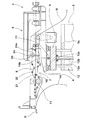
図1は、本発明の一実施形態のタイヤ部材形成装置Tの側面図である。図1に示されるように、タイヤ部材形成装置T(以下、単に「形成装置T」という場合がある。)は、未加硫のゴムストリップGが巻付けられるドラム装置1と、ゴムストリップGを供給するゴムストリップ供給装置2と、ゴムストリップ供給装置2から供給されるゴムストリップGをドラム装置1に貼付けるゴムストリップ貼付装置3とを含んでいる。
Hereinafter, embodiments of the present invention will be described in detail.
FIG. 1 is a side view of a tire member forming apparatus T according to an embodiment of the present invention. As shown in FIG. 1, a tire member forming apparatus T (hereinafter simply referred to as “forming apparatus T”) includes a
ドラム装置1は、回転駆動される被巻付け体1Aと、被巻付け体1Aを回転可能に支持する支持手段1Bとを具えている。
The
本例では、被巻付け体1Aがタイヤ形成フォーマであり、その周囲にゴムストリップGを巻き付けることにより、例えばトレッドゴム等であるゴム部材が形成される。被巻付け体1Aは、例えばタイヤ形状に合わせた太鼓状等の非直円筒状のプロファイルを具える。なおゴムストリップGとしては、内部にコードを埋設していても良く、かかる場合タイヤのバンド層が形成される。
In this example, the
ゴムストリップ供給装置2は、周知構造のものが採用され、本実施形態では、スクリューを有するゴム押出機2Aと、ゴム押出機2Aの吐出側に配されるローラヘッド2Bとを含んでいる。ゴム押出機2Aは、例えば、定量的にゴムを押出しうるギヤポンプ2aと、ギヤポンプ2aから押出されたゴムを予成形する押出しヘッド2bとを具えている。このゴム押出機2Aは、形成装置Tの形成サイクルに合わせて間欠的に作動し必要時のみゴムストリップGを形成する。このようなゴム押出機2Aによって、成形されるゴムストリップGは、比較的、高温かつ高粘性の状態で、被巻付け体1Aに供給される。従って、剛性の大きいタイヤ部材を製造することができる。
The rubber
ローラヘッド2Bは、スクリュー回転により混練りされかつゴム押出機2Aの押出しヘッド2bから押出される予成形ゴムをゴムストリップGに押出成形する一対のカレンダーローラを有している。本実施形態では、ローラヘッド2Bの下流側に、ゴムストリップGをU字に弛ませて保持するフェスツーンが設けられている。
The
本実施形態の形成装置Tに用いられるゴムストリップGは、例えば断面が、0.5〜4.0mm程度の厚さ及び5〜35mm程度の巾を有する長尺帯状のテープ状体である。 The rubber strip G used in the forming apparatus T of the present embodiment is a long strip-like tape-like body having a cross section with a thickness of about 0.5 to 4.0 mm and a width of about 5 to 35 mm.
ゴムストリップ貼付装置3(以下、単に「貼付装置3」という場合がある)は、ゴムストリップGを被巻付け体1Aに搬送して巻付けるアプリケータ4を具える。
貼付装置3は、本例では、基台5と、この基台5に上下移動可能に支持される昇降台9と、該昇降台9に横移動可能に支持される横移動台6とを含むとともに、この横移動台6に前記アプリケータ4が取り付く。前記昇降台9は、昇降手段12を介して上下動可能に支持される。本例の昇降手段12は、垂直な一対のガイド軸12aと、垂直なボールネジ軸12bとを含む。前記ガイド軸12aの上端は前記昇降台9に固定され、かつ下端は下板12cに固定される。又前記ボールネジ軸12bは前記昇降台9と下板12cとによって回転自在に枢支されるとともに、その下端部は、前記下板12cに取り付く昇降用モータM1に連結される。又前記基台5は、前記ガイド軸12aを挿通するガイド孔と前記ボールネジ軸12bに螺合するネジ孔とを有する支持板部5aを具える。
The rubber strip sticking device 3 (hereinafter sometimes simply referred to as “sticking device 3”) includes an applicator 4 that conveys and winds the rubber strip G around the
In this example, the sticking device 3 includes a
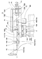
前記横移動台6は、本例では、横移動手段13を介して前記被巻付け体1Aの軸心1iと平行なX軸方向に移動可能に支持される。図2に示すように、本例の横移動手段13は、前記昇降台9に配されるX軸方向のガイドレール13aとボールネジ軸13bとを含むとともに、前記ボールネジ軸13bの一端は、昇降台9に取り付く横移動用モータ(図示しない。)に連結される。又前記横移動台6には、前記ガイドレール13aに案内されるガイド部とボールネジ軸13bに螺合するナット部とが設けられる。従って、アプリケータ4は、前記昇降用モータM1及び横移動用モータの駆動により、上下方向(Z軸方向)及び横方向(X軸方向)に自在に位置替えしうる。
In the present example, the lateral movement table 6 is supported via a lateral movement means 13 so as to be movable in the X-axis direction parallel to the axis 1i of the
次に、前記アプリケータ4は、前記横移動台6に一体移動可能に支持される搬送コンベヤ7を少なくとも具える。本例では前記アプリケータ4が、前記搬送コンベヤ7と、その上方に配される押付けコンベヤ8とを具える場合が示される。
Next, the applicator 4 includes at least a
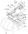
前記搬送コンベヤ7は、複数の案内ローラ10と、この案内ローラ10によって周回可能に案内される搬送ベルト11とを具える。図3、4に示すように、前記搬送ベルト11は、その上面を搬送面11Sとし、この搬送面11S上で前記ゴムストリップGを、ゴムストリップ供給装置2からの受取り位置P1から、被巻付け体1Aへの搬出位置P2まで搬送する。図5に概念的に示すように、前記搬送面11Sの巾中心は、搬送面11Sの全長に亘って一直線状にのびる。即ち、前記搬送面11Sは、その全長に亘って一直線状にのびる搬送面巾中心線11jを具える。
The
次に、前記複数の案内ローラ10は、搬送方向最前方側に配される最前方側案内ローラ10aを含む前方側の案内ローラ10Aと、搬送方向最後方側に配される最後方側案内ローラ10bを含む後方側の案内ローラ10Bとに区分される。そして、前記前方側の案内ローラ10Aは、前記搬送面巾中心線11j廻りで傾動可能に保持される。これにより前記搬送面11Sには、前記図5に示すように、前記前方側の案内ローラ10Aに支持される前方側の搬送面部11SAと、前記後方側の案内ローラ10Bに支持される後方側の搬送面部11SBとの間に、前記搬送面巾中心線11jの廻りで捻れ可能な捻れ搬送面部11SMが形成される。
Next, the plurality of
具体的には、アプリケータ4は、前記横移動台6に一体移動可能に固定される第1フレーム15と、この第1フレーム15に前記搬送面巾中心線11jの廻りで傾動可能に保持される第2フレーム16とを具える。
Specifically, the applicator 4 is held by the
前記第1フレーム15は、前記横移動台6の一側縁で立ち上がる側板状の基部15Aを有する。この基部15Aは、前記横移動台6の後端を越えて後方側にのびるとともに、該基部15Aの後端側には第2フレーム取付け用の取付け板部15Bが例えば水平に設けられる。そして前記基部15Aに、前記後方側の案内ローラ10Bが枢支される。
The
前記第2フレーム16は、前記搬送面巾中心線11jと同心な支軸17を有する。該支軸17は、前記取付け板部15Bに取り付く軸受けホルダ18によって、前記搬送面巾中心線11j廻りで回転可能に枢支される。又本例の第2フレーム16は、前記支軸17に固着される後板部16Aと、この後板部16Aの例えば上端から折れ曲がって前方側にのびる前板部16Bとを具えるとともに、この前板部16Bは、前端側に前記基部15Aと平行な側板状の側板部16B1を有する。そしてこの側板部16B1に、前記前方側の案内ローラ10Aが枢支される。
The
なお前記支軸17は、例えばステップモータ等の回転角度制御可能な駆動モータ(図示しない。)に連結される。又前記最後方側案内ローラ10bには、駆動モータM2が連結され、これによって前記搬送ベルト11が周回駆動される。
The
又前記第2フレーム16には、前方側の搬送面部11SA上でゴムストリップGを切断する切断手段19が配される。本例の切断手段19は、回転駆動される回転軸19Aと、その周面から半径方向外側にのびるカッタ刃19Bとを具える。この切断手段19は、前記カッタ刃19BがゴムストリップGと同速度で一回転することにより、ゴムストリップGを搬送しながら切断しうる。なお前記カッタ刃19Bの下方には、切断時の搬送ベルト11を下方から支える比較的大径の案内ローラ10A1が配される。
The
次に、前記押付けコンベヤ8は、図6に示すように、複数の上案内ローラ20と、この上案内ローラ20によって周回可能に案内される押付けベルト21とを具える。この押付けベルト21は、ゴムストリップGを前記搬送ベルト11に押し付け、これによりゴムストリップGの搬送ベルト11からの剥がれ、位置ずれ、スリップ等を防止する。前記押付けベルト21の押付け面21Sは、ゴムストリップGを前記前方側の搬送面部11SAに押し付ける前方側の押付け面部21SAと、前記後方側の搬送面部11SBに押し付ける後方側の押付け面部21SBと、捻れ搬送面部11SMに押し付ける捻れ押付け面部21SMとから形成される。
Next, as shown in FIG. 6, the
具体的には、前記上案内ローラ20は、搬送方向最前方側に配される最前方側上案内ローラ20aを含む前方側の上案内ローラ20Aと、搬送方向最後方側に配される最後方側上案内ローラ20bを含む後方側の上案内ローラ20Bとに区分される。そして後方側の上案内ローラ20Bは、後方側の案内ローラ10Bと同様、第1フレーム15の基部15Aに枢支される。又前方側の上案内ローラ20Aは、前方側の案内ローラ10Aと同様、第2フレーム16の側板部16B1に枢支される。
Specifically, the
又前記押付けベルト21は、本例では、前記切断手段19の後方側に配される後の押付けベルト21Bと、切断手段19の前方側に配される前の押付けベルト21Aとから形成される。
Further, in this example, the
又本例の貼付装置3は、前記搬送コンベヤ7の前方側に圧着手段22を具える。この圧着手段22は、被巻付け体1Aに貼り付けられたゴムストリップGを、該被巻付け体1Aに押し付けて圧着する。圧着手段22は、シリンダ22Aのロッド下端に、ホルダを介して枢支される圧着ローラ22Bを具える。前記シリンダ22Aは、第2フレーム16の側板部16B1に支持されるとともに、前記圧着ローラ22Bは、前記前方側の案内ローラ10Aと平行に枢着される。従って、圧着ローラ22Bは、前記搬送面巾中心線11j廻りで傾動可能であり、被巻付け体1Aのプロファイルに合わせて傾斜しゴムストリップGを圧着できる。
Further, the sticking device 3 of this example includes a crimping
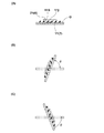
なお図7(A)に示すように、搬送コンベヤ7の搬送ベルト11は、ゴムストリップGよりも幅広であり、又押付けコンベヤ8の押付けベルト21は、ゴムストリップGよりも幅狭であるのが好ましい。又図7(B)、(C)に示すように、幅狭の押付けベルト21でゴムストリップGを押さえながら、ベルト11、21の長さも変化させずに旋回できる搬送面巾中心線11j廻りの旋回角度θは±80度程度である。従って本例では、前記旋回角度θを−80〜+80度の範囲としている。
As shown in FIG. 7A, the
図2に示されるように、本実施形態のアプリケータ4には、ストッパー23が設けられている。即ち、上述のように、アプリケータ4の第2フレーム16は、捻れ搬送面部11SMを設けるよう、搬送面巾中心線11jの廻りで傾動する。このため、案内ローラ10Aの開放側が下になる向きに傾動する場合、ストッパー23によって、案内ローラ10Aからの搬送ベルト11の脱落を抑制する。ストッパー23は、捻れ搬送面部11SMでの脱落を抑えるために、第2フレーム16の側板部16B1に設けられるのが好ましく、側板部16B1の前方側の案内ローラ10Aの搬送方向最後方側に配される後方ローラ10cよりも後方を支持するように設けられるのが、より好ましい。ストッパー23は、例えば、搬送ベルト11のみを支える態様でも良いが、本実施形態のように、搬送ベルト11及び押付けベルト21の両方を支える態様が望ましい。
As shown in FIG. 2, the applicator 4 of the present embodiment is provided with a
ストッパー23は、本実施形態では、案内ローラ10の回転軸と直交する向きにのびる円柱状の支持片24を有している。支持片24には、搬送ベルト11又は押付けベルト21をガイドする切り込み状のスリット24aが設けられている。
In this embodiment, the
本例の貼付装置3は、前述した如く、前記昇降台9及び横移動台6によりアプリケータ4を上下方向(Z軸方向)及び横方向(X軸方向)に位置替え自在に支持している。そのため、前記搬送面巾中心線11j廻りの旋回動作と協働することで、図8に示すように、ゴムストリップGを、非直円筒状の被巻付け体1Aの周囲に、そのプロファイルに合わせて精度良く貼り付けしうる。なお前記昇降台9及び横移動台6に代え、被巻付け体1Aを、アプリケータ4に対して上下方向(Z軸方向)及び横方向(X軸方向)に移動可能に支持することもできる。
As described above, the sticking device 3 of the present example supports the applicator 4 in the vertical direction (Z-axis direction) and the horizontal direction (X-axis direction) by the lift table 9 and the horizontal movement table 6 so that the position can be changed. . Therefore, by cooperating with the turning operation around the transport surface
以上、本発明の特に好ましい実施形態について詳述したが、本発明は図示の実施形態に限定されることなく、種々の態様に変形して実施しうる。 As mentioned above, although especially preferable embodiment of this invention was explained in full detail, this invention is not limited to embodiment of illustration, It can deform | transform and implement in a various aspect.
4 アプリケータ
7 搬送コンベヤ
10 案内ローラ
10A 前方側の案内ローラ
10B 後方側の案内ローラ
11 搬送ベルト
11S 搬送面
11j 搬送面巾中心線
11SA 前方側の搬送面部
11SB 後方側の搬送面部
11SM 捻れ搬送面部
4
Claims (5)
前記アプリケータは、複数の案内ローラによって周回可能に案内され、かつ搬送面上で前記ゴムストリップを搬送する搬送ベルトを有する搬送コンベヤを具え、
しかも前記搬送面は、この搬送面の全長に亘って一直線状にのびる搬送面巾中心線を具えるとともに、
前記案内ローラは、搬送方向最前方側に配される最前方側案内ローラを含む前方側の案内ローラと、搬送方向最後方側に配される最後方側案内ローラを含む後方側の案内ローラとに区分され、しかも前記前方側の案内ローラが、前記搬送面巾中心線廻りで傾動可能に保持されることより、前記搬送面は、前記前方側の案内ローラに支持される前方側の搬送面部と、前記後方側の案内ローラに支持される後方側の搬送面部との間に、捻れ可能な捻れ搬送面部を形成したことを特徴とするタイヤ部材形成装置。 A drum device having a non-cylindrical cylindrical shape and a wound body around which a rubber strip is wound, a rubber strip supply device for supplying the rubber strip, and the rubber strip supplied from the rubber strip supply device A rubber strip application device comprising an applicator that conveys and winds the object to the wound body,
The applicator includes a conveyance conveyor that is guided by a plurality of guide rollers so as to be able to go around and has a conveyance belt that conveys the rubber strip on a conveyance surface;
Moreover, the transport surface has a transport surface width center line extending linearly over the entire length of the transport surface,
The guide roller includes a front guide roller including a foremost guide roller disposed on the foremost side in the transport direction, and a rear guide roller including a rearmost guide roller disposed on the rearmost side in the transport direction. And the front guide roller is tiltably held around the transport surface width center line, so that the transport surface is supported by a front transport surface portion supported by the front guide roller. A tire member forming apparatus, characterized in that a torsional conveying surface part capable of being twisted is formed between the rear side conveying surface part supported by the rear side guide roller.
前記押付けベルトは、前記ゴムストリップを前記前方側の搬送面部に押し付ける前方側の押付け面部と、前記後方側の搬送面部に押し付ける後方側の押付け面部と、前記捻れ搬送面部に押し付ける捻れ押付け面部とからなる押付け面を具えることを特徴とする請求項1乃至3のいずれかに記載のタイヤ部材形成装置。 The applicator includes a pressing conveyor that is guided by a plurality of upper guide rollers and has a pressing belt that presses the rubber strip against the conveying belt.
The pressing belt includes a front pressing surface portion that presses the rubber strip against the front conveying surface portion, a rear pressing surface portion that presses against the rear conveying surface portion, and a twist pressing surface portion that presses against the twist conveying surface portion. The tire member forming apparatus according to claim 1, further comprising a pressing surface.
前記アプリケータは、前記横移動台に取り付けられることを特徴とする請求項1乃至4のいずれかに記載のタイヤ部材形成装置。 The rubber strip supply device has a lateral movement table supported so as to be movable in a direction parallel to the axis of the wound body,
The tire member forming apparatus according to claim 1, wherein the applicator is attached to the lateral movement table.
Priority Applications (5)
| Application Number | Priority Date | Filing Date | Title |
|---|---|---|---|
| JP2014033191A JP5945290B2 (en) | 2014-02-24 | 2014-02-24 | Tire member forming apparatus |
| US15/116,092 US10343360B2 (en) | 2014-02-24 | 2015-01-15 | Tire member-forming apparatus |
| PCT/JP2015/050860 WO2015125519A1 (en) | 2014-02-24 | 2015-01-15 | Tire member-forming apparatus |
| EP15751582.6A EP3106292B1 (en) | 2014-02-24 | 2015-01-15 | Tire member-forming apparatus |
| CN201580007702.5A CN105980141B (en) | 2014-02-24 | 2015-01-15 | Tyre element forms device |
Applications Claiming Priority (1)
| Application Number | Priority Date | Filing Date | Title |
|---|---|---|---|
| JP2014033191A JP5945290B2 (en) | 2014-02-24 | 2014-02-24 | Tire member forming apparatus |
Publications (2)
| Publication Number | Publication Date |
|---|---|
| JP2015157404A true JP2015157404A (en) | 2015-09-03 |
| JP5945290B2 JP5945290B2 (en) | 2016-07-05 |
Family
ID=53878035
Family Applications (1)
| Application Number | Title | Priority Date | Filing Date |
|---|---|---|---|
| JP2014033191A Expired - Fee Related JP5945290B2 (en) | 2014-02-24 | 2014-02-24 | Tire member forming apparatus |
Country Status (5)
| Country | Link |
|---|---|
| US (1) | US10343360B2 (en) |
| EP (1) | EP3106292B1 (en) |
| JP (1) | JP5945290B2 (en) |
| CN (1) | CN105980141B (en) |
| WO (1) | WO2015125519A1 (en) |
Cited By (1)
| Publication number | Priority date | Publication date | Assignee | Title |
|---|---|---|---|---|
| JP2021133655A (en) * | 2020-02-28 | 2021-09-13 | 住友ゴム工業株式会社 | Transport device |
Families Citing this family (4)
| Publication number | Priority date | Publication date | Assignee | Title |
|---|---|---|---|---|
| KR102202019B1 (en) * | 2014-08-27 | 2021-01-12 | 후지 세이코 가부시키가이샤 | Bead core forming device |
| CN108190641B (en) * | 2018-01-26 | 2024-06-04 | 联亚智能科技(苏州)有限公司 | Automatic winding machine set for rubber parts |
| CN108673918A (en) * | 2018-04-11 | 2018-10-19 | 联亚智能科技(苏州)有限公司 | A kind of winding unit with function of weighing |
| NL2029062B1 (en) * | 2021-08-26 | 2023-03-15 | Vmi Holland Bv | Strip applicator, strip-winding station and method for applying a strip to a strip-winding drum |
Citations (4)
| Publication number | Priority date | Publication date | Assignee | Title |
|---|---|---|---|---|
| JP2006110856A (en) * | 2004-10-14 | 2006-04-27 | Sumitomo Rubber Ind Ltd | Rubber strip sticking device |
| JP2006347003A (en) * | 2005-06-16 | 2006-12-28 | Bridgestone Corp | Manufacturing method of tire and belt forming apparatus |
| JP2011183698A (en) * | 2010-03-09 | 2011-09-22 | Sumitomo Rubber Ind Ltd | Method for manufacturing rubber member for tire, and manufacturing apparatus used therein |
| JP2013226677A (en) * | 2012-04-24 | 2013-11-07 | Bridgestone Corp | Apparatus and method for winding band-shaped member |
Family Cites Families (19)
| Publication number | Priority date | Publication date | Assignee | Title |
|---|---|---|---|---|
| US4233013A (en) * | 1978-05-16 | 1980-11-11 | The Firestone Tire & Rubber Company | Apparatus for producing continuous cured rubber strips |
| US4330116A (en) * | 1980-10-20 | 1982-05-18 | Newsome John R | Bundling mechanism for signatures |
| FR2603841B1 (en) | 1986-09-17 | 1989-02-24 | Michelin & Cie | METHOD OF MANUFACTURING A TIRE WITH LAYING RUBBER PRODUCTS AND REINFORCING ELEMENTS ON A SUPPORT, DEVICE FOR LAYING RUBBER PRODUCTS AND MACHINE USING SUCH DEVICE (S) |
| JP2783804B2 (en) * | 1988-02-10 | 1998-08-06 | 株式会社アマダ | Wire discharge device of wire cut electric discharge machine |
| US5335415A (en) * | 1991-10-30 | 1994-08-09 | Bridgestone Corporation | Apparatus for winding and pressure-fitting a small width strip to a rotating body |
| JP3194765B2 (en) * | 1991-11-13 | 2001-08-06 | 株式会社ブリヂストン | Narrow band winding device |
| JP4159801B2 (en) * | 2002-05-17 | 2008-10-01 | 株式会社ブリヂストン | Tire member molding apparatus and molding method |
| JP5129428B2 (en) * | 2003-12-01 | 2013-01-30 | インベンテイオ・アクテイエンゲゼルシヤフト | Elevator system |
| JP4673614B2 (en) * | 2004-12-02 | 2011-04-20 | 住友ゴム工業株式会社 | Manufacturing method of rubber member for tire |
| DE602005004581T2 (en) * | 2004-10-14 | 2009-01-29 | Sumitomo Rubber Industries Ltd., Kobe | Method and device for producing an article by winding a rubber strip on a support body |
| DE102005046115A1 (en) * | 2005-09-27 | 2007-03-29 | Continental Aktiengesellschaft | Apparatus for supplying and pressing rubber tapes or strips onto tire layer construction drum, includes frame-mounted rubber profiling device and endless rotating carrier for transporting the shaped material |
| JP4398936B2 (en) * | 2005-11-15 | 2010-01-13 | 住友ゴム工業株式会社 | Rubber strip sticking device |
| JP5121835B2 (en) * | 2007-09-05 | 2013-01-16 | 株式会社ブリヂストン | Method and apparatus for producing unvulcanized tire |
| JP5542121B2 (en) * | 2008-04-23 | 2014-07-09 | ピレリ・タイヤ・ソチエタ・ペル・アツィオーニ | Method and apparatus for building tires |
| WO2010065042A2 (en) * | 2008-12-05 | 2010-06-10 | Michelin Recherche Et Technique S.A. | Method and apparatus for forming a tire component upon an axially tapered surface |
| JP4922425B2 (en) * | 2010-03-19 | 2012-04-25 | 住友ゴム工業株式会社 | Rubber strip pressing device |
| FR2975040B1 (en) * | 2011-05-10 | 2013-06-28 | Michelin Soc Tech | TOOL FOR INSTALLING A BANDLET FOR REALIZING A PNEUMATIC BRAKE |
| JP6030910B2 (en) * | 2012-10-02 | 2016-11-24 | 住友ゴム工業株式会社 | Rubber member manufacturing equipment |
| JP5767623B2 (en) * | 2012-12-27 | 2015-08-19 | 住友ゴム工業株式会社 | Rubber strip sticking device |
-
2014
- 2014-02-24 JP JP2014033191A patent/JP5945290B2/en not_active Expired - Fee Related
-
2015
- 2015-01-15 US US15/116,092 patent/US10343360B2/en not_active Expired - Fee Related
- 2015-01-15 EP EP15751582.6A patent/EP3106292B1/en active Active
- 2015-01-15 CN CN201580007702.5A patent/CN105980141B/en not_active Expired - Fee Related
- 2015-01-15 WO PCT/JP2015/050860 patent/WO2015125519A1/en active Application Filing
Patent Citations (4)
| Publication number | Priority date | Publication date | Assignee | Title |
|---|---|---|---|---|
| JP2006110856A (en) * | 2004-10-14 | 2006-04-27 | Sumitomo Rubber Ind Ltd | Rubber strip sticking device |
| JP2006347003A (en) * | 2005-06-16 | 2006-12-28 | Bridgestone Corp | Manufacturing method of tire and belt forming apparatus |
| JP2011183698A (en) * | 2010-03-09 | 2011-09-22 | Sumitomo Rubber Ind Ltd | Method for manufacturing rubber member for tire, and manufacturing apparatus used therein |
| JP2013226677A (en) * | 2012-04-24 | 2013-11-07 | Bridgestone Corp | Apparatus and method for winding band-shaped member |
Cited By (2)
| Publication number | Priority date | Publication date | Assignee | Title |
|---|---|---|---|---|
| JP2021133655A (en) * | 2020-02-28 | 2021-09-13 | 住友ゴム工業株式会社 | Transport device |
| JP7476571B2 (en) | 2020-02-28 | 2024-05-01 | 住友ゴム工業株式会社 | Conveyor |
Also Published As
| Publication number | Publication date |
|---|---|
| CN105980141B (en) | 2019-01-01 |
| JP5945290B2 (en) | 2016-07-05 |
| US10343360B2 (en) | 2019-07-09 |
| EP3106292B1 (en) | 2019-05-29 |
| CN105980141A (en) | 2016-09-28 |
| EP3106292A1 (en) | 2016-12-21 |
| US20170165934A1 (en) | 2017-06-15 |
| WO2015125519A1 (en) | 2015-08-27 |
| EP3106292A4 (en) | 2017-11-22 |
Similar Documents
| Publication | Publication Date | Title |
|---|---|---|
| JP5945290B2 (en) | Tire member forming apparatus | |
| JP5767623B2 (en) | Rubber strip sticking device | |
| US9790050B2 (en) | Auto-adjustable wire precast system | |
| KR20200078313A (en) | Blanked refuse winding apparatus for continuous label paper | |
| JP6235862B2 (en) | Rubber strip sticking device | |
| JP6809026B2 (en) | Cutting method and equipment for corded rubber sheet members | |
| JP6013860B2 (en) | Rubber strip conveyor cutting device | |
| KR101181966B1 (en) | Roll roading apparatus | |
| JP2010058278A (en) | Extruder and method for manufacturing rubber roller | |
| CN213536216U (en) | Tensioning structure for transfer belt | |
| JP4673614B2 (en) | Manufacturing method of rubber member for tire | |
| JP6280374B2 (en) | Rubber strip pressing device | |
| KR20100013459A (en) | Resizing and cutting apparatus for wound manufactured good | |
| JP5620298B2 (en) | Rubber strip cutting device and cutting method | |
| JP2015199213A (en) | Winding method and device of belt-like member | |
| JPWO2003006350A1 (en) | Storage method for long plastic deformation member and storage device for long plastic deformation member | |
| JP4434760B2 (en) | Long thin rubber material sticking mechanism | |
| KR102017620B1 (en) | Angle of Belt Magnet Automatic Control Device for Belt Conveyor | |
| JP4040737B2 (en) | Spew trimming device | |
| JP6787062B2 (en) | Strip winding device | |
| JP2024010735A (en) | Cutting device of strip | |
| JP6431415B2 (en) | Rubber strip conveyor | |
| KR101415617B1 (en) | Bead winding unit | |
| JP2020093411A (en) | Method of producing tire member | |
| JP2015042456A (en) | Method and device of v-groove formation of strip member |
Legal Events
| Date | Code | Title | Description |
|---|---|---|---|
| A131 | Notification of reasons for refusal |
Free format text: JAPANESE INTERMEDIATE CODE: A131 Effective date: 20151104 |
|
| A521 | Request for written amendment filed |
Free format text: JAPANESE INTERMEDIATE CODE: A523 Effective date: 20151203 |
|
| TRDD | Decision of grant or rejection written | ||
| A01 | Written decision to grant a patent or to grant a registration (utility model) |
Free format text: JAPANESE INTERMEDIATE CODE: A01 Effective date: 20160517 |
|
| A61 | First payment of annual fees (during grant procedure) |
Free format text: JAPANESE INTERMEDIATE CODE: A61 Effective date: 20160527 |
|
| R150 | Certificate of patent or registration of utility model |
Ref document number: 5945290 Country of ref document: JP Free format text: JAPANESE INTERMEDIATE CODE: R150 |
|
| R250 | Receipt of annual fees |
Free format text: JAPANESE INTERMEDIATE CODE: R250 |
|
| LAPS | Cancellation because of no payment of annual fees |