JP2015152104A - slide bearing - Google Patents
slide bearing Download PDFInfo
- Publication number
- JP2015152104A JP2015152104A JP2014027004A JP2014027004A JP2015152104A JP 2015152104 A JP2015152104 A JP 2015152104A JP 2014027004 A JP2014027004 A JP 2014027004A JP 2014027004 A JP2014027004 A JP 2014027004A JP 2015152104 A JP2015152104 A JP 2015152104A
- Authority
- JP
- Japan
- Prior art keywords
- bearing
- oil groove
- peripheral surface
- inner peripheral
- downstream
- Prior art date
- Legal status (The legal status is an assumption and is not a legal conclusion. Google has not performed a legal analysis and makes no representation as to the accuracy of the status listed.)
- Pending
Links
Images


Abstract
Description
本発明は、一対の半円筒状軸受を組み合わせて形成され、軸部材を回転可能に支持する円筒状のすべり軸受の技術に関する。 The present invention relates to a technology of a cylindrical slide bearing formed by combining a pair of semicylindrical bearings and rotatably supporting a shaft member.
従来、一対の半円筒状軸受を組み合わせて形成され、軸部材を回転可能に支持する円筒状のすべり軸受の技術は公知となっている。例えば、特許文献1に記載の如くである。 Conventionally, a technique of a cylindrical slide bearing formed by combining a pair of semi-cylindrical bearings and rotatably supporting a shaft member has been publicly known. For example, as described in Patent Document 1.
特許文献1に記載の半割形状のすべり軸受(半円筒状軸受)は、内周面の両端部に形成されるクラッシュリリーフと、一方のクラッシュリリーフの近傍から他方のクラッシュリリーフの近傍に亘って形成される油溝と、当該油溝とクラッシュリリーフとの間に形成され、油溝内の潤滑油がクラッシュリリーフ内に流入することを阻止する流入阻止部と、を具備している。 The half-shaped slide bearing (semi-cylindrical bearing) described in Patent Document 1 includes a crush relief formed at both ends of the inner peripheral surface, and from the vicinity of one crush relief to the vicinity of the other crush relief. An oil groove is formed, and an inflow blocking portion is formed between the oil groove and the crush relief, and prevents the lubricating oil in the oil groove from flowing into the crush relief.
このように構成されたすべり軸受においては、油溝とクラッシュリリーフとが連通しないように流入阻止部によって遮られている。したがって、油溝からクラッシュリリーフを介してすべり軸受の外部へと漏れる潤滑油の量を低減することができる。これによって、油溝内の潤滑油をすべり軸受の内周面に十分に供給することができ、潤滑油量の不足による不具合(焼き付きや摩耗等)の発生を抑制することができる。 In the slide bearing configured as described above, the oil groove and the crush relief are blocked by the inflow blocking portion so as not to communicate with each other. Accordingly, it is possible to reduce the amount of lubricating oil leaking from the oil groove to the outside of the slide bearing through the crash relief. As a result, the lubricating oil in the oil groove can be sufficiently supplied to the inner peripheral surface of the slide bearing, and the occurrence of problems (such as seizure and wear) due to the insufficient amount of the lubricating oil can be suppressed.
しかしながら、特許文献1に記載の技術では、油溝内に異物が混入した場合、当該油溝とクラッシュリリーフとが連通されていないため、異物がすべり軸受の外部へと排出され難い。このため、すべり軸受の内周面(軸部材を受ける面)において、異物の混入を起因とする焼き付きが発生するおそれがある点で不利であった。 However, in the technique described in Patent Document 1, when a foreign matter is mixed in the oil groove, the oil groove and the crush relief are not communicated with each other, so the foreign matter is not easily discharged to the outside of the slide bearing. For this reason, it has been disadvantageous in that seizure due to mixing of foreign matters may occur on the inner peripheral surface (surface receiving the shaft member) of the slide bearing.
本発明は以上の如き状況に鑑みてなされたものであり、その解決しようとする課題は、油溝内の異物が外部へと排出されるように促すことが可能なすべり軸受を提供することである。 The present invention has been made in view of the situation as described above, and the problem to be solved is to provide a plain bearing capable of prompting foreign matter in the oil groove to be discharged to the outside. is there.
本発明の解決しようとする課題は以上の如くであり、次にこの課題を解決するための手段を説明する。 The problem to be solved by the present invention is as described above. Next, means for solving the problem will be described.
即ち、請求項1においては、上側に配置される上側半円筒状軸受及び下側に配置される下側半円筒状軸受を組み合わせて形成され、軸部材を回転可能に支持する円筒状のすべり軸受であって、前記下側半円筒状軸受は、当該下側半円筒状軸受の内周面のうち、前記軸部材の回転方向下流側の端部に形成される下側クラッシュリリーフと、前記下側クラッシュリリーフと連通するように、前記下側半円筒状軸受の内周面に形成される下側油溝と、を具備したものである。 That is, in claim 1, a cylindrical sliding bearing formed by combining an upper semi-cylindrical bearing disposed on the upper side and a lower semi-cylindrical bearing disposed on the lower side, and rotatably supporting the shaft member. The lower semi-cylindrical bearing includes a lower crush relief formed at an end of the inner circumferential surface of the lower semi-cylindrical bearing on the downstream side in the rotation direction of the shaft member, and the lower semi-cylindrical bearing. A lower oil groove formed on the inner peripheral surface of the lower semi-cylindrical bearing so as to communicate with the side crush relief.
請求項2においては、前記下側油溝は、前記下側半円筒状軸受の内周面のうち前記軸部材の回転方向下流側にのみ形成されるものである。 In the present invention, the lower oil groove is formed only on the downstream side in the rotation direction of the shaft member on the inner peripheral surface of the lower semi-cylindrical bearing.
請求項3においては、前記上側半円筒状軸受は、当該上側半円筒状軸受の内周面のうち、前記軸部材の回転方向上流側及び下流側の端部にそれぞれ形成される上側クラッシュリリーフと、前記上側クラッシュリリーフのうち一方から他方までを連通するように、前記上側半円筒状軸受の内周面に形成される上側油溝と、を具備したものである。
The upper semi-cylindrical bearing according to
本発明の効果として、以下に示すような効果を奏する。 As effects of the present invention, the following effects can be obtained.
請求項1においては、下側油溝内に混入した異物が、軸部材の回転に伴って下側クラッシュリリーフから外部へと排出されるのを促すことができる。これによって、すべり軸受の焼き付きの発生を抑制することができる。 According to the first aspect of the present invention, it is possible to prompt the foreign matter mixed in the lower oil groove to be discharged from the lower crash relief to the outside as the shaft member rotates. Thereby, the occurrence of seizure of the slide bearing can be suppressed.
請求項2においては、軸部材を受ける面を広く確保することができる。
In
請求項3においては、下側クラッシュリリーフで排出しきれなかった異物がある場合でも、当該異物を上側油溝を介して上側クラッシュリリーフから排出させることができる。 According to the third aspect, even when there is a foreign matter that could not be discharged by the lower crush relief, the foreign matter can be discharged from the upper crush relief through the upper oil groove.
以下の説明では、図中に示した矢印に従って、上下方向、前後方向及び左右方向を定義する。 In the following description, the vertical direction, the front-rear direction, and the left-right direction are defined according to the arrows shown in the drawing.
まず、図1を用いて、本発明に係るすべり軸受の一実施形態に係る主軸受2が設けられるクランクシャフト1に関する構成、及び当該クランクシャフト1に関する潤滑油供給機構の概略について説明する。 First, the structure regarding the crankshaft 1 provided with the main bearing 2 which concerns on one Embodiment of the slide bearing which concerns on this invention, and the outline of the lubricating oil supply mechanism regarding the said crankshaft 1 are demonstrated using FIG.
クランクシャフト1は内燃機関(エンジン)を構成する部材であり、ピストンの往復運動を回転運動に変換するためのものである。クランクシャフト1は、主としてクランクジャーナル1a、クランクアーム1b、クランクピン1c及び連通油路1dを具備する。
The crankshaft 1 is a member constituting an internal combustion engine (engine), and is used for converting the reciprocating motion of the piston into a rotational motion. The crankshaft 1 mainly includes a
クランクジャーナル1aは本発明に係る軸部材の実施の一形態であり、主軸受2を介してシリンダブロック3に回転可能に支持される。主軸受2には、その外周面と内周面とを連通する貫通孔14が形成される。クランクピン1cはクランクアーム1bを介してクランクジャーナル1aと連結される。クランクピン1cは、コンロッド軸受4を介してコンロッド5に回転可能に連結される。連通油路1dは、クランクジャーナル1aの外周面とクランクピン1cの外周面とを連通するように、クランクシャフト1内に形成される。
The
このような構成において、シリンダブロック3に形成された潤滑油路3cを介して、図示せぬメインオイルホールからの潤滑油が主軸受2へと供給される。さらに当該潤滑油は、主軸受2の貫通孔14を介して、当該主軸受2の内周面側へと供給される。当該潤滑油によって主軸受2とクランクジャーナル1aとの摺動面が潤滑される。
In such a configuration, lubricating oil from a main oil hole (not shown) is supplied to the main bearing 2 through a lubricating oil passage 3 c formed in the
主軸受2の内周面側へと供給された潤滑油は、さらに連通油路1dを介してクランクピン1cの外周面へと供給される。当該潤滑油によってクランクピン1cとコンロッド軸受4との摺動面が潤滑される。
The lubricating oil supplied to the inner peripheral surface side of the
以下では、図2を用いて、クランクジャーナル1aとシリンダブロック3との連結部(クランクジャーナル1aの支持部)の構成について説明する。
Below, the structure of the connection part (support part of the
シリンダブロック3は、本体側ハウジング3aと、当該本体側ハウジング3aの下部に固定されるキャップ3bとを具備する。本体側ハウジング3aの下端面には、正面視半円弧状に凹むように軸受部3dが形成されている。キャップ3bの上端面には、正面視半円弧状に凹むように軸受部3eが形成されている。当該軸受部3dと軸受部3eとの間にクランクジャーナル1aが挟み込まれるようにして支持される。この際、シリンダブロック3とクランクジャーナル1aとの間には主軸受2が介装される。
The
このような構成において、クランクジャーナル1aが回転(本実施形態においては、正面視時計回りに回転するものとする)すると、当該クランクジャーナル1aの外周面と主軸受2の内周面との間に、潤滑油路3cを介して供給される潤滑油の油膜が形成される。クランクジャーナル1aは、当該油膜を介して主軸受2に回転可能に支持される。
In such a configuration, when the
以下では、図2から図6までを用いて、主軸受2の構成について詳細に説明する。
Below, the structure of the
図2及び図3に示す主軸受2は、クランクジャーナル1aを回転可能に支持する円筒状のすべり軸受である。主軸受2は、一対の半円筒状軸受(アッパー側軸受10及びロア側軸受20)を具備する。アッパー側軸受10とロア側軸受20とを向かい合わせに上下に組み合わせることで、円筒状の主軸受2が形成される。
なお、以下の説明においては、アッパー側軸受10とロア側軸受20によって形成される円筒状の主軸受2の軸線(中心線)を軸線Cとする。
The
In the following description, the axis (center line) of the cylindrical
図3、図4及び図6(a)に示すアッパー側軸受10は、本発明に係る上側半円筒状軸受の実施の一形態であり、主軸受2のうち上半部を形成する部材である。アッパー側軸受10は半円筒状(円筒を、軸線を通る直径で切断した形状)に形成される。アッパー側軸受10は、その内周面を下方に向けた状態でシリンダブロック3の本体側ハウジング3aの軸受部3dに配置される(図2参照)。アッパー側軸受10は、主として上流側クラッシュリリーフ11、下流側クラッシュリリーフ12、油溝13及び貫通孔14を具備する。
An upper bearing 10 shown in FIGS. 3, 4, and 6 (a) is an embodiment of an upper semi-cylindrical bearing according to the present invention, and is a member that forms the upper half of the main bearing 2. . The
図3及び図4に示す上流側クラッシュリリーフ11及び下流側クラッシュリリーフ12は、本発明に係る上側クラッシュリリーフの実施の一形態であり、アッパー側軸受10の内周面を凹状に切り欠いて形成される部分である。上流側クラッシュリリーフ11は、アッパー側軸受10の左下端部(クランクジャーナル1aの回転方向上流側(以下、単に「上流側」と記す)の端部)に形成される。下流側クラッシュリリーフ12は、アッパー側軸受10の右下端部(クランクジャーナル1aの回転方向下流側(以下、単に「下流側」と記す)の端部)に形成される。アッパー側軸受10に上流側クラッシュリリーフ11及び下流側クラッシュリリーフ12を設けることで、当該アッパー側軸受10の両端部近傍において変形が生じた場合であっても、不具合(具体的には、変形した部分がクランクジャーナル1aに局部当たりすること)の発生を防止することができる。
The
図3、図4及び図6(a)に示す油溝13は、本発明に係る上側油溝の実施の一形態であり、アッパー側軸受10の内周面において潤滑油を案内すると共に、当該内周面において潤滑油を適宜貯溜するためのものである。油溝13は、アッパー側軸受10の内周面に形成される。油溝13は、アッパー側軸受10の円周方向に沿って延びるように形成される。油溝13の一端部(上流側の端部)は上流側クラッシュリリーフ11と連通される。油溝13の他端部(下流側の端部)は下流側クラッシュリリーフ12と連通される。すなわち、油溝13は上流側クラッシュリリーフ11と下流側クラッシュリリーフ12とを連通するように形成される。
The
油溝13は、アッパー側軸受10の前後中央部に形成される(図6(a)参照)。油溝13は、その全域に亘って前後方向に一定の幅となるように形成される。また、油溝13は、その全域に亘って一定の深さとなるように形成される。ここで、クランクジャーナル1aに形成された連通油路1dの開口部は、前後方向において油溝13と同一の位置に形成される。これによって、クランクジャーナル1aが回転して連通油路1dの開口部と油溝13とが対向した場合、当該油溝13内の潤滑油が連通油路1dを介してクランクピン1c(図1参照)へと供給される。
The
貫通孔14は、アッパー側軸受10の内周面(より詳細には、油溝13)と外周面とを連通するものである。貫通孔14は、アッパー側軸受10の左右中央部(上端部)に形成される。
The through
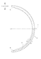
図3、図5及び図6(b)に示すロア側軸受20は、本発明に係る下側半円筒状軸受の実施の一形態であり、主軸受2のうち下半部を形成する部材である。ロア側軸受20は半円筒状に形成される。ロア側軸受20は、その内周面を上方に向けた状態でシリンダブロック3のキャップ3bの軸受部3eに配置される(図2参照)。ロア側軸受20は、主として上流側クラッシュリリーフ21、下流側クラッシュリリーフ22及び油溝23を具備する。
A
図3及び図5に示す上流側クラッシュリリーフ21及び下流側クラッシュリリーフ22は、ロア側軸受20の内周面を凹状に切り欠いて形成される部分である。上流側クラッシュリリーフ21は、ロア側軸受20の右上端部(上流側の端部)に形成される。下流側クラッシュリリーフ22は、本発明に係る下側クラッシュリリーフの実施の一形態であり、ロア側軸受20の左上端部(下流側の端部)に形成される。ロア側軸受20に上流側クラッシュリリーフ21及び下流側クラッシュリリーフ22を設けることで、当該ロア側軸受20の両端部近傍において変形が生じた場合であっても、不具合(具体的には、変形した部分がクランクジャーナル1aに局部当たりすること)の発生を防止することができる。
The upstream
図3、図5及び図6(b)に示す油溝23は、本発明に係る下側油溝の実施の一形態であり、ロア側軸受20の内周面において潤滑油を案内すると共に、当該内周面において潤滑油を適宜貯溜するためのものである。油溝23は、ロア側軸受20の内周面に形成される。油溝23は、ロア側軸受20の円周方向に沿って延びるように形成される。油溝23は、ロア側軸受20の内周面の左右中央よりも下流側(図5において、軸線Cから鉛直下方に引いた直線Vよりも左側)に形成される。具体的には、油溝23の一端部(上流側の端部)はロア側軸受20の内周面の左右中央部(下端部)に位置するように形成される。油溝23の他端部(下流側の端部)は下流側クラッシュリリーフ22と連通される。
The
油溝23は、ロア側軸受20の前後中央部に形成される(図6(b)参照)。この際、クランクジャーナル油溝23は、その全域に亘って前後方向に一定の幅となるように形成される。また、油溝23は、その全域に亘って一定の深さとなるように形成される。ここで、クランクジャーナル1aに形成された連通油路1dの開口部は、前後方向において油溝23と同一の位置に形成される。これによって、クランクジャーナル1aが回転して連通油路1dの開口部と油溝23とが対向した場合、当該油溝23内の潤滑油が連通油路1dを介してクランクピン1c(図1参照)へと供給される。
The
以下では、図3を用いて、アッパー側軸受10及びロア側軸受20における潤滑油の流れについて説明する。
Hereinafter, the flow of the lubricating oil in the upper side bearing 10 and the
貫通孔14を介して外部からアッパー側軸受10の内周面(油溝13)へと供給された潤滑油は、重力やクランクジャーナル1aの回転に伴って当該油溝13内を下方へと流通する。特に、正面視時計回りに回転するクランクジャーナル1aによって、当該潤滑油は油溝13内を正面視時計回りに流通する。油溝13内を流通する潤滑油の一部がアッパー側軸受10とクランクジャーナル1aとの摺動面に供給され、当該摺動面に油膜を形成する。
Lubricating oil supplied from the outside to the inner peripheral surface (oil groove 13) of the
油溝13の端部(特に、下流側の端部)まで流通した潤滑油の一部は、下流側クラッシュリリーフ12を介してアッパー側軸受10(主軸受2)の外部へと排出される。また、その他の潤滑油は、下流側クラッシュリリーフ12及び上流側クラッシュリリーフ21を介してロア側軸受20の内周面へと供給される。当該潤滑油によって、ロア側軸受20とクランクジャーナル1aとの摺動面に油膜が形成される。当該潤滑油は、クランクジャーナル1aの回転に伴ってロア側軸受20と当該クランクジャーナル1aとの摺動面を正面視時計回りに流通する。当該潤滑油の一部は、ロア側軸受20の油溝23へと供給される。油溝23内の潤滑油は、クランクジャーナル1aの回転によって、当該油溝23内を正面視時計回りに流通する。
A part of the lubricating oil flowing to the end of the oil groove 13 (particularly, the end on the downstream side) is discharged to the outside of the upper bearing 10 (main bearing 2) via the
油溝23の端部(下流側の端部)まで流通した潤滑油の一部は、下流側クラッシュリリーフ22を介してロア側軸受20(主軸受2)の外部へと排出される。また、その他の潤滑油は、下流側クラッシュリリーフ22及び上流側クラッシュリリーフ11を介してアッパー側軸受10の内周面(油溝13)へと供給される。
A part of the lubricating oil flowing to the end portion (downstream end portion) of the
ここで、潤滑油の中には、塵挨や金属摩耗によって発生した粉等の異物が混入する場合がある。異物がクランクジャーナル1aと主軸受2との摺動面に入り込むと、当該異物を起因とする焼き付きが発生するおそれがある。
Here, foreign matters such as dust or powder generated by metal wear may be mixed in the lubricating oil. If foreign matter enters the sliding surface between the
本実施形態においては、図7に示すように、油溝23内の潤滑油に混入した異物Sは、潤滑油と共に油溝23内を正面視時計回りに流通する。当該異物Sは、潤滑油と共に下流側クラッシュリリーフ22を介してロア側軸受20の外部へと排出される。このように、ロア側軸受20の油溝23の下流側の端部を下流側クラッシュリリーフ22と連通することによって、異物Sの外部への排出を促すことができ、ひいては主軸受2の焼き付きの発生を抑制することができる。
In the present embodiment, as shown in FIG. 7, the foreign matter S mixed in the lubricating oil in the
また、異物Sが下流側クラッシュリリーフ22から外部へと排出されることなく、上流側クラッシュリリーフ11を介してアッパー側軸受10の油溝13へと供給された場合であっても、当該異物Sは潤滑油と共に油溝13を下流側へと流通する。そして、当該異物Sは、潤滑油と共に油溝13の下流側の端部から下流側クラッシュリリーフ12を介して外部へと排出される(図3等参照)。このように、ロア側軸受20の下流側クラッシュリリーフ22から排出することができなかった異物Sも、アッパー側軸受10の下流側クラッシュリリーフ12から排出することができる。
Even when the foreign matter S is supplied to the
以上の如く、本実施形態に係る主軸受2(すべり軸受)は、上側に配置されるアッパー側軸受10(上側半円筒状軸受)及び下側に配置されるロア側軸受20(下側半円筒状軸受)を組み合わせて形成され、クランクジャーナル1a(軸部材)を回転可能に支持する円筒状の主軸受2であって、ロア側軸受20は、当該ロア側軸受20の内周面のうち、クランクジャーナル1aの回転方向下流側の端部に形成される下流側クラッシュリリーフ22(下側クラッシュリリーフ)と、下流側クラッシュリリーフ22と連通するように、ロア側軸受20の内周面に形成される油溝23(下側油溝)と、を具備するものである。
As described above, the main bearing 2 (slide bearing) according to the present embodiment includes the upper side bearing 10 (upper semicylindrical bearing) disposed on the upper side and the lower side bearing 20 (lower semicylindrical) disposed on the lower side. A cylindrical
このように構成することにより、油溝23内に混入した異物が、クランクジャーナル1aの回転に伴って下流側クラッシュリリーフ22から外部へと排出されるのを促すことができる。これによって、主軸受2の焼き付きの発生を抑制することができる。
また、本実施形態の如くクランクジャーナル1aからクランクピン1cへと潤滑油を供給する場合、クランクジャーナル1aを支持する主軸受2において異物の排出を促すことで、クランクピン1cへと供給される異物の量を低減することができる。これによって、クランクピン1c(コンロッド軸受4)における焼き付きの発生を抑制することができる。
また、下流側クラッシュリリーフ22から潤滑油が外部へと排出されるのを促すことができ、油溝23内の潤滑油の温度の上昇を抑制することができる。これによって、潤滑油の温度上昇による焼き付きの発生を抑制することができる。
With this configuration, it is possible to urge the foreign matter mixed in the
Further, when the lubricating oil is supplied from the
Further, it is possible to urge the lubricating oil to be discharged from the downstream
また、油溝23は、ロア側軸受20の内周面のうちクランクジャーナル1aの回転方向下流側(図5における直線Vよりも左側)にのみ形成されるものである。
The
このように構成することにより、クランクジャーナル1aを受ける面を広く確保することができる。すなわち、クランクジャーナル1aと摺接するロア側軸受20の内周面の面積を極力広くなるように確保することで、十分な荷重を支持することができる。
By comprising in this way, the surface which receives the
また、アッパー側軸受10は、当該アッパー側軸受の内周面のうち、クランクジャーナル1aの回転方向上流側及び下流側の端部にそれぞれ形成される上流側クラッシュリリーフ11及び下流側クラッシュリリーフ12(上側クラッシュリリーフ)と、前記上側クラッシュリリーフのうち一方(上流側クラッシュリリーフ11)から他方(下流側クラッシュリリーフ12)までを連通するように、アッパー側軸受10の内周面に形成される油溝13(上側油溝)と、を具備するものである。
Further, the upper side bearing 10 includes an upstream
このように構成することにより、下流側クラッシュリリーフ22で排出しきれなかった異物Sがある場合でも、当該異物Sを油溝13を介して下流側クラッシュリリーフ12から排出させることができる。これによって、主軸受2の焼き付きの発生をより効果的に抑制することができる。
By configuring in this way, even when there is a foreign matter S that could not be discharged by the
また、本実施形態は、クランクジャーナル1aの外周面とクランクピン1cの外周面とを連通し、クランクジャーナル1aの外周面からクランクピン1cの外周面へと潤滑油を案内する連通油路1dを有するクランクシャフト1を具備し、主軸受2によってクランクジャーナル1aが回転可能に支持されることを特徴とする潤滑油供給機構を含んでいる。
Further, in the present embodiment, a
このように構成することにより、クランクピン1cへと供給される潤滑油に含まれる異物Sの量を減少させることができる。これによって、クランクピン1cの焼き付きの発生を抑制することができる。
By comprising in this way, the quantity of the foreign material S contained in the lubricating oil supplied to the
なお、本実施形態においては、本発明に係るすべり軸受をクランクジャーナル1aを回転可能に支持する主軸受2に適用した例を示したが、本発明はこれに限るものではない。すなわち、本発明は、その他のすべり軸受(例えば、クランクピン1cとコンロッド5との間に介装されるコンロッド軸受4)に適用することも可能である。
In the present embodiment, the slide bearing according to the present invention is applied to the
また、本実施形態においては、ロア側軸受20の油溝23は、当該ロア側軸受20の内周面の左右中央部から下流側クラッシュリリーフ22に亘って形成されるものとしたが、本発明はこれに限るものではない。すなわち、油溝23は、下流側クラッシュリリーフ22に連通されていれば、その長さを限定するものではない。例えば、油溝23を本実施形態よりも短く形成することで、クランクジャーナル1aを受ける面をより広く確保することができる。
In the present embodiment, the
1 クランクシャフト
1a クランクジャーナル(軸部材)
2 主軸受(すべり軸受)
10 アッパー側軸受(上側半円筒状軸受)
11 上流側クラッシュリリーフ(上側クラッシュリリーフ)
12 下流側クラッシュリリーフ(上側クラッシュリリーフ)
13 油溝(上側油溝)
20 ロア側軸受(下側半円筒状軸受)
22 下流側クラッシュリリーフ(下側クラッシュリリーフ)
23 油溝(下側油溝)
1
2 Main bearing (slide bearing)
10 Upper bearing (upper semi-cylindrical bearing)
11 Upstream crash relief (upper crash relief)
12 Downstream crash relief (upper crash relief)
13 Oil groove (upper oil groove)
20 Lower bearing (lower semi-cylindrical bearing)
22 Downstream crash relief (lower crash relief)
23 Oil groove (lower oil groove)
Claims (3)
前記下側半円筒状軸受は、
当該下側半円筒状軸受の内周面のうち、前記軸部材の回転方向下流側の端部に形成される下側クラッシュリリーフと、
前記下側クラッシュリリーフと連通するように、前記下側半円筒状軸受の内周面に形成される下側油溝と、
を具備することを特徴とするすべり軸受。 A cylindrical sliding bearing formed by combining an upper semi-cylindrical bearing disposed on the upper side and a lower semi-cylindrical bearing disposed on the lower side, and rotatably supporting the shaft member,
The lower semi-cylindrical bearing is
Of the inner peripheral surface of the lower semi-cylindrical bearing, a lower crush relief formed at an end portion on the downstream side in the rotation direction of the shaft member,
A lower oil groove formed on an inner peripheral surface of the lower semi-cylindrical bearing so as to communicate with the lower crash relief;
A slide bearing characterized by comprising:
前記下側半円筒状軸受の内周面のうち前記軸部材の回転方向下流側にのみ形成されることを特徴とする、
請求項1に記載のすべり軸受。 The lower oil groove is
Of the inner peripheral surface of the lower semi-cylindrical bearing is formed only on the downstream side in the rotational direction of the shaft member,
The plain bearing according to claim 1.
当該上側半円筒状軸受の内周面のうち、前記軸部材の回転方向上流側及び下流側の端部にそれぞれ形成される上側クラッシュリリーフと、
前記上側クラッシュリリーフのうち一方から他方までを連通するように、前記上側半円筒状軸受の内周面に形成される上側油溝と、
を具備することを特徴とする、
請求項1又は請求項2に記載のすべり軸受。
The upper semi-cylindrical bearing is
Of the inner peripheral surface of the upper semi-cylindrical bearing, upper crush reliefs formed respectively on the upstream and downstream ends of the rotation direction of the shaft member,
An upper oil groove formed on an inner peripheral surface of the upper semi-cylindrical bearing so as to communicate from one to the other of the upper crush reliefs;
Characterized by comprising:
The plain bearing according to claim 1 or 2.
Priority Applications (5)
| Application Number | Priority Date | Filing Date | Title |
|---|---|---|---|
| JP2014027004A JP2015152104A (en) | 2014-02-14 | 2014-02-14 | slide bearing |
| CN201580007997.6A CN105980719B (en) | 2014-02-14 | 2015-02-04 | Sliding bearing and the lubricating oil feed mechanism for having the sliding bearing |
| PCT/JP2015/053131 WO2015122331A1 (en) | 2014-02-14 | 2015-02-04 | Plain bearing and lubricant supply mechanism equipped with same |
| US15/112,385 US10006484B2 (en) | 2014-02-14 | 2015-02-04 | Slide bearing and lubricant feed mechanism having the same |
| EP15749307.3A EP3106693B1 (en) | 2014-02-14 | 2015-02-04 | Plain bearing and lubricant supply mechanism equipped with same |
Applications Claiming Priority (1)
| Application Number | Priority Date | Filing Date | Title |
|---|---|---|---|
| JP2014027004A JP2015152104A (en) | 2014-02-14 | 2014-02-14 | slide bearing |
Publications (1)
| Publication Number | Publication Date |
|---|---|
| JP2015152104A true JP2015152104A (en) | 2015-08-24 |
Family
ID=53894599
Family Applications (1)
| Application Number | Title | Priority Date | Filing Date |
|---|---|---|---|
| JP2014027004A Pending JP2015152104A (en) | 2014-02-14 | 2014-02-14 | slide bearing |
Country Status (1)
| Country | Link |
|---|---|
| JP (1) | JP2015152104A (en) |
Cited By (5)
| Publication number | Priority date | Publication date | Assignee | Title |
|---|---|---|---|---|
| JP2017172723A (en) * | 2016-03-24 | 2017-09-28 | 大豊工業株式会社 | Slide bearing |
| WO2018105736A1 (en) * | 2016-12-09 | 2018-06-14 | 大豊工業株式会社 | Halved bearing |
| JP2019049272A (en) * | 2017-09-07 | 2019-03-28 | 大同メタル工業株式会社 | Main bearing for crank shaft of internal combustion engine |
| CN109983241A (en) * | 2016-10-31 | 2019-07-05 | 大丰工业株式会社 | Half-and-half bearing |
| JP2020193661A (en) * | 2019-05-28 | 2020-12-03 | 大豊工業株式会社 | Slide bearing, internal combustion engine and vehicle |
-
2014
- 2014-02-14 JP JP2014027004A patent/JP2015152104A/en active Pending
Cited By (9)
| Publication number | Priority date | Publication date | Assignee | Title |
|---|---|---|---|---|
| JP2017172723A (en) * | 2016-03-24 | 2017-09-28 | 大豊工業株式会社 | Slide bearing |
| CN109983241A (en) * | 2016-10-31 | 2019-07-05 | 大丰工业株式会社 | Half-and-half bearing |
| CN109983241B (en) * | 2016-10-31 | 2021-10-22 | 大丰工业株式会社 | Half bearing |
| WO2018105736A1 (en) * | 2016-12-09 | 2018-06-14 | 大豊工業株式会社 | Halved bearing |
| JP2018096408A (en) * | 2016-12-09 | 2018-06-21 | 大豊工業株式会社 | Half-split bearing |
| US10851836B2 (en) | 2016-12-09 | 2020-12-01 | Taiho Kogyo Co., Ltd. | Half bearing |
| JP2019049272A (en) * | 2017-09-07 | 2019-03-28 | 大同メタル工業株式会社 | Main bearing for crank shaft of internal combustion engine |
| JP2020193661A (en) * | 2019-05-28 | 2020-12-03 | 大豊工業株式会社 | Slide bearing, internal combustion engine and vehicle |
| JP7204577B2 (en) | 2019-05-28 | 2023-01-16 | 大豊工業株式会社 | Plain bearings, internal combustion engines, and automobiles |
Similar Documents
| Publication | Publication Date | Title |
|---|---|---|
| JP2015145710A (en) | slide bearing | |
| JP2015152104A (en) | slide bearing | |
| JP6144216B2 (en) | Plain bearing | |
| JP6185702B2 (en) | Slide bearing and bearing device | |
| GB2533485A (en) | Bearing device for crankshaft of internal combustion engine | |
| WO2015122331A1 (en) | Plain bearing and lubricant supply mechanism equipped with same | |
| JP2016191420A (en) | Slide bearing | |
| CN107709711A (en) | Roller tappet, piston pump for piston pump | |
| US20170009809A1 (en) | Half thrust bearing and bearing device using the same | |
| JPWO2014203618A1 (en) | Bearing structure of a multi-link piston crank mechanism of an internal combustion engine | |
| JP5342634B2 (en) | Crankshaft lubrication structure for engines | |
| JP2015001250A (en) | Bearing device | |
| JP6208594B2 (en) | Slide bearing and lubricating oil supply mechanism having the same | |
| JP2015152107A (en) | Slide bearing and lubricant supply mechanism including the same | |
| JP5987290B2 (en) | Bearing device | |
| JP2017106490A (en) | Bearing structure of internal combustion engine | |
| JP6747801B2 (en) | Bearing structure of internal combustion engine | |
| JP2012219831A (en) | Bearing device for crankshaft of internal combustion engine | |
| JP2017026046A (en) | Washer | |
| JP2014142019A (en) | Thrust bearing | |
| JP2017160979A (en) | Bearing structure of internal combustion engine | |
| JP2017106491A (en) | Washer | |
| JP2021148173A (en) | Slide bearing | |
| JP2017172723A (en) | Slide bearing | |
| JP2014209036A (en) | Internal combustion engine crankshaft main bearing |