JP2015143600A5 - - Google Patents
Download PDFInfo
- Publication number
- JP2015143600A5 JP2015143600A5 JP2014050786A JP2014050786A JP2015143600A5 JP 2015143600 A5 JP2015143600 A5 JP 2015143600A5 JP 2014050786 A JP2014050786 A JP 2014050786A JP 2014050786 A JP2014050786 A JP 2014050786A JP 2015143600 A5 JP2015143600 A5 JP 2015143600A5
- Authority
- JP
- Japan
- Prior art keywords
- gas
- raw material
- compressor
- liquefaction
- natural gas
- Prior art date
- Legal status (The legal status is an assumption and is not a legal conclusion. Google has not performed a legal analysis and makes no representation as to the accuracy of the status listed.)
- Granted
Links
- 239000007789 gas Substances 0.000 claims description 113
- 239000003345 natural gas Substances 0.000 claims description 79
- 239000002994 raw material Substances 0.000 claims description 71
- 238000004821 distillation Methods 0.000 claims description 35
- 239000007788 liquid Substances 0.000 claims description 27
- 238000000926 separation method Methods 0.000 claims description 23
- 239000003507 refrigerant Substances 0.000 claims description 17
- 238000001816 cooling Methods 0.000 claims description 16
- 239000012071 phase Substances 0.000 claims description 7
- 238000007906 compression Methods 0.000 claims description 6
- 239000007791 liquid phase Substances 0.000 claims description 6
- 239000003949 liquefied natural gas Substances 0.000 claims description 5
- 238000010248 power generation Methods 0.000 claims description 4
- 238000004804 winding Methods 0.000 claims 3
- 230000004048 modification Effects 0.000 description 38
- 238000006011 modification reaction Methods 0.000 description 38
- 238000010586 diagram Methods 0.000 description 36
- 238000000034 method Methods 0.000 description 33
- ATUOYWHBWRKTHZ-UHFFFAOYSA-N propane Chemical compound CCC ATUOYWHBWRKTHZ-UHFFFAOYSA-N 0.000 description 6
- 239000001294 propane Substances 0.000 description 6
- 230000000875 corresponding Effects 0.000 description 2
- 239000000203 mixture Substances 0.000 description 2
- IJGRMHOSHXDMSA-UHFFFAOYSA-N nitrogen Chemical compound N#N IJGRMHOSHXDMSA-UHFFFAOYSA-N 0.000 description 2
- 238000005057 refrigeration Methods 0.000 description 2
- 239000007921 spray Substances 0.000 description 2
- 238000011144 upstream manufacturing Methods 0.000 description 2
- 239000004215 Carbon black (E152) Substances 0.000 description 1
- 101710005297 RPL1A Proteins 0.000 description 1
- 101710005299 RPL1B Proteins 0.000 description 1
- IJDNQMDRQITEOD-UHFFFAOYSA-N butane Chemical compound CCCC IJDNQMDRQITEOD-UHFFFAOYSA-N 0.000 description 1
- 239000001273 butane Substances 0.000 description 1
- 150000002430 hydrocarbons Chemical class 0.000 description 1
- 239000000463 material Substances 0.000 description 1
- 229910052757 nitrogen Inorganic materials 0.000 description 1
- 238000011084 recovery Methods 0.000 description 1
- 101710027151 rplA1 Proteins 0.000 description 1
- 230000001629 suppression Effects 0.000 description 1
- XLYOFNOQVPJJNP-UHFFFAOYSA-N water Substances O XLYOFNOQVPJJNP-UHFFFAOYSA-N 0.000 description 1
Images


Description
本発明の第16の側面では、前記蒸留装置からの塔頂留出物が導入される第1気液分離槽(23)と、前記蒸留装置と前記第1気液分離槽との間に配置され、前記蒸留装置からの前記塔頂留出物を冷却する第3冷却器(86)とを更に備えたことを特徴とする。
In the sixteenth aspect of the present invention, the first gas-liquid separation tank (23) into which the column top distillate from the distillation apparatus is introduced, and disposed between the distillation apparatus and the first gas-liquid separation tank. And a third cooler (86) for cooling the top distillate from the distillation apparatus.
この第16の側面による天然ガスの液化システムでは、第1気液分離槽に導入する原料ガスを液化装置で冷却する必要がなくなり、液化装置の液化処理の負荷を軽減できる。
In the natural gas liquefaction system according to the sixteenth aspect, it is not necessary to cool the raw material gas introduced into the first gas-liquid separation tank by the liquefaction device, and the load of the liquefaction treatment of the liquefaction device can be reduced.
本発明の第17の側面では、天然ガスを冷却して液化天然ガスを生成する天然ガスの液化システム(1)であって、加圧状態で得られた天然ガスを原料ガスとして膨張させる第1膨張機(3)と、前記第1膨張機の上流側または下流側の少なくとも一方において前記原料ガスを冷却する第1冷却器(10、11、12)と、前記第1冷却器によって冷却された前記原料ガスを蒸留することにより、前記原料ガス中の重質分を低減または除去する蒸留装置(15)と、前記蒸留装置において前記原料ガス中の前記重質分が低減または除去された塔頂留出物が導入される第1圧縮機(4)と、前記第1圧縮機において圧縮された圧縮ガスから分離された気相成分を冷媒との熱交換によって液化する液化装置(21)とを備えたことを特徴とする。
According to a seventeenth aspect of the present invention, there is provided a natural gas liquefaction system (1) for cooling natural gas to produce liquefied natural gas, wherein the natural gas obtained in a pressurized state is expanded as a raw material gas. An expander (3), a first cooler (10, 11, 12) that cools the source gas on at least one of the upstream side and the downstream side of the first expander, and the first cooler A distillation apparatus (15) for reducing or removing heavy content in the raw material gas by distilling the raw material gas, and a tower top where the heavy content in the raw material gas is reduced or removed in the distillation apparatus. A first compressor (4) into which a distillate is introduced, and a liquefaction device (21) for liquefying a gas phase component separated from the compressed gas compressed in the first compressor by heat exchange with a refrigerant. It is characterized by having.
この第17の側面による天然ガスの液化システムでは、圧縮機で圧縮された後に液化装置に導入される原料ガスの過度の温度上昇を抑制することが可能となり、原料ガスの温度レベルを液化装置における導入位置の温度レベルに近づけるように容易に調節することが可能となる。
In the natural gas liquefaction system according to the seventeenth aspect, it is possible to suppress an excessive temperature rise of the raw material gas introduced into the liquefier after being compressed by the compressor, and the temperature level of the raw material gas is set in the liquefier. It can be easily adjusted to be close to the temperature level of the introduction position.
本発明の第18の側面では、前記第1圧縮機において圧縮された圧縮ガスが導入される第1気液分離槽(23)と、前記第1圧縮機と前記第1気液分離槽との間に配置され、前記第1圧縮機からの前記圧縮ガスを冷却する第2冷却器(85)とを更に備えたことを特徴とする。
In an eighteenth aspect of the present invention, the first gas-liquid separation tank (23) into which the compressed gas compressed in the first compressor is introduced, the first compressor and the first gas-liquid separation tank And a second cooler (85) disposed between and for cooling the compressed gas from the first compressor.
この第18の側面による天然ガスの液化システムでは、第1気液分離槽に導入する原料ガスを液化装置で冷却する必要がなくなり、液化装置の液化処理の負荷を軽減することができる。
In the natural gas liquefaction system according to the eighteenth aspect, it is not necessary to cool the raw material gas introduced into the first gas-liquid separation tank by the liquefaction device, and the load of the liquefaction treatment of the liquefaction device can be reduced.
本発明の第19の側面では、前記第1圧縮機において圧縮された圧縮ガスの一部が分離された後に、当該分離された圧縮ガスが導入される第2気液分離槽を更に備え、前記第2気液分離槽において分離された液相成分が前記蒸留装置に環流されることを特徴とする。
In a nineteenth aspect of the present invention, the apparatus further comprises a second gas-liquid separation tank into which the separated compressed gas is introduced after a part of the compressed gas compressed in the first compressor is separated, The liquid phase component separated in the second gas-liquid separation tank is returned to the distillation apparatus.
この第19の側面による天然ガスの液化システムでは、原料ガスの臨界圧力が比較的低く、液化システムにおける原料ガスの圧力が臨界圧力よりも高くなる場合において、液化装置の液化処理の負荷を軽減する共に、蒸留装置の処理の安定性を高めることができる。
In the natural gas liquefaction system according to the nineteenth aspect, when the critical pressure of the raw material gas is relatively low and the pressure of the raw material gas in the liquefaction system is higher than the critical pressure, the load of the liquefaction treatment of the liquefaction apparatus is reduced. In both cases, the stability of the distillation apparatus can be improved.
本発明の第20の側面では、天然ガスを冷却して液化天然ガスを生成する天然ガスの液化方法であって、加圧状態で得られた天然ガスを原料ガスとして膨張させることによって動力を発生させる第1膨張工程と、前記第1膨張工程における膨張によって減圧された前記原料ガスを冷却する第1冷却工程と、前記第1冷却工程によって冷却された前記原料ガスを蒸留することにより、前記原料ガス中の重質分を低減または除去する蒸留工程と、前記第1膨張工程において発生した動力を利用することにより、前記蒸留工程において前記重質分が低減または除去された前記原料ガスを圧縮する第1圧縮工程と、前記第1圧縮工程によって圧縮された前記原料ガスを冷媒との熱交換によって液化する液化工程とを備えたことを特徴とする。 According to a twentieth aspect of the present invention, there is provided a natural gas liquefaction method in which natural gas is cooled to produce liquefied natural gas, and power is generated by expanding the natural gas obtained in a pressurized state as a raw material gas. A first expansion step, a first cooling step for cooling the raw material gas decompressed by the expansion in the first expansion step, and the raw material gas cooled by the first cooling step by distilling the raw material The raw material gas in which the heavy component is reduced or removed in the distillation step is compressed by using the distillation step for reducing or removing the heavy component in the gas and the power generated in the first expansion step. A first compression step and a liquefaction step of liquefying the raw material gas compressed in the first compression step by heat exchange with a refrigerant are provided.
本発明の第21の側面では、天然ガスを冷却して液化天然ガスを生成する天然ガスの液化方法であって、加圧状態で得られた天然ガスを原料ガスとして膨張させる第1膨張工程と、前記第1膨張工程の前工程または後工程の少なくとも一方において前記原料ガスを冷却する第1冷却工程と、前記第1冷却工程によって冷却された前記原料ガスを蒸留することにより、前記原料ガス中の重質分を低減または除去する蒸留工程と、前記蒸留工程において前記原料ガス中の前記重質分が低減または除去された塔頂留出物を圧縮する第1圧縮工程と、前記第1圧縮工程において圧縮された圧縮ガスから分離された気相成分を冷媒との熱交換によって液化する液化工程とを備えたことを特徴とする。
According to a twenty-first aspect of the present invention, there is provided a natural gas liquefaction method for cooling a natural gas to produce a liquefied natural gas, the first expansion step for expanding the natural gas obtained in a pressurized state as a raw material gas; In the raw material gas, by distilling the raw material gas cooled in the first cooling step and the first cooling step that cools the raw material gas in at least one of the pre-process and the post-process of the first expansion step. A distillation step for reducing or removing heavy components, a first compression step for compressing the overhead distillate from which the heavy components in the raw material gas have been reduced or removed in the distillation step, and the first compression And a liquefaction step of liquefying the gas phase component separated from the compressed gas compressed in the step by heat exchange with the refrigerant.
(第1実施形態の第2変形例)
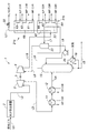
図5は、本発明の第1実施形態の第2変形例に係る天然ガスの液化システムにおける液化処理の流れを示す構成図である。表4には、第2変形例の液化システムにおける原料ガスの温度、圧力、流量、及び各成分のモル分率等の一例が示されている。また、表5には、液化システムで用いられる混合冷媒系の冷凍サイクルにおける冷媒の温度、圧力、流量、及び各成分のモル分率等の一例が示されている。なお、図5に示す液化システム1では、第1実施形態(他の変形例を含む)に係る液化システム1と同様の構成要素についてはそれぞれ同一の符号を付し、以下で言及する事項を除いて詳細な説明を省略する。
( Second modification of the first embodiment)
FIG. 5 is a configuration diagram showing the flow of the liquefaction process in the natural gas liquefaction system according to the second modification of the first embodiment of the present invention. Table 4 shows an example of the temperature, pressure, flow rate, and mole fraction of each component of the raw material gas in the liquefaction system of the second modified example. Table 5 shows an example of the refrigerant temperature, pressure, flow rate, molar fraction of each component, and the like in the mixed refrigerant refrigeration cycle used in the liquefaction system. In addition, in the liquefaction system 1 shown in FIG. 5 , the same code | symbol is attached | subjected about the component similar to the liquefaction system 1 which concerns on 1st Embodiment (another modification is included), respectively, and the matter mentioned below is remove | excluded. Detailed description is omitted.
図5に示すように、第2変形例による液化システム1では、ラインL10は、液化装置21内の中間領域Z2に配置された管回路31に接続されている。また、図5には、液化システム1が備える混合冷媒方式の冷凍サイクルシステム70の構成が示されている。ここでは、原料ガスとして表4に示すような重質分(高級炭化水素含有量)の比較的多い天然ガス(リッチガス)が用いられる。蒸留装置15の塔頂留出物は、第1膨張機3での原料ガスの膨張を調整することにより、上述の第1実施形態の場合に比べてより低圧(約3,300kPaA)とされる。これにより、第1実施形態のようなリーンガスの液化処理の場合と比べて、蒸留装置15の塔底のラインL5を介した天然ガス液(Natural Gas Liquid)の回収を高い効率(例えば、プロパンを約89%、ブタンを約100%回収)で実施可能となる。
As shown in FIG. 5 , in the liquefaction system 1 according to the second modification, the line L < b > 10 is connected to a
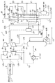
(第1実施形態の第3変形例)
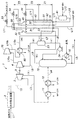
図6は、本発明の第1実施形態の第3変形例に係る天然ガスの液化システムにおける液化処理の流れを示す構成図である。表1には、第3変形例の液化システムにおける原料ガスの温度、圧力、流量、及び各成分のモル分率等の一例が示されている。なお、図6に示す液化システム1では、第1実施形態(他の変形例を含む)に係る液化システム1と同様の構成要素についてはそれぞれ同一の符号を付し、以下で言及する事項を除いて詳細な説明を省略する。
( Third Modification of First Embodiment)
FIG. 6 is a configuration diagram showing the flow of the liquefaction process in the natural gas liquefaction system according to the third modification of the first embodiment of the present invention. Table 1 shows an example of the temperature, pressure, flow rate, and mole fraction of each component in the liquefaction system of the third modification. In addition, in the liquefaction system 1 shown in FIG. 6 , about the component similar to the liquefaction system 1 which concerns on 1st Embodiment (another modification is included), respectively, the same code | symbol is attached | subjected and the matter mentioned below is remove | excluded. Detailed description is omitted.
この第3変形例では、上述の第2変形例と同様に原料ガスとしてリッチガスが用いられ、特に、原料ガスの組成によってその臨界圧力が比較的高くなる場合に好適な構成を示している。液化システム1では、蒸留装置15と第1気液分離槽23との間のラインL6に低圧(LP)のプロパン冷媒(C3R)を用いる第3冷却器86が設けられ、第1圧縮機4と液化装置21との間のラインL10に同様に低圧のプロパン冷媒を用いる第2冷却器85が設けられている。このような構成により、蒸留装置15からのラインL6を流れる原料ガスは、第3冷却器86によって冷却された後に第1気液分離槽23に導入される。つまり、第3変形例では、上述の第2変形例等のように第1気液分離槽23に導入する原料ガスを液化装置21(管回路22)で冷却する必要はなく、液化装置21の液化処理の負荷を軽減できるという利点がある。
In the third modified example, a rich gas is used as the source gas as in the second modified example described above, and in particular, a configuration suitable for a case where the critical pressure becomes relatively high depending on the composition of the source gas is shown. In the liquefaction system 1, a
また、第1圧縮機4からのラインL10を流れる原料ガスは、第2冷却器85によって冷却された後に液化装置21に導入される。この場合、ラインL10の下流側は、液化装置21において最も温度の高い暖温領域Z1に配置された管回路30に接続されている。つまり、第3変形例では、第1圧縮機4による原料ガスの昇圧によって原料ガスの温度レベルが適切なレベルを超えた場合でも、第2冷却器85での冷却によって原料ガスの温度を液化装置21の暖温領域Z1の温度レベルに近づけ、その結果、液化装置21の熱的負荷を軽減(熱応力の発生等を抑制)することができるという利点がある。
In addition, the raw material gas flowing through the line L <b> 10 from the
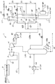
(第2実施形態)
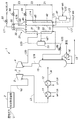
図7は本発明の第2実施形態に係る天然ガスの液化システムにおける液化処理の流れを示す構成図である。また、表2には、第2実施形態に係る液化システム1における原料ガスの温度、圧力、流量、及び各成分のモル分率等の一例を示す。なお、図7に示す液化システム1では、第1実施形態に係る液化システム1と同様の構成要素についてはそれぞれ同一の符号を付し、以下で言及する事項を除いて詳細な説明を省略する。
(Second Embodiment)
FIG. 7 is a configuration diagram showing the flow of liquefaction processing in the natural gas liquefaction system according to the second embodiment of the present invention. Table 2 shows an example of the temperature, pressure, flow rate, and mole fraction of each component of the raw material gas in the liquefaction system 1 according to the second embodiment. In addition, in the liquefaction system 1 shown in FIG. 7 , the same code | symbol is attached | subjected about the component similar to the liquefaction system 1 which concerns on 1st Embodiment, respectively, and detailed description is abbreviate | omitted except the matter mentioned below.
このように、第2実施形態の液化システム1では、液化装置21に導入される原料ガスの温度が増大した場合でも、原料ガスをより温度レベルの近い液化装置21の暖温領域Z1(高温側)に導入する構成としたため、液化装置21の熱的負荷を軽減(熱応力の発生等を抑制)すると共に、液化処理の効率を高めることができる。なお、原料ガスを液化装置21の暖温領域Z1に導入する構成は、ガス供給用の第4圧縮機71の有無に拘わらず、原料ガスの圧力レベルに応じて適宜採用することができる。また、原料ガスの圧力が高すぎて、原料ガスの温度が液化装置21の暖温領域Z1(高温側)の温度よりも高くなる場合は、図6と同様に、第2冷却器85を設置して液化装置21の負荷を軽減することができる。
As described above, in the liquefaction system 1 of the second embodiment, even when the temperature of the raw material gas introduced into the
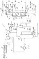
(第3実施形態)
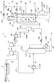
図8は本発明の第3実施形態に係る天然ガスの液化システムにおける液化処理の流れを示す構成図である。また、表3には、第3実施形態に係る液化システム1における原料ガスの温度、圧力、流量、及び各成分のモル分率等の一例を示す。なお、図8に示す液化システム1では、第1及び第2実施形態に係る液化システム1と同様の構成要素についてはそれぞれ同一の符号を付し、以下で言及する事項を除いて詳細な説明を省略する。
(Third embodiment)
FIG. 8 is a configuration diagram showing the flow of liquefaction processing in the natural gas liquefaction system according to the third embodiment of the present invention. Table 3 shows an example of the temperature, pressure, flow rate, and mole fraction of each component of the raw material gas in the liquefaction system 1 according to the third embodiment. In addition, in the liquefaction system 1 shown in FIG. 8 , about the component similar to the liquefaction system 1 which concerns on 1st and 2nd embodiment, respectively, the same code | symbol is attached | subjected, and detailed description except the matter mentioned below is carried out. Omitted.
(第3実施形態の変形例)
図9は本発明の第3実施形態の変形例に係る天然ガスの液化システムにおける液化処理の流れを示す構成図である。なお、図9に示す液化システム1では、第1から第3実施形態に係る液化システム1と同様の構成要素についてはそれぞれ同一の符号を付し、以下で言及する事項を除いて詳細な説明を省略する。
(Modification of the third embodiment)
FIG. 9 is a configuration diagram showing the flow of liquefaction processing in a natural gas liquefaction system according to a modification of the third embodiment of the present invention. In addition, in the liquefaction system 1 shown in FIG. 9 , the same code | symbol is attached | subjected about the component similar to the liquefaction system 1 which concerns on 1st to 3rd embodiment, respectively, and detailed description is excluded except the matter mentioned below. Omitted.
(第4実施形態)
図10は本発明の第4実施形態に係る天然ガスの液化システムにおける液化処理の流れを示す構成図である。また、表4には、第4実施形態に係る液化システム1における原料ガスの温度、圧力、流量、及び各成分のモル分率等の一例を示す。なお、図10に示す液化システム1では、第1から第3実施形態に係る液化システム1と同様の構成要素についてはそれぞれ同一の符号を付し、以下で言及する事項を除いて詳細な説明を省略する。
(Fourth embodiment)
FIG. 10: is a block diagram which shows the flow of the liquefaction process in the liquefaction system of the natural gas which concerns on 4th Embodiment of this invention. Table 4 shows an example of the temperature, pressure, flow rate, and mole fraction of each component of the raw material gas in the liquefaction system 1 according to the fourth embodiment. In addition, in the liquefaction system 1 shown in FIG. 10 , the same code | symbol is attached | subjected about the component similar to the liquefaction system 1 which concerns on 1st to 3rd embodiment, respectively, and detailed description is excluded except the matter mentioned below. Omitted.
第4実施形態の液化システム1では、図8の第3実施形態に示した第2圧縮機75の下流に、低圧(LP)のプロパン冷媒(C3R)を用いる更なる第2冷却器85が設けられている。第1圧縮機4からラインL10aに送出された原料ガスは、第2圧縮機75において昇圧された後にラインL10bを介して第2冷却器85に送られ、そこで更に冷却された後、ラインL10cを介して液化装置21に導入される。液化装置21の内部は、第3実施形態と同様の構成を有しており、ラインL10cは、液化装置21内の暖温領域Z1に配置された管回路30に接続されている。
In liquefaction system 1 of the fourth embodiment, third downstream of the
(第5実施形態)
図11は本発明の第5実施形態に係る天然ガスの液化システムにおける液化処理の流れを示す構成図である。なお、図11に示す液化システム1では、第1から第4実施形態に係る液化システム1と同様の構成要素についてはそれぞれ同一の符号を付し、以下で言及する事項を除いて詳細な説明を省略する。
(Fifth embodiment)
FIG. 11: is a block diagram which shows the flow of the liquefaction process in the liquefaction system of the natural gas which concerns on 5th Embodiment of this invention. In addition, in the liquefaction system 1 shown in FIG. 11 , the same code | symbol is attached | subjected about the component similar to the liquefaction system 1 which concerns on 1st to 4th embodiment, respectively, and detailed description except the matter mentioned below is carried out. Omitted.
図12は本発明の第6実施形態に係る天然ガスの液化システムにおける液化処理の流れを示す構成図である。なお、図12に示す液化システム1では、第1から第5実施形態に係る液化システム1と同様の構成要素についてはそれぞれ同一の符号を付し、以下で言及する事項を除いて詳細な説明を省略する。
FIG. 12: is a block diagram which shows the flow of the liquefaction process in the liquefaction system of the natural gas which concerns on 6th Embodiment of this invention. In addition, in the liquefaction system 1 shown in FIG. 12 , the same code | symbol is attached | subjected about the component similar to the liquefaction system 1 which concerns on 1st to 5th embodiment, respectively, and detailed description is excluded except the matter mentioned below. Omitted.
(第6実施形態の第1変形例)
図13は本発明の第6実施形態の変形例に係る天然ガスの液化システムにおける液化処理の流れを示す構成図である。また、表5には、第6実施形態の変形例に係る液化システム1における原料ガスの温度、圧力、流量、及び各成分のモル分率等の一例を示す。なお、図13に示す液化システム1では、第6実施形態に係る液化システム1と同様の構成要素についてはそれぞれ同一の符号を付し、以下で言及する事項を除いて詳細な説明を省略する。
(First Modification of Sixth Embodiment)
FIG. 13: is a block diagram which shows the flow of the liquefaction process in the liquefaction system of the natural gas which concerns on the modification of 6th Embodiment of this invention. Table 5 shows an example of the temperature, pressure, flow rate, and mole fraction of each component in the liquefaction system 1 according to the modification of the sixth embodiment. In addition, in the liquefaction system 1 shown in FIG. 13 , the same code | symbol is attached | subjected about the component similar to the liquefaction system 1 which concerns on 6th Embodiment, respectively, and detailed description is abbreviate | omitted except the matter mentioned below.
この変形例による液化システム1では、図12の第6実施形態に示した第1冷却器11が省略される一方、第1圧縮機4の下流に、低圧のプロパンを冷媒として用いる更なる第2冷却器85が設けられている。原料ガスは、第1圧縮機4からラインL20aを介して第2冷却器85に送られて冷却された後、ラインL20bを介して液化装置21の暖温領域Z1に配置された管回路22に送られて更に冷却され、その後、ラインL21を介して第1気液分離槽23に導入される。
In the liquefaction system 1 according to this modified example, the
(第6実施形態の第2変形例)
図14は、本発明の第6実施形態の第2変形例に係る天然ガスの液化システムにおける液化処理の流れを示す構成図である。表6には、第2変形例の液化システムにおける原料ガスの温度、圧力、流量、及び各成分のモル分率等の一例が示されている。なお、図14に示す液化システム1では、第6実施形態(他の変形例を含む)に係る液化システム1と同様の構成要素についてはそれぞれ同一の符号を付し、以下で言及する事項を除いて詳細な説明を省略する。
( Second Modification of Sixth Embodiment)
FIG. 14: is a block diagram which shows the flow of the liquefaction process in the liquefaction system of the natural gas which concerns on the 2nd modification of 6th Embodiment of this invention. Table 6 shows an example of the temperature, pressure, flow rate, and mole fraction of each component of the raw material gas in the liquefaction system of the second modification. In addition, in the liquefaction system 1 shown in FIG. 14 , the same code | symbol is attached | subjected about the component similar to the liquefaction system 1 which concerns on 6th Embodiment (another modification is included), respectively, and the matter mentioned below is remove | excluded. Detailed description is omitted.
この第2変形例では、原料ガスとして上述の第6実施形態よりも低圧のガスが用いられ、特に、窒素や重質分を含む原料ガスの組成によってその臨界圧力が比較的高くなる場合に好適な構成を示している。液化システム1では、第6実施形態の第1変形例と同様に、原料ガスは、第1圧縮機4からラインL20aを介して第2冷却器85に送られて冷却された後、ラインL20bを介して第1気液分離槽23に導入される。一方、第2変形例では、ラインL20bは、液化装置21を介さずに第1気液分離槽23に接続され、この第1気液分離槽23において気相成分を構成する原料ガスは、ラインL23を介して液化装置21内において最も温度の高い暖温領域Z1に配置された管回路30に送られる。このような構成により、第2変形例では、上述の第1変形例のように第1気液分離槽23に導入する原料ガスを液化装置21で冷却(管回路22に導入)する必要はなく、液化装置21の液化処理の負荷を軽減できるという利点がある。
In this second modification, a gas having a lower pressure than that of the above-described sixth embodiment is used as the source gas, and particularly suitable when the critical pressure is relatively high due to the composition of the source gas containing nitrogen and heavy components. The structure is shown. In the liquefaction system 1, as in the first modification of the sixth embodiment, the raw material gas is sent from the
(第7実施形態)
図15は本発明の第7実施形態に係る天然ガスの液化システムにおける液化処理の流れを示す構成図である。なお、図15に示す液化システム1では、第1から第6実施形態に係る液化システム1と同様の構成要素についてはそれぞれ同一の符号を付し、以下で言及する事項を除いて詳細な説明を省略する。
(Seventh embodiment)
FIG. 15: is a block diagram which shows the flow of the liquefaction process in the liquefaction system of the natural gas which concerns on 7th Embodiment of this invention. In addition, in the liquefaction system 1 shown in FIG. 15 , the same code | symbol is attached | subjected about the component similar to the liquefaction system 1 which concerns on 1st to 6th embodiment, respectively, and detailed description is excluded except the matter mentioned below. Omitted.
図15において、水分除去装置2からの原料ガスは、それぞれラインL2a、L2bを介して第1及び第2膨張機3a、3bに送られる。第1及び第2膨張機3a、3bからの原料ガスは、ラインL3a、L3b、L3を介して冷却器12に送られる。この場合、上述のような冷却器群に必要とされる冷却能が低減されるため、低圧(LP)のプロパン冷媒(C3R)を用いる1台の冷却器12のみが設置されている。
In FIG. 15 , the raw material gas from the
図16は本発明の第8実施形態に係る天然ガスの液化システムにおける液化処理の流れを示す構成図である。なお、図16に示す液化システム1では、第1から第7実施形態に係る液化システム1と同様の構成要素についてはそれぞれ同一の符号を付し、以下で言及する事項を除いて詳細な説明を省略する。
FIG. 16: is a block diagram which shows the flow of the liquefaction process in the liquefaction system of the natural gas which concerns on 8th Embodiment of this invention. In addition, in the liquefaction system 1 shown in FIG. 16 , about the component similar to the liquefaction system 1 which concerns on 1st-7th embodiment, respectively, the same code | symbol is attached | subjected, and detailed description is excluded except the matter mentioned below. Omitted.
図16において、水分除去装置2からの原料ガスは、ラインL2を介して第1膨張機3aに送られ、そこで膨張した後、ラインL3を介してセパレータ91に導入される。セパレータ91において、気相成分として分離された原料ガスは、ラインL1を介して第2膨張機3bに送られ、そこで膨張した後、ラインL2を介して冷却器12に送られる。一方、セパレータ91は、原料ガス中の液相成分(凝縮成分)を分離し、その液相成分を構成する液体は、ラインL3に設けられた膨張弁92を介して冷却器12に送られる。
In FIG. 16 , the raw material gas from the
(第9実施形態)
図17は本発明の第9実施形態に係る天然ガスの液化システムにおける液化処理の流れを示す構成図である。なお、図17に示す液化システム1では、第1から第8実施形態に係る液化システム1と同様の構成要素についてはそれぞれ同一の符号を付し、以下で言及する事項を除いて詳細な説明を省略する。
(Ninth embodiment)
FIG. 17: is a block diagram which shows the flow of the liquefaction process in the liquefaction system of the natural gas which concerns on 9th Embodiment of this invention. In addition, in the liquefaction system 1 shown in FIG. 17 , the same code | symbol is attached | subjected about the component similar to the liquefaction system 1 which concerns on 1st to 8th embodiment, respectively, and detailed description is excluded except the matter mentioned below. Omitted.
(第9実施形態の変形例)
図18は本発明の第9実施形態の変形例に係る天然ガスの液化システムにおける液化処理の流れを示す構成図である。なお、図18に示す液化システム1では、第9実施形態に係る液化システム1と同様の構成要素についてはそれぞれ同一の符号を付し、以下で言及する事項を除いて詳細な説明を省略する。
(Modification of the ninth embodiment)
FIG. 18: is a block diagram which shows the flow of the liquefaction process in the liquefaction system of the natural gas which concerns on the modification of 9th Embodiment of this invention. In addition, in the liquefaction system 1 shown in FIG. 18 , the same code | symbol is attached | subjected about the component similar to the liquefaction system 1 which concerns on 9th Embodiment, respectively, and detailed description is abbreviate | omitted except the matter mentioned below.
(第10実施形態)
図19は本発明の第10実施形態に係る天然ガスの液化システムにおける液化処理の流れを示す構成図である。なお、図19に示す液化システム1では、第1から第9実施形態に係る液化システム1と同様の構成要素についてはそれぞれ同一の符号を付し、以下で言及する事項を除いて詳細な説明を省略する。
(10th Embodiment)
FIG. 19 is a configuration diagram showing the flow of liquefaction processing in the natural gas liquefaction system according to the tenth embodiment of the present invention. In addition, in the liquefaction system 1 shown in FIG. 19 , the same code | symbol is attached | subjected about the component similar to the liquefaction system 1 which concerns on 1st to 9th embodiment, respectively, and detailed description is excluded except the matter mentioned below. Omitted.
この第10実施形態による液化システム1では、上述の図12に示した第6実施形態と類似の構成を有するが、蒸留装置15の上流側の構成において、図3に示した参考例と類似の構成が採用されている。より詳細には、第10実施形態による液化システム1では、膨張機3は、冷却器群(ここでは、3台の冷却器10、11、12)の下流側に配置され、冷却器12から送出された原料ガスは、ラインL4aを介してセパレータ13に送られて気液分離される。セパレータ13において気相成分を構成する原料ガスは、ラインL4bを介して膨張機3に送られ、膨張機3で膨張した後、ラインL4cを介して蒸留装置15に送られる。一方、セパレータ13において液相成分を構成する原料ガスは、膨張弁14が設けられたラインL4dに送出される。その液相成分は、膨張弁14で膨張した後、膨張機3からの原料ガスと共にラインL4cを介して蒸留装置15に送られる。
The liquefaction system 1 according to the tenth embodiment has a configuration similar to that of the sixth embodiment shown in FIG. 12 described above, but is similar to the reference example shown in FIG. 3 in the configuration on the upstream side of the
(第11実施形態)
図20は本発明の第11実施形態に係る天然ガスの液化システムにおける液化処理の流れを示す構成図である。なお、図20に示す液化システム1では、第1から第10実施形態に係る液化システム1と同様の構成要素についてはそれぞれ同一の符号を付し、以下で言及する事項を除いて詳細な説明を省略する。
(Eleventh embodiment)
FIG. 20 is a configuration diagram showing the flow of liquefaction processing in the natural gas liquefaction system according to the eleventh embodiment of the present invention. In addition, in the liquefaction system 1 shown in FIG. 20 , the same code | symbol is attached | subjected about the component similar to the liquefaction system 1 which concerns on 1st to 10th embodiment, respectively, and detailed description is excluded except the matter mentioned below. Omitted.
この第11実施形態による液化システム1では、上述の第6実施形態と類似の構成を有するが、第1膨張機3及び第1圧縮機4の接続関係については、図11に示した第5実施形態と同様の構成が採用されている。より詳細には、第11実施形態による液化システム1では、第1膨張機3及び第1圧縮機4は機械的に接続されておらず、両者は電気的に接続されている。第1膨張機3には発電装置87が接続されており、この発電装置87により、第1膨張機3が発生する動力は電力に変換される。この発電装置87で発生した電力は、第1圧縮機4を駆動するモータ84に供給される(すなわち、第1膨張機3において発生した動力を第1圧縮機4で利用する)。なお、発電装置87から供給される電力は、モータ84を駆動する電力の少なくとも一部であればよく、電力が不足した場合には、図示しない外部の電力供給源から別途電力が供給される。
In liquefaction system 1 according to the eleventh embodiment has a structure similar to the sixth embodiment described above, for the connection of the
(膨張機及び圧縮機の接続構造の変形例)
図21及び図22は、それぞれ上述の各実施形態における膨張機と圧縮機との機械的接続構造の第1及び第2変形例を示す図である。
(Modification of connection structure of expander and compressor)
FIGS. 21 and 22 are views showing first and second modifications of the mechanical connection structure between the expander and the compressor in each of the above-described embodiments, respectively.
図21に示す例では、第1膨張機3と第1圧縮機4との間にモータ(第2モータ)84が介装され、モータ84の速度は可変周波数駆動を行うコントローラ82によって制御される。モータ84には外部から電力が供給される。ここで、第1膨張機3、第1圧縮機4、及びモータ84は、同軸上に設けられており、第1膨張機3で発生した膨張に基づく動力を第1圧縮機4の動力として利用することができる。これによりモータ84の動力を低減することが可能となる。このように、第1膨張機3で発生した動力を補うようにモータ84の動力を利用することで、第1圧縮機4の吐出圧を安定的に増大させることが可能となる。
In the example shown in FIG. 21 , a motor (second motor) 84 is interposed between the
一方、図22に示す例では、第1膨張機3、第1圧縮機4、及びモータ(第2モータ)84の回転軸には、それぞれギヤ96、97、98が取り付けられている。第1膨張機3のギヤ96は、モータ84のギヤ97と噛合し、更に、モータ84のギヤ97は、第1圧縮機4のギヤ98と噛合する。これにより、第1膨張機3及び第1圧縮機4は、モータ84を介して互いに動力を伝達可能に接続されている。このような構造により、第1膨張機3で発生した動力を補うようにモータ84の動力を利用することで、第1圧縮機4の吐出圧を安定的に増大させることが可能となる。なお、第1膨張機3、第1圧縮機4、及びモータ84の接続については、遊星歯車機構など周知の歯車機構を適用することができる。
On the other hand, in the example shown in FIG. 22 , gears 96, 97, and 98 are attached to the rotation shafts of the
1 液化システム
2 水分除去装置
3、3a 第1膨張機
3b 第2膨張機
4、4a 第1圧縮機
4b 第3圧縮機
5 シャフト
10、11、12 第1冷却器
15 蒸留装置
21 液化装置
23 第1気液分離槽
33 膨張弁
41 冷媒セパレータ
44 膨張弁
45 スプレーヘッダ
54 膨張弁
55 スプレーヘッダ
71 第4圧縮機
72 第4冷却器
75 第2圧縮機
81 モータ(第1モータ)
82 コントローラ
83 圧力計
84 モータ(第2モータ)
85 第2冷却器
86 第3冷却器
87 発電装置
89 膨張弁
91 セパレータ
92 膨張弁
96 ギヤ
97 ギヤ
98 ギヤ
Z1 暖温領域
Z2 中間領域
Z3 冷温領域
DESCRIPTION OF SYMBOLS 1
82
85 Second cooler 86 Third cooler 87
Claims (19)
供給源から加圧状態で得られた天然ガスが冷却および加熱されることなく原料ガスとして供給され、当該原料ガスを膨張させることによって動力を発生させる第1膨張機と、
前記第1膨張機における膨張によって減圧された前記原料ガスを、前記原料ガスとは異なる外部の冷媒のみを用いて冷却する第1冷却器と、
前記第1冷却器によって冷却された前記原料ガスを蒸留することにより、前記原料ガス中の重質分を低減または除去する蒸留装置と、
前記第1膨張機において発生した動力を利用することにより、前記蒸留装置において前記重質分が低減または除去された前記原料ガスを圧縮する第1圧縮機と、
前記第1圧縮機によって圧縮された前記原料ガスを冷媒との熱交換によって液化する液化装置と
を備えたことを特徴とする天然ガスの液化システム。 A natural gas liquefaction system that cools natural gas to produce liquefied natural gas,
A first expander that supplies natural gas obtained in a pressurized state from a supply source as raw material gas without being cooled and heated, and generates power by expanding the raw material gas ;
A first cooler that cools the raw material gas decompressed by expansion in the first expander using only an external refrigerant different from the raw material gas ;
A distillation apparatus for reducing or removing heavy components in the raw material gas by distilling the raw material gas cooled by the first cooler;
A first compressor that compresses the raw material gas from which the heavy component has been reduced or removed in the distillation apparatus by utilizing power generated in the first expander;
A natural gas liquefaction system comprising: a liquefaction device that liquefies the raw material gas compressed by the first compressor by heat exchange with a refrigerant.
前記第1圧縮機から送出された前記原料ガスは、前記スプール巻き型熱交換器に対し、当該スプール巻き型熱交換器内の高温側に位置する暖温領域に導入されることを特徴とする請求項1または請求項2に記載の天然ガスの液化システム。 The liquefaction device comprises a spool-winding heat exchanger,
The raw material gas delivered from the first compressor is introduced into a warm temperature region located on a high temperature side in the spool-winding heat exchanger with respect to the spool-winding heat exchanger. The natural gas liquefaction system according to claim 1 or 2.
前記第2圧縮機は、前記第1モータによって駆動されることを特徴とする請求項4に記載の天然ガスの液化システム。 A first motor that is driven by electric power from the outside and that is driven and controlled based on the pressure value of the source gas introduced into the liquefaction device;
5. The natural gas liquefaction system according to claim 4, wherein the second compressor is driven by the first motor.
前記第1圧縮機を駆動する第2モータと
を更に備え、
前記第2モータは、前記発電装置からの電力を利用して駆動されることを特徴とする請求項1に記載の天然ガスの液化システム。 A power generation device that converts power generated in the first expander into electric power;
A second motor for driving the first compressor;
2. The natural gas liquefaction system according to claim 1, wherein the second motor is driven using electric power from the power generation device.
前記第1圧縮機は、前記第1膨張機において発生した動力と、前記第2モータの動力とを利用することにより、前記原料ガスを圧縮することを特徴とする請求項1に記載の天然ガスの液化システム。 A second motor that mechanically connects the first expander and the first compressor and receives an external power supply;
The natural gas according to claim 1, wherein the first compressor compresses the raw material gas by using power generated in the first expander and power of the second motor. Liquefaction system.
前記第1圧縮機において圧縮された前記原料ガスが前記液化装置を介して導入される第1気液分離槽を備え、
前記第1気液分離槽において分離された前記原料ガスの気相成分は、前記液化装置に再び導入される一方、前記原料ガスの液相成分は、前記蒸留装置に環流されることを特徴とする請求項1に記載の天然ガスの液化システム。 The first compressor is directly introduced with the raw material gas from which the heavy component has been reduced or removed in the distillation apparatus,
A first gas-liquid separation tank into which the source gas compressed in the first compressor is introduced via the liquefaction device;
The gas phase component of the source gas separated in the first gas-liquid separation tank is reintroduced into the liquefaction device, while the liquid phase component of the source gas is circulated to the distillation device. The natural gas liquefaction system according to claim 1.
前記蒸留装置と前記第1圧縮機との間に配置され、第2膨張機において発生した動力を利用することにより、前記蒸留装置によって蒸留された前記原料ガスを圧縮する第3圧縮機と
を更に備えたことを特徴とする請求項1に記載の天然ガスの液化システム。 A second expander that is disposed between the first expander and the distillation device and generates power by expanding the source gas;
A third compressor that is disposed between the distillation apparatus and the first compressor and that compresses the raw material gas distilled by the distillation apparatus by using power generated in the second expander; The natural gas liquefaction system according to claim 1, further comprising:
前記蒸留装置と前記第1圧縮機との間に配置され、第2膨張機において発生した動力を利用することにより、前記蒸留装置によって蒸留された前記原料ガスを圧縮する第3圧縮機と
を更に備えたことを特徴とする請求項1に記載の天然ガスの液化システム。 A second expander that is arranged in parallel with the first expander and generates power by expanding the source gas;
A third compressor that is disposed between the distillation apparatus and the first compressor and that compresses the raw material gas distilled by the distillation apparatus by using power generated in the second expander; The natural gas liquefaction system according to claim 1, further comprising:
前記蒸留装置と前記第1気液分離槽との間に配置され、前記蒸留装置からの前記塔頂留出物を冷却する第3冷却器とを更に備え、
前記第1圧縮機は、前記第1気液分離槽において分離された前記原料ガスの気相成分を圧縮することを特徴とする請求項1から請求項8のいずれかに記載の天然ガスの液化システム A first gas-liquid separation tank into which the top distillate from the distillation apparatus is introduced;
A third cooler that is disposed between the distillation apparatus and the first gas-liquid separation tank and cools the overhead distillate from the distillation apparatus ;
The natural gas liquefaction according to any one of claims 1 to 8, wherein the first compressor compresses a gas phase component of the source gas separated in the first gas-liquid separation tank. system
供給源から加圧状態で得られた天然ガスが冷却および加熱されることなく原料ガスとして供給され、当該原料ガスを膨張させることによって動力を発生させる第1膨張工程と、
前記第1膨張工程における膨張によって減圧された前記原料ガスを、前記原料ガスとは異なる外部の冷媒のみを用いて冷却する第1冷却工程と、
前記第1冷却工程によって冷却された前記原料ガスを蒸留することにより、前記原料ガス中の重質分を低減または除去する蒸留工程と、
前記第1膨張工程において発生した動力を利用することにより、前記蒸留工程において前記重質分が低減または除去された前記原料ガスを圧縮する第1圧縮工程と、
前記第1圧縮工程によって圧縮された前記原料ガスを冷媒との熱交換によって液化する液化工程と
を備えたことを特徴とする天然ガスの液化方法。 A natural gas liquefaction method for cooling natural gas to produce liquefied natural gas,
A first expansion step in which natural gas obtained in a pressurized state from a supply source is supplied as a raw material gas without being cooled and heated, and power is generated by expanding the raw material gas ;
A first cooling step of cooling the source gas decompressed by the expansion in the first expansion step using only an external refrigerant different from the source gas ;
A distillation step of reducing or removing heavy components in the raw material gas by distilling the raw material gas cooled in the first cooling step;
A first compression step of compressing the raw material gas from which the heavy component has been reduced or removed in the distillation step by utilizing the power generated in the first expansion step;
A natural gas liquefaction method comprising: a liquefaction step of liquefying the raw material gas compressed in the first compression step by heat exchange with a refrigerant.
Priority Applications (30)
| Application Number | Priority Date | Filing Date | Title |
|---|---|---|---|
| JP2014050786A JP6225049B2 (en) | 2013-12-26 | 2014-03-13 | Natural gas liquefaction system and method |
| US15/104,564 US20160313056A1 (en) | 2013-12-26 | 2014-12-26 | System and method for liquefaction of natural gas |
| ES14873799T ES2838498T3 (en) | 2013-12-26 | 2014-12-26 | Natural gas liquefaction system and liquefaction method |
| PCT/JP2014/006502 WO2015098125A1 (en) | 2013-12-26 | 2014-12-26 | Natural gas liquefying system and liquefying method |
| RU2016130315A RU2016130315A (en) | 2013-12-26 | 2014-12-26 | SYSTEM AND METHOD FOR LIQUIDING NATURAL GAS |
| AP2016009511A AP2016009511A0 (en) | 2013-12-26 | 2014-12-26 | System and method for liquefaction of natural gas |
| CA3029950A CA3029950C (en) | 2013-12-26 | 2014-12-26 | System and method for liquefaction of natural gas |
| CA2934435A CA2934435A1 (en) | 2013-12-26 | 2014-12-26 | System and method for liquefaction of natural gas |
| EP16201992.1A EP3168558B1 (en) | 2013-12-26 | 2014-12-26 | System and method for liquefaction of natural gas |
| CA2934895A CA2934895C (en) | 2013-12-26 | 2014-12-26 | System and method for liquefaction of natural gas |
| RU2016144151A RU2668303C1 (en) | 2013-12-26 | 2014-12-26 | System and method for liquefying of natural gas (options) |
| AU2014371866A AU2014371866B9 (en) | 2013-12-26 | 2014-12-26 | System and method for liquefaction of natural gas |
| US15/108,042 US20170160008A9 (en) | 2013-12-26 | 2014-12-26 | System and method for liquefaction of natural gas |
| EP14873799.2A EP3091319B1 (en) | 2013-12-26 | 2014-12-26 | Natural gas liquefying system and liquefying method |
| AP2016009308A AP2016009308A0 (en) | 2013-12-26 | 2014-12-26 | System and method for liquefaction of natural gas |
| CN201480071324.2A CN106062495B (en) | 2013-12-26 | 2014-12-26 | Natural gas liquefaction system and method |
| PE2016002091A PE20170506A1 (en) | 2013-12-26 | 2014-12-26 | NATURAL GAS LIQUEFACTION SYSTEM AND METHOD |
| KR1020167030036A KR101894076B1 (en) | 2013-12-26 | 2014-12-26 | Natural gas liquefying system and liquefying method |
| CN201611162705.9A CN107339853B (en) | 2013-12-26 | 2014-12-26 | Natural gas liquefaction system and method |
| MYPI2016702301A MY176671A (en) | 2013-12-26 | 2014-12-26 | System and method for liquefaction of natural gas |
| KR1020167020287A KR101840721B1 (en) | 2013-12-26 | 2014-12-26 | Natural gas liquefying system and liquefying method |
| AU2014371867A AU2014371867A1 (en) | 2013-12-26 | 2014-12-26 | System and method for liquefaction of natural gas |
| AP2016009309A AP2016009309A0 (en) | 2013-12-26 | 2014-12-26 | System and method for liquefaction of natural gas |
| RU2016130314A RU2651007C2 (en) | 2013-12-26 | 2014-12-26 | System and method for the natural gas liquefaction |
| PE2016000954A PE20161119A1 (en) | 2013-12-26 | 2014-12-26 | NATURAL GAS LIQUEFACTION SYSTEM AND METHOD |
| PCT/JP2014/006501 WO2015098124A1 (en) | 2013-12-26 | 2014-12-26 | Natural gas liquefying system and liquefying method |
| SA516371407A SA516371407B1 (en) | 2013-12-26 | 2016-06-24 | System and Method for Liquefaction of Natural Gas |
| SA516380183A SA516380183B1 (en) | 2013-12-26 | 2016-06-24 | System and Method for Liquefaction of Natural Gas |
| US15/293,485 US20170030633A1 (en) | 2013-12-26 | 2016-10-14 | System and method for liquefacation of natural gas |
| AU2016250325A AU2016250325B2 (en) | 2013-12-26 | 2016-10-24 | System and method for liquefaction of natural gas |
Applications Claiming Priority (3)
| Application Number | Priority Date | Filing Date | Title |
|---|---|---|---|
| JP2013270011 | 2013-12-26 | ||
| JP2013270011 | 2013-12-26 | ||
| JP2014050786A JP6225049B2 (en) | 2013-12-26 | 2014-03-13 | Natural gas liquefaction system and method |
Related Child Applications (1)
| Application Number | Title | Priority Date | Filing Date |
|---|---|---|---|
| JP2017014126A Division JP6517251B2 (en) | 2013-12-26 | 2017-01-30 | Natural gas liquefaction system and liquefaction method |
Publications (3)
| Publication Number | Publication Date |
|---|---|
| JP2015143600A JP2015143600A (en) | 2015-08-06 |
| JP2015143600A5 true JP2015143600A5 (en) | 2017-04-13 |
| JP6225049B2 JP6225049B2 (en) | 2017-11-01 |
Family
ID=53478019
Family Applications (1)
| Application Number | Title | Priority Date | Filing Date |
|---|---|---|---|
| JP2014050786A Active JP6225049B2 (en) | 2013-12-26 | 2014-03-13 | Natural gas liquefaction system and method |
Country Status (14)
| Country | Link |
|---|---|
| US (3) | US20170160008A9 (en) |
| EP (2) | EP3091319B1 (en) |
| JP (1) | JP6225049B2 (en) |
| KR (2) | KR101894076B1 (en) |
| CN (2) | CN106062495B (en) |
| AP (3) | AP2016009511A0 (en) |
| AU (3) | AU2014371867A1 (en) |
| CA (3) | CA2934895C (en) |
| ES (1) | ES2838498T3 (en) |
| MY (1) | MY176671A (en) |
| PE (2) | PE20170506A1 (en) |
| RU (3) | RU2651007C2 (en) |
| SA (2) | SA516371407B1 (en) |
| WO (2) | WO2015098124A1 (en) |
Families Citing this family (19)
| Publication number | Priority date | Publication date | Assignee | Title |
|---|---|---|---|---|
| JP6517251B2 (en) * | 2013-12-26 | 2019-05-22 | 千代田化工建設株式会社 | Natural gas liquefaction system and liquefaction method |
| US10619918B2 (en) * | 2015-04-10 | 2020-04-14 | Chart Energy & Chemicals, Inc. | System and method for removing freezing components from a feed gas |
| TWI707115B (en) * | 2015-04-10 | 2020-10-11 | 美商圖表能源與化學有限公司 | Mixed refrigerant liquefaction system and method |
| FR3039080B1 (en) * | 2015-07-23 | 2019-05-17 | L'air Liquide, Societe Anonyme Pour L'etude Et L'exploitation Des Procedes Georges Claude | METHOD OF PURIFYING HYDROCARBON-RICH GAS |
| FR3052241A1 (en) * | 2016-06-02 | 2017-12-08 | L'air Liquide Sa Pour L'etude Et L'exploitation Des Procedes Georges Claude | PROCESS FOR PURIFYING NATURAL GAS AND LIQUEFACTING CARBON DIOXIDE |
| FR3053771B1 (en) * | 2016-07-06 | 2019-07-19 | Saipem S.P.A. | METHOD FOR LIQUEFACTING NATURAL GAS AND RECOVERING LIQUID EVENTS OF NATURAL GAS COMPRISING TWO NATURAL GAS SEMI-OPENING REFRIGERANT CYCLES AND A REFRIGERANT GAS REFRIGERANT CYCLE |
| US11668522B2 (en) * | 2016-07-21 | 2023-06-06 | Air Products And Chemicals, Inc. | Heavy hydrocarbon removal system for lean natural gas liquefaction |
| US10539364B2 (en) * | 2017-03-13 | 2020-01-21 | General Electric Company | Hydrocarbon distillation |
| JP7026470B2 (en) * | 2017-09-29 | 2022-02-28 | レール・リキード-ソシエテ・アノニム・プール・レテュード・エ・レクスプロワタシオン・デ・プロセデ・ジョルジュ・クロード | Natural gas production equipment and natural gas production method |
| US10866022B2 (en) * | 2018-04-27 | 2020-12-15 | Air Products And Chemicals, Inc. | Method and system for cooling a hydrocarbon stream using a gas phase refrigerant |
| EP3841344A1 (en) * | 2018-08-22 | 2021-06-30 | ExxonMobil Upstream Research Company | Primary loop start-up method for a high pressure expander process |
| JP7154385B2 (en) | 2018-08-22 | 2022-10-17 | エクソンモービル アップストリーム リサーチ カンパニー | Management of make-up gas composition fluctuations for high pressure expander processes |
| SG11202101058QA (en) | 2018-08-22 | 2021-03-30 | Exxonmobil Upstream Res Co | Heat exchanger configuration for a high pressure expander process and a method of natural gas liquefaction using the same |
| TWI746977B (en) * | 2019-01-22 | 2021-11-21 | 法商液態空氣喬治斯克勞帝方法研究開發股份有限公司 | Gas liquefaction method and gas liquefaction device |
| CN110185506B (en) * | 2019-05-27 | 2022-02-08 | 西南石油大学 | Pressure energy comprehensive utilization system of natural gas pressure regulating station |
| JP7355979B2 (en) * | 2019-09-26 | 2023-10-04 | レール・リキード-ソシエテ・アノニム・プール・レテュード・エ・レクスプロワタシオン・デ・プロセデ・ジョルジュ・クロード | gas liquefaction equipment |
| CN111664611B (en) * | 2020-05-06 | 2023-05-09 | 杭州电子科技大学 | Refrigerating cycle device for cooling petroleum exploitation drilling tool |
| CN111692781A (en) * | 2020-05-06 | 2020-09-22 | 杭州电子科技大学 | Application of n-octane as refrigerant in refrigeration cycle for cooling drilling tool |
| CN112377176B (en) * | 2020-11-17 | 2023-09-26 | 中国石油天然气股份有限公司 | Shale gas high-yield well group rapid determination method and device |
Family Cites Families (23)
| Publication number | Priority date | Publication date | Assignee | Title |
|---|---|---|---|---|
| DE1268162B (en) * | 1965-07-28 | 1968-05-16 | Linde Ag | Method for separating a gas mixture |
| US4004430A (en) * | 1974-09-30 | 1977-01-25 | The Lummus Company | Process and apparatus for treating natural gas |
| US4150962A (en) * | 1975-12-15 | 1979-04-24 | Uop Inc. | Pretreatment of raw natural gas prior to liquefaction |
| US4065278A (en) * | 1976-04-02 | 1977-12-27 | Air Products And Chemicals, Inc. | Process for manufacturing liquefied methane |
| JPS5472203A (en) * | 1977-11-21 | 1979-06-09 | Air Prod & Chem | Production of liquefied methane |
| US4445917A (en) * | 1982-05-10 | 1984-05-01 | Air Products And Chemicals, Inc. | Process for liquefied natural gas |
| US4445916A (en) * | 1982-08-30 | 1984-05-01 | Newton Charles L | Process for liquefying methane |
| GB8411686D0 (en) * | 1984-05-08 | 1984-06-13 | Stothers W R | Recovery of ethane and natural gas liquids |
| US5615561A (en) * | 1994-11-08 | 1997-04-01 | Williams Field Services Company | LNG production in cryogenic natural gas processing plants |
| RU2088866C1 (en) * | 1995-04-21 | 1997-08-27 | Всероссийский научно-исследовательский институт природных газов и газовых технологий | Method of preparation of natural gas for transportation |
| US6401486B1 (en) * | 2000-05-18 | 2002-06-11 | Rong-Jwyn Lee | Enhanced NGL recovery utilizing refrigeration and reflux from LNG plants |
| US6793712B2 (en) * | 2002-11-01 | 2004-09-21 | Conocophillips Company | Heat integration system for natural gas liquefaction |
| KR20080108138A (en) * | 2006-03-24 | 2008-12-11 | 쉘 인터내셔날 리써취 마트샤피지 비.브이. | Method and apparatus for liquefying a hydrocarbon stream |
| AU2007253406B2 (en) * | 2006-05-19 | 2010-12-16 | Shell Internationale Research Maatschappij B.V. | Method and apparatus for treating a hydrocarbon stream |
| EP2047193A2 (en) * | 2006-06-23 | 2009-04-15 | T Baden Hardstaff Limited | Lng production |
| CN101108978B (en) * | 2006-07-19 | 2011-04-20 | 吕应中 | Hydrocarbons gas processing method and apparatus thereof |
| US8256243B2 (en) * | 2006-12-16 | 2012-09-04 | Kellogg Brown & Root Llc | Integrated olefin recovery process |
| DE102007007581A1 (en) * | 2007-02-15 | 2008-08-21 | Linde Ag | Carbon dioxide product producing method for gas analysis process, involves producing two-phase material-mixture by releasing fluid phase by throttle element, and vaporizing and heating fluid phase against application gas |
| BRPI0813965A2 (en) * | 2007-07-12 | 2015-01-06 | Shell Int Research | METHOD AND APPARATUS FOR LIQUIFYING A GAS HYDROCARBON CURRENT. |
| US20090282865A1 (en) * | 2008-05-16 | 2009-11-19 | Ortloff Engineers, Ltd. | Liquefied Natural Gas and Hydrocarbon Gas Processing |
| US20100287982A1 (en) * | 2009-05-15 | 2010-11-18 | Ortloff Engineers, Ltd. | Liquefied Natural Gas and Hydrocarbon Gas Processing |
| MY164712A (en) * | 2010-09-03 | 2018-01-30 | Twister Bv | Refining system and method for refining a feed gas stream |
| FR2992972B1 (en) * | 2012-07-05 | 2014-08-15 | Technip France | PROCESS FOR PRODUCING NATURAL GAS PROCESSED, CUTTING RICH IN C3 + HYDROCARBONS, AND POSSIBLY A CURRENT RICH IN ETHANE, AND ASSOCIATED PLANT |
-
2014
- 2014-03-13 JP JP2014050786A patent/JP6225049B2/en active Active
- 2014-12-26 RU RU2016130314A patent/RU2651007C2/en active
- 2014-12-26 CN CN201480071324.2A patent/CN106062495B/en active Active
- 2014-12-26 EP EP14873799.2A patent/EP3091319B1/en active Active
- 2014-12-26 AP AP2016009511A patent/AP2016009511A0/en unknown
- 2014-12-26 KR KR1020167030036A patent/KR101894076B1/en active IP Right Grant
- 2014-12-26 WO PCT/JP2014/006501 patent/WO2015098124A1/en active Application Filing
- 2014-12-26 CA CA2934895A patent/CA2934895C/en active Active
- 2014-12-26 MY MYPI2016702301A patent/MY176671A/en unknown
- 2014-12-26 CN CN201611162705.9A patent/CN107339853B/en active Active
- 2014-12-26 AP AP2016009309A patent/AP2016009309A0/en unknown
- 2014-12-26 US US15/108,042 patent/US20170160008A9/en not_active Abandoned
- 2014-12-26 WO PCT/JP2014/006502 patent/WO2015098125A1/en active Application Filing
- 2014-12-26 AU AU2014371867A patent/AU2014371867A1/en not_active Abandoned
- 2014-12-26 ES ES14873799T patent/ES2838498T3/en active Active
- 2014-12-26 PE PE2016002091A patent/PE20170506A1/en unknown
- 2014-12-26 KR KR1020167020287A patent/KR101840721B1/en active IP Right Grant
- 2014-12-26 EP EP16201992.1A patent/EP3168558B1/en active Active
- 2014-12-26 CA CA3029950A patent/CA3029950C/en active Active
- 2014-12-26 CA CA2934435A patent/CA2934435A1/en not_active Abandoned
- 2014-12-26 RU RU2016144151A patent/RU2668303C1/en active
- 2014-12-26 PE PE2016000954A patent/PE20161119A1/en unknown
- 2014-12-26 RU RU2016130315A patent/RU2016130315A/en not_active Application Discontinuation
- 2014-12-26 US US15/104,564 patent/US20160313056A1/en not_active Abandoned
- 2014-12-26 AU AU2014371866A patent/AU2014371866B9/en active Active
- 2014-12-26 AP AP2016009308A patent/AP2016009308A0/en unknown
-
2016
- 2016-06-24 SA SA516371407A patent/SA516371407B1/en unknown
- 2016-06-24 SA SA516380183A patent/SA516380183B1/en unknown
- 2016-10-14 US US15/293,485 patent/US20170030633A1/en not_active Abandoned
- 2016-10-24 AU AU2016250325A patent/AU2016250325B2/en active Active
Similar Documents
| Publication | Publication Date | Title |
|---|---|---|
| JP2015143600A5 (en) | ||
| JP6225049B2 (en) | Natural gas liquefaction system and method | |
| US9671160B2 (en) | Multi nitrogen expansion process for LNG production | |
| JP5139292B2 (en) | Natural gas liquefaction method for LNG | |
| WO2017163275A1 (en) | Intake air cooling system and intake air cooling method for gas turbine | |
| RU2010117633A (en) | METHOD FOR LIQUIDING PRE-COOLED GASES | |
| CA2805336C (en) | Energy efficient production of co2 using single stage expansion and pumps for elevated evaporation | |
| US20170175585A1 (en) | Method and installation for storing and recovering energy | |
| JP2021526625A (en) | Pretreatment and precooling of natural gas by high pressure compression and expansion | |
| AU2011222674B2 (en) | Method and installation for liquefying flue gas from combustion installations | |
| US20170022897A1 (en) | Method and installation for storing and recovering energy | |
| WO2016151636A1 (en) | Production system and production method for natural gas | |
| US10995910B2 (en) | Process for expansion and storage of a flow of liquefied natural gas from a natural gas liquefaction plant, and associated plant | |
| RU2621572C2 (en) | Method of reversing liquefaction of the rich methane of fraction | |
| JP6517251B2 (en) | Natural gas liquefaction system and liquefaction method | |
| AU2013234169B2 (en) | Method and device for condensing a carbon dioxide-rich gas stream | |
| US20200333069A1 (en) | Method and device for separating air by cryogenic distillation | |
| JP2020519844A (en) | Method and system for efficient asynchronous LNG generation using a large multi-shaft gas turbine | |
| Chiu et al. | Improve Energy Efficiency in LNG Production for Baseload LNG Plants |