JP2015141908A - vacuum processing apparatus - Google Patents
vacuum processing apparatus Download PDFInfo
- Publication number
- JP2015141908A JP2015141908A JP2014012027A JP2014012027A JP2015141908A JP 2015141908 A JP2015141908 A JP 2015141908A JP 2014012027 A JP2014012027 A JP 2014012027A JP 2014012027 A JP2014012027 A JP 2014012027A JP 2015141908 A JP2015141908 A JP 2015141908A
- Authority
- JP
- Japan
- Prior art keywords
- vacuum processing
- processing apparatus
- vacuum
- sample stage
- chamber
- Prior art date
- Legal status (The legal status is an assumption and is not a legal conclusion. Google has not performed a legal analysis and makes no representation as to the accuracy of the status listed.)
- Granted
Links
- 238000012545 processing Methods 0.000 title claims abstract description 210
- 238000012423 maintenance Methods 0.000 claims abstract description 61
- 238000012546 transfer Methods 0.000 claims abstract description 48
- 238000000034 method Methods 0.000 claims description 19
- 230000008569 process Effects 0.000 claims description 7
- 239000003507 refrigerant Substances 0.000 claims description 3
- 238000001312 dry etching Methods 0.000 claims 1
- 239000007789 gas Substances 0.000 description 39
- 235000012431 wafers Nutrition 0.000 description 23
- 239000007795 chemical reaction product Substances 0.000 description 14
- 239000010453 quartz Substances 0.000 description 9
- VYPSYNLAJGMNEJ-UHFFFAOYSA-N silicon dioxide Inorganic materials O=[Si]=O VYPSYNLAJGMNEJ-UHFFFAOYSA-N 0.000 description 9
- 238000004140 cleaning Methods 0.000 description 5
- 239000004065 semiconductor Substances 0.000 description 5
- 238000006243 chemical reaction Methods 0.000 description 3
- 230000005684 electric field Effects 0.000 description 3
- 239000002245 particle Substances 0.000 description 3
- 230000007423 decrease Effects 0.000 description 2
- 238000005516 engineering process Methods 0.000 description 2
- 238000005530 etching Methods 0.000 description 2
- 238000007689 inspection Methods 0.000 description 2
- 238000005192 partition Methods 0.000 description 2
- 239000000758 substrate Substances 0.000 description 2
- 230000003466 anti-cipated effect Effects 0.000 description 1
- 238000007796 conventional method Methods 0.000 description 1
- 238000001816 cooling Methods 0.000 description 1
- 230000006866 deterioration Effects 0.000 description 1
- 238000010586 diagram Methods 0.000 description 1
- 239000003989 dielectric material Substances 0.000 description 1
- 230000005611 electricity Effects 0.000 description 1
- 239000010419 fine particle Substances 0.000 description 1
- 230000003993 interaction Effects 0.000 description 1
- 150000002500 ions Chemical class 0.000 description 1
- 230000014759 maintenance of location Effects 0.000 description 1
- 230000007246 mechanism Effects 0.000 description 1
- 239000000203 mixture Substances 0.000 description 1
- 238000012986 modification Methods 0.000 description 1
- 230000004048 modification Effects 0.000 description 1
- 230000002093 peripheral effect Effects 0.000 description 1
- -1 plasma Substances 0.000 description 1
- 239000000047 product Substances 0.000 description 1
- 238000010926 purge Methods 0.000 description 1
- 238000007789 sealing Methods 0.000 description 1
- 238000004544 sputter deposition Methods 0.000 description 1
- 229910001220 stainless steel Inorganic materials 0.000 description 1
- 239000010935 stainless steel Substances 0.000 description 1
- 230000003068 static effect Effects 0.000 description 1
- 230000032258 transport Effects 0.000 description 1
- XLYOFNOQVPJJNP-UHFFFAOYSA-N water Substances O XLYOFNOQVPJJNP-UHFFFAOYSA-N 0.000 description 1
Images


Classifications
-
- H—ELECTRICITY
- H01—ELECTRIC ELEMENTS
- H01J—ELECTRIC DISCHARGE TUBES OR DISCHARGE LAMPS
- H01J37/00—Discharge tubes with provision for introducing objects or material to be exposed to the discharge, e.g. for the purpose of examination or processing thereof
- H01J37/32—Gas-filled discharge tubes
- H01J37/32009—Arrangements for generation of plasma specially adapted for examination or treatment of objects, e.g. plasma sources
- H01J37/32082—Radio frequency generated discharge
-
- H—ELECTRICITY
- H01—ELECTRIC ELEMENTS
- H01L—SEMICONDUCTOR DEVICES NOT COVERED BY CLASS H10
- H01L21/00—Processes or apparatus adapted for the manufacture or treatment of semiconductor or solid state devices or of parts thereof
- H01L21/02—Manufacture or treatment of semiconductor devices or of parts thereof
-
- H—ELECTRICITY
- H01—ELECTRIC ELEMENTS
- H01J—ELECTRIC DISCHARGE TUBES OR DISCHARGE LAMPS
- H01J37/00—Discharge tubes with provision for introducing objects or material to be exposed to the discharge, e.g. for the purpose of examination or processing thereof
- H01J37/32—Gas-filled discharge tubes
- H01J37/32431—Constructional details of the reactor
- H01J37/32458—Vessel
-
- H—ELECTRICITY
- H01—ELECTRIC ELEMENTS
- H01J—ELECTRIC DISCHARGE TUBES OR DISCHARGE LAMPS
- H01J37/00—Discharge tubes with provision for introducing objects or material to be exposed to the discharge, e.g. for the purpose of examination or processing thereof
- H01J37/32—Gas-filled discharge tubes
- H01J37/32431—Constructional details of the reactor
- H01J37/32733—Means for moving the material to be treated
-
- H—ELECTRICITY
- H01—ELECTRIC ELEMENTS
- H01J—ELECTRIC DISCHARGE TUBES OR DISCHARGE LAMPS
- H01J37/00—Discharge tubes with provision for introducing objects or material to be exposed to the discharge, e.g. for the purpose of examination or processing thereof
- H01J37/32—Gas-filled discharge tubes
- H01J37/32431—Constructional details of the reactor
- H01J37/32798—Further details of plasma apparatus not provided for in groups H01J37/3244 - H01J37/32788; special provisions for cleaning or maintenance of the apparatus
- H01J37/32899—Multiple chambers, e.g. cluster tools
-
- H—ELECTRICITY
- H01—ELECTRIC ELEMENTS
- H01L—SEMICONDUCTOR DEVICES NOT COVERED BY CLASS H10
- H01L21/00—Processes or apparatus adapted for the manufacture or treatment of semiconductor or solid state devices or of parts thereof
- H01L21/02—Manufacture or treatment of semiconductor devices or of parts thereof
- H01L21/04—Manufacture or treatment of semiconductor devices or of parts thereof the devices having at least one potential-jump barrier or surface barrier, e.g. PN junction, depletion layer or carrier concentration layer
- H01L21/18—Manufacture or treatment of semiconductor devices or of parts thereof the devices having at least one potential-jump barrier or surface barrier, e.g. PN junction, depletion layer or carrier concentration layer the devices having semiconductor bodies comprising elements of Group IV of the Periodic System or AIIIBV compounds with or without impurities, e.g. doping materials
- H01L21/30—Treatment of semiconductor bodies using processes or apparatus not provided for in groups H01L21/20 - H01L21/26
- H01L21/302—Treatment of semiconductor bodies using processes or apparatus not provided for in groups H01L21/20 - H01L21/26 to change their surface-physical characteristics or shape, e.g. etching, polishing, cutting
- H01L21/306—Chemical or electrical treatment, e.g. electrolytic etching
- H01L21/3065—Plasma etching; Reactive-ion etching
-
- H—ELECTRICITY
- H01—ELECTRIC ELEMENTS
- H01L—SEMICONDUCTOR DEVICES NOT COVERED BY CLASS H10
- H01L21/00—Processes or apparatus adapted for the manufacture or treatment of semiconductor or solid state devices or of parts thereof
- H01L21/67—Apparatus specially adapted for handling semiconductor or electric solid state devices during manufacture or treatment thereof; Apparatus specially adapted for handling wafers during manufacture or treatment of semiconductor or electric solid state devices or components ; Apparatus not specifically provided for elsewhere
- H01L21/67005—Apparatus not specifically provided for elsewhere
- H01L21/67011—Apparatus for manufacture or treatment
- H01L21/67017—Apparatus for fluid treatment
- H01L21/67063—Apparatus for fluid treatment for etching
- H01L21/67069—Apparatus for fluid treatment for etching for drying etching
-
- H—ELECTRICITY
- H01—ELECTRIC ELEMENTS
- H01L—SEMICONDUCTOR DEVICES NOT COVERED BY CLASS H10
- H01L21/00—Processes or apparatus adapted for the manufacture or treatment of semiconductor or solid state devices or of parts thereof
- H01L21/67—Apparatus specially adapted for handling semiconductor or electric solid state devices during manufacture or treatment thereof; Apparatus specially adapted for handling wafers during manufacture or treatment of semiconductor or electric solid state devices or components ; Apparatus not specifically provided for elsewhere
- H01L21/67005—Apparatus not specifically provided for elsewhere
- H01L21/67011—Apparatus for manufacture or treatment
- H01L21/67155—Apparatus for manufacturing or treating in a plurality of work-stations
- H01L21/67184—Apparatus for manufacturing or treating in a plurality of work-stations characterized by the presence of more than one transfer chamber
-
- H—ELECTRICITY
- H01—ELECTRIC ELEMENTS
- H01L—SEMICONDUCTOR DEVICES NOT COVERED BY CLASS H10
- H01L21/00—Processes or apparatus adapted for the manufacture or treatment of semiconductor or solid state devices or of parts thereof
- H01L21/67—Apparatus specially adapted for handling semiconductor or electric solid state devices during manufacture or treatment thereof; Apparatus specially adapted for handling wafers during manufacture or treatment of semiconductor or electric solid state devices or components ; Apparatus not specifically provided for elsewhere
- H01L21/67005—Apparatus not specifically provided for elsewhere
- H01L21/67011—Apparatus for manufacture or treatment
- H01L21/67155—Apparatus for manufacturing or treating in a plurality of work-stations
- H01L21/6719—Apparatus for manufacturing or treating in a plurality of work-stations characterized by the construction of the processing chambers, e.g. modular processing chambers
-
- H—ELECTRICITY
- H01—ELECTRIC ELEMENTS
- H01L—SEMICONDUCTOR DEVICES NOT COVERED BY CLASS H10
- H01L21/00—Processes or apparatus adapted for the manufacture or treatment of semiconductor or solid state devices or of parts thereof
- H01L21/67—Apparatus specially adapted for handling semiconductor or electric solid state devices during manufacture or treatment thereof; Apparatus specially adapted for handling wafers during manufacture or treatment of semiconductor or electric solid state devices or components ; Apparatus not specifically provided for elsewhere
- H01L21/683—Apparatus specially adapted for handling semiconductor or electric solid state devices during manufacture or treatment thereof; Apparatus specially adapted for handling wafers during manufacture or treatment of semiconductor or electric solid state devices or components ; Apparatus not specifically provided for elsewhere for supporting or gripping
Abstract
Description
本発明は、減圧された処理室を備えた真空処理装置に関する。 The present invention relates to a vacuum processing apparatus including a decompressed processing chamber.
半導体ウエハなどの被処理物の処理を行う真空処理装置では、例えば、真空処理室内部を減圧した状態でその内部に処理用ガスを導入し、導入された処理用ガスをプラズマ化して、ラジカルとの化学反応や電子のスパッタリングにより、静電チャックを備えた試料台に保持された半導体ウエハなどの被処理物の処理を行っている。 In a vacuum processing apparatus for processing an object to be processed such as a semiconductor wafer, for example, a processing gas is introduced into the vacuum processing chamber while the inside of the vacuum processing chamber is decompressed, and the introduced processing gas is turned into plasma to generate radicals and The object to be processed such as a semiconductor wafer held on a sample stage equipped with an electrostatic chuck is processed by the chemical reaction or electron sputtering.
真空処理装置に関しては、例えば特許文献1に開示されている。また、真空処理チャンバ内で使用される静電チャックについては、例えば特許文献2に開示されている。
The vacuum processing apparatus is disclosed in
真空処理装置では処理用ガスを使用しており、処理用ガスをプラズマ化して被処理物(ウエハ)を処理した際に反応生成物が真空処理室内部に付着する。処理室内部に配置された部品の表面に反応生成物が付着すると、その部品の劣化から表面から反応生成物が微小粒子となって剥離し、落下してウエハ等に異物として付着し汚染してしまうという問題が生じる。これを抑制するために、処理室内部の部品は定期的に交換したり清掃したりして、異物の原因となる反応生成物等を除去したり、各部品の表面を再生する処理が行われる(メンテナンス)。メンテナンスの間は処理室内部が大気圧の雰囲気に開放されており処理を行うことができず装置の稼働が停止しているので、処理の効率が低下することになる。 The processing gas is used in the vacuum processing apparatus, and the reaction product adheres to the inside of the vacuum processing chamber when the processing gas is turned into plasma to process the object to be processed (wafer). When reaction products adhere to the surface of a component placed inside the processing chamber, the reaction product peels off as fine particles from the surface due to the deterioration of the component, drops, adheres to the wafer, etc. as foreign matter, and becomes contaminated. Problem arises. In order to suppress this, parts in the processing chamber are periodically replaced or cleaned to remove reaction products that cause foreign matters or to regenerate the surface of each part. (maintenance). During the maintenance, the inside of the processing chamber is opened to an atmosphere of atmospheric pressure, the processing cannot be performed, and the operation of the apparatus is stopped, so that the processing efficiency is lowered.
更に近年、被処理物である半導体ウエハの大口径化が進められている。そのため、真空処理装置も大型化し、それを構成する個々の部品も大型化すると共にその重量も増加傾向にあり、部品の取り外しや移動、取り付け等が容易ではなくメンテナンスに要する時間が長くなることが予想され、メンテナンス効率の更なる低下が危惧される。 In recent years, the diameter of semiconductor wafers to be processed has been increased. For this reason, the vacuum processing apparatus is also increased in size, the individual components constituting it are also increased in size and the weight thereof is increasing, and it is not easy to remove, move, or install the components, and the time required for maintenance becomes longer. It is anticipated that there will be a further decline in maintenance efficiency.
そこで発明者等は、従来の技術で上記課題への対応が可能かを検討した。
特許文献1には、外側チャンバの内部に被処理物の処理を行う処理室を構成する上部内筒チャンバと試料台、及び排気部側に配置された下部内筒チャンバを備えた真空処理装置が開示されている。本真空処理装置ではメンテナンスの際に、上部内筒チャンバの上部に配置され、プラズマを生成する放電室を構成する放電室ベースプレートを搬送室側に配置されたヒンジ部を支点として回転させるように上方に持ち上げ、上部内側チャンバの作業空間を確保することにより上部内側チャンバを上方に持ち上げて外側チャンバから取り出す。更に、試料台の鉛直方向の中心を軸として軸周りに配置され固定された支持梁を備えたリング状の支持ベース部材(試料台ブロック)が固定された試料台ベースプレートを搬送室側に配置されたヒンジ部を支点として回転させるように上方に持ち上げ、下部内側チャンバの作業空間を確保することにより下部内側チャンバを上方に持ち上げて外側チャンバから取り出す技術が記載されている。なお、支持梁を試料台の鉛直方向の中心を軸として軸対称に配置(即ち、試料台の中心軸に対するガス流路形状が略同軸軸対称)することにより、上部内筒チャンバ内の試料台上の空間のガス等(処理ガス、プラズマ中の粒子や反応生成物)が、この支持梁同士の間の空間を通り下部内筒チャンバを介して排気される。これにより、被処理物周方向におけるガスの流れが均一になり、被処理物に対する均一な処理が可能となる。
Therefore, the inventors examined whether the conventional technique can cope with the above problem.
この放電室ベースプレート及び試料台ベースプレートをヒンジ部を支点にして引き上げる技術を大口径化した被加工物のメンテナンスに適用する場合、放電ベースプレートや試料台が固定された支持梁が大型化し重量が増加するため、人手によりこれらを上部に引き上げることが困難になり、上部内筒チャンバや下部内筒チャンバの作業空間を確保することが困難になることが危惧される。また、排気部のメンテナンスは外側チャンバの上部から覗き込むようにして行うことになるが、装置の大型化により手が届かず十分な清掃等が困難になることが危惧される。更に、上部に引き上げられた放電ベースプレートや試料台を構成する部品の整備や交換等の非定常メンテナンスは足場が不安定となることが危惧される。仮にクレーン等により放電ベースプレートや試料台が固定された支持梁を引き上げたとしても、後者の2つは解消されない。 When this discharge chamber base plate and sample base plate are lifted with the hinge as a fulcrum, the technology is applied to the maintenance of workpieces with large diameters, and the support beam to which the discharge base plate and sample base are fixed increases in size and weight. For this reason, it is difficult to manually pull them up, and there is a concern that it is difficult to secure a working space for the upper inner cylinder chamber and the lower inner cylinder chamber. In addition, the maintenance of the exhaust unit is performed by looking into the upper part of the outer chamber, but there is a concern that sufficient cleaning and the like may become difficult due to the increase in the size of the apparatus. Further, there is a concern that the unsteady maintenance such as maintenance and replacement of the parts constituting the discharge base plate and the sample table pulled up at the top may make the scaffold unstable. Even if the support beam to which the discharge base plate and the sample table are fixed is pulled up by a crane or the like, the latter two cannot be solved.
特許文献2には、真空処理チャンバの側壁に設けられた開口部を(水平方向に)通過させることにより、チャンバに取り付け・取り外しが可能で、静電チャックアセンブリが搭載された片持ちの基板支持部が開示されている。この技術を大口径化した被加工物のメンテナンスに適用する場合、基板支持部はチャンバ側壁の開口部で真空シールされているため、重量が増加すると真空シール部への荷重負荷が大きくなり真空を保持することが困難になることが危惧される。また、片持ちのため試料支持部の中心軸に対するガス流路形状が同軸の軸対称とはならず、被処理物の周方向におけるガスの流れが不均一になり、被処理物に対して均一な処理を行うことが困難になると思われる。
本発明の目的は、被処理物が大口径化した場合であっても、処理の均一性が良好で、かつ定常的なメンテナンスだけでなく、非定常的なメンテナンスも効率よく行うことが可能な真空処理装置を提供することにある。 The object of the present invention is that even when the workpiece has a large diameter, the processing uniformity is good, and not only regular maintenance but also unsteady maintenance can be performed efficiently. The object is to provide a vacuum processing apparatus.
上記目的を達成するための一態様として、真空搬送室と前記真空搬送室に接続される真空処理室とを有し、
前記真空処理室は、
排気開口を有するベースプレートと、
前記ベースプレートの上に配置され、水平断面の内壁が円形状を有する下部容器と、
前記下部容器の上に配置され、被処理物を載置する試料台および前記試料台を支持する支持梁であって、前記試料台の中心軸に対して軸対称に配置された支持梁を備えたリング状の試料台ベースを有する試料台ユニットと、
前記試料台ユニットの上に配置され、水平断面の内壁が円形状を有する上部容器と、
前記試料台ベースに固定され、前記試料台ユニットを上下方向及び水平方向に移動可能な移動手段と、を備えることを特徴とする真空処理装置とする。
As one mode for achieving the above-mentioned object, it has a vacuum transfer chamber and a vacuum processing chamber connected to the vacuum transfer chamber,
The vacuum processing chamber is
A base plate having an exhaust opening;
A lower container disposed on the base plate, the inner wall of the horizontal section having a circular shape;
A sample table placed on the lower container and on which a workpiece is placed and a support beam for supporting the sample table, the support beam being arranged symmetrically with respect to the central axis of the sample table A sample stage unit having a ring-shaped sample stage base;
An upper container disposed on the sample stage unit, the inner wall of the horizontal section having a circular shape;
A vacuum processing apparatus comprising: a moving unit fixed to the sample stage base and capable of moving the sample stage unit in a vertical direction and a horizontal direction.
また、大気ブロックと、真空搬送室及び前記真空搬送室に接続される真空処理室を備えた真空ブロックとを有する真空処理装置において、
前記真空処理室は、
排気開口を有するベースプレートと、
前記ベースプレートの上に配置され、水平断面の内壁が円形状を有する下部容器と、
前記下部容器の上に配置され、被処理物を載置する試料台および前記試料台を支持する支持梁であって、前記試料台の中心軸に対して軸対称に配置された支持梁を備えたリング状の試料台ベースを有する試料台ユニットと、
前記試料台ユニットの上に配置され、水平断面の内壁が円形状を有する上部容器と、
前記上部容器の上に配置され、放電ブロックベース及び前記放電ブロックベースに取り付けられ、水平断面の内壁が円形状の放電ブロックを含み、前記放電ブロックの内側でプラズマが生成される放電ブロックユニットと、
前記試料台ベース及び前記放電ブロックベースにそれぞれ個別に固定され、前記試料台ユニット及び前記放電ブロックユニットをそれぞれ個別に上下方向及び水平方向に移動可能な移動手段と、を備えることを特徴とする真空処理装置とする。
In addition, in a vacuum processing apparatus having an atmospheric block and a vacuum block provided with a vacuum transfer chamber and a vacuum processing chamber connected to the vacuum transfer chamber,
The vacuum processing chamber is
A base plate having an exhaust opening;
A lower container disposed on the base plate, the inner wall of the horizontal section having a circular shape;
A sample table placed on the lower container and on which a workpiece is placed and a support beam for supporting the sample table, the support beam being arranged symmetrically with respect to the central axis of the sample table A sample stage unit having a ring-shaped sample stage base;
An upper container disposed on the sample stage unit, the inner wall of the horizontal section having a circular shape;
A discharge block unit disposed on the upper vessel, attached to the discharge block base and the discharge block base, wherein the inner wall of the horizontal cross section includes a circular discharge block, and plasma is generated inside the discharge block;
And a moving means that is individually fixed to the sample stage base and the discharge block base and capable of individually moving the sample stage unit and the discharge block unit in the vertical direction and the horizontal direction, respectively. A processing device is used.
本発明によれば、被処理物が大口径化した場合であっても、処理の均一性が良好で、且つ定常的なメンテナンスだけでなく、非定常的なメンテナンスも効率よく行うことが可能な真空処理装置を提供することができる。 According to the present invention, even when the workpiece has a large diameter, the processing uniformity is good and not only regular maintenance but also unsteady maintenance can be performed efficiently. A vacuum processing apparatus can be provided.
発明者等は、上記目的を達成するために、下記の3つを満たす方法について検討した。
(1)良好な処理の均一性を確保するために、被処理物を載置する試料台の中心軸に対して処理チャンバ形状を略同軸軸対称とすること。
(2)容易な定常メンテナンスを可能とするために、大口径化対応であっても定常メンテナンスの対象部品であるチャンバ部材から反応生成物等を迅速に取り除くことができること。なお、ここでは定常メンテナンスが容易とは、電源ケーブルを切り離したり、水冷却パージを行うなど、非定常メンテナンスの際に行う作業を不要にすることを含む。
(3)容易な非定常メンテナンスを可能とするために、大口径化対応であっても非定常メンテナンス対象である放電用電極ヘッドや各種センサーが容易に引き出せること。
In order to achieve the above object, the inventors examined a method satisfying the following three.
(1) In order to ensure good processing uniformity, the shape of the processing chamber should be substantially coaxial with respect to the central axis of the sample stage on which the workpiece is placed.
(2) In order to enable easy steady maintenance, reaction products and the like can be quickly removed from the chamber member, which is a target component of steady maintenance, even when dealing with large diameters. Here, the term “stable maintenance is easy” means that work to be performed at the time of unsteady maintenance, such as disconnecting the power cable or performing a water cooling purge, is unnecessary.
(3) In order to enable easy unsteady maintenance, the discharge electrode head and various sensors, which are unsteady maintenance targets, can be easily pulled out even if the diameter is increased.
その結果、以下の構成とすることが有効であることが分かった。
(1)に対しては、少なくとも真空処理室の水平断面の内壁形状を円形状とし、試料台を支持する支持梁は、試料台の鉛直方向の中心を軸として軸対称に配置し、リング状の支持ベース部材に固定する。
(2)に対しては、定常メンテナンスを行う部品はスワップ(交換)可能とする。すなわち、反応生成物等が付着した部品をその場で清掃するのではなく、新しい部品或いは清掃済みの部品と交換可能とする。更に、非定常メンテナンス対象部品を関連部品毎にユニットに纏め、ユニット単位で水平方向に移動可能とし、定常メンテナンスの際にこれらが作業の障害とならないように回避を容易にする。
(3)に対しては、非定常メンテナンス対象部品を関連部品毎に纏めたユニットをメンテナンスの際に水平方向に移動させ、周囲に作業空間を設ける。
As a result, it was found that the following configuration is effective.
For (1), at least the inner wall shape of the horizontal cross section of the vacuum processing chamber is circular, and the support beam that supports the sample stage is arranged symmetrically about the vertical center of the sample stage as a ring shape. It fixes to the support base member.
For (2), parts that perform regular maintenance are swappable. That is, a part to which a reaction product or the like is attached is not cleaned on the spot, but can be replaced with a new part or a cleaned part. In addition, unsteady maintenance target parts are grouped into units for each related part, and can be moved in the horizontal direction on a unit basis, so that they can be easily avoided so that they do not become an obstacle to work during regular maintenance.
For (3), a unit in which unsteady maintenance target parts are grouped for each related part is moved in the horizontal direction during maintenance, and a work space is provided around the unit.
以下、実施例により説明する。なお、図中において同一符号は同一構成要素を示す。
(実施例)
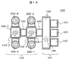
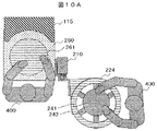
本発明の実施例に係る真空処理装置ついて、図1A〜図10Bを用いて説明する。図1Aは本実施例に係る真空処理装置の概略上面図(一部透視)であり、図1Bは図1Aに示す真空処理装置の概略斜視図である。本実施例の真空処理装置100であるプラズマ処理装置は、大気ブロック101と真空ブロック102とを有する。大気ブロック101は、大気圧下で半導体ウエハ等の被処理物(試料)を搬送、収納位置決め等をする部分であり、真空ブロック102は大気圧から減圧された圧力下でウエハ等の試料を搬送し、処理等を行ない、試料を載置した状態で圧力を上下させる部分である。
Hereinafter, an example explains. In the drawings, the same reference numerals indicate the same components.
(Example)
A vacuum processing apparatus according to an embodiment of the present invention will be described with reference to FIGS. 1A to 10B. 1A is a schematic top view (partially see through) of the vacuum processing apparatus according to the present embodiment, and FIG. 1B is a schematic perspective view of the vacuum processing apparatus shown in FIG. 1A. The plasma processing apparatus which is the
大気ブロック101は、大気搬送室106と、この大気搬送室106の前面側に取付けられ、処理用又はクリーニング用の試料が収納されているカセットがその上面に載せられる複数のカセット台107を備えている。大気ブロック101は、カセット台107上の各カセットの内部に収納された処理用またはクリーニング用のウエハが大気搬送室106の背面に連結された真空ブロック102との間でやりとりされる箇所であり、大気搬送室106内部にはこのようなウエハの搬送のためにウエハ保持用のアームを備えた大気搬送ロボット109が配置されている。
The
真空ブロック102は減圧して試料を処理する複数の真空処理室200−1、200−2、200−3、200−4と、これらの真空処理室と連結されその内部で試料を減圧下で搬送する真空搬送ロボット110−1、110−2を備えた真空搬送室104−1、104−2、及びこの真空搬送室104−1と大気搬送室106を接続するロック室105、真空搬送室104−1と真空搬送室104−2を接続する搬送中間室108とを備えている。この真空ブロック102は、その内部は減圧されて高い真空度の圧力に維持可能なユニットで構成されている。これら大気搬送ロボットや真空搬送ロボットの動作や、真空処理室における処理の制御は、制御装置により行われる。
The
図3Aは、図1Aに示す実施例の真空処理室の構成の概略を示す縦断面図である。特に、図3Aでは真空処理室200における真空処理室の構成の略図を示している。本実施例では同一構造の真空処理室を配置しているが、他の構造を有する真空処理室を組み込んでもよい。
FIG. 3A is a longitudinal sectional view showing an outline of the configuration of the vacuum processing chamber of the embodiment shown in FIG. 1A. In particular, FIG. 3A shows a schematic diagram of the configuration of the vacuum processing chamber in the
図3Aに示す真空処理室は、上部容器230や下部容器250を含む真空容器と、これに連結されて配置された下方の排気ポンプ270と、上方の第1高周波電源201およびソレノイドコイル206とを備えている。上部容器や下部容器は水平断面形状が円形状の内壁を有し、その内部の中央部には、円筒形状の試料台241が配置されている。上部容器や下部容器の外壁は真空隔壁を構成している。試料台241は試料台ベース242に設けられた支持梁により保持されており、支持梁は試料台の鉛直方向の中心を軸として軸対称に配置(即ち、試料台の中心軸290に対するガス流路形状が略同軸軸対称)されている。上部容器230内の試料台241上の空間のガス等(処理ガス、プラズマ中の粒子や反応生成物)が、この支持梁同士の間の空間を通り下部容器250を介して排気されるため、被処理物(試料)300が載置された試料台241の周方向におけるガスの流れが均一になり、被処理物300に対する均一な処理が可能となる。なお、試料台ベース242は支持梁を備えたリング形状を有しており、このリング部分が真空容器である下部容器と上部上記の周囲で保持され、真空シールされるため、試料台等の重量が増加しても対応可能である。
The vacuum processing chamber shown in FIG. 3A includes a vacuum vessel including an
真空処理室は、本実施例ではベースプレート260上に順次積層された円筒形状の下部容器250、支持梁を備えたリング状の試料台ベース242、円筒形状の上部容器230、アースリング225、円筒形状の放電ブロック224、ガス導入リング204を含む複数の部材により構成されており、それぞれの部材はOリング207により真空シールされている。放電ブロック224の内側には円筒形状の石英内筒205が配置されている。また、試料台ベース242には試料台底部蓋245を有する試料台241が固定されて試料台ユニットを構成し、ヒータ222が取り付けられた放電ブロック224は放電ブロックベース221に固定されて放電ブロックユニットを構成している。また、上部容器230、下部容器250、ベースプレート260はフランジ部を有し、上部容器230と下部容器250はフランジ部でベースプレート260にそれぞれネジ止めされている。なお、本実施例では、真空処理室を構成する部材は円筒形状を有するが、外壁形状に関しては水平断面形状が円形ではなく矩形であっても、他の形状であってもよい。
In this embodiment, the vacuum processing chamber includes a cylindrical
真空処理室の上方には、真空容器を構成する円板形状を有する蓋部材202とその下方に真空処理室の天井面を構成する円板形状のシャワープレート203が配置されている。これらの蓋部材202とシャワープレート203は石英等の誘電体製の部材であり、マイクロ波やUHF、VHF波等の高周波電界が透過可能に構成されており、上方に配置された第1高周波電源からの電界がこれらを通り真空処理室内に供給される。また、真空容器の外側側壁の外周にはこれを囲んで磁場の形成手段(ソレノイドコイル)206が配置され発生された磁場を真空処理室内に供給可能に構成されている。
Above the vacuum processing chamber, a disc-shaped
シャワープレート203には、複数の貫通孔である処理用ガスの導入孔が配置されており、ガス導入リング204から導入された処理用ガスがこの導入孔を通して真空処理室内に供給される。シャワープレート203の導入孔は、試料台241の上面である試料の載置面の上方であって試料台241の中心軸290の回りの軸対称の領域に複数個配置されており、均等に配置された導入孔を通り所定の組成を有して異なるガス成分から構成された処理用ガスが真空処理室内に導入される。
The
真空処理室内部に導入された処理用ガスは、電界形成手段である第1高周波電源201と磁界形成手段であるソレノイドコイル206により発生する電磁波及び磁場が真空処理室内に供給されることにより励起されて試料台241上方の放電ブロック224内の空間においてプラズマ化される。このとき、処理用ガス分子は電子とイオンに電離されたり、あるいはラジカルに解離されたりする。このプラズマが生成される領域には、第1温度コントローラ223に接続されたヒータ222が取り付けられ、放電ブロックベース221上に配置された放電ブロック224が設けられており、プラズマと接触するプ石英内筒205を加熱することができる。これにより、石英内筒205や放電ブロック224への反応生成物の付着を低減することができる。このため、これらの部材は定常メンテナンスの対象から外すことができる。
The processing gas introduced into the vacuum processing chamber is excited by supplying the electromagnetic wave and magnetic field generated by the first high-
ウエハを載置する試料台241は、真空処理室の内部にこのシャワープレート203の中心軸290と合致するように配置される。プラズマによる処理を行う際は被処理物300であるウエハは試料台241の上面である円形の載置面に載せられてこの面を構成する誘電体の膜静電気により吸着されて保持(静電チャック)された状態で処理が行われる。本実施例では、試料である半導体ウエハは直径450mmのものを使用することを考慮して円筒形状の真空処理室の内径は800mmとした。但し、この寸法以下(600mm程度)とすることもできる。
The
また、試料台241内部に配置された電極には高周波バイアス電源(第2高周波電源)243が接続されており、供給される高周波電力により試料台241及びこの上に載せられた試料300の上方に形成される高周波バイアスによりプラズマ中の荷電粒子を試料の表面に誘引して衝突させることによる物理反応と前記ラジカルとウエハ表面との化学反応との相互反応によりエッチング処理が進行する。また、試料台の温度は第2温度コントローラ244により所望の温度に制御することができる。試料台241への高周波バイアスの印加や試料台241の温度制御は、支持梁を含む試料台ベース242内部に形成された空洞内に配置された電源用配線コードや温度制御用の配線コード或いは冷媒用配管を介して行われる。なお、図示してはいないが、前記配線コードの他、温度センサーや静電チャック用配線コードも含むことができる。試料台241の周辺に配置される上部容器230には反応生成物が付着し易いため、定常メンテナンスの対象部材である。
A high-frequency bias power source (second high-frequency power source) 243 is connected to the electrode disposed inside the
真空処理室の下方にはその底部と排気開口を有するベースプレート260を介して連結された排気ポンプ270が配置されている。ベースプレート260に設けられた排気開口は、試料台241の真下に配置され、排気開口上に配置された略円板形状を有する排気部蓋261をシリンダ262により上下に移動することにより排気コンダクタンスを調整することができ、排気ポンプ270により真空処理室外に排出される内部のガスやプラズマ、生成物の量、速度が調節される。この排気部蓋261は被処理物を処理する際には開放されており、処理用ガスの供給と共に排気ポンプ270等の排気手段の動作とのバランスにより、真空処理室内部の空間の圧力は所望の真空度に保持される。本実施例では、処理中の圧力は、0.1〜4Paの範囲で予め定められた値に調節される。排気ポンプとしては分子ターボポンプを用いた。なお、排気部蓋261は、メンテナンスの際には閉じて排気ポンプをOリングにより真空シールすることができる。なお、符号111は第1ゲートバルブ、符号112は第2ゲートバルブ、符号115はバルブボックス、符号280は支柱である。
An
真空処理室内に導入された処理用ガス、及びプラズマや処理の際の反応生成物は排気ポンプ270等の排気手段の動作により真空処理室上部から試料台241の外周側の空間を通り、下部容器250を介して下方のベースプレート260に設けられた開口まで移動する。下部容器250は反応生成物が付着し易いため、定常メンテナンスの対象部材となる。
The processing gas introduced into the vacuum processing chamber, the plasma, and the reaction products during processing pass from the upper portion of the vacuum processing chamber to the outer peripheral side of the sample table 241 by the operation of the exhaust means such as the
エッチング処理中の真空処理室内部の圧力は真空計(図示せず)にて監視され、排気部蓋261によって排気速度を制御することで真空処理室内部の圧力を制御している。これらの処理用ガスの供給や電界形成手段、磁界形成手段、高周波バイアス、排気手段の動作は図示しない通信可能に接続された制御装置により調節される。
The pressure inside the vacuum processing chamber during the etching process is monitored by a vacuum gauge (not shown), and the pressure inside the vacuum processing chamber is controlled by controlling the exhaust speed by the
プラズマ処理に使用する処理用ガスには、各プロセスの条件毎に単一種類のガス、あるいは複数種類のガスを最適な流量比で混合されたガスが用いられる。この混合ガスは、その流量がガス流量制御器(図示せず)により調節されこれと連結されたガス導入リング204を介して真空容器上部の真空処理室上方のシャワープレート203と蓋部材202との間のガス滞留用の空間に導入される。本実施例ではステンレス製のガス導入リングを用いた。
As the processing gas used for the plasma processing, a single kind of gas or a gas obtained by mixing a plurality of kinds of gases at an optimum flow rate ratio is used for each process condition. The flow rate of the mixed gas is adjusted between a
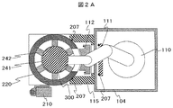
次に、被処理物の真空処理室内への搬入、真空処理室からの搬出の手順について図2A〜図3Bを用いて説明する。先ず大気ブロックにおいて、カセットから大気搬送ロボットにより取り出されたウエハはロック室を経て真空搬送室104へ搬送される。図2Bは、真空搬送室104にウエハ300が搬入された状態を示す。真空処理室と真空搬送室とは第1ゲートバルブ111と第2ゲートバルブとを介して接続されている。本図ではゲートバルブは両方とも閉じられており、Oリング207で真空シールされている。符号115はバルブボックス、符号210は旋回リフター(移動手段)である。旋回リフター210については後述する。次に、真空処理室と真空搬送室の圧力を揃えた上で、図2Aに示すように、アームを備えた真空搬送ロボット110を用いて真空搬送室104から真空処理室へウエハ300を搬入する。このとき、第1及び第2ゲートバルブ111、112が両者とも開の状態である。次いで、図3Aに示すように、ウエハ300を真空処理室内の試料台241に載置し、真空搬送ロボットは真空搬送室へ戻り、第1、第2ゲートバルブ111、112は閉じられる。
Next, procedures for carrying in the workpiece into the vacuum processing chamber and carrying it out of the vacuum processing chamber will be described with reference to FIGS. 2A to 3B. First, in the atmospheric block, the wafer taken out from the cassette by the atmospheric transfer robot is transferred to the
真空処理室内においてウエハ300への処理が完了すると、真空処理室と真空搬送室との圧力を調整後、図3Bに示すように第1、第2ゲートバルブ111、112を開状態とする。引き続き、図2Aに示すように真空搬送ロボット110を用いて試料台241からウエハ300を取り外す。引き続き、図2Bに示すようにウエハ300を真空搬送室104へ搬入する。その後、ウエハ300は他の真空処理室で処理された後、或いは処理されることなく、ロック室を介してカセットへ搬送される。
When the processing on the
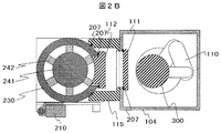
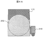
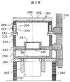
次に、定常メンテナンスの手順について図4A〜図10Bを用いて説明する。図4A、図4Bは、図3Aや図3Bに示した真空処理室の構成からソレノイドコイル206と第1高周波電源201を取り除くと共に、排気ポンプ270に接続されるベースプレート260の開口部を排気部蓋261で塞ぎ真空シールした構成を示し、図4Aは平面図、図4Bは断面図である。排気部蓋261により排気ポンプ270を真空シールし、排気ポンプ270を稼働させておくことにより、メンテナンス後の真空処理室の立ち上げ時間を短縮することができる。なお、図4Bに示す断面図は、旋回リフター210を説明するために、図3Aや図3Bとは見る方向が異なる。すなわち、図3Aや図3Bに示す断面図では、図4Aに示す平面図において右側から見た図であるが、図4Bに示す断面図では、図4Aに示す平面図において下側から見た図となっている。図5B〜図10Bに示す断面図は、図4Bに示す断面図と同じ方向から見た図である。
Next, the routine maintenance procedure will be described with reference to FIGS. 4A to 10B. 4A and 4B show that the
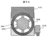
次に、図5A、図5Bに示すように、石英板202、その下方のシャワープレート203及び石英内筒205を上方に移動させて取り外す。これにより、真空処理室の上端にはガス導入リング204が露出する。また、真空処理室内部には、試料台241と試料台ベース242の支持梁の部分が露出する。
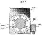
次いで、図6A、図6Bに示すように、ガス導入リング204を上方へ移動させて取り外す。
Next, as shown in FIGS. 5A and 5B, the
Next, as shown in FIGS. 6A and 6B, the
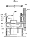
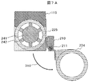
引き続き、図7A、図7Bに示すように、旋回リフター210の可動部に固定された放電ブロックベース221と、その上に取り付けられた放電ブロック224及びヒータ222を含む放電ブロックユニット220を、矢印310に示すように旋回軸211を中心として上方へ移動後、水平に反時計方向に旋回させることにより鉛直上方から見て真空処理室の領域外へ移動する。本実施例では放電ブロックユニットを反時計方向に旋回したが、旋回リフターの位置を反対側(図中右側配置を左側配置)に変更して時計方向に旋回させる構成とすることもできる。放電ブロックユニット220を上方に移動する距離は、アースリング225の突起部を越える高さ以上とする。本実施例では5cmとしたが、これに限定されない。なお、アースリングの突起部の高さが低い場合には、Oリング207が放電ブロックユニット220或いはアースリング225から離れる高さ(数cm)以上とする。又、旋回角度は180度としたが、90度以上270度以下とすることができる。但し、作業性を考慮すると180度±20度が好適である。定常メンテナンスの対象ではない放電関連部材を放電ブロックユニット220として纏めて旋回することにより、真空処理室の上部からこれらを迅速・容易に回避させることができる。放電ブロックユニット220を回避させることにより、真空処理室の上端にはアースリング225が露出する。
Subsequently, as shown in FIGS. 7A and 7B, a
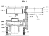
次に、図8A、図8Bに示すように、アースリング225及び主要な定常メンテナンス対象部材である上部容器230を上方へ移動させて取り外す。すなわち、スワップ(交換)可能な状態で容易に上部容器230を取り外すことができる。本実施例においては真空処理室を構成する真空隔壁自体(上部容器)が交換可能である。これにより、真空処理室を解体してからの上部容器230のメンテナンス時間を最小限に抑えることができる。なお、メンテナンスを行う際、第1ゲートバルブは閉とし、第2ゲートバルブは開としておく。第1ゲートバルブ111は閉じて真空搬送室104を真空シール状態とすることにより、他の真空処理室での処理が可能となり、真空処理装置としての稼働率の低下を最小限に抑えることができる。一方、第2ゲートバルブ112を開放状態とすることにより、上部容器230とバルブボックス115とを分離することができる。上部容器230の取り外しは、上部容器230とベースプレート260とをフランジ部で固定していたネジを取りはずしてから行った。放電ブロックユニットの移動は、旋回リフターを制御する制御装置により行った。この制御装置は旋回リフター専用でもよいが、真空処理装置全体の制御装置の一部として組み込んでも良い。上部容器230を取り外すことにより、試料台241と支持梁の他、試料台ベース242のリング部分が露出する。
Next, as shown in FIGS. 8A and 8B, the
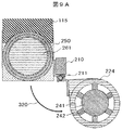
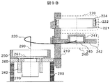
次いで、図9A、図9Bに示すように、旋回リフター210の可動部に固定された試料台ベース242と、その上に取り付けられた試料台241及び試料台底部蓋245を含む試料台ユニット240を、矢印320に示すように旋回軸211を中心として上方へ移動後、水平に反時計方向に旋回させることにより鉛直上方から見て真空処理室の領域外へ移動する。本実施例では試料台ユニットを反時計方向に旋回したが、旋回リフターの位置を反対側(図中右側配置を左側配置)に変更して時計方向に旋回させる構成とすることもできる。試料台ユニット240を上方に移動する距離は、Oリング207が試料台ユニット240或いは下部容器250から剥がれる高さ以上とする。本実施例では2cmとしたが、これに限定されない。又、旋回角度は放電ブロックユニット220と同じとなるように設定することが望ましい。これにより、鉛直上方から見た場合、放電ブロックユニット220と試料台ユニット240の両者の合計面積を小さくすることができる。定常メンテナンスの対象ではない試料台関連部材を試料台ユニット240として纏めて旋回することにより、真空処理室の上部からこれらを迅速・容易に回避させることができる。試料台ユニット240の移動は、旋回リフターを制御する制御装置により行った。この制御装置は旋回リフター専用でもよいが、真空処理装置全体の制御装置の一部として組み込んでも良い。試料台ユニット240を回避させることにより、真空処理室の上端には下部容器250が露出する。また、排気部蓋261の全表面が露出する。
Next, as shown in FIGS. 9A and 9B, a
引き続き、下部容器250とベースプレート260とをフランジ部で固定していたネジは取りはずした後、図10A、図10Bに示すように、主要な定常メンテナンス対象部材である下部容器250を上方へ移動させて取り外す。すなわち、スワップ(交換)可能な状態で容易に下部容器250を取り外すことができる。これにより、真空処理室を解体してからの下部容器250のメンテナンス時間を最小限に抑えることができる。下部容器250を取り外した後、ベースプレート260の表面や排気部蓋261の表面の点検・整備を行う。ベースプレート260の露出部は下部容器250で覆われていたため反応生成物の付着が少なく、また、排気部蓋261の上部表面は、被処理物を処理する際には試料台の下に配置されており、反応生成物の付着は少ないが、必要に応じて清掃することができる。ベースプレート260の周辺には真空処理室を構成する壁等(メンテナンス上の障害物)が無くフラットなため、作業者400(図10Bでは図示せず)のメンテナンスの作業効率を向上させることができる。
Subsequently, after removing the screws that have fixed the
定常メンテナンス対象の部材の清掃や、点検・整備、交換(特に、上部容器と下部容器)を行った後、上記説明と逆の手順で組み立てられ、真空処理に供せられる。 After cleaning, inspection, maintenance, and replacement (particularly, the upper container and the lower container) of the members subject to regular maintenance, they are assembled in the reverse order of the above description and subjected to vacuum processing.
次に、非定常メンテナンスの手順について説明する。非定常メンテナンスの対象部材は主に放電ブロックユニット220を構成する部材と試料台ユニット240を構成する部材である。放電ブロックユニット220を構成する部材の場合には、図7A、図7Bに示したように放電ブロックユニット220を上方へ持ち上げ、水平方向に旋回した後、所望の方向から、ヒータ222の点検・交換、放電ブロック224の内壁の点検、清掃等のメンテナンスを行うことができる。放電ブロックユニット220は、他の真空処理室を構成する部材から回避されているため作業効率の向上を図ることができる。
Next, the procedure of unsteady maintenance will be described. The target members of the unsteady maintenance are mainly members constituting the
試料台ユニット240を構成する部材の場合には、図9A、図9Bに示したように試料台ユニットを上方へ持ち上げ、水平方向に旋回した後、図10Bに示すように試料台底部蓋を取り外して所望の方向から、各種電源コードやセンサーの配線、温度調節用部品等のメンテナンスを行うことができる。支持梁内部の空洞には、被処理物を試料台に静電吸着させるため用いられる配線コード、試料台へ高周波バイアスを印加するために用いられる配線コード、試料台の温度を制御するために用いられる配線コード或いは冷媒用配管、試料台の温度を検出するために用いられる配線コードの中の少なくとも一つが配置されており、それらも非定常メンテナンスの対象となる。なお、放電ブロックユニット220が作業の障害となる場合には、鉛直上方から見て真空処理室が配置された領域、又はその近傍迄時計方向に旋回させることができる。これにより、試料台ユニット240の作業効率の向上を図ることができる。また、放電ブロックユニットと試料台ユニットの旋回角度を適当にズラせることにより、両ユニットを同時にメンテナンスすることができるため、作業効率が向上する。
In the case of the members constituting the
なお、本実施例では、放電ブロックユニットや試料台ユニットを、上方に持ち上げた後水平方向に旋回したが、持ち上げた後水平方向に直線状に引き出す構成としてもよい。これにより、移動範囲を最小限とすることができる。また、移動機構の構成の簡略化が図れる。但し、水平方向への旋回の方がメンテナンスの作業空間を確保する上で有利である。 In the present embodiment, the discharge block unit and the sample stage unit are swung in the horizontal direction after being lifted upward. However, the discharge block unit and the sample stage unit may be configured to be drawn out linearly in the horizontal direction after being lifted. Thereby, the movement range can be minimized. In addition, the configuration of the moving mechanism can be simplified. However, turning in the horizontal direction is more advantageous for securing a work space for maintenance.
また、本実施例では、上部容器だけでなく下部容器も交換したが、下部容器内面を覆うようにライナー(カバー)を取り付け、当該ライナーを交換する構成としてもよい。 In this embodiment, not only the upper container but also the lower container is replaced. However, a liner (cover) may be attached so as to cover the inner surface of the lower container, and the liner may be replaced.
また、本実施例では旋回リフターを1つとし、放電ブロックユニットと試料台ユニットとを同一方向に旋回させたが、作業領域を確保できる場合には旋回リフターを2つ設け、それぞれ別々の方向に旋回させることもできる。放電ブロックユニット用の旋回リフターと試料台ユニット用の旋回リフターとをそれぞれ設けることにより、それぞれのユニットの高さを自由に設定することができる。また、作業者をより多く配置することができるため作業の同時進行を容易に行うことが可能となり、短時間で作業を終了することができ、作業効率が向上する。 Further, in this embodiment, one swivel lifter is used, and the discharge block unit and the sample stage unit are swung in the same direction. However, when the work area can be secured, two swivel lifters are provided, each in a different direction. It can also be turned. By providing the swivel lifter for the discharge block unit and the swivel lifter for the sample stage unit, the height of each unit can be set freely. In addition, since a larger number of workers can be arranged, it is possible to easily perform the simultaneous progress of the work, the work can be completed in a short time, and work efficiency is improved.
また、上記実施例では、旋回リフターを用いて移動を行う放電ブロックユニットや試料台ユニット以外の構成部品の移動は人手で行ったが、クレーン等の起重機を用いても良い。 Moreover, in the said Example, although movement of components other than the discharge block unit and sample stage unit which move using a turning lifter was performed manually, you may use hoists, such as a crane.
また、本実施例では、真空処理装置としてECRタイプの真空処理装置を用いたが、これに限らず、ICPタイプの装置等々にも適用することができる。また、リンク方式で配列された真空処理室を備えた真空処理装置を用いたが、これに限らず、クラスター方式の装置にも適用することができる。 In this embodiment, an ECR type vacuum processing apparatus is used as the vacuum processing apparatus. However, the present invention is not limited to this, and can be applied to an ICP type apparatus. Moreover, although the vacuum processing apparatus provided with the vacuum processing chambers arranged in the link system is used, the present invention is not limited to this and can be applied to a cluster system apparatus.
以上説明したように、本実施例によれば、被処理物が大口径化した場合であっても、処理の均一性が良好で(同軸の軸対称排気)で、かつ定常的なメンテナンスだけでなく、非定常的なメンテナンスも効率よく行うことが可能な真空処理装置を提供することができる。 As described above, according to this embodiment, even when the workpiece has a large diameter, the processing uniformity is good (coaxial axisymmetric exhaust) and only routine maintenance is required. In addition, it is possible to provide a vacuum processing apparatus capable of efficiently performing unsteady maintenance.
なお、本発明は上記した実施例に限定されるものではなく、様々な変形例が含まれる。例えば、上記した実施例は本発明を分かりやすく説明するために詳細に説明したものであり、必ずしも説明した全ての構成を備えるものに限定されるものではない。また、ある構成の一部を他の構成に置き換えることも可能であり、また、ある構成に他の構成を加えることも可能である。 In addition, this invention is not limited to an above-described Example, Various modifications are included. For example, the above-described embodiments have been described in detail for easy understanding of the present invention, and are not necessarily limited to those having all the configurations described. Further, a part of a certain configuration can be replaced with another configuration, and another configuration can be added to a certain configuration.
100・・・真空処理装置、101・・・大気ブロック、102・・・真空ブロック、104、104−1、104−2・・・真空搬送室、105・・・ロック室、106・・・大気搬送室、107・・・カセット台、108・・・搬送中間室、109・・・大気搬送ロボット、110、110−1、110−2・・・真空搬送ロボット、111・・・第1ゲートバルブ、112・・・第2ゲートバルブ、115・・・バルブボックス、200、200−1、200−2、200−3、200−4・・・真空処理室、201・・・第1高周波電源、202・・・蓋部材(石英板)、203・・・シャワープレート、204・・・ガス導入リング、205・・・石英内筒、206・・・コイル、207・・・Oリング、210・・・旋回リフター、211・・・旋回軸、220・・・放電ブロックユニット、221・・・放電ブロックベース、222・・・ヒータ、223・・・第1温度コントローラ、224・・・放電ブロック、225・・・アースリング、230・・・上部容器、240・・・試料台ユニット、241・・・試料台、242・・・試料台ベース、243・・・第2高周波電源、244・・・第2温度コントローラ、245・・・試料台底部蓋、250・・・下部容器、260・・・ベースプレート、261・・・排気部蓋、262・・・シリンダ、270・・・排気ポンプ、280・・・支柱、290・・・中心軸、300・・・被処理物(ウエハ、試料)、310・・・放電ブロックユニットの動く方向、320・・・試料台ユニットの動く方向、400・・・作業者。
DESCRIPTION OF
Claims (15)
前記真空処理室は、
排気開口を有するベースプレートと、
前記ベースプレートの上に配置され、水平断面の内壁が円形状を有する下部容器と、
前記下部容器の上に配置され、被処理物を載置する試料台および前記試料台を支持する支持梁であって、前記試料台の中心軸に対して軸対称に配置された支持梁を備えたリング状の試料台ベースを有する試料台ユニットと、
前記試料台ユニットの上に配置され、水平断面の内壁が円形状を有する上部容器と、
前記試料台ベースに固定され、前記試料台ユニットを上下方向及び水平方向に移動可能な移動手段と、を備えることを特徴とする真空処理装置。 A vacuum transfer chamber and a vacuum processing chamber connected to the vacuum transfer chamber;
The vacuum processing chamber is
A base plate having an exhaust opening;
A lower container disposed on the base plate, the inner wall of the horizontal section having a circular shape;
A sample table placed on the lower container and on which a workpiece is placed and a support beam for supporting the sample table, the support beam being arranged symmetrically with respect to the central axis of the sample table A sample stage unit having a ring-shaped sample stage base;
An upper container disposed on the sample stage unit, the inner wall of the horizontal section having a circular shape;
A vacuum processing apparatus comprising: a moving means fixed to the sample stage base and capable of moving the sample stage unit in the vertical direction and the horizontal direction.
前記ベースプレートの前記排気開口は、前記試料台の真下に配置されていることを特徴とする真空処理装置。 The vacuum processing apparatus according to claim 1, wherein
The vacuum processing apparatus according to claim 1, wherein the exhaust opening of the base plate is disposed directly below the sample stage.
前記ベースプレートと、前記下部容器と、前記試料台ユニットと、前記上部容器との間は、互いに真空シールされていることを特徴とする真空処理装置。 The vacuum processing apparatus according to claim 1, wherein
The vacuum processing apparatus, wherein the base plate, the lower container, the sample stage unit, and the upper container are vacuum-sealed with each other.
前記真空搬送室と前記真空処理室との間にバルブボックスが配置され、
前記真空搬送室は、前記被処理物を前記真空処理室との間で搬送する第1開口部と前記第1開口部を開閉する第1ゲートバルブとを有し、
前記真空処理室は前記被処理物を前記真空搬送室との間で搬送する第2開口部を有し、
前記バルブボックスは、前記第1開口部と前記第2開口部を接続し、前記第2開口部を開閉する第2ゲートバルブを有することを特徴とする真空処理装置。 The vacuum processing apparatus according to claim 1, wherein
A valve box is disposed between the vacuum transfer chamber and the vacuum processing chamber,
The vacuum transfer chamber has a first opening for transferring the object to be processed with the vacuum processing chamber and a first gate valve for opening and closing the first opening,
The vacuum processing chamber has a second opening for transferring the object to be processed to and from the vacuum transfer chamber,
The vacuum processing apparatus, wherein the valve box includes a second gate valve that connects the first opening and the second opening and opens and closes the second opening.
前記真空処理装置のメンテナンスの際、前記第1ゲートバルブは閉状態、前記第2ゲートバルブは開状態とされるものであることを特徴とする真空処理装置。 The vacuum processing apparatus according to claim 4, wherein
The vacuum processing apparatus is characterized in that the first gate valve is closed and the second gate valve is opened during maintenance of the vacuum processing apparatus.
前記試料台ユニットは、前記移動手段により上方へ持ち上げられた後、水平方向に旋回されるものであることを特徴とする真空処理装置。 The vacuum processing apparatus according to claim 1, wherein
2. The vacuum processing apparatus according to claim 1, wherein the sample stage unit is lifted upward by the moving means and then pivoted in the horizontal direction.
前記試料台ユニットは、前記移動手段により上方へ持ち上げられた後、水平方向に直線的に移動されるものであることを特徴とする真空処理装置。 The vacuum processing apparatus according to claim 1, wherein
The vacuum processing apparatus, wherein the sample stage unit is lifted upward by the moving means and then linearly moved in the horizontal direction.
前記真空処理装置のメンテナンスの際、前記上部容器及び前記下部容器は交換されるものであることを特徴とする真空処理装置。 The vacuum processing apparatus according to claim 1, wherein
The vacuum processing apparatus, wherein the upper container and the lower container are exchanged during maintenance of the vacuum processing apparatus.
前記下部容器は内部にインナーを有し、
前記真空処理装置のメンテナンスの際、前記下部容器のインナー及び前記上部容器は交換されるものであることを特徴とする真空処理装置。 The vacuum processing apparatus according to claim 1, wherein
The lower container has an inner inside,
The vacuum processing apparatus according to claim 1, wherein the inner part of the lower container and the upper container are exchanged during maintenance of the vacuum processing apparatus.
前記ベースプレートの排気開口は、前記真空処理装置の稼働中は開状態とされ、前記真空処理装置のメンテナンスの際には閉状態とされるものであることを特徴とする真空処理装置。 The vacuum processing apparatus according to claim 1, wherein
The vacuum processing apparatus according to claim 1, wherein the exhaust opening of the base plate is opened during the operation of the vacuum processing apparatus and is closed during maintenance of the vacuum processing apparatus.
前記支持梁の内部に設けられた空洞には、前記被処理物を前記試料台に静電吸着させるため用いられる配線コード、前記試料台へ高周波バイアスを印加するために用いられる配線コード、前記試料台の温度を制御するために用いられる配線コード或いは冷媒用配管、前記試料台の温度を検出するために用いられる配線コードの中の少なくとも一つが配置されていることを特徴とする真空処理装置。 The vacuum processing apparatus according to claim 1, wherein
In the cavity provided inside the support beam, a wiring cord used for electrostatically adsorbing the object to be processed to the sample table, a wiring code used for applying a high frequency bias to the sample table, the sample A vacuum processing apparatus, wherein at least one of a wiring cord or a refrigerant pipe used for controlling the temperature of the table and a wiring code used for detecting the temperature of the sample table is arranged.
前記真空処理室は、ドライエッチング処理が行われるものであることを特徴とする真空処理装置。 The vacuum processing apparatus according to claim 1, wherein
The vacuum processing apparatus is characterized in that a dry etching process is performed in the vacuum processing chamber.
前記真空処理室は、
排気開口を有するベースプレートと、
前記ベースプレートの上に配置され、水平断面の内壁が円形状を有する下部容器と、
前記下部容器の上に配置され、被処理物を載置する試料台および前記試料台を支持する支持梁であって、前記試料台の中心軸に対して軸対称に配置された支持梁を備えたリング状の試料台ベースを有する試料台ユニットと、
前記試料台ユニットの上に配置され、水平断面の内壁が円形状を有する上部容器と、
前記上部容器の上に配置され、放電ブロックベース及び前記放電ブロックベースに取り付けられ、水平断面の内壁が円形状の放電ブロックを含み、前記放電ブロックの内側でプラズマが生成される放電ブロックユニットと、
前記試料台ベース及び前記放電ブロックベースにそれぞれ個別に固定され、前記試料台ユニット及び前記放電ブロックユニットをそれぞれ個別に上下方向及び水平方向に移動可能な移動手段と、を備えることを特徴とする真空処理装置。 In a vacuum processing apparatus having an atmospheric block and a vacuum block having a vacuum transfer chamber and a vacuum processing chamber connected to the vacuum transfer chamber,
The vacuum processing chamber is
A base plate having an exhaust opening;
A lower container disposed on the base plate, the inner wall of the horizontal section having a circular shape;
A sample table placed on the lower container and on which a workpiece is placed and a support beam for supporting the sample table, the support beam being arranged symmetrically with respect to the central axis of the sample table A sample stage unit having a ring-shaped sample stage base;
An upper container disposed on the sample stage unit, the inner wall of the horizontal section having a circular shape;
A discharge block unit disposed on the upper vessel, attached to the discharge block base and the discharge block base, wherein the inner wall of the horizontal cross section includes a circular discharge block, and plasma is generated inside the discharge block;
And a moving means that is individually fixed to the sample stage base and the discharge block base and capable of individually moving the sample stage unit and the discharge block unit in the vertical direction and the horizontal direction, respectively. Processing equipment.
前記試料台ユニット及び前記放電ブロックユニットは、前記移動手段によりそれぞれ個別に上方へ持ち上げられた後、水平方向に旋回されるものであることを特徴とする真空処理装置。 The vacuum processing apparatus according to claim 13, wherein
The vacuum processing apparatus according to claim 1, wherein the sample stage unit and the discharge block unit are individually lifted upward by the moving means and then turned in the horizontal direction.
前記試料台ユニット及び前記放電ブロックユニットは、前記移動手段によりそれぞれ個別に上方へ持ち上げられた後、水平方向に直線的に移動されるものであることを特徴とする真空処理装置。 The vacuum processing apparatus according to claim 1, wherein
The vacuum processing apparatus, wherein the sample stage unit and the discharge block unit are individually lifted upward by the moving means and then linearly moved in the horizontal direction.
Priority Applications (8)
| Application Number | Priority Date | Filing Date | Title |
|---|---|---|---|
| JP2014012027A JP6293499B2 (en) | 2014-01-27 | 2014-01-27 | Vacuum processing equipment |
| TW103127079A TWI600101B (en) | 2014-01-27 | 2014-08-07 | Vacuum processing equipment |
| TW106122760A TWI644382B (en) | 2014-01-27 | 2014-08-07 | Vacuum processing device |
| KR1020140107805A KR101774532B1 (en) | 2014-01-27 | 2014-08-19 | Vacuum processing apparatus |
| CN201711439328.3A CN108155082B (en) | 2014-01-27 | 2014-08-19 | Method for operating vacuum processing apparatus |
| CN201410408799.8A CN104810305B (en) | 2014-01-27 | 2014-08-19 | Vacuum treatment installation |
| US14/468,397 US11710619B2 (en) | 2014-01-27 | 2014-08-26 | Vacuum processing apparatus |
| KR1020170109634A KR101835438B1 (en) | 2014-01-27 | 2017-08-29 | Vacuum processing apparatus |
Applications Claiming Priority (1)
| Application Number | Priority Date | Filing Date | Title |
|---|---|---|---|
| JP2014012027A JP6293499B2 (en) | 2014-01-27 | 2014-01-27 | Vacuum processing equipment |
Related Child Applications (1)
| Application Number | Title | Priority Date | Filing Date |
|---|---|---|---|
| JP2018023776A Division JP6475877B2 (en) | 2018-02-14 | 2018-02-14 | Vacuum processing equipment |
Publications (3)
| Publication Number | Publication Date |
|---|---|
| JP2015141908A true JP2015141908A (en) | 2015-08-03 |
| JP2015141908A5 JP2015141908A5 (en) | 2017-03-02 |
| JP6293499B2 JP6293499B2 (en) | 2018-03-14 |
Family
ID=53679672
Family Applications (1)
| Application Number | Title | Priority Date | Filing Date |
|---|---|---|---|
| JP2014012027A Active JP6293499B2 (en) | 2014-01-27 | 2014-01-27 | Vacuum processing equipment |
Country Status (5)
| Country | Link |
|---|---|
| US (1) | US11710619B2 (en) |
| JP (1) | JP6293499B2 (en) |
| KR (2) | KR101774532B1 (en) |
| CN (2) | CN108155082B (en) |
| TW (2) | TWI644382B (en) |
Cited By (5)
| Publication number | Priority date | Publication date | Assignee | Title |
|---|---|---|---|---|
| KR20170088760A (en) | 2016-01-25 | 2017-08-02 | 도쿄엘렉트론가부시키가이샤 | Substrate processing apparatus |
| KR20180087104A (en) | 2017-01-23 | 2018-08-01 | 가부시키가이샤 히다치 하이테크놀로지즈 | The vacuum processing apparatus |
| JP2019096906A (en) * | 2019-03-01 | 2019-06-20 | 株式会社日立ハイテクノロジーズ | Vacuum processing apparatus |
| KR20190101850A (en) | 2018-02-23 | 2019-09-02 | 가부시키가이샤 히다치 하이테크놀로지즈 | Vacuum processing apparatus |
| JP7296739B2 (en) | 2019-01-31 | 2023-06-23 | 東京エレクトロン株式会社 | Processing device and method of operating the processing device |
Families Citing this family (8)
| Publication number | Priority date | Publication date | Assignee | Title |
|---|---|---|---|---|
| US9293303B2 (en) * | 2013-08-30 | 2016-03-22 | Taiwan Semiconductor Manufacturing Company, Ltd. | Low contamination chamber for surface activation |
| JP6609425B2 (en) * | 2015-06-17 | 2019-11-20 | 株式会社日立ハイテクノロジーズ | Plasma processing equipment |
| JP6960830B2 (en) * | 2017-11-17 | 2021-11-05 | 株式会社日立ハイテク | Vacuum processing equipment and operation method of vacuum processing equipment |
| WO2019124098A1 (en) * | 2017-12-22 | 2019-06-27 | 株式会社村田製作所 | Film-forming device |
| JP6785377B2 (en) * | 2018-05-28 | 2020-11-18 | 株式会社日立ハイテク | Plasma processing equipment |
| CN109065432A (en) * | 2018-08-03 | 2018-12-21 | 德淮半导体有限公司 | A kind of dry etching equipment |
| CN111705302B (en) * | 2020-08-18 | 2020-11-10 | 上海陛通半导体能源科技股份有限公司 | Vapor deposition equipment capable of realizing stable lifting of wafer |
| CN114582693A (en) * | 2020-11-30 | 2022-06-03 | 中微半导体设备(上海)股份有限公司 | Plasma processing apparatus, end effector, edge ring and method thereof |
Citations (4)
| Publication number | Priority date | Publication date | Assignee | Title |
|---|---|---|---|---|
| JP2005101598A (en) * | 2003-09-04 | 2005-04-14 | Hitachi High-Technologies Corp | Vacuum treatment device |
| JP2006080347A (en) * | 2004-09-10 | 2006-03-23 | Hitachi High-Technologies Corp | Plasma processor |
| JP2007165659A (en) * | 2005-12-14 | 2007-06-28 | Tokyo Electron Ltd | Substrate processor and lid craning device therefor |
| JP2011151098A (en) * | 2010-01-20 | 2011-08-04 | Hitachi High-Technologies Corp | Vacuum processing apparatus |
Family Cites Families (27)
| Publication number | Priority date | Publication date | Assignee | Title |
|---|---|---|---|---|
| US5900103A (en) * | 1994-04-20 | 1999-05-04 | Tokyo Electron Limited | Plasma treatment method and apparatus |
| JP2000133693A (en) * | 1998-08-19 | 2000-05-12 | Shibaura Mechatronics Corp | Vacuum device and mechanism for driving the same |
| JP3527450B2 (en) * | 1999-12-22 | 2004-05-17 | 東京エレクトロン株式会社 | Processing equipment |
| US6719851B1 (en) * | 2000-09-26 | 2004-04-13 | Applied Materials, Inc. | Lid assembly for opening a process chamber lid and uses therefor |
| US6669783B2 (en) | 2001-06-28 | 2003-12-30 | Lam Research Corporation | High temperature electrostatic chuck |
| US6700090B2 (en) * | 2002-04-26 | 2004-03-02 | Hitachi High-Technologies Corporation | Plasma processing method and plasma processing apparatus |
| TW558789B (en) * | 2002-05-02 | 2003-10-21 | Hitachi High Tech Corp | Semiconductor processing device and diagnostic method of semiconductor processing device |
| JP4300003B2 (en) * | 2002-08-07 | 2009-07-22 | 東京エレクトロン株式会社 | Mounting table driving apparatus and probe method |
| JP4277100B2 (en) * | 2002-11-14 | 2009-06-10 | 東京エレクトロン株式会社 | Reference position correction apparatus and reference position correction method for transport mechanism |
| JP4219702B2 (en) * | 2003-02-06 | 2009-02-04 | 東京エレクトロン株式会社 | Decompression processing equipment |
| JP4426343B2 (en) | 2004-03-08 | 2010-03-03 | 株式会社日立ハイテクノロジーズ | Plasma processing equipment |
| JP4432728B2 (en) * | 2004-10-29 | 2010-03-17 | 株式会社島津製作所 | Vacuum processing equipment |
| KR100667598B1 (en) * | 2005-02-25 | 2007-01-12 | 주식회사 아이피에스 | Apparatus for semiconductor process |
| CN100358097C (en) * | 2005-08-05 | 2007-12-26 | 中微半导体设备(上海)有限公司 | Semiconductor technology processing system and method |
| KR20080004118A (en) * | 2006-07-04 | 2008-01-09 | 피에스케이 주식회사 | Substrate transfer equipment and substrate processing system using the same |
| JP2008311385A (en) | 2007-06-14 | 2008-12-25 | Hitachi High-Technologies Corp | Substrate processing apparatus |
| US9328417B2 (en) | 2008-11-01 | 2016-05-03 | Ultratech, Inc. | System and method for thin film deposition |
| TWI532114B (en) * | 2009-11-12 | 2016-05-01 | Hitachi High Tech Corp | Vacuum processing device and operation method of vacuum processing device |
| KR101136728B1 (en) * | 2010-10-18 | 2012-04-20 | 주성엔지니어링(주) | Apparatus for treating substrate and method of disassembling and assembling the same |
| JP5785712B2 (en) * | 2010-12-28 | 2015-09-30 | 株式会社日立ハイテクノロジーズ | Vacuum processing equipment |
| US10023954B2 (en) * | 2011-09-15 | 2018-07-17 | Applied Materials, Inc. | Slit valve apparatus, systems, and methods |
| US8895452B2 (en) * | 2012-05-31 | 2014-11-25 | Lam Research Corporation | Substrate support providing gap height and planarization adjustment in plasma processing chamber |
| JP6491891B2 (en) * | 2015-01-23 | 2019-03-27 | 株式会社日立ハイテクノロジーズ | Vacuum processing equipment |
| JP6609425B2 (en) * | 2015-06-17 | 2019-11-20 | 株式会社日立ハイテクノロジーズ | Plasma processing equipment |
| JP6960737B2 (en) * | 2017-01-23 | 2021-11-05 | 株式会社日立ハイテク | Vacuum processing equipment |
| JP6960830B2 (en) * | 2017-11-17 | 2021-11-05 | 株式会社日立ハイテク | Vacuum processing equipment and operation method of vacuum processing equipment |
| JP7083463B2 (en) * | 2018-02-23 | 2022-06-13 | 株式会社日立ハイテク | Vacuum processing equipment |
-
2014
- 2014-01-27 JP JP2014012027A patent/JP6293499B2/en active Active
- 2014-08-07 TW TW106122760A patent/TWI644382B/en active
- 2014-08-07 TW TW103127079A patent/TWI600101B/en active
- 2014-08-19 KR KR1020140107805A patent/KR101774532B1/en active IP Right Grant
- 2014-08-19 CN CN201711439328.3A patent/CN108155082B/en active Active
- 2014-08-19 CN CN201410408799.8A patent/CN104810305B/en active Active
- 2014-08-26 US US14/468,397 patent/US11710619B2/en active Active
-
2017
- 2017-08-29 KR KR1020170109634A patent/KR101835438B1/en active IP Right Grant
Patent Citations (4)
| Publication number | Priority date | Publication date | Assignee | Title |
|---|---|---|---|---|
| JP2005101598A (en) * | 2003-09-04 | 2005-04-14 | Hitachi High-Technologies Corp | Vacuum treatment device |
| JP2006080347A (en) * | 2004-09-10 | 2006-03-23 | Hitachi High-Technologies Corp | Plasma processor |
| JP2007165659A (en) * | 2005-12-14 | 2007-06-28 | Tokyo Electron Ltd | Substrate processor and lid craning device therefor |
| JP2011151098A (en) * | 2010-01-20 | 2011-08-04 | Hitachi High-Technologies Corp | Vacuum processing apparatus |
Cited By (11)
| Publication number | Priority date | Publication date | Assignee | Title |
|---|---|---|---|---|
| KR20170088760A (en) | 2016-01-25 | 2017-08-02 | 도쿄엘렉트론가부시키가이샤 | Substrate processing apparatus |
| JP2017135145A (en) * | 2016-01-25 | 2017-08-03 | 東京エレクトロン株式会社 | Substrate processing apparatus |
| US11152196B2 (en) | 2016-01-25 | 2021-10-19 | Tokyo Electron Limited | Substrate processing apparatus |
| KR20180087104A (en) | 2017-01-23 | 2018-08-01 | 가부시키가이샤 히다치 하이테크놀로지즈 | The vacuum processing apparatus |
| JP2018120881A (en) * | 2017-01-23 | 2018-08-02 | 株式会社日立ハイテクノロジーズ | Vacuum processing apparatus |
| KR20190039896A (en) | 2017-01-23 | 2019-04-16 | 가부시키가이샤 히다치 하이테크놀로지즈 | Assembly method of vacuum processing apparatus |
| US10692784B2 (en) | 2017-01-23 | 2020-06-23 | Hitachi High-Tech Corporation | Vacuum processing apparatus |
| KR20190101850A (en) | 2018-02-23 | 2019-09-02 | 가부시키가이샤 히다치 하이테크놀로지즈 | Vacuum processing apparatus |
| US10763088B2 (en) | 2018-02-23 | 2020-09-01 | Hitachi High-Tech Corporation | Vacuum processing apparatus |
| JP7296739B2 (en) | 2019-01-31 | 2023-06-23 | 東京エレクトロン株式会社 | Processing device and method of operating the processing device |
| JP2019096906A (en) * | 2019-03-01 | 2019-06-20 | 株式会社日立ハイテクノロジーズ | Vacuum processing apparatus |
Also Published As
| Publication number | Publication date |
|---|---|
| KR101774532B1 (en) | 2017-09-04 |
| TWI600101B (en) | 2017-09-21 |
| TW201530678A (en) | 2015-08-01 |
| CN104810305A (en) | 2015-07-29 |
| US20150214014A1 (en) | 2015-07-30 |
| TW201738991A (en) | 2017-11-01 |
| KR20170102163A (en) | 2017-09-07 |
| CN108155082A (en) | 2018-06-12 |
| TWI644382B (en) | 2018-12-11 |
| CN108155082B (en) | 2020-05-19 |
| JP6293499B2 (en) | 2018-03-14 |
| CN104810305B (en) | 2018-01-30 |
| KR20150089907A (en) | 2015-08-05 |
| US11710619B2 (en) | 2023-07-25 |
| KR101835438B1 (en) | 2018-03-08 |
Similar Documents
| Publication | Publication Date | Title |
|---|---|---|
| JP6293499B2 (en) | Vacuum processing equipment | |
| KR102056725B1 (en) | Assembly method of vacuum processing apparatus | |
| KR101990333B1 (en) | Plasma processing apparatus | |
| JP6491891B2 (en) | Vacuum processing equipment | |
| JP7083463B2 (en) | Vacuum processing equipment | |
| KR102041227B1 (en) | Vacuum processing apparatus and operating method of vacuum processing apparatus | |
| JP6475877B2 (en) | Vacuum processing equipment | |
| JP6666630B2 (en) | Vacuum processing equipment | |
| JP6750928B2 (en) | Vacuum processing device | |
| JP6567886B2 (en) | Plasma processing equipment | |
| JP6797994B2 (en) | Plasma processing equipment |
Legal Events
| Date | Code | Title | Description |
|---|---|---|---|
| A521 | Request for written amendment filed |
Free format text: JAPANESE INTERMEDIATE CODE: A523 Effective date: 20170126 |
|
| A621 | Written request for application examination |
Free format text: JAPANESE INTERMEDIATE CODE: A621 Effective date: 20170126 |
|
| A977 | Report on retrieval |
Free format text: JAPANESE INTERMEDIATE CODE: A971007 Effective date: 20171012 |
|
| A131 | Notification of reasons for refusal |
Free format text: JAPANESE INTERMEDIATE CODE: A131 Effective date: 20171024 |
|
| A521 | Request for written amendment filed |
Free format text: JAPANESE INTERMEDIATE CODE: A523 Effective date: 20171225 |
|
| TRDD | Decision of grant or rejection written | ||
| A01 | Written decision to grant a patent or to grant a registration (utility model) |
Free format text: JAPANESE INTERMEDIATE CODE: A01 Effective date: 20180116 |
|
| A61 | First payment of annual fees (during grant procedure) |
Free format text: JAPANESE INTERMEDIATE CODE: A61 Effective date: 20180214 |
|
| R150 | Certificate of patent or registration of utility model |
Ref document number: 6293499 Country of ref document: JP Free format text: JAPANESE INTERMEDIATE CODE: R150 |
|
| S531 | Written request for registration of change of domicile |
Free format text: JAPANESE INTERMEDIATE CODE: R313531 |
|
| S533 | Written request for registration of change of name |
Free format text: JAPANESE INTERMEDIATE CODE: R313533 |
|
| R350 | Written notification of registration of transfer |
Free format text: JAPANESE INTERMEDIATE CODE: R350 |