JP2015138058A - Method of manufacturing electrophoresis dispersion liquid, electrophoresis dispersion liquid, display device and electronic apparatus - Google Patents
Method of manufacturing electrophoresis dispersion liquid, electrophoresis dispersion liquid, display device and electronic apparatus Download PDFInfo
- Publication number
- JP2015138058A JP2015138058A JP2014008135A JP2014008135A JP2015138058A JP 2015138058 A JP2015138058 A JP 2015138058A JP 2014008135 A JP2014008135 A JP 2014008135A JP 2014008135 A JP2014008135 A JP 2014008135A JP 2015138058 A JP2015138058 A JP 2015138058A
- Authority
- JP
- Japan
- Prior art keywords
- dispersion
- electrophoretic
- particles
- medium
- liquid
- Prior art date
- Legal status (The legal status is an assumption and is not a legal conclusion. Google has not performed a legal analysis and makes no representation as to the accuracy of the status listed.)
- Pending
Links
Images


Abstract
Description
本発明は、電気泳動分散液の製造方法、電気泳動分散液、表示装置および電子機器に関するものである。 The present invention relates to a method for producing an electrophoretic dispersion, an electrophoretic dispersion, a display device, and an electronic apparatus.
一般に、液体中に微粒子を分散させた分散系に電界を作用させると、微粒子は、クーロン力により液体中で移動(泳動)することが知られている。この現象を電気泳動といい、近年、この電気泳動を利用して、所望の情報(画像)を表示させるようにした電気泳動表示装置が新たな表示装置として注目を集めている(例えば、特許文献1参照)。
この電気泳動表示装置は、電圧の印加を停止した状態での表示メモリー性や広視野角性を有することや、低消費電力で高コントラストの表示が可能であること等の特徴を備えている。
Generally, it is known that when an electric field is applied to a dispersion system in which fine particles are dispersed in a liquid, the fine particles move (migrate) in the liquid by Coulomb force. This phenomenon is called electrophoresis. In recent years, an electrophoretic display device that displays desired information (image) using this electrophoresis has attracted attention as a new display device (for example, Patent Documents). 1).
This electrophoretic display device has characteristics such as a display memory property and a wide viewing angle property in a state where voltage application is stopped, and a high-contrast display with low power consumption.
また、電気泳動表示装置は、非発光型表示デバイスであることから、ブラウン管のような発光型の表示デバイスに比べて、目に優しいという特徴も有している。
このような電気泳動に用いられる分散液は、従来、例えば、特許文献1〜3に開示されているような製造方法を用いて製造される。
具体的に説明すると、特許文献1に記載の製造方法では、イオン性高分子と、乳化剤と、着色剤と、シリコーンオイルからなる第1溶媒と、シリコーンオイルとは非相溶で、シリコーンオイルより沸点が低く且つイオン性高分子を溶解する第2溶媒、とを含む混合溶液を攪拌し、乳化させ、その乳化させた混合溶液から第2溶媒を除去する。
In addition, since the electrophoretic display device is a non-light emitting display device, it has a feature that it is easier on the eyes than a light emitting display device such as a cathode ray tube.
Conventionally, the dispersion liquid used for such electrophoresis is manufactured using a manufacturing method as disclosed in
Specifically, in the production method described in
また、特許文献2に記載の製造方法では、非水系極性溶媒と、非水系極性溶媒に溶解させた樹脂と、非水系極性溶媒に分散させた顔料粒子とを含む混合液を、シリコーンオイルに分散させ、非水系極性溶媒を除去する。
また、特許文献3に記載の製造方法では、非極性有機溶媒である有機溶媒Aと、有機溶媒Aとほとんど相溶性がなく、有機溶媒Aより沸点が低い非極性溶媒である有機溶媒Bとを使用する非水系の乳化分散方法であって、有機溶媒B中に、有機溶媒Bに溶解可能で有機溶媒Aに溶解しない樹脂を含有させて分散相溶液とし、分散相溶液を有機溶媒A中に分散させて分散相溶液の分散相と有機溶媒Aの連続相からなる分散液とした後、分散液から減圧又は加熱により有機溶媒Bを除去する。
Further, in the production method described in
In addition, in the production method described in
上述した特許文献1〜3に記載の製造方法は、いずれも、高分子鎖を有する表面修飾剤を溶液中で粒子の表面に吸着させるが、粒子に吸着しきれない余剰の表面修飾剤を除去する工程を有していないため、得られた分散液中に余剰の表面修飾剤が残存してしまい、その結果、分散液の導電性が高くなってしまうという問題がある。
本発明の目的は、導電性を低くすることができる電気泳動分散液の製造方法を提供すること、また、かかる製造方法を用いて製造された電気泳動分散液およびこれを用いた表示装置および電子機器を提供することにある。
The manufacturing methods described in
An object of the present invention is to provide a method for producing an electrophoretic dispersion capable of reducing conductivity, and to provide an electrophoretic dispersion produced using such a production method, a display device and an electronic device using the same. To provide equipment.
上記目的は、下記の本発明により達成される。
本発明の電気泳動分散液の製造方法は、高分子鎖を含む化合物が粒子の表面に結合された電気泳動粒子が分散媒中に分散されている電気泳動分散液の製造方法であって、
液性媒体中で、前記化合物を前記粒子の表面に結合させる結合工程と、
前記粒子に結合していない前記化合物またはその前駆体を除去する除去工程と、を有し、
前記除去工程は、前記化合物が結合している前記粒子が前記液性媒体と接した状態を維持しつつ行うことを特徴とする。
The above object is achieved by the present invention described below.
The method for producing an electrophoretic dispersion of the present invention is a method for producing an electrophoretic dispersion in which electrophoretic particles in which a compound containing a polymer chain is bound to the surface of particles are dispersed in a dispersion medium,
A binding step of binding the compound to the surface of the particles in a liquid medium;
Removing the compound or its precursor that is not bound to the particles,
The removing step is performed while maintaining the state in which the particles to which the compound is bonded are in contact with the liquid medium.
このような電気泳動分散液の製造方法によれば、粒子の表面に高分子鎖を含む化合物を結合させた後に、余剰の化合物または前駆体を除去することができる。そのため、得られる電気泳動分散液中に余剰の化合物または前駆体が残存するのを低減することができる。その結果、最終的に得られる電気泳動分散液の導電性を低くすることができる。
また、除去工程において、化合物が結合している粒子が乾固せずに液性媒体または分散媒と共存した状態が維持されるため、高分子鎖を含む化合物が結合した粒子が損傷したり凝集したりするのを効果的に抑制することができる。
According to such a method for producing an electrophoretic dispersion, surplus compounds or precursors can be removed after a compound containing a polymer chain is bonded to the surface of particles. Therefore, it is possible to reduce the surplus compound or precursor remaining in the obtained electrophoretic dispersion. As a result, the conductivity of the finally obtained electrophoretic dispersion can be lowered.
In addition, in the removal step, the particles to which the compound is bonded do not dry out and the coexistence with the liquid medium or the dispersion medium is maintained, so that the particles to which the compound containing the polymer chain is bonded are damaged or aggregated. Can be effectively suppressed.
本発明の電気泳動分散液の製造方法では、前記結合工程では、前記液性媒体中で、前記化合物の前駆体と前記粒子の表面とを反応させることにより、前記化合物を前記粒子の表面に化学的に結合させることが好ましい。
これにより、高分子鎖を含む化合物と粒子の表面との結合が強固となり、除去工程において高分子鎖を含む化合物が粒子の表面から離脱するのを防止することができる。その結果、除去工程後に優れた粒子の分散性(電気泳動粒子の分散性)を実現しつつ、除去工程により得られる分散液の導電性、ひいては最終的に得られる電気泳動分散液の導電性を効果的に低くすることができる。
In the method for producing an electrophoretic dispersion of the present invention, in the binding step, the compound is chemically reacted with the surface of the particle by reacting the precursor of the compound with the surface of the particle in the liquid medium. Preferably.
Thereby, the bond between the compound containing the polymer chain and the surface of the particle becomes strong, and the compound containing the polymer chain can be prevented from being detached from the surface of the particle in the removing step. As a result, while achieving excellent particle dispersibility (electrophoretic particle dispersibility) after the removal step, the conductivity of the dispersion liquid obtained by the removal step, and thus the electrophoretic dispersion liquid finally obtained, is improved. It can be effectively lowered.
本発明の電気泳動分散液の製造方法では、前記液性媒体は、前記分散媒であることが好ましい。
これにより、液性媒体を最終的な分散媒に置換することが不要となり、最終的に得られる電気泳動分散液の分散媒に不本意な液体が混入するのを比較的簡単に防止または抑制することができる。また、液性媒体を最終的な分散媒に置換することが不要となるため、除去工程を簡単化することができる。
In the method for producing an electrophoretic dispersion of the present invention, the liquid medium is preferably the dispersion medium.
This eliminates the need to replace the liquid medium with the final dispersion medium, and it is relatively easy to prevent or suppress unintentional liquid from being mixed into the dispersion medium of the finally obtained electrophoretic dispersion liquid. be able to. Further, since it is not necessary to replace the liquid medium with the final dispersion medium, the removal process can be simplified.
本発明の電気泳動分散液の製造方法では、前記液性媒体は、前記分散媒と異なり、かつ、前記分散媒と相溶性を有し、
前記除去工程中または前記除去工程の後に、前記分散媒を加える工程と、前記液性媒体を除去する工程とを有することが好ましい。
これにより、除去工程中または除去工程に液性媒体を分散媒に置換することができる。また、最終的に得られる電気泳動分散液の分散媒と種類(特に粘度)の異なる液性媒体を適宜選択することができる。そのため、結合工程において、分散剤等の添加剤を別途使用しなくても、高分子鎖を含む化合物が結合していない粒子の液性媒体中における分散性を高めることができる。その結果、結合工程において、化合物の前駆体と粒子の表面との反応を効率的に行うことができる。
In the method for producing an electrophoretic dispersion of the present invention, the liquid medium is different from the dispersion medium and has compatibility with the dispersion medium,
It is preferable to include a step of adding the dispersion medium and a step of removing the liquid medium during or after the removing step.
Thereby, the liquid medium can be replaced with the dispersion medium during or during the removal step. In addition, a liquid medium having a different type (particularly viscosity) from the dispersion medium of the electrophoretic dispersion finally obtained can be appropriately selected. Therefore, the dispersibility in the liquid medium of the particles to which the compound containing the polymer chain is not bound can be improved without using an additional additive such as a dispersant in the binding step. As a result, in the bonding step, the reaction between the compound precursor and the surface of the particles can be performed efficiently.
本発明の電気泳動分散液の製造方法では、前記液性媒体は、前記分散媒よりも粘度が高いことが好ましい。
これにより、分散媒と化学的性質の近い液性媒体を用いながら、結合工程において、高分子鎖を含む化合物が結合していない粒子の液性媒体中における分散性を高めることができる。
In the method for producing an electrophoretic dispersion of the present invention, the liquid medium preferably has a higher viscosity than the dispersion medium.
Thereby, the dispersibility in the liquid medium of the particle | grains which the compound containing a polymer chain has not couple | bonded can be improved in a coupling | bonding process, using the liquid medium with a chemical property close | similar to a dispersion medium.
本発明の電気泳動分散液の製造方法では、前記化合物のポリスチレン換算の数平均分子量が40,000以上であり、
前記結合工程では、前記液性媒体の重量に対して0.01wt%以上0.1wt%以下の水を添加することが好ましい。
これにより、最終的に得られる電気泳動分散液の分散媒中に不要な液体が混入するのを防止し、電気泳動分散液の特性を優れたものとすることができる。
In the method for producing an electrophoretic dispersion according to the present invention, the compound has a polystyrene-equivalent number average molecular weight of 40,000 or more,
In the bonding step, it is preferable to add 0.01 wt% or more and 0.1 wt% or less of water with respect to the weight of the liquid medium.
Thereby, it is possible to prevent the unnecessary liquid from being mixed in the dispersion medium of the finally obtained electrophoretic dispersion liquid and to make the characteristics of the electrophoretic dispersion liquid excellent.
本発明の電気泳動分散液の製造方法では、前記粒子の数平均粒子径が50nm以上150nm以下であり、
前記結合工程では、前記粒子の重量に対して、前記液性媒体の重量を15倍以上60倍以下とすることが好ましい。
これにより、結合工程において、粒子と前駆体との反応機会を良好に維持するとともに、液性媒体中における粒子および前駆体の分散性を高めることができる。
In the method for producing an electrophoretic dispersion of the present invention, the number average particle diameter of the particles is 50 nm or more and 150 nm or less,
In the binding step, the weight of the liquid medium is preferably 15 times or more and 60 times or less with respect to the weight of the particles.
Thereby, in the bonding step, it is possible to maintain a good reaction opportunity between the particles and the precursor, and to increase the dispersibility of the particles and the precursor in the liquid medium.
本発明の電気泳動分散液の製造方法では、前記粒子の数平均粒子径が250nm以上350nm以下であることが好ましい。
この場合、粒子が沈降しやすいため、高粘度の液性媒体を用い、結合工程後に、液性媒体を分散媒に置換する方法を用いるのが特に有効である。
本発明の電気泳動分散液の製造方法では、前記液性媒体の動的粘度は10mm2/s以上100mm2/s以下であることが好ましい。
これにより、化合物と結合していない粒子と液性媒体との親和性が比較的低い場合、化合物と結合していなくても粒子の液性媒体に対する分散性を高めることができる。
In the method for producing an electrophoretic dispersion of the present invention, the number average particle diameter of the particles is preferably 250 nm or more and 350 nm or less.
In this case, since the particles are likely to settle, it is particularly effective to use a high-viscosity liquid medium and a method of replacing the liquid medium with a dispersion medium after the bonding step.
In the method for producing an electrophoretic dispersion of the present invention, the dynamic viscosity of the liquid medium is preferably 10 mm 2 / s to 100 mm 2 / s.
Thereby, when the affinity between the particles that are not bonded to the compound and the liquid medium is relatively low, the dispersibility of the particles in the liquid medium can be enhanced even if they are not bonded to the compound.
本発明の電気泳動分散液の製造方法では、前記結合工程では、前記粒子の重量に対して、前記化合物を8wt%以上50wt%以下添加することが好ましい。
これにより、結合工程において、粒子と前駆体との反応機会を良好に維持するとともに、液性媒体中における粒子および前駆体の分散性を高めることができる。
本発明の電気泳動分散液の製造方法では、前記除去工程後に得られる分散液の体積固有抵抗が1011Ω・cm以上であることが好ましい。
これにより、最終的に得られる電気泳動分散液の体積固有抵抗を1011Ω・cm以上とすることができる。
In the method for producing an electrophoretic dispersion of the present invention, it is preferable that in the binding step, the compound is added in an amount of 8 wt% to 50 wt% with respect to the weight of the particles.
Thereby, in the bonding step, it is possible to maintain a good reaction opportunity between the particles and the precursor, and to increase the dispersibility of the particles and the precursor in the liquid medium.
In the method for producing an electrophoretic dispersion of the present invention, the volume resistivity of the dispersion obtained after the removing step is preferably 10 11 Ω · cm or more.
Thereby, the volume resistivity of the finally obtained electrophoretic dispersion liquid can be 10 11 Ω · cm or more.
本発明の電気泳動分散液の製造方法では、前記除去工程は、前記液性媒体または前記分散媒の沸点未満の温度条件下で行うことが好ましい。
これにより、比較的簡単に、除去工程において、高分子鎖を含む化合物が結合している粒子が乾固せずに液性媒体または分散媒と共存した状態を維持することができる。
本発明の電気泳動分散液の製造方法では、前記除去工程は、前記液性媒体または前記分散液を用いて、前記化合物が結合している前記粒子を洗浄する工程を含むことが好ましい。
これにより、比較的簡単に、除去工程において、高分子鎖を含む化合物が結合している粒子が乾固せずに液性媒体または分散媒と共存した状態を維持することができる。また、最終的に得られる電気泳動分散液の分散媒中に不要な成分が混入するのを効率的に低減することができる。
In the method for producing an electrophoretic dispersion according to the present invention, the removing step is preferably performed under a temperature condition lower than the boiling point of the liquid medium or the dispersion medium.
Thereby, it is relatively easy to maintain the state in which the particles to which the compound containing the polymer chain is bonded coexist with the liquid medium or the dispersion medium without drying out.
In the method for producing an electrophoretic dispersion of the present invention, it is preferable that the removing step includes a step of washing the particles to which the compound is bonded using the liquid medium or the dispersion.
Thereby, it is relatively easy to maintain the state in which the particles to which the compound containing the polymer chain is bonded coexist with the liquid medium or the dispersion medium without drying out. Moreover, it can reduce efficiently that an unnecessary component mixes in the dispersion medium of the electrophoretic dispersion liquid finally obtained.
本発明の電気泳動分散液の製造方法では、前記高分子鎖は、複数のシロキサン結合が直列に連結されている連結構造を含んでいることが好ましい。
これにより、電気泳動粒子の分散性を高めることができる。また、粒子の表面に結合する高分子鎖を含む化合物の量を少なくすることができ、その結果、粒子自体の帯電性を生かしたり、帯電特性を有する基を粒子の表面に導入したりして、電気泳動粒子の帯電性を高めることもできる。
In the method for producing an electrophoretic dispersion of the present invention, the polymer chain preferably includes a connection structure in which a plurality of siloxane bonds are connected in series.
Thereby, the dispersibility of the electrophoretic particles can be enhanced. In addition, the amount of the compound containing a polymer chain bonded to the surface of the particle can be reduced. As a result, the charging property of the particle itself can be utilized, or a group having charging characteristics can be introduced to the surface of the particle. In addition, the chargeability of the electrophoretic particles can be improved.
本発明の電気泳動分散液の製造方法では、前記高分子鎖は、前記連結構造を含む主鎖と前記主鎖に結合している側鎖とで構成されている直鎖状の分子構造を有することが好ましい。
これにより、粒子の表面に結合した化合物(シロキサン系化合物)の長鎖の分子構造が比較的安定に維持されることとなり、かかる化合物を隔てて粒子同士の離間距離を十分にとることができる。そのため、電気泳動粒子に分散性を付与するというシロキサン系化合物の機能がより一層促進されることとなる。また、分散媒には、比較的極性が低いものが多く用いられる。一方、シロキサン結合を含む化合物も、側鎖の構造にもよるが、比較的極性が低いものが多い。したがって、このようなシロキサン系化合物を含む電気泳動粒子は、分散媒に対して特に良好な分散性を示す。
In the method for producing an electrophoretic dispersion of the present invention, the polymer chain has a linear molecular structure composed of a main chain including the linking structure and a side chain bonded to the main chain. It is preferable.
Thereby, the molecular structure of the long chain of the compound (siloxane compound) bonded to the surface of the particle is maintained relatively stably, and the separation distance between the particles can be sufficiently separated by separating the compound. Therefore, the function of the siloxane compound that imparts dispersibility to the electrophoretic particles is further promoted. A dispersion medium having a relatively low polarity is often used. On the other hand, many compounds containing a siloxane bond have relatively low polarity, although depending on the structure of the side chain. Accordingly, the electrophoretic particles containing such a siloxane compound exhibit particularly good dispersibility with respect to the dispersion medium.
本発明の電気泳動分散液の製造方法では、前記前駆体は、シリコーンオイルとカップリング剤とを反応させて得られた反応物であり、
前記結合工程では、前記カップリング剤由来の加水分解性基と前記粒子の表面とを脱水縮合反応させることが好ましい。
これにより、長鎖で直鎖状の分子構造を含んでいるにも関わらず、粒子に対する結合量の制御が容易であり、その結果、目的とする量に厳密に制御されたシロキサン系化合物を含む電気泳動粒子を実現することができる。換言すれば、長鎖で直鎖状の分子構造を含むシロキサン系化合物は、目的とする量を粒子に対して正確に導入することは多くの困難を伴うのに対し、シリコーンオイル由来の構造と粒子との間をカップリング剤由来の構造で仲立ちさせることにより、あらかじめシリコーンオイルとカップリング剤との反応機会を十分に確保するというプロセスを経ることができる。このため、粒子に対するカップリング剤の反応性の高さを効果的に活かすことができ、結果的にシロキサン系化合物の導入量を正確に制御することができる。
In the method for producing an electrophoretic dispersion of the present invention, the precursor is a reaction product obtained by reacting a silicone oil and a coupling agent,
In the binding step, it is preferable to cause a dehydration condensation reaction between the hydrolyzable group derived from the coupling agent and the surface of the particles.
This makes it easy to control the amount of bonds to the particles despite the inclusion of a long-chain and straight-chain molecular structure. As a result, it contains a siloxane compound that is strictly controlled to the target amount. Electrophoretic particles can be realized. In other words, a siloxane-based compound containing a long-chain and linear molecular structure involves many difficulties in accurately introducing the target amount into the particles, whereas the structure derived from silicone oil By interposing the particles with the structure derived from the coupling agent, it is possible to pass through a process of sufficiently securing a reaction opportunity between the silicone oil and the coupling agent in advance. For this reason, the high reactivity of the coupling agent with respect to the particles can be effectively utilized, and as a result, the introduction amount of the siloxane compound can be accurately controlled.
本発明の電気泳動分散液の製造方法では、前記前駆体は、シリコーンオイルであり、
前記結合工程では、前記シリコーンオイル由来の官能基と前記粒子の表面とを反応させることが好ましい。
これにより、シロキサン系化合物の大部分がシリコーンオイル由来の構造で占められることになるため、例えば分散媒としてシリコーンオイルまたはその変性物が用いられたときに、電気泳動粒子の分散性が特に高くなる。
本発明の電気泳動分散液は、本発明の電気泳動分散液の製造方法を用いて製造されたことを特徴とする。
これにより、優れた電気泳動粒子の分散性を実現しつつ、導電性を低くすることができる電気泳動分散液を提供することができる。
In the method for producing an electrophoretic dispersion of the present invention, the precursor is silicone oil,
In the binding step, it is preferable to react the functional group derived from the silicone oil with the surface of the particles.
As a result, most of the siloxane-based compound is occupied by a structure derived from silicone oil. For example, when silicone oil or a modified product thereof is used as a dispersion medium, the dispersibility of electrophoretic particles is particularly high. .
The electrophoretic dispersion liquid of the present invention is manufactured using the method for manufacturing an electrophoretic dispersion liquid of the present invention.
Thereby, it is possible to provide an electrophoretic dispersion liquid that can reduce electroconductivity while realizing excellent dispersibility of electrophoretic particles.
本発明の表示装置は、第1電極が設けられた第1基板と、
前記第1基板に対向配置され、第2電極が設けられた第2基板と、
前記第1基板と前記第2基板との間に設けられ、本発明の電気泳動分散液を含む表示層と、を有することを特徴とする。
これにより、コントラストの高い表示が可能な表示装置を提供することができる。
本発明の電子機器は、本発明の表示装置を備えることを特徴とする。
これにより、優れた信頼性を有する電子機器を提供することができる。
The display device of the present invention includes a first substrate provided with a first electrode,
A second substrate disposed opposite to the first substrate and provided with a second electrode;
A display layer provided between the first substrate and the second substrate and including the electrophoretic dispersion liquid of the present invention.
Thereby, a display device capable of displaying with high contrast can be provided.
An electronic apparatus according to the present invention includes the display device according to the present invention.
Thereby, an electronic device having excellent reliability can be provided.
以下、本発明の電気泳動分散液の製造方法、電気泳動分散液、表示装置および電子機器を添付図面に示す好適な実施形態に基づいて詳細に説明する。
≪表示装置≫
<第1実施形態>
まず、本発明の表示装置の第1実施形態について説明する。
Hereinafter, a method for producing an electrophoretic dispersion, an electrophoretic dispersion, a display device, and an electronic apparatus according to the present invention will be described in detail based on preferred embodiments shown in the accompanying drawings.
≪Display device≫
<First Embodiment>
First, a first embodiment of the display device of the present invention will be described.
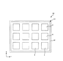
図1は、本発明の表示装置の第1実施形態を示す断面図、図2は、図1に示す表示装置の平面図(上面図)、図3は、図1に示す表示装置の駆動を説明する断面図である。なお、以下では、説明の都合上、図1、3中の上側を「上」、下側を「下」として説明を行う。また、図1に示すように、表示装置の平面視にて互いに直交する2方向を「X方向」および「Y方向」とする。 1 is a cross-sectional view showing a first embodiment of the display device of the present invention, FIG. 2 is a plan view (top view) of the display device shown in FIG. 1, and FIG. 3 is a drive of the display device shown in FIG. It is sectional drawing demonstrated. In the following description, for convenience of explanation, the upper side in FIGS. 1 and 3 is described as “upper” and the lower side is described as “lower”. Further, as shown in FIG. 1, two directions orthogonal to each other in a plan view of the display device are referred to as “X direction” and “Y direction”.
図1に示す表示装置(本発明の表示装置)20は、粒子の泳動を利用して所望の画像を表示する電気泳動表示装置である。この表示装置20は、表示シート(フロントプレーン)21と、回路基板(バックプレーン)22とを有している。なお、表示シート21および回路基板22が表示シートを構成しているともいえる。
図1に示すように、表示シート21は、平板状の基部1と基部1の下面に設けられた第1の電極3とを備える基板(電極基板)11と、基板11の下方に設けられ、電気泳動粒子70を含む分散液100(電気泳動分散液)が充填された表示層400とを有している。このような表示シート21では、基板11の上面が表示面111を構成している。
A display device 20 (display device of the present invention) shown in FIG. 1 is an electrophoretic display device that displays a desired image using particle migration. The
As shown in FIG. 1, the
一方、回路基板22は、平板状の基部2と基部2の上面に設けられた複数の第2の電極4とを備える基板12と、この基板12に設けられた図示しない電気回路とを有している。
この電気回路は、例えば、マトリックス状に配列されたTFT(スイッチング素子)と、TFTに対応して形成されたゲート線およびデータ線と、ゲート線に所望の電圧を印加するゲートドライバーと、データ線に所望の電圧を印加するデータドライバーと、ゲートドライバーとデータドライバーの駆動を制御する制御部と、を有している。
On the other hand, the
This electric circuit includes, for example, TFTs (switching elements) arranged in a matrix, gate lines and data lines formed corresponding to the TFTs, a gate driver that applies a desired voltage to the gate lines, and data lines A data driver for applying a desired voltage to the gate driver, and a gate driver and a controller for controlling the driving of the data driver.
以下、各部の構成について順次説明する。
(基板)
基部1および基部2は、それぞれ、シート状(平板状)の部材で構成され、これらの間に配置される各部材を支持および保護する機能を有する。各基部1、2は、それぞれ可撓性を有するもの、硬質なもののいずれであってもよいが、可撓性を有するものであるのが好ましい。可撓性を有する基部1、2を用いることにより、可撓性を有する表示装置20、すなわち、例えば電子ペーパーを構築する上で有用な表示装置20を得ることができる。
Hereinafter, the structure of each part is demonstrated sequentially.
(substrate)
The
基部1、2が可撓性を有するものである場合、その構成材料としては、透明性の高いガラスまたは樹脂が挙げられる。前記樹脂としては、PET(ポリエチレンテレフタレート)、PEN(ポリエチレンナフタレート)等のポリエステル、ポリエチレン等のポリオレフィン、変性ポリオレフィン、環状オレフィン(COP)、ポリアミド、熱可塑性ポリイミド、ポリエーテル、ポリエーテルエーテルケトン、ポリカーボネート(PC)、ポリウレタン系、塩素化ポリエチレン系等の各種熱可塑性エラストマー等、またはこれらを主とする共重合体、ブレンド体、ポリマーアロイ等が挙げられ、これらのうちの1種または2種以上を混合して用いることができる。
In the case where the
基部1、2の平均厚さは、それぞれ構成材料、用途等により適宜設定され、特に限定されないが、可撓性を有するものとする場合、20μm以上500μm以下程度であるのが好ましく、25μm以上250μm以下程度であるのがより好ましく、50μm以上200μm以下程度であるのがさらに好ましい。これにより、表示装置20の柔軟性と強度との調和を図りつつ、表示装置20の小型化(特に薄型化)を図ることができる。
The average thicknesses of the
これらの基部1、2の表示層400側の面、すなわち、基部1の下面および基部2の上面に、それぞれ膜状をなす第1の電極3および第2の電極4が設けられている。本実施形態では、第1の電極3が共通電極とされ、第2の電極4が、X方向およびY方向に千鳥状に分割された個別電極(TFTに接続された画素電極)とされている。表示装置20では、1つの第2の電極4と第1の電極3とが重なり合う領域が1つの画素を構成している。
A film-like
電極3、4の構成材料としては、それぞれ、実質的に導電性を有するものであれば特に限定されず、例えば、金、銀、銅、アルミニウムまたはこれらを含む合金等の金属材料、カーボンブラック、グラフェン、カーボンナノチューブ、フラーレン等の炭素系材料、ポリアセチレン、ポリフルオレン、ポリチオフェンまたはこれらの誘導体等の導電性高分子材料、ポリビニルアルコール、ポリカーボネート等のマトリックス樹脂中に、NaCl、Cu(CF3SO3)2等のイオン性物質を分散させたイオン導電性高分子材料、インジウム酸化物(IO)、インジウムスズ酸化物(ITO)、フッ素ドープ酸化スズ(FTO)、酸化亜鉛(ZnO)等の導電性酸化物材料のような各種導電性材料が挙げられ、これらのうちの1種または2種以上を組み合わせて用いることができる。
The constituent materials of the
また、電極3、4の平均厚さは、それぞれ、構成材料、用途等により適宜設定され、特に限定されないが、0.01μm以上10μm以下程度であるのが好ましく、0.02μm以上5μm以下程度であるのがより好ましい。
ここで、各基部1、2および各電極3、4のうち、表示面111側に配置される基部および電極は、それぞれ光透過性を有するもの、すなわち、実質的に透明(無色透明、有色透明または半透明)とされる。本実施形態では、基板11の上面が表示面111を構成するため、少なくとも基部1および第1の電極3は、実質的に透明とされる。これにより、表示装置20に表示された画像を表示面111側から目視により容易に認識することができる。
Further, the average thickness of the
Here, among the
(封止部)
基板11と基板12との間には、それらの縁部に沿って封止部(シール部)5が設けられている。この封止部5により、表示層400が気密的に封止されている。その結果、表示装置20内への水分の浸入を防止して、表示装置20の表示性能の劣化をより確実に防止することができる。
(Sealing part)
Between the board |
封止部5の構成材料としては、特に限定されず、例えば、アクリル系樹脂、ウレタン系樹脂、オレフィン系樹脂のような熱可塑性樹脂、エポキシ系樹脂、メラミン系樹脂、フェノール系樹脂、シリコーン系樹脂のような熱硬化性樹脂等の各種樹脂材料等が挙げられ、これらのうちの1種または2種以上を組み合わせて用いることができる。
また、封止部5の高さは、特に限定されないが、5μm以上100μm以下程度であるのが好ましい。
The constituent material of the sealing
Further, the height of the sealing
(壁部)
図1に示すように、表示層400は、その外縁を囲うように設けられた壁部(隔壁)91と、基板11、基板12および壁部91で画成された空間(分散液封入空間)101と、空間101内に充填された分散液100(電気泳動分散液)と、を有している。
壁部91の表面には、必要に応じて、炭化フッ素プラズマ処理等の各種撥水処理が施されていてもよい。これにより、後述するように、表示装置20の製造がより簡単となり、より優れた表示特性および信頼性を発揮することができる表示装置20を得ることができる。
(Wall)
As shown in FIG. 1, the
The surface of the
壁部91の構成材料としては、特に限定されず、例えば、エポキシ樹脂、アクリル樹脂、フェノール樹脂、ユリア樹脂、メラミン樹脂、ポリエステル(不飽和ポリエステル)、ポリイミド、シリコーン樹脂、ウレタン樹脂等の各種熱可塑性樹脂または熱硬化性樹脂が挙げられ、これらのうちの1種または2種以上を混合して用いることができる。
壁部91の高さは、特に限定されないが、5μm以上100μm以下程度であるのが好ましい。壁部91の高さを前記範囲内にすることにより、電界に応じて電気泳動粒子70が短時間で移動可能になるとともに、非表示状態において電気泳動粒子70が透けて見えるのを防止することができる。
The constituent material of the
Although the height of the
また、壁部91の平均幅は、壁部91に要求される機械的強度等を考慮して適宜設定されるが、1μm以上10μm以下程度であるのが好ましい。そして、壁部91のアスペクト比(平均高さ/平均幅)は、1〜50程度であるのが好ましい。
なお、本実施形態では、壁部91の横断面形状が、幅が基板12から基板11側へ向けて漸減する逆テーパー状をなしているが、かかる形状に限定されず、例えば矩形(長方形)であってもよい。
また、壁部91の横断面形状は、全体にわたって一定でなくてもよく、一部異なる形状であってもよい。この場合、この箇所では空間101の気密性が低下するため、仮に空間101に気泡が混入したとしても、その気泡を外部に排出することができる。
Further, the average width of the
In the present embodiment, the cross-sectional shape of the
Moreover, the cross-sectional shape of the
(分散液)
分散液100(電気泳動分散液)は、分散媒7と、分散媒7中に分散された電気泳動粒子70と、を含んでいる。
電気泳動粒子70は、正または負に帯電し、分散媒7が呈する色と異なる色を呈している。
(Dispersion)
The dispersion liquid 100 (electrophoretic dispersion liquid) includes the
The
電気泳動粒子70が呈する色は、分散媒7が呈する色と異なる色であれば特に限定されないが、例えば分散媒7が呈する色が淡色または白色である場合には、濃色または黒色であるのが好ましく、反対に、分散媒7が呈する色が濃色または黒色である場合には、淡色または白色であるのが好ましい。これにより、電気泳動粒子70と分散媒7とで明度差が大きくなるため、例えば電気泳動粒子70が局所的に集合した場合、その領域とそれに隣接する領域(分散媒7で占められている領域)との明度差も大きくなるため、電気泳動粒子70の集合領域を制御することによってコントラストの高い表示が可能になる。なお、電気泳動粒子70については、後に詳述する。
The color exhibited by the
分散媒7としては、沸点が100℃以上に高く比較的高い絶縁性を有するものが好ましく用いられる。かかる分散媒7としては、例えば、各種水(例えば、蒸留水、純水等)、ブタノールやグリセリン等のアルコール類、ブチルセロソルブ等のセロソルブ類、酢酸ブチル等のエステル類、ジブチルケトン等のケトン類、ペンタン等の脂肪族炭化水素類(流動パラフィン)、シクロヘキサン等の脂環式炭化水素類、キシレン等の芳香族炭化水素類、塩化メチレン等のハロゲン化炭化水素類、ピリジン等の芳香族複素環類、アセトニトリル等のニトリル類、N,N−ジメチルホルムアミド等のアミド類、カルボン酸塩、シリコーンオイルまたはその他の各種油類等が挙げられ、これらを単独または混合物として用いることができる。
As the
中でも、分散媒7としては、脂肪族炭化水素類(流動パラフィン)またはシリコーンオイルを主成分とするものが好ましい。流動パラフィンまたはシリコーンオイルを主成分とする分散媒7は、電気泳動粒子70の凝集抑制効果が高いことから、表示装置20の表示性能が経時的に劣化するのを抑制することができる。また、流動パラフィンまたはシリコーンオイルは、不飽和結合を有しないため耐候性に優れ、さらに安全性も高いという利点を有している。
Among these, as the
また、分散媒7としては、比誘電率が1.5以上3以下であるものが好ましく用いられ、1.7以上2.8以下であるものがより好ましく用いられる。このような分散媒7は、後述するシロキサン系化合物72を含む電気泳動粒子70の分散性に優れるとともに、電気絶縁性も良好である。このため、消費電力が小さく、コントラストの高い表示が可能な表示装置20の実現に寄与する。なお、この誘電率の値は、50Hzにおいて測定された値であり、かつ、含有する水分量が50ppm以下、温度25℃である分散媒7について測定された値である。
Moreover, as the
以上、表示装置20の構成について説明したが、このような表示装置20は、例えば次のようにして駆動する。なお、以下の説明では、図1に示す複数の第2の電極4のうち、1つに対して電圧を印加した場合について説明する。また、以下の説明においては、電気泳動粒子70が正に帯電しているものとする。
第1の電極3と第2の電極4との間に、第2の電極4が負電位となる電圧を印加すると、当該電圧印加により発生した電界が表示層400中の電気泳動粒子70に作用する。すると、電気泳動粒子70が第2の電極4側に泳動して集まる。これにより、図3(a)に示すように、表示面111には主に分散媒7が呈する色が表示される。
While the configuration of the
When a voltage at which the
一方、第2の電極4が正電位となる電圧を印加すると、当該電圧印加により発生した電界が表示層400中の電気泳動粒子70に作用する。すると、電気泳動粒子70が第1の電極3側に泳動して集まる。これにより、図3(b)に示すように、表示面111には主に電気泳動粒子70が呈する色が表示される。
以上のような電気泳動粒子70の駆動を画素ごと(第2の電極4ごと)に行うことにより、表示面111には所望の画像を表示することができる。
On the other hand, when a voltage at which the
By driving the
このように、表示装置20では、電界の向きに応じて電気泳動粒子70を泳動させ、それによって生じる色度や明度の差により画像表示を行う。この際、良好な画像表示を行うためには、複数の電気泳動粒子70が分散媒7中において互いに凝集することなく安定的に存在するとともに、電界が発生したときには速やかに泳動することが必要となる。すなわち、電気泳動粒子70には、分散媒7中における分散性(以下、単に「分散性」ともいう)と帯電特性との両立が求められている。
As described above, in the
((電気泳動粒子))
以下、分散液100に含まれる電気泳動粒子70について詳述する。
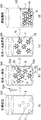
図4は、図1に示す表示装置に用いられる電気泳動粒子を模式的に示す断面図、図5は、図4に示す電気泳動粒子の粒子表面に結合したシロキサン系化合物を説明するための図である。また、図6は、図5に示す構造Zを有するシロキサン系化合物を得るのに用いるカップリング剤および変性シリコーンオイルについて、カップリング剤に含まれる反応性官能基X、および、変性シリコーンオイルに含まれる反応性官能基Yの具体例を示す図である。
((Electrophoretic particles))
Hereinafter, the
4 is a cross-sectional view schematically showing the electrophoretic particles used in the display device shown in FIG. 1, and FIG. 5 is a diagram for explaining a siloxane compound bonded to the particle surface of the electrophoretic particles shown in FIG. It is. FIG. 6 shows a coupling agent and a modified silicone oil used to obtain the siloxane compound having the structure Z shown in FIG. 5. The reactive functional group X contained in the coupling agent and the modified silicone oil include It is a figure which shows the specific example of the reactive functional group Y.
図4に示すように、電気泳動粒子70は、コア粒子71(粒子)と、コア粒子71の表面に結合されたシロキサン系化合物72と、を有する。
このような電気泳動粒子70は、シロキサン系化合物72により、別の電気泳動粒子70との著しい接近が阻害されるため、分散媒7中における適度な分散性が付与される。また、シロキサン系化合物72は、非極性または低極性の分散媒7に対する親和性が高いことから、分散媒7中における電気泳動粒子70の分散性を高めることができる。また、シロキサン系化合物72が分散媒7中における電気泳動粒子70の分散性を高める効果が高いため、コア粒子71の表面がシロキサン系化合物72によって被覆される面積を小さくすることができる。言い換えると、コア粒子71の表面におけるシロキサン系化合物72が結合しない領域の面積を大きくすることができる。そのため、その領域において、コア粒子71自体が有する帯電性を十分に生かしたり、その領域に帯電性を有する基を導入したりして、電気泳動粒子70の帯電性を高めることができる。
As shown in FIG. 4, the
Such
このようなことから、電気泳動粒子70は、分散媒7中において優れた分散性および帯電性を発揮することができる。したがって、シロキサン系化合物72によって生じる一定の斥力によって電気泳動粒子70同士の凝集が抑えられ、それによって電気泳動粒子70の泳動抵抗が減少するとともに、コア粒子71自体が有する帯電性や分極基によって電気泳動粒子70には一定のクーロン力が発生するため、結果的に、より弱い電界下でも十分な電気泳動が可能になる。その結果、少ない消費電力で応答性の高い画像表示を得ることができる。
For this reason, the
また、前述したようにシロキサン系化合物72により電気泳動粒子70の分散性が高められるため、分散媒7に分散剤を全く添加しなくても済む。このため、分散剤を多量に添加した場合に生じる、第1の電極3と第2の電極4との間の絶縁性の低下を防止することができる。これにより、電圧印加時のリーク電流の発生が抑制され、表示装置20の消費電力の低減を図ることができる。
Further, since the dispersibility of the
なお、分散媒7中には、分散剤が添加されていてもよく、その場合、分散媒7中に添加される分散剤の添加量を少なくすることができ、第1の電極3と第2の電極4との間の絶縁性の抑制することができる。かかる分散剤としては、例えば、ポリアミドアミンとその塩、塩基性官能基変性ポリウレタン、塩基性官能基変性ポリエステル、塩基性官能基変性ポリ(メタ)アクリレート、ポリオキシエチレンアルキルアミン、アルカノールアミン、ポリアクリルアミド等が挙げられ、これらのうちの1種または2種以上の混合物が用いられる。
分散剤の添加量は、分散媒7の0.3wt%以下であるのが好ましく、0.1wt%以下であるのがより好ましい。分散剤の添加量を前記範囲内に抑えることで、分散剤を添加したとしても、第1の電極3と第2の電極4との間の絶縁性の低下を最小限に抑えることができる。
Note that a dispersant may be added to the
The addition amount of the dispersant is preferably 0.3 wt% or less of the
以下、電気泳動粒子70を構成する各部を順次詳細に説明する。
まず、コア粒子71について説明する。
コア粒子71としては、特に限定されないが、例えば、酸化チタン、酸化亜鉛、酸化鉄、酸化クロム、酸化ジルコニウム等の酸化物系粒子や、窒化ケイ素、窒化チタン等の窒化物系粒子、硫化亜鉛等の硫化物系粒子、硼化チタン等の硼化物系粒子、クロム酸ストロンチウム、アルミン酸コバルト、亜クロム銅、ウルトラマリン等の無機顔料粒子、アゾ系、キナクリドン系、アントラキノン系、ジオキサジン系、ペリレン系等の有機顔料粒子等を用いることができる。また、アクリル系樹脂、ウレタン系樹脂、尿素系樹脂、エポキシ系樹脂、ポリスチレン、ポリエステル等で構成された樹脂粒子の表面に顔料を塗布した複合粒子を用いることもできる。
Hereinafter, each part which comprises the
First, the
The
また、コア粒子71としては、後述するようにカップリング剤を用いる場合において、カップリング剤との反応性を考慮すると、表面に水酸基が存在するものが好ましく、この点から、無機材料を用いることがより好ましい。
また、コア粒子71の平均粒子径は、特に限定されないが、好ましくは10nm以上800nm以下、より好ましくは20nm以上400nm以下である。コア粒子71の平均粒子径を前記範囲内に設定することにより、電気泳動粒子70による十分な色度の表示と電気泳動粒子70の速やかな電気泳動とを両立することができる。その結果、高コントラストの表示と高い応答速度とを両立することができる。
Further, as the
The average particle diameter of the
また、コア粒子71の平均粒子径を前記範囲内に設定することにより、電気泳動粒子70の沈降や泳動速度のバラツキを抑え、表示ムラや表示不良の発生を抑制することができる。
なお、コア粒子71の平均粒子径は、動的光散乱式粒度分布測定装置(例えば、製品名:LB−500、(株)堀場製作所製)で測定した体積平均粒子径を意味する。
In addition, by setting the average particle diameter of the
In addition, the average particle diameter of the
また、本実施形態では、分散液100中にコア粒子71が1種類含まれている場合について説明したが、複数種のコア粒子71が含まれていてもよい。この場合、例えば、白色と黒色、あるいは、淡色と濃色、といった明度や色度が大きく異なる組み合わせで複数種のコア粒子71を選択することで、よりコントラストに優れた表示が可能になる。また、異なる複数種のコア粒子71を用いる場合、異なる複数種のコア粒子71間で、シロキサン系化合物72の種類や導入量等が同じであってもよいし異なっていてもよい。
In the present embodiment, the case where one type of
次に、シロキサン系化合物72について説明する。
シロキサン系化合物72は、複数のシロキサン結合が直列に連結されている連結構造(以下、「シリコーン主鎖」ともいう)を含む化合物(高分子鎖を含む化合物)であればいかなる化合物であってもよいが、好ましくは前記連結構造を含む主鎖と、この主鎖に結合している側鎖とで構成されている直鎖状の分子構造を有する化合物とされる。このような化合物であれば、シロキサン系化合物72の長鎖の分子構造が比較的安定に維持されることとなり、シロキサン系化合物72を隔ててコア粒子71同士の離間距離を十分にとることができるので、電気泳動粒子70に分散性を付与するというシロキサン系化合物72の機能がより一層促進されることとなる。
Next, the
The siloxane-based
また、分散媒7には、比較的極性が低いもの(非極性または低極性)が多く用いられる。一方、シロキサン結合を含む化合物も、側鎖の構造にもよるが、比較的極性が低いものが多い。したがって、このようなシロキサン系化合物72を含む電気泳動粒子70は、分散媒7に対して特に良好な分散性を示す。
また、シロキサン系化合物72は、シリコーン主鎖を有するシリコーンオイルまたはその変性物に由来する構造(以下、単に「シリコーンオイル由来の構造」ともいう)を含んでいるのが好ましい。シリコーンオイルまたはその変性物は、分散媒7としても用いられることが多いので、これに由来する構造をシロキサン系化合物72が含んでいることにより、電気泳動粒子70の分散性が特に高くなる。
このようなシリコーンオイル由来の構造は、図5(a)に示すように、コア粒子71の表面に直接連結していてもよいし、図5(b)に示すように、コア粒子71の表面にカップリング剤由来の構造を介して連結していてもよい。
Further, as the
The
Such a structure derived from silicone oil may be directly connected to the surface of the
より具体的に説明すると、図5(a)に示す例のシロキサン系化合物72は、シリコーンオイル由来の官能基とコア粒子71の表面の水酸基とを反応させて得られる。この例のシロキサン系化合物72は、シリコーンオイル由来の構造のみで構成され、シロキサン結合で構成されている主鎖(シリコーン主鎖)の末端に結合している炭化水素構造がコア粒子71に連結されている。したがって、シロキサン系化合物72の大部分がシロキサン結合で占められることになるため、例えば分散媒7としてシリコーンオイルまたはその変性物が用いられたときに、電気泳動粒子70の分散性が特に高くなる。
More specifically, the
一方、図5(b)に示す例のシロキサン系化合物72は、変性シリコーンオイルとカップリング剤とを反応させ、得られた反応物のうち、カップリング剤由来の加水分解性基とコア粒子71の表面の水酸基との間で脱水縮合反応させて得られる。この例のシロキサン系化合物72は、シリコーンオイル由来の構造とカップリング剤由来の構造とで構成され、カップリング剤由来の構造721を介して、シリコーンオイル由来の構造722がコア粒子71に連結されている。このような構造のシロキサン系化合物72は、長鎖で直鎖状の分子構造を含んでいるにも関わらず、コア粒子71に対する結合量の制御が容易であり、その結果、目的とする量に厳密に制御されたシロキサン系化合物72を含む電気泳動粒子70を実現することができる点で有用である。換言すれば、長鎖で直鎖状の分子構造を含むシロキサン系化合物72は、目的とする量をコア粒子71に対して正確に導入することは多くの困難を伴うのに対し、シリコーンオイル由来の構造722とコア粒子71との間をカップリング剤由来の構造721で仲立ちさせることにより、あらかじめ変性シリコーンオイルとカップリング剤との反応機会を十分に確保するというプロセスを経ることができる。このため、コア粒子71に対するカップリング剤の反応性の高さを効果的に活かすことができ、結果的にシロキサン系化合物72の導入量を正確に制御することができる。
On the other hand, the
シロキサン系化合物72の重量平均分子量は、1000以上10万以下程度であるのが好ましく、10000以上60000以下程度であるのがより好ましい。かかる重量平均分子量を前記範囲内に設定することで、シロキサン系化合物72の分子構造の長さが最適化され、コア粒子71の表面に、コア粒子71自体の帯電性を発揮したり分極基を導入したりし得る領域を十分に確保しつつ、長鎖で直鎖状の構造に由来する分散性が十分に付与された電気泳動粒子70が得られる。
The weight average molecular weight of the
なお、シロキサン系化合物72の重量平均分子量は、ゲル浸透クロマトグラフィー(GPC)を用いて測定された、ポリスチレン換算重量平均分子量のことである。
また、図5(a)および図5(b)中におけるnは、それぞれ上述した重量平均分子量と同様の理由から、12以上1400以下程度であるのが好ましく、130以上800以下程度であるのがより好ましい。
また、図5(b)における構造Zは、カップリング剤に含まれる反応性官能基Xとシリコーンオイルに含まれる反応性官能基Yとが反応してなる構造である。
In addition, the weight average molecular weight of the
Further, n in FIGS. 5 (a) and 5 (b) is preferably about 12 or more and 1400 or less, and preferably about 130 or more and 800 or less for the same reason as the above-described weight average molecular weight. More preferred.
Moreover, the structure Z in FIG.5 (b) is a structure where the reactive functional group X contained in a coupling agent and the reactive functional group Y contained in silicone oil react.
反応性官能基X、Yとしては、例えば、図6に示すものが挙げられる。なお、図6中のRは、アルキル基のような脂肪族炭化水素基である。
なお、シロキサン系化合物72の末端および側鎖は、極性の低い置換基で構成されていることが好ましい。これにより、電気泳動粒子70の分散性をより高めることができる。具体的な置換基としては、例えばアルキル基等が挙げられる。
Examples of the reactive functional groups X and Y include those shown in FIG. In addition, R in FIG. 6 is an aliphatic hydrocarbon group such as an alkyl group.
In addition, it is preferable that the terminal and side chain of the
また、コア粒子71の表面におけるシロキサン系化合物72が結合している領域の占有率(被覆率)は、0.05%以上20%以下であるのが好ましく、0.1%以上10%以下であるのがより好ましく、0.2%以上5%以下であるのがさらに好ましい。かかる領域の占有率を前記範囲内に設定することにより、主にシロキサン系化合物72に起因する分散性と、主にコア粒子71の表面またはその表面に導入された基に起因する帯電特性と、の両立をより強化することができる。すなわち、例えば分散液100が置かれる温度が大きく変化するような環境下、あるいは、電界の強さが小さい環境下においても、分散性と帯電特性との両立を図ることができる。
The occupation ratio (coverage) of the region where the
なお、かかる領域の占有率が前記下限値を下回る場合は、分散性が低下し、分散液100が置かれる環境によっては電気泳動粒子70が凝集してしまうおそれがある。一方、かかる領域の占有率が前記上限値を上回る場合は、電気泳動粒子70の製造方法の種類によっては、コア粒子71自体の帯電特性を発揮させたりコア粒子71の表面に他の基を導入したりすることが難しくなる。
In addition, when the occupation rate of this area | region is less than the said lower limit, dispersibility falls and there exists a possibility that the
ここで、コア粒子71の表面におけるシロキサン系化合物72が結合している領域の占有率(被覆率)[%]は、コア粒子71の表面に結合したシロキサン系化合物72の分子1つあたりが占める面積を「単位面積」とし、コア粒子71の表面に結合したシロキサン系化合物72の分子の数を「分子数」としたとき、下記式により求められる。
占有率(被覆率)=(単位面積×分子数)/(コア粒子の表面積)×100
ここで、「単位面積」は、シロキサン系化合物72の分子構造から計算により求めることができる。
Here, the occupation ratio (coverage) [%] of the region where the
Occupancy (coverage) = (unit area × number of molecules) / (surface area of core particle) × 100
Here, the “unit area” can be obtained from the molecular structure of the
また、「分子数」は、コア粒子1つ当たりに結合したシロキサン系化合物72の質量[g]と、シロキサン系化合物72の分子量[g/mol]と、1モルあたりの分子数6.02×1023[個/mol]とから計算により求めることができる。
以上説明したような電気泳動粒子70を含む分散液100によれば、優れた電気泳動粒子70の分散性を実現しつつ、導電性を低くすることができる。
また、このような分散液100を用いた表示シート21および表示装置20によれば、コントラストの高い表示が可能である。
The “number of molecules” includes the mass [g] of the
According to the
Further, according to the
<第2実施形態>
次に、本発明の表示装置の第2実施形態について説明する。
図7は、本発明の表示装置の第2実施形態を示す断面図である。なお、以下の説明では、説明の都合上、図7の上側を「上」、下側を「下」として説明を行う。
以下、第2実施形態について説明するが、以下の説明では第1実施形態との相違点を中心に説明し、同様の事項についてはその説明を省略する。なお、前述した第1実施形態と同様の構成には、同一符号を付してある。
Second Embodiment
Next, a second embodiment of the display device of the present invention will be described.
FIG. 7 is a cross-sectional view showing a second embodiment of the display device of the present invention. In the following description, for convenience of explanation, the upper side in FIG. 7 is described as “upper” and the lower side is described as “lower”.
Hereinafter, although 2nd Embodiment is described, in the following description, it demonstrates centering around difference with 1st Embodiment, The description is abbreviate | omitted about the same matter. In addition, the same code | symbol is attached | subjected to the structure similar to 1st Embodiment mentioned above.
第2実施形態に係る表示装置20は、壁部91の内側の空間101をさらに複数の区画に区分けする壁部92を備える以外、第1実施形態に係る表示装置20と同様である。
すなわち、表示層400には、複数の壁部92がY方向に所定の間隔を隔てて設けられている。また、図示しないものの、表示層400には、複数の壁部がX方向にも所定の間隔を隔てて設けられている。これにより、空間101には格子状に区分された画素区画が形成される。
The
That is, the
各画素区画には、それぞれ第2の電極4が対応して配置されている。このため、第2の電極4に印加される電圧を適宜制御することにより、各画素区画が発する色を制御し、表示面111から視認される画像を自在に生成することができる。
このような壁部92は、前述した壁部91と同様の構造を有するものとされるが、平均幅については壁部91より小さくてもよい。これにより、画素の開口率を高めることができる。
このような第2実施形態によっても、第1実施形態と同様の作用、効果が得られる。
In each pixel section, a
Such a
Also by such 2nd Embodiment, the effect | action and effect similar to 1st Embodiment are acquired.
<第3実施形態>
次に、本発明の表示装置の第3実施形態について説明する。
図8は、本発明の表示装置の第3実施形態を示す断面図である。なお、以下の説明では、説明の都合上、図8の上側を「上」、下側を「下」として説明を行う。
以下、第3実施形態について説明するが、以下の説明では第1、第2実施形態との相違点を中心に説明し、同様の事項についてはその説明を省略する。なお、前述した第1実施形態と同様の構成には、同一符号を付してある。
<Third Embodiment>
Next, a third embodiment of the display device of the present invention will be described.
FIG. 8 is a cross-sectional view showing a third embodiment of the display device of the present invention. In the following description, for convenience of explanation, the upper side in FIG. 8 is described as “upper” and the lower side is described as “lower”.
Hereinafter, the third embodiment will be described. In the following description, differences from the first and second embodiments will be mainly described, and description of similar matters will be omitted. In addition, the same code | symbol is attached | subjected to the structure similar to 1st Embodiment mentioned above.
本実施形態に係る表示装置20は、分散液100がカプセル本体(殻体)401内に封入されてなるマイクロカプセル40を備えていること以外は、第1実施形態と同様である。
すなわち、本実施形態に係る表示装置20は、分散液100をカプセル本体401内に封入してなる複数のマイクロカプセル40が、バインダー41で空間101内に固定(保持)されることによって構成されている。
マイクロカプセル40は、各基板11、12間に、単層で(厚さ方向に重なることなく1個ずつ)、かつX方向およびY方向に拡がるよう並べられている。
The
That is, the
The
カプセル本体(殻体)401の構成材料としては、例えば、ゼラチン、アラビアゴムとゼラチンとの複合材料、ウレタン系樹脂、メラミン系樹脂、尿素樹脂、エポキシ系樹脂、フェノール系樹脂、アクリル系樹脂、ウレタン系樹脂、オレフィン系樹脂、ポリアミド、ポリエーテルのような各種樹脂材料が挙げられ、これらのうち1種または2種以上を組み合わせて用いることができる。 Examples of the constituent material of the capsule body (shell) 401 include gelatin, a composite material of gum arabic and gelatin, a urethane resin, a melamine resin, a urea resin, an epoxy resin, a phenol resin, an acrylic resin, and urethane. Various resin materials such as resin, olefin resin, polyamide, and polyether can be used, and one or more of these can be used in combination.
また、カプセル本体401は、複数の層の積層体で構成されていてもよい。この場合、最内層の構成材料としては、メラミン系樹脂、尿素樹脂のようなアミノ樹脂、またはこれらの複合樹脂等が好ましく用いられる。一方、最外層の構成材料としては、エポキシ系樹脂が好ましく用いられる。
また、カプセル本体401の構成材料においては、架橋剤により架橋(立体架橋)を形成するようにしてもよい。これにより、カプセル本体401の柔軟性を維持しつつ、強度を向上させることができる。その結果、マイクロカプセル40が容易に崩壊するのを防止することができる。
このようなマイクロカプセル40は、その大きさがほぼ均一であることが好ましい。これにより、表示装置20では、表示ムラの発生が防止または低減され、より優れた表示性能を発揮することができる。
Moreover, the capsule
Moreover, in the constituent material of the capsule
また、マイクロカプセル40は、球状をなして存在しているのが好ましい。これにより、マイクロカプセル40は、耐圧性および耐ブリード性に優れたものとなる。したがって、このように表示装置20を作動させているとき、もしくは、表示装置20を保存している間に、表示装置20に衝撃が加わったり、表示面111が押圧されたりした場合でも、マイクロカプセル40の破壊や分散液100の散逸が防止され、長期間安定に動作することができる。
The
なお、マイクロカプセル40の平均粒径は、5μm以上50μm以下程度であるのが好ましく、10μm以上30μm以下程度であるのがより好ましい。マイクロカプセル40の平均粒径を前記範囲とすることにより、表示装置20において電気泳動粒子70の電気泳動をより確実に制御することができるようになる。すなわち、電気泳動粒子70にパルス状の電界を作用させたとしても、マイクロカプセル40内の端部にまで確実に電気泳動させることができる。その結果、表示のコントラストを高めることができる。
The average particle diameter of the
バインダー41は、例えば、基板11と基板12とを接合する目的、基板11と基板12との間にマイクロカプセル40を固定する目的、第1の電極3と第2の電極4との間の絶縁性を確保する目的等により供給される。これにより、表示装置20の耐久性および信頼性をより向上させることができる。
このバインダー41には、基板11、基板12、およびカプセル本体401(マイクロカプセル40)との親和性(密着性)に優れ、かつ、絶縁性に優れる樹脂材料(絶縁性または微小電流のみが流れる樹脂材料)が好適に使用される。
The
The
このようなバインダー41としては、例えば、ポリエチレン、ポリプロピレン、ABS樹脂、メタクリル酸エステル樹脂、メタクリル酸メチル樹脂、塩化ビニル樹脂、セルロース系樹脂等の熱可塑性樹脂、シリコーン系樹脂、ウレタン系樹脂等の各種樹脂材料が挙げられ、これらのうちの1種または2種以上を組み合わせて用いることができる。
以上のような本実施形態に係る表示装置20は、前述した第1実施形態および第2実施形態と同様の作用、効果を奏する。
Examples of such a
The
≪電気泳動分散液の製造方法≫
次に、本発明の電気泳動分散液の製造方法について説明する。なお、以下では、前述した分散液100を製造する場合を例に説明する。
<電気泳動分散液の製造方法の第1実施形態>
まず、本発明の電気泳動分散液の製造方法の第1実施形態を説明する。
≪Method for producing electrophoresis dispersion≫
Next, a method for producing the electrophoretic dispersion of the present invention will be described. Hereinafter, a case where the above-described
<First Embodiment of Manufacturing Method of Electrophoretic Dispersion>
First, a first embodiment of the method for producing an electrophoretic dispersion of the present invention will be described.
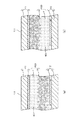
図9は、本発明の電気泳動分散液の製造方法の第1実施形態を説明するための図、図10は、粒子の表面に結合させるシロキサン系化合物の前駆体の製造方法の例を説明するための図である。
図9に示す分散液100の製造方法は、[1]分散媒7中で、シロキサン系化合物72をコア粒子71の表面に結合させる結合工程と、[2]コア粒子71に結合していないシロキサン系化合物の前駆体72Aを除去する除去工程と、を有する。
FIG. 9 is a diagram for explaining the first embodiment of the method for producing an electrophoretic dispersion of the present invention, and FIG. 10 is a diagram for explaining an example of a method for producing a precursor of a siloxane compound to be bonded to the particle surface. FIG.
The manufacturing method of the
以下、各工程を順次詳細に説明する。
[1]結合工程
1−1
まず、図9(a)に示すように、容器300内で、分散媒7にコア粒子71を分散させる。
Hereinafter, each process will be described in detail.
[1] Joining process 1-1
First, as shown in FIG. 9A, the
この分散媒7は、後述する工程1−2において反応溶媒として用いられる液性媒体として機能する。
この液性媒体が分散媒7であることにより、液性媒体を最終的な分散媒7に置換することが不要となり、最終的に得られる分散液100の分散媒7に不本意な液体が混入するのを比較的簡単に防止または抑制することができる。また、液性媒体を最終的な分散媒7に置換することが不要となるため、後述する除去工程[2]を簡単化することができる。
This
Since this liquid medium is the
本実施形態では、分散媒7の粘度(25℃における動粘度)は、コア粒子71の種類やシロキサン系化合物72の種類等に応じて決められるものであり、特に限定されないが、0.5mm2/s以上20mm2/s以下であることが好ましい。これにより、最終的に得られる分散液100における電気泳動粒子70の応答性を優れたものとしつつ、シロキサン系化合物72と結合していなくてもコア粒子71の分散媒7に対する分散性を高めることができる。
In the present embodiment, the viscosity of the dispersion medium 7 (kinematic viscosity at 25 ° C.) is determined according to the type of the
また、液性媒体には、分散媒7の他に、他の溶媒が含まれていてもよく、例えば、液性媒体が二相系溶媒であってもよい。液性媒体が分散媒7の一相系溶媒であるか、二相系溶媒であるかはコア粒子71の種類や粒子表面に結合させる修飾剤(高分子鎖を含む化合物)の種類に応じて選択すればよい。例えば、コア粒子の表面に結合させる修飾剤のポリスチレン換算の数平均分子量が40,000未満の場合や、粘度が2,000mm2/s未満の場合は液性媒体が分散媒7の一相系溶媒であることが好ましい。また、修飾剤の分子量が40,000以上の場合や、粘度が2,000mm2/s以上の場合には液性媒体全体の重量に対して微量の極性溶媒を添加することが好ましい。添加する極性溶媒としては水が好ましく、添加する極性溶媒の液性媒体全体に占める含有量としては0.01wt%以上0.1wt%以下が好ましく、0.02wt%以上0.1wt%以下がより好ましい。これにより、最終的に得られる分散液100の分散媒7中に不要な液体が混入するのを防止し、分散液100の特性を優れたものとすることができる。また、添加する水(極性溶媒)の量が多すぎると、修飾剤同士で反応してしまい、コア粒子71の分散性が低下する場合がある。
Further, the liquid medium may contain other solvent in addition to the
このような観点から、液性媒体に分散媒7の他の溶媒が含まれている場合であっても、その溶媒の液性媒体中の含有量は、0.1wt%以下であることが好ましく、0.01wt%以下であることがより好ましい。なお、本明細書において液性溶媒が分散媒の一相系溶媒であるとは、極性が近い複数種類の溶媒が相分離もしくは懸濁を起こさずに交じり合う状態を含む。二相系とは複数種類の溶媒が相分離しているか、懸濁状態となっている状態をいう。
From such a viewpoint, even when the liquid medium contains another solvent of the
また、本工程における液性媒体(本実施形態では分散媒7)の使用量は、コア粒子71の添加重量に対して、3倍以上80倍以下であることが好ましく、5倍以上60倍以下であることがより好ましい。コア粒子71の粒子径(数平均粒子径)が50nm以上150nm以下の場合は、コア粒子71の添加量に対して、15倍以上60倍以下とすることがより好ましい。これにより、後述する工程1−2において、コア粒子71と前駆体72Aとの反応機会を良好に維持するとともに、液性媒体中におけるコア粒子71および前駆体72Aの分散性を高めることができる。
Further, the amount of the liquid medium (
1−2
次に、図9(b)に示すように、シロキサン系化合物72の前駆体72Aを添加する。そして、分散媒7中で、前駆体72Aとコア粒子71の表面とを反応させることにより、シロキサン系化合物72をコア粒子71の表面に化学的に結合させる。
前駆体72Aは、シロキサン系化合物72の構造を含むカップリング剤であり、シロキサン結合含有物質とカップリング剤とを反応させることにより得られる。この反応は、シロキサン結合含有物質が含む反応性官能基とカップリング剤が含む反応性官能基とを反応させるものである。これにより、シロキサン結合含有物質がカップリング剤で改質され、得られた反応物の一方の末端には、カップリング剤由来の加水分解性基が位置することとなる。
1-2
Next, as shown in FIG. 9B, a
The
シロキサン結合含有物質とカップリング剤との反応には、例えば反応性官能基を含むシロキサン結合含有物質に対して反応性官能基を含むカップリング剤を十分な量加えることにより行うことができる。これにより、シロキサン結合含有物質とカップリング剤との反応確率を高めることができ、反応物の収率を特に高めることができる。
シロキサン結合含有物質としては、例えば、シリコーンオイル、オルガノポリシロキサン、またはこれらの変性物等が挙げられるが、特にシリコーンオイルの変性物が好ましく用いられる。
The reaction between the siloxane bond-containing substance and the coupling agent can be performed, for example, by adding a sufficient amount of a coupling agent containing a reactive functional group to the siloxane bond-containing substance containing a reactive functional group. Thereby, the reaction probability of the siloxane bond-containing substance and the coupling agent can be increased, and the yield of the reaction product can be particularly increased.
Examples of the siloxane bond-containing substance include silicone oil, organopolysiloxane, and modified products thereof, and particularly, a modified product of silicone oil is preferably used.
このうち、変性シリコーンオイルとしては、例えば、アミノ基、エポキシ基、カルボキシル基、水酸基、メルカプト基、イソシアネート基、カルビノール基、酸塩化物等の反応性官能基を含むものであれば、いかなるものでもよい。具体的には、アミノ変性シリコーンオイル、エポキシ変性シリコーンオイル、カルボキシル変性シリコーンオイル、カルビノール変性シリコーンオイル等が挙げられる。
また、シリコーンオイルは、上述した反応性官能基のうちの2種以上を含むものであってもよい。
Among these, any modified silicone oil may be used as long as it contains a reactive functional group such as an amino group, an epoxy group, a carboxyl group, a hydroxyl group, a mercapto group, an isocyanate group, a carbinol group, or an acid chloride. But you can. Specific examples include amino-modified silicone oil, epoxy-modified silicone oil, carboxyl-modified silicone oil, and carbinol-modified silicone oil.
Further, the silicone oil may contain two or more of the reactive functional groups described above.
一方、カップリング剤としては、例えば、アミノ基、エポキシ基、スルフィド基、ビニル基、アクリロキシ基、メタクリロキシ基、メルカプト基等の反応性官能基を含むものであれば、いかなるものでもよい。具体的には、シランカップリング剤、チタンカップリング剤等が挙げられる。
また、カップリング剤は、上述した反応性官能基のうちの2種以上を含むものであってもよい。
また、カップリング剤の添加量は、シロキサン結合含有物質中の反応性官能基に対して1当量以上の反応性官能基を含む量に設定されるのが好ましく、1.5当量以上の反応性官能基を含む量に設定されるのがより好ましい。
On the other hand, any coupling agent may be used as long as it includes a reactive functional group such as an amino group, an epoxy group, a sulfide group, a vinyl group, an acryloxy group, a methacryloxy group, or a mercapto group. Specifically, a silane coupling agent, a titanium coupling agent, etc. are mentioned.
The coupling agent may contain two or more of the reactive functional groups described above.
Moreover, it is preferable that the addition amount of a coupling agent is set to the quantity containing 1 equivalent or more of reactive functional groups with respect to the reactive functional group in a siloxane bond containing substance, and 1.5 equivalents or more of reactivity It is more preferable to set the amount including a functional group.
図10に、変性シリコーンオイルとシランカップリング剤との反応経路を示す反応式の一例を示す。
図10(a)に示す反応は、C=Cのような有機二重結合にSi−H結合を付加するヒドロシリル化という反応である。触媒には、例えば周期表の8−10族の金属錯体等が用いられ、特に白金またはその化合物が好ましく用いられる。
FIG. 10 shows an example of a reaction formula showing a reaction path between the modified silicone oil and the silane coupling agent.
The reaction shown in FIG. 10A is a reaction called hydrosilylation in which a Si—H bond is added to an organic double bond such as C═C. As the catalyst, for example, a metal complex of group 8-10 of the periodic table is used, and platinum or a compound thereof is particularly preferably used.
また、必要に応じて、図10(b)に示すように、まず、変性シリコーンオイルに連結部を反応させた後、得られた反応物に対してさらにカップリング剤を反応させるようにして、最終的に反応物を得るようにしてもよい。このとき、連結部としては、例えば図10(b)に示す4−ペンテノイルクロリドの他、10−ウンデセノイルクルリド、10−ウンデセン酸、4−ペンテン酸等を用いることができる。このような方法を用いることで、シロキサン系化合物72の分子量ならびに親水疎水のバランスをより細かく微調整することが可能になる。
If necessary, as shown in FIG. 10 (b), first, after reacting the coupling part with the modified silicone oil, the reaction product obtained is further reacted with a coupling agent, You may make it finally obtain a reaction material. At this time, as the connecting portion, for example, 4-pentenoyl chloride shown in FIG. 10B, 10-undecenoyl crulide, 10-undecenoic acid, 4-pentenoic acid and the like can be used. By using such a method, it becomes possible to finely fine tune the balance of the molecular weight and hydrophilicity / hydrophobicity of the
この反応は、例えば、酸塩化物を用いる場合、温度0℃以上70℃以下、時間30分以上6時間以下の条件で行うことができる。
以上のようにして得られた反応物である前駆体72Aを、コア粒子71が分散した分散媒7中に添加することにより、その反応物中のカップリング剤由来の加水分解性基とコア粒子71の表面の官能基とが反応する。その結果、コア粒子71の表面にシロキサン系化合物72を導入することができる。すなわち、電気泳動粒子70が得られる。
For example, in the case of using an acid chloride, this reaction can be performed under conditions of a temperature of 0 ° C. or higher and 70 ° C. or lower and a time of 30 minutes or longer and 6 hours or shorter.
By adding the
ここで、前駆体72Aを添加する際には、前駆体72Aを分散媒7と異なる溶媒に溶解した溶液の状態で添加してもよい。この場合、かかる溶液における前駆体72Aの濃度は、5wt%以上であることが好ましく、10wt%以上であることがより好ましく、20wt%以上であることがさらに好ましく、40wt%以上であることが最も好ましい。また、前駆体72Aを、コア粒子71の表面の官能基と反応させる際には、コア粒子71の重量に対して前駆体72Aを8wt%以上50wt%以下添加することが好ましく、8wt%以上40wt%以下添加することがさらに好ましい。これにより、より分散性に優れた電気泳動粒子70が得られる。
Here, when the
また、前駆体72Aとコア粒子71の表面との反応を確実に行わせる観点、すなわち、シロキサン系化合物72とコア粒子71との化学的な結合を生じさせる観点から、かかる反応の反応温度は、100℃以上200℃以下であることが好ましく、120℃以上180℃以下であることがより好ましく、また、かかる反応の反応時間は、1時間以上10時間以下であることが好ましく、2時間以上8時間以下であることがより好ましい。これに対し、反応温度が低すぎたり反応時間が短すぎたりすると、前駆体72Aおよびコア粒子71の種類などによっては、シロキサン系化合物72とコア粒子71との化学的な結合が不十分となる場合があり、一方、反応温度が高すぎたり反応時間が長すぎたりすると、前駆体72Aとコア粒子71の表面との反応を行わせる効果がそれ以上得られず、無駄が多くなるばかりか、シロキサン系化合物72の種類等によっては、コア粒子71に結合したシロキサン系化合物72が損傷するおそれがある。
In addition, from the viewpoint of reliably performing the reaction between the
以上のようなコア粒子71の表面へのシロキサン系化合物72の導入方法によれば、シロキサン結合含有物質とカップリング剤とをあらかじめ反応させて反応物を得た後、この反応物をコア粒子71の表面に反応させるというプロセスを経るので、上述したように、反応物の生成に際してシロキサン結合含有物質とカップリング剤とを反応機会を十分に確保することができるため、反応確率を高めることができる。その結果、反応物の収率を高めることができる。
According to the method for introducing the
これに対し、コア粒子にカップリング剤を導入し、改質した後、これにシロキサン結合含有物質を添加し、シロキサン結合含有物質とカップリング剤とを反応させるというプロセスを経る場合、コア粒子に導入されたカップリング剤の反応性官能基とシロキサン結合含有物質の反応性官能基との反応頻度を制御することが難しく、このため、シロキサン系化合物72の導入量を厳密に調整することができない。特に、シロキサン結合含有物質は、長鎖でかつ直鎖状の分子構造を有しているため、反応性官能基が他の官能基と反応する確率が低くなる傾向があり、この確率低下を補うためには、コア粒子に対してできるだけ多くのカップリング剤をあらかじめ導入しておく必要がある。その結果、多量のカップリング剤によってコア粒子由来の帯電特性が打ち消されることとなる。したがって、シロキサン系化合物を導入しただけでは、分散性と帯電特性との両立を十分に図ることができない。
On the other hand, when the core agent is subjected to a process of introducing a coupling agent into the core particle, modifying the core particle, adding a siloxane bond-containing substance thereto, and reacting the siloxane bond-containing substance with the coupling agent, It is difficult to control the reaction frequency between the reactive functional group of the introduced coupling agent and the reactive functional group of the siloxane bond-containing substance, and therefore, the introduction amount of the
一方、本実施形態では、あらかじめシロキサン結合含有物質とカップリング剤とを確実に反応させておくことにより、得られた反応物は、コア粒子71に対してその導入量を制御し易いものとなる。これは、カップリング剤由来の加水分解性基が多官能であるため、コア粒子71の表面との反応確率を高め易いことが要因の1つであると考えられ、それゆえ、導入すべきシロキサン系化合物72の量に応じた量の反応物をコア粒子71の表面に対して反応させることにより、コア粒子71に導入されるシロキサン系化合物72の量を厳密に調整し易いからである。
On the other hand, in the present embodiment, the reaction product obtained can be easily controlled with respect to the
また、結合工程[1]では、シロキサン系化合物72をコア粒子71の表面に化学的に結合させるため、シロキサン系化合物72とコア粒子71の表面との結合が強固となり、後述する除去工程[2]においてシロキサン系化合物72がコア粒子71の表面から離脱するのを防止することができる。その結果、除去工程[2]後に優れたコア粒子71の分散性(電気泳動粒子70の分散性)を実現しつつ、除去工程[2]により得られる分散液の導電性、ひいては最終的に得られる分散液100の導電性を効果的に低くすることができる。
Further, in the bonding step [1], since the
[2]除去工程
2−1
次に、コア粒子71に結合していない前駆体72Aを除去する。これにより、図9(c)に示すように、余剰の前駆体72Aが存在せずに、電気泳動粒子70が分散媒7中に分散した状態とすることができる。そして、必要に応じて濃度調整を行って、図9(d)に示すように、分散液100を得る。これにより、得られる分散液100中に余剰の前駆体72Aが残存するのを低減することができる。その結果、最終的に得られる分散液100の導電性を低くすることができる。
[2] Removal step 2-1.
Next, the
除去工程[2]において前駆体72Aを除去する方法としては、特に限定されないが、除去工程[2]は、シロキサン系化合物72が結合しているコア粒子71が乾固せずに分散媒7と共存した状態(コア粒子71と分散媒7とが接した状態)を維持しつつ行うことが好ましい。これにより、除去工程[2]において、シロキサン系化合物72が結合したコア粒子71が損傷したり凝集したりするのを効果的に抑制することができる。なお、本明細書においてコア粒子71が乾固しないとは、コア粒子71に結合した修飾剤が分散媒7に分散した状態を維持していることをいう。系中に含まれる分散媒7の体積が、コア粒子71の体積の50%以上であれば、コア粒子71に結合した修飾剤が分散媒7に分散した状態を維持することができる。よって本発明の電気泳動分散液の製造方法においては、分散媒7の体積がコア粒子71の体積の50%を下回らないよう管理することが好ましい。
The method for removing the
具体的には、除去工程[2]は、新たな分散媒7を用いて、シロキサン系化合物72が結合しているコア粒子71を洗浄する工程を含むことが好ましい。これにより、比較的簡単に、除去工程[2]において、シロキサン系化合物72が結合しているコア粒子71が乾固せずに分散媒7と共存した状態を維持することができる。また、最終的に得られる分散液100の分散媒7中に不要な成分が混入するのを効率的に低減することができる。
Specifically, the removing step [2] preferably includes a step of washing the
かかる洗浄方法としては、特に限定されないが、例えば、フィルターを用いる方法、遠心分離を用いる方法等が挙げられる。なお、洗浄溶媒として分散媒7と異なる溶媒を用いてもよい。この場合、分散媒7と異なる洗浄溶媒を用いた洗浄後に、分散媒7を用いて洗浄し、洗浄溶媒を分散媒7で置換すればよい。また、この場合、洗浄溶媒として分散媒7と同様の性質(特に電気的性質)を有するものを用いることが好ましい。
The washing method is not particularly limited, and examples thereof include a method using a filter and a method using centrifugation. In addition, you may use the solvent different from the
また、かかる洗浄は、複数回繰り返し行うことが好ましい。これにより、余剰の前駆体72Aが残存するのをより確実に防止することができる。例えば、除去工程[2]後に得られる分散液の体積固有抵抗が1011Ω・cm以上となるまで、洗浄を繰り返すことが好ましい。
除去工程[2]後に得られる分散液の体積固有抵抗が1011Ω・cm以上であることにより、最終的に得られる分散液100の体積固有抵抗を1011Ω・cm以上とすることができる。
Moreover, it is preferable to perform this washing | cleaning repeatedly several times. Thereby, it can prevent more reliably that the
When the volume resistivity of the dispersion obtained after the removing step [2] is 10 11 Ω · cm or more, the volume resistivity of the finally obtained
また、除去工程[2]は、分散媒7の沸点未満の温度条件下で行うことが好ましい。これにより、比較的簡単に、除去工程[2]において、シロキサン系化合物72が結合しているコア粒子71が乾固せずに分散媒7と共存した状態を維持することができる。また、同様の観点から、除去工程[2]は、大気圧またはそれ以上高い圧力の下で行うことが好ましく、特に、設備を簡単化する観点から、大気圧下で行うことが好ましい。
以上説明したようにして、分散液100を得ることができる。
Moreover, it is preferable to perform removal process [2] on the temperature conditions below the boiling point of the
As described above, the
<電気泳動分散液の製造方法の第2実施形態>
次に、本発明の電気泳動分散液の製造方法の第2実施形態を説明する。
図11は、本発明の電気泳動分散液の製造方法の第2実施形態を説明するための図である。
なお、以下の説明では、前述した実施形態との相違点を中心に説明し、同様の事項については、その説明を省略する。
<Second Embodiment of Method for Producing Electrophoresis Dispersion>
Next, a second embodiment of the method for producing an electrophoretic dispersion of the present invention will be described.
FIG. 11 is a diagram for explaining a second embodiment of the method for producing an electrophoretic dispersion of the present invention.
In the following description, differences from the above-described embodiment will be mainly described, and description of similar matters will be omitted.
本実施形態は、結合工程の反応溶媒として分散媒7と異なる溶媒を用いる以外は、前述した実施形態と同様である。
図11に示す分散液100の製造方法は、[1A]液性媒体8中で、シロキサン系化合物72をコア粒子71の表面に結合させる結合工程と、[2A]コア粒子71に結合していないシロキサン系化合物の前駆体72Aを除去する除去工程と、を有する。
This embodiment is the same as the above-described embodiment except that a solvent different from the
The manufacturing method of the
[1A]結合工程
1A−1
まず、図11(a)に示すように、容器300内で、液性媒体8にコア粒子71を分散させる。
この液性媒体8は、最終的な分散媒7と異なり、かつ、分散媒7と相溶性を有するものである。
[1A] Bonding step 1A-1
First, as shown in FIG. 11A, the
The liquid medium 8 is different from the
また、この液性媒体8は、後述する工程1A−2において反応溶媒として用いられるが、後述する除去工程[2A]において分散媒7と置換される。
このように分散媒7と異なる液性媒体8を用いることにより、最終的に得られる分散液100の分散媒7と種類(特に粘度)の異なる液性媒体8を適宜選択することができる。そのため、結合工程[1A]において、分散剤等の添加剤を別途使用しなくても、シロキサン系化合物72が結合していないコア粒子71の液性媒体8中における分散性を高めることができる。その結果、結合工程[1A]において、前駆体72Aとコア粒子71の表面との反応を効率的に行うことができる。
The liquid medium 8 is used as a reaction solvent in Step 1A-2 described later, but is replaced with the
By using the liquid medium 8 different from the
また、液性媒体8としては、分散媒7と類似した性質を有する液体を用いることが好ましく、具体的には、前述した分散媒7と同様の比較的高い絶縁性を有する液体を用いるのが好ましく、脂肪族炭化水素類(流動パラフィン)またはシリコーンオイルを主成分とするものがより好ましい。
ここで、液性媒体8は、分散媒7よりも粘度が高いことが好ましい。これにより、分散媒7と化学的性質の近い液性媒体8を用いながら、結合工程[1A]において、シロキサン系化合物72が結合していないコア粒子71の液性媒体8中における分散性を高めることができる。このような観点から、液性媒体8は、分散媒7よりも粘度が高い同種の液体であることが好ましい。例えば、分散媒7がシリコーンオイルである場合、液性媒体8として分散媒7よりも粘度が高いシリコーンオイルを用いることが好ましい。
Further, as the liquid medium 8, it is preferable to use a liquid having properties similar to those of the
Here, the liquid medium 8 preferably has a higher viscosity than the
具体的な液性媒体8の粘度(25℃における動粘度)は、コア粒子71の種類や液性媒体8の種類等に応じて決められるものであり、特に限定されないが、0.5mm2/s以上100mm2/s以下であることが好ましい。特に、シロキサン系化合物と結合していないコア粒子71と液性媒体8との親和性が比較的低い場合、液性媒体8の粘度は、10mm2/s以上100mm2/s以下であることが好ましく、20mm2/s以上100mm2/s以下であることがより好ましく、一方、シロキサン系化合物と結合していないコア粒子71と液性媒体8との親和性が比較的高い場合、液性媒体8の粘度は、0.5mm2/s以上100mm2/s以下であることが好ましく、0.5mm2/s以上10mm2/s以下であることがより好ましい。これにより、シロキサン系化合物72と結合していなくてもコア粒子71の液性媒体8に対する分散性を高めることができる。
The specific viscosity of the liquid medium 8 (kinematic viscosity at 25 ° C.) is determined according to the type of the
また、液性媒体8は、分散媒7よりも沸点が低いことが好ましい。これにより、後述する除去工程[2A]において、分散媒7との沸点の違いを利用して液性媒体8を容易に除去すること、言い換えると、液性媒体8を分散媒7に容易に置換することができる。
このような方法は、コア粒子71が沈降しやすい場合に特に有効である。例えばコア粒子71の粒子径が250nm以上350nm以下の場合には本実施形態における製造方法を用いることがより好ましい。
The liquid medium 8 preferably has a lower boiling point than the
Such a method is particularly effective when the
1A−2
次に、図11(b)に示すように、シロキサン系化合物72の前駆体72Aを添加する。そして、液性媒体8中で、前駆体72Aとコア粒子71の表面とを反応させることにより、シロキサン系化合物72をコア粒子71の表面に化学的に結合させる。
1A-2
Next, as shown in FIG. 11B, a
[2A]除去工程
2A−1
次に、コア粒子71に結合していない前駆体72Aを除去する。その際、液性媒体8を分散媒7に置換する。これにより、図11(c)に示すように、余剰の前駆体72Aが存在せずに、電気泳動粒子70が分散媒7中に分散した状態とすることができる。そして、必要に応じて濃度調整を行って、図11(d)に示すように、分散液100を得る。
[2A] Removal step 2A-1
Next, the
前述したように、液性媒体8は、最終的な分散媒7と異なり、かつ、分散媒7と相溶性を有することから、液性媒体8を分散媒7に置換する方法としては、分散媒7を加える工程と、液性媒体8を除去する工程とを有することが好ましい。これにより、除去工程中または除去工程に液性媒体8を分散媒7に置換することができる。これらの工程は、洗浄中に行ってもよいし、洗浄後(除去工程後)に行ってもよい。例えば、洗浄溶媒に分散媒7を用いれば、洗浄中に、液性媒体8を分散媒7に置換することができる。
As described above, since the liquid medium 8 is different from the
≪電子機器≫
以上説明したような表示装置20は、それぞれ、各種電子機器に組み込むことができる。具体的な電子機器としては、例えば、電子ペーパー、電子ブック、テレビ、ビューファインダー型、モニター直視型のビデオテープレコーダー、カーナビゲーション装置、ページャー、電子手帳、電卓、電子新聞、ワードプロセッサー、パーソナルコンピューター、ワークステーション、テレビ電話、POS端末、タッチパネルを備えた機器等を挙げることができる。
これらの電子機器のうちから、電子ペーパーを例に挙げ、具体的に説明する。
≪Electronic equipment≫
Each of the
Of these electronic devices, an electronic paper will be described as an example for specific description.
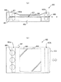
図12は、本発明の電子機器を電子ペーパーに適用した場合の実施形態を示す斜視図である。
図12に示す電子ペーパー600は、紙と同様の質感および柔軟性を有するリライタブルシートで構成される本体601と、表示ユニット602とを備えている。このような電子ペーパー600では、表示ユニット602が、前述したような表示装置20で構成されている。
FIG. 12 is a perspective view showing an embodiment when the electronic apparatus of the present invention is applied to electronic paper.
An
次に、本発明の電子機器をディスプレイに適用した場合の実施形態について説明する。
図13は、本発明の電子機器をディスプレイに適用した場合の実施形態を示す図である。このうち、図13中(a)は断面図、(b)は平面図である。
図13に示すディスプレイ(表示装置)800は、本体部801と、この本体部801に対して着脱自在に設けられた電子ペーパー600とを備えている。なお、この電子ペーパー600は、前述したような構成、すなわち、図12に示す構成と同様である。
Next, an embodiment when the electronic apparatus of the present invention is applied to a display will be described.
FIG. 13 is a diagram showing an embodiment when the electronic apparatus of the present invention is applied to a display. Among these, (a) in FIG. 13 is a sectional view and (b) is a plan view.
A display (display device) 800 illustrated in FIG. 13 includes a
本体部801は、その側部(図13(a)中、右側)に電子ペーパー600を挿入可能な挿入口805が形成され、また、内部に二組の搬送ローラ対802a、802bが設けられている。電子ペーパー600を、挿入口805を介して本体部801内に挿入すると、電子ペーパー600は、搬送ローラ対802a、802bにより挟持された状態で本体部801に設置される。
The
また、本体部801の表示面側(図13(b)中、紙面手前側)には、矩形状の孔部803が形成され、この孔部803には、透明ガラス板804が嵌め込まれている。これにより、本体部801の外部から、本体部801に設置された状態の電子ペーパー600を視認することができる。すなわち、このディスプレイ800では、本体部801に設置された状態の電子ペーパー600を、透明ガラス板804において視認させることで表示面を構成している。
A
また、電子ペーパー600の挿入方向先端部(図13(a)中、左側)には、端子部806が設けられており、本体部801の内部には、電子ペーパー600を本体部801に設置した状態で端子部806が接続されるソケット807が設けられている。このソケット807には、コントローラー808と操作部809とが電気的に接続されている。
このようなディスプレイ800では、電子ペーパー600は、本体部801に着脱自在に設置されており、本体部801から取り外した状態で携帯して使用することもできる。これにより、利便性が向上する。
In addition, a
In such a
以上、本発明の電気泳動粒子の製造方法、電気泳動分散液、表示装置および電子機器を、図示の実施形態に基づいて説明したが、本発明はこれらに限定されるものではなく、各部の構成は、同様の機能を有する任意の構成のものに置換することができる。また、本発明に、他の任意の構成物が付加されていてもよい。また、各実施形態を適宜組み合わせてもよい。
また、前述した実施形態では、高分子鎖を含む化合物として、シリコーン主鎖を有するシロキサン系化合物を用いた場合を例に説明したが、これに限定されず、高分子鎖を含む化合物としては、分散媒に対する粒子の分散性を高める特性を有し、かつ、液性媒体中で粒子の表面と反応して化学結合するものであれば、例えば、シリコーン側鎖を有する高分子であってもよい。
The electrophoretic particle manufacturing method, electrophoretic dispersion liquid, display device, and electronic apparatus of the present invention have been described based on the illustrated embodiments. However, the present invention is not limited to these, and the configuration of each part Can be replaced with any structure having a similar function. In addition, any other component may be added to the present invention. Moreover, you may combine each embodiment suitably.
In the above-described embodiment, the case where a siloxane-based compound having a silicone main chain is used as an example of a compound including a polymer chain is described as an example. However, the present invention is not limited thereto, For example, a polymer having a silicone side chain may be used as long as it has the property of enhancing the dispersibility of the particles in the dispersion medium and can chemically bond with the surface of the particles in the liquid medium. .
次に、本発明の具体的実施例について説明する。
1.電気泳動分散液の製造
以下のようにして電気泳動分散液を製造した。なお、各参考例、各実施例および各参考例における製造条件をそれぞれ表1に示す。
(実施例1)
[1]<シロキサン系化合物の前駆体の製造>
まず、丸底フラスコに、下記式(3)で示されるシリコーンオイルと、その中に含まれるシリコーンオイル由来の反応性官能基に対して1当量以上の反応性官能基を含むシランカップリング剤と、トルエンと、を混合し、そこに白金触媒を加えた。得られた混合物を撹拌し、加熱した状態で放置した。次いで、室温に冷却し、減圧下で溶媒を除去し、残存物を乾燥させた。以上のようにして、下記式(4)に示す、変性シリコーンオイルとシランカップリング剤との反応物(シロキサン系化合物の構造を含むカップリング剤)がシロキサン系化合物の前駆体(以下、「カップリング剤A」と称す)として得られた。このシロキサン系化合物の分子量を測定したところ、16,000であった。
Next, specific examples of the present invention will be described.
1. Production of electrophoretic dispersion An electrophoretic dispersion was produced as follows. In addition, Table 1 shows manufacturing conditions in each reference example, each example, and each reference example.
Example 1
[1] <Production of siloxane compound precursor>
First, a silicone oil represented by the following formula (3) in a round bottom flask, and a silane coupling agent containing a reactive functional group of 1 equivalent or more with respect to the reactive functional group derived from the silicone oil contained therein And toluene were mixed, and a platinum catalyst was added thereto. The resulting mixture was stirred and left to heat. It was then cooled to room temperature, the solvent was removed under reduced pressure and the residue was dried. As described above, the reaction product of the modified silicone oil and the silane coupling agent (coupling agent including the structure of the siloxane compound) represented by the following formula (4) is a precursor of the siloxane compound (hereinafter referred to as “cup”). Obtained as “ringing agent A”). The molecular weight of the siloxane compound was measured and found to be 16,000.

[2]
次いで、上記[1]で得られたシロキサン系化合物を用い、以下の結合工程および除去工程を行って、電気泳動分散液を得た。
<結合工程(造粒工程)>
まず、100mLのガラス製の容器に、母粒子として粒径270nmのチタニア母粒子(石原産業社製「CR−97」)3gと、液性媒体としてのシリコーンオイル(信越化学工業社製「KF−96L−2cs」(動粘度が2mm2/s))15gとを入れ、これらを混合し、チタニア母粒子を液性媒体中に分散させた。
その後、得られた混合物に、上記[1]で得られたシロキサン系化合物0.3gを添加した。
[2]
Next, using the siloxane compound obtained in [1] above, the following bonding step and removal step were performed to obtain an electrophoretic dispersion.
<Bonding process (granulation process)>
First, in a 100 mL glass container, 3 g of titania mother particles (“CR-97” manufactured by Ishihara Sangyo Co., Ltd.) having a particle size of 270 nm as a mother particle and silicone oil (“KF-” manufactured by Shin-Etsu Chemical Co., Ltd.) as a liquid medium are used. 96L-2cs ”(kinematic viscosity is 2 mm 2 / s), and these were mixed to disperse the titania mother particles in the liquid medium.
Thereafter, 0.3 g of the siloxane compound obtained in [1] above was added to the obtained mixture.
次に、得られた混合物を、超音波洗浄機を用いて、分散処理を行った。さらに、容器を断熱材で覆い、ホットスターラー(アズワン社製「1−5477−02」)を用いて、温度180℃(反応温度)、で加熱撹拌を行った。これにより、チタニア母粒子の表面とシロキサン系化合物の前駆体とを反応させ、チタニア母粒子の表面にシロキサン系化合物を結合させた電気泳動粒子が液性媒体中に分散した分散液(洗浄前の電気泳動分散液)を得た。 Next, the obtained mixture was subjected to dispersion treatment using an ultrasonic cleaner. Furthermore, the container was covered with a heat insulating material, and heated and stirred at a temperature of 180 ° C. (reaction temperature) using a hot stirrer (“1-5477-02” manufactured by ASONE). Thereby, the surface of the titania mother particle is reacted with the precursor of the siloxane compound, and the electrophoretic particles in which the siloxane compound is bonded to the surface of the titania mother particle are dispersed in the liquid medium (before washing) Electrophoresis dispersion liquid) was obtained.
<除去工程(洗浄工程)>
結合工程で得られた分散液を遠心瓶に移し、洗浄溶媒(信越シリコーン社製「KF−96L−2cs」)で重量調整した後、遠心分離機(TOMY社製「微量高速冷却遠心機 MX−207」)を用いて、遠沈して、上澄み液をデカンテーションした(洗浄1回目)。
同様の洗浄を繰り返した後、沈殿物に洗浄溶媒を添加し、40wt%に調整した。これにより、チタニア母粒子の表面にシロキサン系化合物を結合させた電気泳動粒子が洗浄溶媒(分散媒)中に分散した分散液(洗浄後の(シロキサン系化合物の前駆体を除去した)電気泳動分散液)を得た。
<Removal process (cleaning process)>
The dispersion obtained in the binding step is transferred to a centrifuge bottle, adjusted in weight with a washing solvent (“KF-96L-2cs” manufactured by Shin-Etsu Silicone Co., Ltd.), and then centrifuged (“trace high speed cooling centrifuge MX- manufactured by TOMY”). 207 "), and the supernatant was decanted (first wash).
After repeating the same washing, a washing solvent was added to the precipitate to adjust to 40 wt%. As a result, the electrophoretic dispersion in which the electrophoretic particles in which the siloxane compound is bonded to the surface of the titania mother particle are dispersed in the cleaning solvent (dispersion medium) (the siloxane compound precursor is removed after the cleaning). Liquid).
(参考例1)
除去工程を省略した以外は、実施例1と同様にして、参考例1の電気泳動分散液を得た。
ここで、参考例1の電気泳動分散液は、実施例1の洗浄前の電気泳動分散液である。
(Reference Example 1)
The electrophoretic dispersion liquid of Reference Example 1 was obtained in the same manner as Example 1 except that the removing step was omitted.
Here, the electrophoresis dispersion liquid of Reference Example 1 is the electrophoresis dispersion liquid before washing of Example 1.
(実施例2)
シロキサン系化合物の前駆体の製造に際し、前記式(3)中のnを300〜2000、前記式(4)中のnを300〜2000とした以外は、前述した実施例1と同様にして、実施例2の電気泳動分散液を得た。以下、本実施例で用いたシロキサン系化合物の分子量は60,000であった。この前駆体を「カップリング剤B」と称す。
(参考例2)
除去工程を省略した以外は、実施例2と同様にして、参考例2の電気泳動分散液を得た。
ここで、参考例2の電気泳動分散液は、実施例2の洗浄前の電気泳動分散液である。
(Example 2)
In the production of the precursor of the siloxane compound, the same as in Example 1 except that n in the formula (3) is 300 to 2000 and n in the formula (4) is 300 to 2000, The electrophoretic dispersion liquid of Example 2 was obtained. Hereinafter, the molecular weight of the siloxane compound used in this example was 60,000. This precursor is referred to as “coupling agent B”.
(Reference Example 2)
An electrophoretic dispersion liquid of Reference Example 2 was obtained in the same manner as Example 2 except that the removing step was omitted.
Here, the electrophoresis dispersion liquid of Reference Example 2 is the electrophoresis dispersion liquid before washing of Example 2.
(実施例3)
シロキサン系化合物の前駆体に代えて、シリコーンマクロマー系分散剤(帯電基なし)を用いた以外は、前述した実施例1と同様にして、実施例3の電気泳動分散液を得た。
本例のシリコーンマクロマー系分散剤は、以下のようにして製造した。
1−メトキシ−2−プロパノールに、シリコーン鎖を持つ重合成分として「サイラプレーンFM−0711(チッソ社製)」15mol%と、疎水性の重合成分としてメタクリル酸メチル65mol%と、ポリアルキレングリコール構造を持つ重合成分としてメトキシポリ(エチレングリコール)9メタクリレート(新中村化学社製)5mol%と、親水性の重合成分としてメタクリル酸15mol%と、を溶解するとともに、重合開始剤(ジメチル−2,2‘−アゾビス(2−メチルプロピオネート「V−601」、和光純薬社製)を全重合成分に対する比率で1.5mol%溶解させ、窒素バブリングにより酸素除去し、80℃で重合を行った。途中、重合開始2時間後、4時間後に重合開始剤(V−601)を全重合成分に対する比率で1.5mol%追添し、合計6時間重合した。重合後、精製処理および乾燥を行い、シリコーンマクロマー系分散剤を得た。
そして、得られたシリコーンマクロマー系分散剤を、チタニア母粒子および液性媒体からなる混合物に添加し、加熱、撹拌することにより、洗浄前の電気泳動分散液を得た。なお、本実施例で用いたシリコーンマクロマー系分散剤は、粒子表面に物理的に結合するタイプの分散剤である。
(参考例3)
除去工程を省略した以外は、実施例3と同様にして、参考例3の電気泳動分散液を得た。
ここで、参考例3の電気泳動分散液は、実施例3の洗浄前の電気泳動分散液である。
(Example 3)
An electrophoretic dispersion liquid of Example 3 was obtained in the same manner as in Example 1 except that a silicone macromer dispersant (no charging group) was used instead of the siloxane compound precursor.
The silicone macromer dispersant of this example was produced as follows.
In 1-methoxy-2-propanol, 15 mol% of “Silaplane FM-0711 (manufactured by Chisso)” as a polymerization component having a silicone chain, 65 mol% of methyl methacrylate as a hydrophobic polymerization component, and a polyalkylene glycol structure While dissolving 5 mol% of methoxypoly (ethylene glycol) 9 methacrylate (manufactured by Shin-Nakamura Chemical Co., Ltd.) as a polymerization component and 15 mol% of methacrylic acid as a hydrophilic polymerization component, a polymerization initiator (dimethyl-2,2′- Azobis (2-methylpropionate “V-601”, manufactured by Wako Pure Chemical Industries, Ltd.) was dissolved at a ratio of 1.5 mol% with respect to the total polymerization components, and oxygen was removed by nitrogen bubbling, followed by polymerization at 80 ° C. The polymerization initiator (V-601) was added at a ratio to the
Then, the obtained silicone macromer dispersant was added to a mixture composed of titania mother particles and a liquid medium, and heated and stirred to obtain an electrophoretic dispersion before washing. The silicone macromer dispersant used in this example is a type of dispersant that physically binds to the particle surface.
(Reference Example 3)
An electrophoretic dispersion liquid of Reference Example 3 was obtained in the same manner as Example 3 except that the removing step was omitted.
Here, the electrophoresis dispersion liquid of Reference Example 3 is the electrophoresis dispersion liquid before washing of Example 3.
(実施例4)
シロキサン系化合物の前駆体に代えて、シリコーンマクロマー系分散剤(帯電基あり)を用いた以外は、前述した実施例1と同様にして、実施例4の電気泳動分散液を得た。
本例のシリコーンマクロマー系分散剤は、シリコーン鎖を持つ重合成分として「サイラプレーンFM−0721(チッソ社製)」と、帯電基を持つ重合成分としてフェノキシポリエチレングリコールアクリレートAMP−10G(新中村化学製)と、及びHEMA(2−ヒドロキシエチルメタクリレートと、反応性基(架橋性基)を持つ重合成分としてイソシアネート系モノマー(ブロック化されたイソシアネート基を有するイソシアネート系モノマー「カレンズMOI−BP(昭和電工社製)」との共重合体(モル比3/26/69/2)である。
そして、このシリコーンマクロマー系分散剤を、チタニア母粒子および液性媒体からなる混合物に添加し、加熱、撹拌することにより、洗浄前の電気泳動分散液を得た。なお、本実施例で用いたシリコーンマクロマー系分散剤は、粒子表面に物理的に吸着するタイプの分散剤である。
(参考例4)
除去工程を省略した以外は、実施例4と同様にして、参考例4の電気泳動分散液を得た。
ここで、参考例4の電気泳動分散液は、実施例4の洗浄前の電気泳動分散液である。
Example 4
An electrophoretic dispersion of Example 4 was obtained in the same manner as in Example 1 except that a silicone macromer dispersant (with a charged group) was used instead of the siloxane compound precursor.
The silicone macromer-based dispersant of this example includes “Silaplane FM-0721 (manufactured by Chisso)” as a polymerization component having a silicone chain, and phenoxypolyethylene glycol acrylate AMP-10G (manufactured by Shin-Nakamura Chemical Co., Ltd.) as a polymerization component having a charging group ), And HEMA (2-hydroxyethyl methacrylate and a polymerization component having a reactive group (crosslinkable group) as an isocyanate monomer (an isocyanate monomer having a blocked isocyanate group “Karenz MOI-BP (Showa Denko) (
The silicone macromer-based dispersant was added to a mixture composed of titania mother particles and a liquid medium, and heated and stirred to obtain an electrophoretic dispersion before washing. The silicone macromer dispersant used in this example is a type of dispersant that is physically adsorbed on the particle surface.
(Reference Example 4)
The electrophoretic dispersion liquid of Reference Example 4 was obtained in the same manner as Example 4 except that the removing step was omitted.
Here, the electrophoresis dispersion liquid of Reference Example 4 is the electrophoresis dispersion liquid before washing of Example 4.
(実施例5〜7)
液性媒体として、シリコーンオイル(信越化学工業社製「KF−96L−2cs」)15gと水0.003gとの混合溶液を用いた以外は、前述した実施例1〜3と同様にして、実施例5〜7の電気泳動分散液を得た。
(参考例5〜7)
液性媒体として、シリコーンオイル(信越化学工業社製「KF−96L−2cs」)15gと水0.003gとの混合溶液を用いた以外は、前述した参考例1〜3と同様にして電気泳動分散液を得た。
ここで、参考例5の電気泳動分散液は、実施例5の洗浄前の電気泳動分散液である。また、参考例6の電気泳動分散液は、実施例6の洗浄前の電気泳動分散液である。また、参考例7の電気泳動分散液は、実施例7の洗浄前の電気泳動分散液である。
(Examples 5-7)
As a liquid medium, the same procedure as in Examples 1 to 3 was performed except that a mixed solution of 15 g of silicone oil (“KF-96L-2cs” manufactured by Shin-Etsu Chemical Co., Ltd.) and 0.003 g of water was used. The electrophoretic dispersions of Examples 5 to 7 were obtained.
(Reference Examples 5-7)
Electrophoresis in the same manner as in Reference Examples 1 to 3 except that a mixed solution of 15 g of silicone oil (“KF-96L-2cs” manufactured by Shin-Etsu Chemical Co., Ltd.) and 0.003 g of water was used as the liquid medium. A dispersion was obtained.
Here, the electrophoresis dispersion liquid of Reference Example 5 is the electrophoresis dispersion liquid before washing of Example 5. Further, the electrophoresis dispersion liquid of Reference Example 6 is the electrophoresis dispersion liquid before washing of Example 6. Further, the electrophoresis dispersion liquid of Reference Example 7 is the electrophoresis dispersion liquid before washing of Example 7.
(実施例8、9)
液性媒体として、粘度の異なるシリコーンオイル(信越化学工業社製「KF−96L−20cs」(動粘度20mm2/s))を用いた以外は、実施例1、2と同様にして、実施例8、9の電気泳動分散液を得た。
(参考例8、9)
液性媒体として、粘度の異なるシリコーンオイル(信越化学工業社製「KF−96L−20cs」)を用いた以外は、参考例1、2と同様にして、参考例8、9の電気泳動分散液を得た。
(Examples 8 and 9)
In the same manner as in Examples 1 and 2, except that silicone oil having a different viscosity (“KF-96L-20cs” (
(Reference Examples 8 and 9)
The electrophoretic dispersions of Reference Examples 8 and 9 were the same as Reference Examples 1 and 2, except that silicone oils having different viscosities (“KF-96L-20cs” manufactured by Shin-Etsu Chemical Co., Ltd.) were used as the liquid medium. Got.
(実施例10)
液性媒体および分散媒として、エステル系溶媒(ライオン社製「パステルM8」)を用いた以外は、実施例1と同様にして、実施例10の電気泳動分散液を得た。
(実施例11)
液性媒体および分散媒として、パラフィン系溶媒(エクソン化学社製「Isopar−M」)を用いた以外は、実施例1と同様にして、実施例11の電気泳動分散液を得た。
(Example 10)
The electrophoretic dispersion liquid of Example 10 was obtained in the same manner as in Example 1 except that an ester solvent (“Pastel M8” manufactured by Lion Corporation) was used as the liquid medium and the dispersion medium.
(Example 11)
The electrophoretic dispersion liquid of Example 11 was obtained in the same manner as in Example 1 except that a paraffinic solvent (“Isopar-M” manufactured by Exxon Chemical Co., Ltd.) was used as the liquid medium and the dispersion medium.
(実施例12)
母粒子として、粒径が100nmのチタニア母粒子(三菱マテリアル社製「SC−13M−T」)を用いた以外は、実施例1と同様にして、実施例12の電気泳動分散液を得た。
(実施例13)
シロキサン系化合物の前駆体として、カップリング剤Bを用いた以外は、前述した実施例12と同様にして、実施例12の電気泳動分散液を得た。
(Example 12)
An electrophoretic dispersion liquid of Example 12 was obtained in the same manner as Example 1 except that titania mother particles having a particle size of 100 nm (“SC-13M-T” manufactured by Mitsubishi Materials Corporation) were used as the mother particles. .
(Example 13)
An electrophoretic dispersion liquid of Example 12 was obtained in the same manner as in Example 12 except that coupling agent B was used as the precursor of the siloxane compound.
(実施例14、15)
液性媒体として、シリコーンオイル(信越化学工業社製「KF−96L−2cs」)15gと水0.003gとの混合溶液を用いた以外は、前述した実施例12、13と同様にして、実施例14、15の電気泳動分散液を得た。
(実施例16)
液性媒体として、粘度の異なるシリコーンオイル(信越化学工業社製「KF−96L−20cs」)を用いた以外は、実施例12と同様にして、実施例16の電気泳動分散液を得た。
(Examples 14 and 15)
As a liquid medium, the same procedure as in Examples 12 and 13 was performed except that a mixed solution of 15 g of silicone oil (“KF-96L-2cs” manufactured by Shin-Etsu Chemical Co., Ltd.) and 0.003 g of water was used. The electrophoretic dispersions of Examples 14 and 15 were obtained.
(Example 16)
An electrophoretic dispersion of Example 16 was obtained in the same manner as Example 12 except that silicone oil having a different viscosity (“KF-96L-20cs” manufactured by Shin-Etsu Chemical Co., Ltd.) was used as the liquid medium.
(実施例17)
液性媒体としてシリコーンオイル(信越化学工業社製「KF−96L−20cs」)と水0.003gとの混合溶液を用いた以外は、前述した実施例13と同様にして、実施例17の電気泳動分散液を得た。
以上のような実施例1〜17および参考例1〜9における母粒子の種類、液性媒体の種類、シロキサン系化合物の前駆体の種類および除去工程の有無についてまとめたものを下記表1に示す。なお、表1には、電気泳動分散液の分散性、泳動性および抵抗値についての評価結果も示されているが、この評価およびその方法については、後に詳述する。
(Example 17)
The electricity of Example 17 was the same as Example 13 described above except that a mixed solution of silicone oil (“KF-96L-20cs” manufactured by Shin-Etsu Chemical Co., Ltd.) and 0.003 g of water was used as the liquid medium. An electrophoretic dispersion was obtained.
Table 1 below summarizes the types of base particles, types of liquid medium, types of precursors of siloxane compounds, and the presence or absence of a removal step in Examples 1 to 17 and Reference Examples 1 to 9 as described above. . Table 1 also shows the evaluation results for the dispersibility, electrophoretic properties, and resistance values of the electrophoretic dispersion, and this evaluation and its method will be described in detail later.
(実施例18〜41、参考例10〜17)
液性媒体として、シリコーンオイル(信越化学工業社製「KF−96L−2cs」)15gを用いるとともに、結合工程において、母粒子および液性媒体からなる混合物にシロキサン系化合物の前駆体を添加する際、シロキサン系化合物の前駆体のシリコーン溶液を用い、結合工程における反応温度、添加するシロキサン系化合物の前駆体の溶液濃度および除去工程における洗浄回数を下記表2に示す条件とした以外は、実施例1と同様にして、実施例18〜41、参考例10〜17の電気泳動分散液を得た。
(Examples 18 to 41, Reference Examples 10 to 17)
When using 15 g of silicone oil (“KF-96L-2cs” manufactured by Shin-Etsu Chemical Co., Ltd.) as the liquid medium and adding the precursor of the siloxane compound to the mixture of the mother particles and the liquid medium in the bonding step Except for using the silicone solution of the precursor of the siloxane compound, the reaction temperature in the bonding step, the solution concentration of the precursor of the siloxane compound to be added, and the number of washings in the removal step were the conditions shown in Table 2 below. In the same manner as in Example 1, electrophoretic dispersions of Examples 18 to 41 and Reference Examples 10 to 17 were obtained.
なお、表2には、電気泳動分散液の分散性および抵抗値についての評価結果も示されているが、この評価およびその方法については、後に詳述する。 Table 2 also shows the evaluation results for the dispersibility and the resistance value of the electrophoretic dispersion, and this evaluation and its method will be described in detail later.
(実施例42〜65)
結合工程において、母粒子および液性媒体からなる混合物にシロキサン系化合物の前駆体を添加する際、シロキサン系化合物の前駆体の2wt%シリコーン溶液を用い、母粒子の種類、液性媒体の種類(シリコーンオイル(信越化学工業社製「KF−96L−0.5cs」(動粘度0.5mm2/s)、「KF−96L−2cs」、「KF−96L−20cs」、「KF−96L−100cs」(動粘度100mm2/s)))および添加するシロキサン系化合物の前駆体の溶液量を下記表3に示す条件とした以外は、実施例1と同様にして、実施例42〜65の電気泳動分散液を得た。
(Examples 42 to 65)
In the bonding step, when the siloxane compound precursor is added to the mixture of the mother particles and the liquid medium, a 2 wt% silicone solution of the siloxane compound precursor is used, and the type of the mother particles and the type of the liquid medium ( Silicone oil (“KF-96L-0.5cs” (Kinetic viscosity 0.5 mm 2 / s) manufactured by Shin-Etsu Chemical Co., Ltd., “KF-96L-2cs”, “KF-96L-20cs”, “KF-96L-100cs” (
なお、表3には、電気泳動分散液の分散性および抵抗値についての評価結果も示されているが、この評価およびその方法については、後に詳述する。 Table 3 also shows the evaluation results for the dispersibility and resistance value of the electrophoretic dispersion, and this evaluation and the method thereof will be described in detail later.
2.電気泳動分散液の評価
2.1 分散性の評価
各実施例および各参考例の電気泳動分散液を櫛歯状電極セルへ注入し、セル内を光学顕微鏡を用いて観察した。さらに分散性があることが確認できたサンプルについては日機装社製レーザー回折・散乱式粒度分析 MT3400IIを用いて測定を行い、以下の評価基準に従い、分散性を評価した。
2. 2. Evaluation of electrophoretic dispersion 2.1 Evaluation of dispersibility The electrophoretic dispersions of Examples and Reference Examples were injected into a comb-like electrode cell, and the inside of the cell was observed using an optical microscope. Further, the sample confirmed to have dispersibility was measured using a laser diffraction / scattering particle size analysis MT3400II manufactured by Nikkiso Co., Ltd., and the dispersibility was evaluated according to the following evaluation criteria.
◎:凝集がなく、かつ、単分散である。
○:凝集がないが、多分散である。
△:凝集があるが、単分散である。
×:凝集があり、かつ、多分散である。
なお、上記評価基準において、電気泳動粒子の体積平均粒径(Mv)が母粒子の平均粒径に対して1.2倍以上となった場合を多分散と判断した。
A: No aggregation and monodisperse.
○: There is no aggregation, but polydispersion.
Δ: Although there is aggregation, it is monodispersed.
X: There is aggregation and polydispersion.
In the above evaluation criteria, the case where the volume average particle size (Mv) of the electrophoretic particles was 1.2 times or more than the average particle size of the mother particles was judged as polydisperse.
2.2 抵抗率の評価
各実施例および各参考例の電気泳動分散液について、体積固有抵抗ρv(Ω・cm)を測定し、以下の評価基準に従い、抵抗値の評価を行った。
○:ρv>1011
△:109≦ρv≦1011
×:ρv<109
以上のような評価基準に従った分散性および抵抗値の評価結果に基づき、いずれかの評価結果の悪い方を総合評価として、表1〜3に示す。
2.2 Evaluation of Resistivity About the electrophoretic dispersion liquid of each example and each reference example, the volume resistivity ρv (Ω · cm) was measured, and the resistance value was evaluated according to the following evaluation criteria.
○: ρv> 10 11
Δ: 10 9 ≦ ρv ≦ 10 11
×: ρv <10 9
Based on the evaluation results of the dispersibility and the resistance value according to the evaluation criteria as described above, Tables 1 to 3 show the worse one of the evaluation results as a comprehensive evaluation.
また、実施例1〜17および参考例1〜9の電気泳動分散液については、電気泳動分散液を挟んだ1対の電極間に所定の電圧(定電圧)を印加したときの電気泳動粒子の動きを観察し、以下の評価基準に従い、泳動性の評価を行い、その結果を表1に示す。
++:プラス電極側に大きく動く。
+:プラス電極側に動くが、その動きが小さい。
+/−:プラス電極側に動くものと、マイナス電極側に動くものとが混在している。
−:マイナス電極側に動くが、その動きが小さい。
−−:マイナス電極側に大きく動く。
*:不動である。
以上のような評価の結果、表1〜3に示すように、各実施例に係る電気泳動分散液は、対応する除去工程を行わない各参考例に係る電気泳動分散液に比し、抵抗値が低くなることがわかる。
Moreover, about the electrophoretic dispersion liquid of Examples 1-17 and Reference Examples 1-9, when a predetermined voltage (constant voltage) is applied between a pair of electrodes sandwiching the electrophoretic dispersion liquid, The movement was observed, and migration was evaluated according to the following evaluation criteria. The results are shown in Table 1.
++: Moves greatly toward the positive electrode.
+: Moves toward the positive electrode, but the movement is small.
+/-: A mixture that moves toward the plus electrode and a zone that moves toward the minus electrode are mixed.
-: Moves toward the negative electrode, but the movement is small.
-: Moves greatly toward the negative electrode.
*: It is immobile.
As a result of the evaluation as described above, as shown in Tables 1 to 3, the electrophoretic dispersion liquid according to each example has a resistance value higher than that of the electrophoretic dispersion liquid according to each reference example in which the corresponding removal step is not performed. It turns out that becomes low.
1‥‥基部 2‥‥基部 3‥‥電極 4‥‥電極 5‥‥封止部 7‥‥分散媒 8‥‥液性媒体 11‥‥基板 12‥‥基板 20‥‥表示装置 21‥‥表示シート 22‥‥回路基板 40‥‥マイクロカプセル 41‥‥バインダー 70‥‥電気泳動粒子 71‥‥コア粒子 72‥‥シロキサン系化合物 72A‥‥前駆体 91‥‥壁部 92‥‥壁部 100‥‥分散液 101‥‥空間 111‥‥表示面 300‥‥容器 400‥‥表示層 401‥‥カプセル本体 600‥‥電子ペーパー 601‥‥本体 602‥‥表示ユニット 721‥‥構造 722‥‥構造 800‥‥ディスプレイ 801‥‥本体部 802a、802b‥‥搬送ローラ対 803‥‥孔部 804‥‥透明ガラス板 805‥‥挿入口 806‥‥端子部 807‥‥ソケット 808‥‥コントローラー 809‥‥操作部
DESCRIPTION OF
Claims (20)
液性媒体中で、前記化合物を前記粒子の表面に結合させる結合工程と、
前記粒子に結合していない前記化合物またはその前駆体を除去する除去工程と、を有し、
前記除去工程は、前記化合物が結合している前記粒子が前記液性媒体と接した状態を維持しつつ行うことを特徴とする電気泳動分散液の製造方法。 A method for producing an electrophoretic dispersion in which electrophoretic particles in which a compound containing a polymer chain is bound to the surface of the particles are dispersed in a dispersion medium,
A binding step of binding the compound to the surface of the particles in a liquid medium;
Removing the compound or its precursor that is not bound to the particles,
The method for producing an electrophoretic dispersion, wherein the removing step is performed while maintaining the state in which the particles to which the compound is bonded are in contact with the liquid medium.
前記除去工程中または前記除去工程の後に、前記分散媒を加える工程と、前記液性媒体を除去する工程とを有する請求項1または2に記載の電気泳動分散液の製造方法。 The liquid medium is different from the dispersion medium and has compatibility with the dispersion medium,
The method for producing an electrophoretic dispersion according to claim 1, further comprising a step of adding the dispersion medium during the removal step or after the removal step, and a step of removing the liquid medium.
前記結合工程では、前記液性媒体の重量に対して0.01wt%以上0.1wt%以下の水を添加する請求項1ないし5のいずれか1項に記載の電気泳動分散液。 The number average molecular weight in terms of polystyrene of the compound is 40,000 or more,
6. The electrophoretic dispersion according to claim 1, wherein in the binding step, 0.01 wt% or more and 0.1 wt% or less of water is added with respect to the weight of the liquid medium.
前記結合工程では、前記粒子の重量に対して、前記液性媒体の重量を15倍以上60倍以下とする請求項1ないし6のいずれか1項に記載の電気泳動分散液の製造方法。 The number average particle diameter of the particles is 50 nm or more and 150 nm or less,
The method for producing an electrophoretic dispersion according to any one of claims 1 to 6, wherein in the binding step, the weight of the liquid medium is set to 15 times or more and 60 times or less with respect to the weight of the particles.
前記結合工程では、前記カップリング剤由来の加水分解性基と前記粒子の表面とを脱水縮合反応させる請求項14または15に記載の電気泳動分散液の製造方法。 The precursor is a reaction product obtained by reacting a silicone oil and a coupling agent,
The method for producing an electrophoretic dispersion according to claim 14 or 15, wherein in the binding step, a hydrolyzable group derived from the coupling agent and a surface of the particle are subjected to a dehydration condensation reaction.
前記結合工程では、前記シリコーンオイル由来の官能基と前記粒子の表面とを反応させる請求項14または15に記載の電気泳動分散液の製造方法。 The precursor is silicone oil;
The method for producing an electrophoretic dispersion according to claim 14 or 15, wherein, in the binding step, the functional group derived from the silicone oil is reacted with the surface of the particle.
前記第1基板に対向配置され、第2電極が設けられた第2基板と、
前記第1基板と前記第2基板との間に設けられ、請求項18に記載の電気泳動分散液を含む表示層と、を有することを特徴とする表示装置。 A first substrate provided with a first electrode;
A second substrate disposed opposite to the first substrate and provided with a second electrode;
A display device, comprising: a display layer provided between the first substrate and the second substrate and containing the electrophoretic dispersion according to claim 18.
Priority Applications (3)
| Application Number | Priority Date | Filing Date | Title |
|---|---|---|---|
| JP2014008135A JP2015138058A (en) | 2014-01-20 | 2014-01-20 | Method of manufacturing electrophoresis dispersion liquid, electrophoresis dispersion liquid, display device and electronic apparatus |
| CN201510015482.2A CN104793424A (en) | 2014-01-20 | 2015-01-13 | Method of manufacturing electrophoresis dispersion liquid, electrophoresis dispersion liquid, display device and electronic apparatus |
| US14/599,579 US20150205180A1 (en) | 2014-01-20 | 2015-01-19 | Method of manufacturing electrophoresis dispersion liquid, electrophoresis dispersion liquid, display device and electronic apparatus |
Applications Claiming Priority (1)
| Application Number | Priority Date | Filing Date | Title |
|---|---|---|---|
| JP2014008135A JP2015138058A (en) | 2014-01-20 | 2014-01-20 | Method of manufacturing electrophoresis dispersion liquid, electrophoresis dispersion liquid, display device and electronic apparatus |
Publications (1)
| Publication Number | Publication Date |
|---|---|
| JP2015138058A true JP2015138058A (en) | 2015-07-30 |
Family
ID=53769112
Family Applications (1)
| Application Number | Title | Priority Date | Filing Date |
|---|---|---|---|
| JP2014008135A Pending JP2015138058A (en) | 2014-01-20 | 2014-01-20 | Method of manufacturing electrophoresis dispersion liquid, electrophoresis dispersion liquid, display device and electronic apparatus |
Country Status (1)
| Country | Link |
|---|---|
| JP (1) | JP2015138058A (en) |
Cited By (2)
| Publication number | Priority date | Publication date | Assignee | Title |
|---|---|---|---|---|
| JP2017043724A (en) * | 2015-08-28 | 2017-03-02 | キヤノン株式会社 | Resin fine particle and dispersion liquid |
| US10969647B2 (en) | 2015-03-11 | 2021-04-06 | E Ink Corporation | Electrophoretic particle, method of manufacturing electrophoretic particle, electrophoresis dispersion liquid, electrophoresis sheet, electrophoresis device, and electronic apparatus |
-
2014
- 2014-01-20 JP JP2014008135A patent/JP2015138058A/en active Pending
Cited By (2)
| Publication number | Priority date | Publication date | Assignee | Title |
|---|---|---|---|---|
| US10969647B2 (en) | 2015-03-11 | 2021-04-06 | E Ink Corporation | Electrophoretic particle, method of manufacturing electrophoretic particle, electrophoresis dispersion liquid, electrophoresis sheet, electrophoresis device, and electronic apparatus |
| JP2017043724A (en) * | 2015-08-28 | 2017-03-02 | キヤノン株式会社 | Resin fine particle and dispersion liquid |
Similar Documents
| Publication | Publication Date | Title |
|---|---|---|
| JP6340814B2 (en) | Electrophoretic particles, method for producing electrophoretic particles, electrophoretic dispersion, display device, and electronic apparatus | |
| JP6326856B2 (en) | Electrophoretic particles, electrophoretic dispersion, display sheet, display device, and electronic device | |
| JP5233225B2 (en) | Image display device | |
| US8526099B2 (en) | Method for manufacturing microcapsules, and microcapsule, electrophoretic device and electric apparatus | |
| US20150205180A1 (en) | Method of manufacturing electrophoresis dispersion liquid, electrophoresis dispersion liquid, display device and electronic apparatus | |
| JP6326854B2 (en) | Electrophoretic particles, electrophoretic dispersion, display sheet, display device, and electronic device | |
| US8547324B2 (en) | Electrophoretic display sheet, electrophoretic display apparatus, and electronic device | |
| JP2008051931A (en) | Electrophoretic display medium | |
| JP2015138058A (en) | Method of manufacturing electrophoresis dispersion liquid, electrophoresis dispersion liquid, display device and electronic apparatus | |
| CN106019759B (en) | Electrophoretic particle, method for producing electrophoretic particle, electrophoretic dispersion liquid, electrophoretic sheet, electrophoretic device, and electronic apparatus | |
| TW201331692A (en) | Electrophoretic particle, method for producing electrophoretic particle, electrophoretic dispersion, electrophoretic sheet, electrophoretic device, and electronic apparatus | |
| JP2015138059A (en) | Method of manufacturing electrophoresis dispersion liquid, electrophoresis dispersion liquid, display device and electronic apparatus | |
| CN105974708B (en) | Electrophoretic particle, method for producing electrophoretic particle, electrophoretic dispersion liquid, electrophoretic sheet, electrophoretic device, and electronic apparatus | |
| JP2015004749A (en) | Electrophoretic dispersion liquid, display sheet, electrophoretic display apparatus, and electronic equipment | |
| JP6851226B2 (en) | Electrophoretic particles, methods for producing electrophoretic particles, electrophoretic dispersions, electrophoretic sheets, electrophoretic devices and electronic devices | |
| JP2017146457A (en) | Electrophoretic dispersion liquid, electrophoretic sheet, electrophoretic device, and electronic apparatus | |
| JP2017054003A (en) | Electrophoretic dispersion liquid, production method of electrophoretic dispersion liquid, electrophoretic sheet, electrophoretic device and electronic apparatus | |
| JP2015138164A (en) | Electrophoretic particles, manufacturing method of the same, electrophoretic dispersion liquid, electrophoretic sheet, electrophoresis apparatus and electronic apparatus | |
| JP5526319B2 (en) | Display sheet, display device, electronic apparatus, and display sheet driving method | |
| JP2012093385A (en) | Display sheet, display device and electronic apparatus | |
| JP2017187615A (en) | Electrophoretic dispersion liquid, production method of electrophoretic dispersion liquid, electrophoretic sheet, electrophoretic device and electronic apparatus | |
| JP2011232452A (en) | Display sheet, display device, and electronic apparatus |