JP2015128473A - Mobile x-ray device - Google Patents
Mobile x-ray device Download PDFInfo
- Publication number
- JP2015128473A JP2015128473A JP2014000339A JP2014000339A JP2015128473A JP 2015128473 A JP2015128473 A JP 2015128473A JP 2014000339 A JP2014000339 A JP 2014000339A JP 2014000339 A JP2014000339 A JP 2014000339A JP 2015128473 A JP2015128473 A JP 2015128473A
- Authority
- JP
- Japan
- Prior art keywords
- handle
- handle member
- size
- ray apparatus
- mobile
- Prior art date
- Legal status (The legal status is an assumption and is not a legal conclusion. Google has not performed a legal analysis and makes no representation as to the accuracy of the status listed.)
- Pending
Links
- 230000037431 insertion Effects 0.000 claims description 6
- 238000003780 insertion Methods 0.000 claims description 6
- 238000003384 imaging method Methods 0.000 description 3
- 125000002066 L-histidyl group Chemical group [H]N1C([H])=NC(C([H])([H])[C@](C(=O)[*])([H])N([H])[H])=C1[H] 0.000 description 2
Images


Landscapes
- Apparatus For Radiation Diagnosis (AREA)
Abstract
Description
この発明は、移動させる際に操作者が把持する操作ハンドルを有する移動型X線装置に関するものである。 The present invention relates to a mobile X-ray apparatus having an operation handle that is gripped by an operator when moved.
従来の回診用X線撮影装置では、複数の車輪を有する台車に、X線管と、車輪を駆動するモータと、モータの駆動を制御する制御部とが搭載されている。また、台車には、台車を移動させる際に操作者が把持する操作ハンドルが設けられている。操作者が操作ハンドルを前方へ押したことがセンサにより検出されると、制御部によりモータが駆動され、台車が前進する。 In a conventional round-trip X-ray imaging apparatus, a cart having a plurality of wheels is equipped with an X-ray tube, a motor that drives the wheels, and a control unit that controls the driving of the motors. The carriage is provided with an operation handle that is held by an operator when the carriage is moved. When it is detected by the sensor that the operator has pushed the operation handle forward, the motor is driven by the control unit and the carriage moves forward.
また、操作者により操作ハンドルが把持されてブレーキ解除スイッチが操作されることにより、ブレーキが解除されて、台車の走行が許容される。操作者が操作ハンドルから手を離すと、ブレーキ解除スイッチがオフになり、台車の走行が禁止される(例えば、特許文献1参照)。 Further, when the operator holds the operation handle and operates the brake release switch, the brake is released and the carriage is allowed to travel. When the operator releases his / her hand from the operation handle, the brake release switch is turned off, and traveling of the carriage is prohibited (for example, see Patent Document 1).
上記のような従来の回診用X線撮影装置では、操作者が操作ハンドルから手を離すと台車の走行が禁止される方式(デッドマン方式)となっているので、台車を走行させるためには操作者が操作ハンドルを把持しブレーキ解除スイッチを押し続ける必要がある。これに対して、操作ハンドルの太さは平均的な手の大きさに合わせて設計されているため、手の大きさが比較的大きい操作者及び小さい操作者には、台車の走行時に操作ハンドルを把持し続けることが負担になる。特に、往復で数km以上の移動が必要な場合には、操作者の手の大きさに合わない操作ハンドルを把持し続けることが大きな負担となる。 In the conventional X-ray imaging apparatus for round trips as described above, since the carriage is prohibited from traveling when the operator removes his / her hand from the operation handle (deadman system), the operation is required to run the carriage. It is necessary for the person to hold the operation handle and keep pressing the brake release switch. On the other hand, since the thickness of the operation handle is designed according to the average hand size, an operator handle with a relatively large hand size can be used when the cart is running. It will be a burden to keep gripping. In particular, when a reciprocation of several km or more is required, it is a heavy burden to continue to hold an operation handle that does not fit the size of the operator's hand.
この発明は、上記のような課題を解決するためになされたものであり、走行時の操作者の負担を軽減し、操作性を向上させることができる移動型X線装置を得ることを目的とする。 The present invention has been made to solve the above-described problems, and an object of the present invention is to provide a mobile X-ray apparatus that can reduce the burden on the operator during traveling and improve operability. To do.
この発明に係る移動型X線装置は、複数の車輪を有する台車、台車に搭載されているX線装置本体、台車に搭載されており、車輪を駆動する走行用モータ、及びハンドル本体と、台車の走行を阻止するブレーキを解除するためのブレーキ解除スイッチとを有しており、かつ台車に設けられている操作ハンドルを備え、操作ハンドルには、ハンドル本体の長さ方向に直角な断面の大きさを変更するためのサイズ調整機構が設けられている。 A mobile X-ray apparatus according to the present invention includes a carriage having a plurality of wheels, an X-ray apparatus body mounted on the carriage, a traveling motor mounted on the carriage and driving the wheels, a handle body, and the carriage. A brake release switch for releasing the brake that prevents the vehicle from traveling, and has an operation handle provided on the carriage, and the operation handle has a cross-sectional size perpendicular to the length direction of the handle body. A size adjusting mechanism for changing the height is provided.
この発明の移動型X線装置は、ハンドル本体の長さ方向に直角な断面の大きさを変更するためのサイズ調整機構が操作ハンドルに設けられているので、走行時の操作者の負担を軽減し、操作性を向上させることができる。 In the mobile X-ray apparatus of the present invention, the size adjustment mechanism for changing the size of the cross section perpendicular to the length direction of the handle body is provided on the operation handle, so the burden on the operator during traveling is reduced. In addition, operability can be improved.
以下、この発明を実施するための形態について、図面を参照して説明する。
実施の形態1.
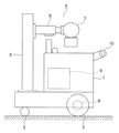
図1はこの発明の実施の形態1による移動型X線装置(回診用X線撮影装置)を示す側面図である。図において、台車1の下部には、複数の車輪として、一対の前輪2及び一対の後輪3が設けられている。台車1上には、X線装置本体4が搭載されている。X線装置本体4は、台車1上に立設された支柱5、支柱5に上下動可能に支持されている伸縮可能なアーム6、及びアーム6の先端に支持されているX線管7を有している。
Hereinafter, embodiments for carrying out the present invention will be described with reference to the drawings.
Embodiment 1 FIG.
FIG. 1 is a side view showing a mobile X-ray apparatus (rounding X-ray imaging apparatus) according to Embodiment 1 of the present invention. In the figure, a pair of
また、台車1内には、後輪3を駆動する走行用モータ8、及び制御部9が搭載されている。制御部9は、操作者の操作に応じてX線装置本体4及び走行用モータ8を制御する。台車1の後部上端には、台車1を走行させる際に操作者が把持する棒状の操作ハンドル(走行ハンドル)10が取り付けられている。
In addition, a traveling
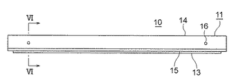
図2は図1の操作ハンドル10を示す正面図、図3は図2の操作ハンドル10を示す底面図、図4は図2の操作ハンドル10を斜め上から見た斜視図、図5は図2の操作ハンドル10を斜め下から見た斜視図、図6は図2のVI−VI線に沿う断面図である。
2 is a front view showing the
操作ハンドル10は、筒状のハンドル本体11、ハンドル本体11内に設けられている複数(この例では2個)のブレーキ解除スイッチ12(図6)、及びブレーキ解除スイッチ12を操作するためのスイッチバー13を有している。
The
ハンドル本体11は、断面U字形の第1のハンドル部材14、及び第1のハンドル部材14に嵌め合わされている断面U字形の第2のハンドル部材15を有している。第1のハンドル部材14は、第2のハンドル部材15の上側に配置されている。
The handle
図6に示すように、第1のハンドル部材14は、互いに対向する一対の第1の側面部14a,14b、及び第1の側面部14a,14bの上端部間に位置する上面部14cを有している。
As shown in FIG. 6, the
第2のハンドル部材15は、第1のハンドル部材14とは上下逆向きに配置されている。第2のハンドル部材15は、互いに対向する一対の第2の側面部15a,15b、及び第2の側面部15a,15bの下端部間に位置する下面部15cを有している。
The
第2の側面部15a,15bは、第1の側面部14a,14b間に挿入されている。また、第2の側面部15aの外面は第1の側面部14aの内面に接しており、第2の側面部15bの外面は第1の側面部14bの内面に接している。
The second
第2のハンドル部材15は、複数の締結具16により第1のハンドル部材14に固定されている。締結具16としては、例えば六角穴付きボルト又は皿ねじ等が用いられる。第2の側面部15a,15bには、締結具16に対応する複数のねじ穴15dが設けられている。ねじ穴15dの数は、締結具16の数よりも多い。
The
この例では、1本の締結具16に対して、3つのねじ穴15dが上下方向に互いに間隔をおいて配置されている。締結具16を締め込むねじ穴15dを選択することにより、第2のハンドル部材15の第1のハンドル部材14への挿入深さ(嵌め合わせ深さ)が段階的に変更可能になっている。これにより、ハンドル本体11の長さ方向(台車1の幅方向)に直角な断面(図6)の大きさ(太さ)が段階的に変更可能となっている。即ち、実施の形態1のサイズ調整機構17は、締結具16及びねじ穴15dにより構成されている。
In this example, three
ブレーキ解除スイッチ12は、台車1の走行を阻止するブレーキ(図示せず)を解除するためのスイッチである。また、ブレーキ解除スイッチ12は、ハンドル本体11の長さ方向(図2の左右方向)に互いに間隔をおいて配置されている。さらに、各ブレーキ解除スイッチ12は、第2の側面部15a,15b間に固定されたスイッチ基板18の下面に取り付けられている。
The
下面部15cには、スイッチバー13を通すスイッチバー孔15eが設けられている。スイッチバー13は、スイッチバー孔15eを通してハンドル本体11から突出している。操作者がハンドル本体11を把持し、スイッチバー13を上方向へ押すことにより、ブレーキ解除スイッチ12が操作され、台車1の走行が許可される。
The
この状態で、操作者がハンドル本体11を前方へ押したことがセンサ(図示せず)により検出されると、制御部9により走行用モータ8が駆動され、台車1が前進する。また、操作者がハンドル本体11を後方へ引っ張ったことがセンサにより検出されると、制御部9により走行用モータ8が駆動され、台車1が後退する。さらに、操作者がハンドル本体11から手を離すと、ブレーキ解除スイッチ12がオフになり、台車1の走行が禁止される。
In this state, when it is detected by a sensor (not shown) that the operator has pushed the
このような移動型X線装置では、ハンドル本体11にサイズ調整機構17が設けられているため、操作者の手の大きさ、好き嫌い、又は握り方等に合わせて、ハンドル本体11の断面の大きさを予め調整しておくことで、走行時の操作者の負担を軽減し、操作性を向上させることができる。
In such a mobile X-ray apparatus, since the handle
実施の形態2.
次に、図7はこの発明の実施の形態2による移動型X線装置の操作ハンドルの断面図である。実施の形態2の操作ハンドルは、ハンドル本体11、及びハンドル本体11の下面に貼り付けられているブレーキ解除スイッチ19を有している。ハンドル本体11は、実施の形態1と同様に、第1のハンドル部材14及び第2のハンドル部材15を有している。但し、第2のハンドル部材15にスイッチバー孔15eは設けられていない。
Next, FIG. 7 is a cross-sectional view of the operation handle of the mobile X-ray apparatus according to
実施の形態2のブレーキ解除スイッチ19は、操作者が押圧したことを検知するテープスイッチであり、下面部15cにハンドル本体11の長さ方向に沿って連続して配置されている。サイズ調整機構17の構成は実施の形態1と同様であり、移動型X線装置全体の構成も実施の形態1(図1)と同様である。
The
このような構成によっても、実施の形態1と同様に、走行時の操作者の負担を軽減し、操作性を向上させることができる。また、ブレーキ解除スイッチ19としてテープスイッチを用いたことにより、操作ハンドルの構成を簡単にすることができるとともに、操作者の負担をさらに軽減することができる。
Even with such a configuration, similarly to the first embodiment, it is possible to reduce the burden on the operator during traveling and to improve operability. Further, by using a tape switch as the
なお、実施の形態1、2では、第1のハンドル部材14を上側に配置し、第2のハンドル部材15を下側に配置したが、上下逆に配置してもよい。
In the first and second embodiments, the
実施の形態3.
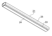
次に、図8はこの発明の実施の形態3による移動型X線装置の操作ハンドルを示す正面図、図9は図8の操作ハンドルを示す底面図、図10は図8の操作ハンドルを斜め上から見た斜視図、図11は図8の操作ハンドルを斜め下から見た斜視図、図12は図8のXII−XII線に沿う断面図である。実施の形態1、2では、ハンドル本体11の断面の上下方向寸法を変更可能としたが、実施の形態3では、ハンドル本体11の断面の前後方向寸法を変更可能としている。
Embodiment 3 FIG.
8 is a front view showing the operation handle of the mobile X-ray apparatus according to Embodiment 3 of the present invention, FIG. 9 is a bottom view showing the operation handle of FIG. 8, and FIG. 10 is an oblique view of the operation handle of FIG. 11 is a perspective view as seen from above, FIG. 11 is a perspective view of the operation handle shown in FIG. 8 as viewed obliquely from below, and FIG. 12 is a cross-sectional view taken along line XII-XII in FIG. In the first and second embodiments, the vertical dimension of the cross section of the
実施の形態3の操作ハンドルは、筒状のハンドル本体21、ハンドル本体21内に設けられている複数(この例では2個)のブレーキ解除スイッチ22(図12)、及びブレーキ解除スイッチ22を操作するためのスイッチバー23を有している。
The operation handle according to the third embodiment operates a cylindrical handle
ハンドル本体21は、断面U字形の第1のハンドル部材24、及び第1のハンドル部材24に嵌め合わされている断面U字形の第2のハンドル部材25を有している。第1のハンドル部材24と第2のハンドル部材25とは、台車1の前後方向(図12の左右方向)に互いに逆向きに並べて組み合わされている。
The handle
図12に示すように、第1のハンドル部材24は、互いに対向する一対の第1の水平部24a,24b、及び第1の水平部24a,24bの端部間に位置する第1の側面部24cを有している。
As shown in FIG. 12, the
第2のハンドル部材25は、互いに対向する一対の第2の水平部25a,25b、及び第2の水平部25a,25bの端部間に位置する第2の側面部25cを有している。
The
第2の水平部25a,25bは、第1の水平部24a,24b間に挿入されている。また、第2の水平部25aの上面は第1の水平部24aの下面に接しており、第2の水平部25bの下面は第1の水平部24bの上面に接している。
The second
第2のハンドル部材25は、複数の締結具26により第1のハンドル部材24に固定されている。締結具26としては、例えば六角穴付きボルト又は皿ねじ等が用いられる。第2の水平部25a,25bには、締結具26に対応する複数のねじ穴25dが設けられている。ねじ穴25dの数は、締結具26の数よりも多い。
The
この例では、1本の締結具26に対して、3つのねじ穴25dが台車1の前後方向に互いに間隔をおいて配置されている。締結具26を締め込むねじ穴25dを選択することにより、第2のハンドル部材25の第1のハンドル部材24への挿入深さ(嵌め合わせ深さ)が段階的に変更可能になっている。これにより、ハンドル本体21の長さ方向に直角な断面(図12)の大きさ(太さ)が段階的に変更可能となっている。即ち、実施の形態3のサイズ調整機構27は、締結具26及びねじ穴25dにより構成されている。
In this example, three
ブレーキ解除スイッチ22は、実施の形態1のブレーキ解除スイッチ12と同様のスイッチであり、第2の側面部25cに固定されたスイッチ基板28の下面に取り付けられている。
The
第2の水平部25bには、スイッチバー23を通すスイッチバー孔25eが設けられている。他の構成は、実施の形態1と同様である。
The second
このような構成によっても、実施の形態1と同様に、ハンドル本体21の断面の大きさを予め調整しておくことで、走行時の操作者の負担を軽減し、操作性を向上させることができる。
Even with such a configuration, as in the first embodiment, by adjusting the size of the cross section of the handle
なお、実施の形態3のハンドル本体21に実施の形態2のブレーキ解除スイッチ19を適用してもよい。
また、実施の形態3では、第1のハンドル部材24を前側に配置し、第2のハンドル部材25を後ろ側に配置したが、前後逆に配置してもよい。
The
In the third embodiment, the
実施の形態4.
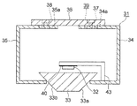
次に、図13はこの発明の実施の形態4による移動型X線装置の操作ハンドルの断面図である。実施の形態4の操作ハンドルは、筒状のハンドル本体31、ハンドル本体31内に設けられている複数(この例では2個)のブレーキ解除スイッチ32、及びブレーキ解除スイッチ32を操作するためのスイッチバー33を有している。
Embodiment 4 FIG.
Next, FIG. 13 is a sectional view of an operation handle of a mobile X-ray apparatus according to Embodiment 4 of the present invention. The operation handle of the fourth embodiment includes a cylindrical handle
ハンドル本体31は、断面コ字形の第1のハンドル部材34、第1のハンドル部材34に対向する断面コ字形の第2のハンドル部材35、及び第1のハンドル部材34の上面部と第2のハンドル部材35の上面部とに連結されている連結部材としての連結板36を有している。第1のハンドル部材34と第2のハンドル部材35とは、台車1の前後方向(図13の左右方向)に互いに逆向きに並べて配置されている。
The
連結板36は、ハンドル本体31の長さ方向に互いに間隔をおいて配置された複数の第1の締結具37により第1のハンドル部材34に固定されている。また、連結板36は、ハンドル本体31の長さ方向に互いに間隔をおいて配置された複数の第2の締結具38により第2のハンドル部材35に固定されている。締結具37,38としては、例えば六角穴付きボルト又は皿ねじ等が用いられる。
The connecting
第1のハンドル部材34の上面部には、第1の締結具37に対応する複数の第1のねじ穴34aが設けられている。第1のねじ穴34aの数は、第1の締結具37の数よりも多い。
A plurality of first screw holes 34 a corresponding to the
第2のハンドル部材35の上面部には、第2の締結具38に対応する複数の第2のねじ穴35aが設けられている。第2のねじ穴35aの数は、第2の締結具38の数よりも多い。
A plurality of second screw holes 35 a corresponding to the
締結具37,38を締め込むねじ穴34a,35aを選択することにより、第1のハンドル部材34と第2のハンドル部材35との間の間隔が調整可能になっている。これにより、ハンドル本体31の長さ方向に直角な断面(図13)の大きさ(太さ)が段階的に変更可能となっている。即ち、実施の形態3のサイズ調整機構39は、締結具37,38及びねじ穴34a,35aにより構成されている。
The distance between the
ブレーキ解除スイッチ32は、実施の形態1のブレーキ解除スイッチ12と同様のスイッチであり、スイッチ基板40の下面に取り付けられている。スイッチ基板40は、第1のハンドル部材34に固定された第1の支持部材41と、第2のハンドル部材35に固定された第2の支持部材42とにより、摺動可能に支持されている。
The
スイッチバー33は、その上面がブレーキ解除スイッチ32に対向するように、第1のハンドル部材34の下面部と第2のハンドル部材35の下面部との間に配置されている。スイッチバー33の断面形状は、台形である。即ち、スイッチバー33は、第1及び第2のハンドル部材34,35に接するテーパ状の傾斜面33a,33bを有している。他の構成は、実施の形態1と同様である。
The
このような構成によっても、実施の形態1と同様に、ハンドル本体31の断面の大きさを予め調整しておくことで、走行時の操作者の負担を軽減し、操作性を向上させることができる。
Even with such a configuration, as in the first embodiment, by adjusting the size of the cross section of the handle
実施の形態5.
次に、図14はこの発明の実施の形態5による移動型X線装置の操作ハンドルの断面図である。実施の形態5では、スイッチ基板40が、第1のハンドル部材34に固定された支持部材43により片持ち支持されている。他の構成は、実施の形態4と同様である。
Next, FIG. 14 is a sectional view of the operation handle of the mobile X-ray apparatus according to
このような構成によっても、走行時の操作者の負担を軽減し、操作性を向上させることができる。また、ブレーキ解除スイッチ32の支持構造を簡素化することができる。
Even with such a configuration, the burden on the operator during traveling can be reduced, and the operability can be improved. Moreover, the support structure of the
実施の形態6.
次に、図15はこの発明の実施の形態6による移動型X線装置の操作ハンドルの断面図である。図において、ハンドル本体11内には、第2のハンドル部材15の第1のハンドル部材14への挿入深さ(嵌め合わせ深さ)を連続的に変更するサイズ変更アクチュエータとしてのサイズ変更モータ51が設けられている。この例では、サイズ変更モータ51は、スイッチ基板18上に設けられている。
Embodiment 6 FIG.
Next, FIG. 15 is a sectional view of an operation handle of a mobile X-ray apparatus according to Embodiment 6 of the present invention. In the figure, a
サイズ変更モータ51の回転軸には、ねじ棒52が設けられている。上面部14cの下面には、ねじ棒受け部材53が固定されている。ねじ棒受け部材53には、ねじ穴が設けられている。サイズ変更モータ51は、操作者が操作ボタン(図示せず)を操作することにより、正逆方向へ選択的に回転力を発生する。
A
サイズ変更モータ51によりねじ棒52を回転させることにより、ねじ棒受け部材53へのねじ棒52のねじ込み量が変化し、第2のハンドル部材15の第1のハンドル部材14への挿入深さが連続的に変更可能になっている。これにより、ハンドル本体11の長さ方向に直角な断面(図15)の大きさ(太さ)が連続的に変更可能となっている。即ち、実施の形態6のサイズ調整機構54は、サイズ変更モータ51、ねじ棒52及びねじ棒受け部材53を有している。他の構成は、実施の形態1と同様である。
When the
このような移動型X線装置では、ハンドル本体11にサイズ調整機構54が設けられているため、ハンドル本体11の断面の大きさを予め調整しておくことで、走行時の操作者の負担を軽減し、操作性を向上させることができる。
In such a mobile X-ray apparatus, since the handle
また、サイズ変更モータ51の駆動力を用いてハンドル本体11の断面の大きさを変更するので、操作が容易である。さらに、ハンドル本体11の断面の大きさを連続的に変更することができるので、走行時の操作者の負担をさらに軽減することができる。
Further, since the size of the cross section of the
なお、実施の形態2〜5に示したタイプの操作ハンドルに、実施の形態6のようなタイプのサイズ調整機構54を適用してもよい。
また、サイズ変更アクチュエータは、サイズ変更モータに限定されるものではなく、例えば、リニアモータ、油圧シリンダ又はエアシリンダ等であってもよい。
さらに、ハンドル本体の断面の大きさを段階的に変更可能とする場合(実施の形態1〜5)、段階数は特に限定されるものではない。
Note that the
Further, the size changing actuator is not limited to the size changing motor, and may be, for example, a linear motor, a hydraulic cylinder, an air cylinder or the like.
Further, when the size of the cross section of the handle body can be changed in stages (Embodiments 1 to 5), the number of stages is not particularly limited.
1 台車、2前輪(車輪)、3 後輪(車輪)、4 X線装置本体、8 走行用モータ、10 操作ハンドル、11,21,31 ハンドル本体、12,19,22,32 ブレーキ解除スイッチ、14,24,34 第1のハンドル部材、15,25,35 第2のハンドル部材、15d,25d ねじ穴、16,26 締結具、17,27,39,54 サイズ調整機構、51 サイズ変更モータ(サイズ変更アクチュエータ)。 1 bogie, 2 front wheels (wheels), 3 rear wheels (wheels), 4 X-ray device body, 8 travel motor, 10 operation handle, 11, 21, 31 handle body, 12, 19, 22, 32 brake release switch, 14, 24, 34 First handle member, 15, 25, 35 Second handle member, 15d, 25d Screw hole, 16, 26 Fastener, 17, 27, 39, 54 Size adjustment mechanism, 51 Size change motor ( Resize actuator).
Claims (6)
前記台車に搭載されているX線装置本体、
前記台車に搭載されており、前記車輪を駆動する走行用モータ、及び
ハンドル本体と、前記台車の走行を阻止するブレーキを解除するためのブレーキ解除スイッチとを有しており、かつ前記台車に設けられている操作ハンドル
を備え、
前記操作ハンドルには、前記ハンドル本体の長さ方向に直角な断面の大きさを変更するためのサイズ調整機構が設けられていることを特徴とする移動型X線装置。 A carriage having a plurality of wheels,
An X-ray apparatus main body mounted on the carriage,
The trolley is mounted on the carriage, has a traveling motor that drives the wheels, a handle body, and a brake release switch for releasing a brake that prevents the carriage from traveling. With an operating handle
The movable X-ray apparatus, wherein the operation handle is provided with a size adjusting mechanism for changing a size of a cross section perpendicular to the length direction of the handle body.
前記サイズ調整機構により、前記第2のハンドル部材の前記第1のハンドル部材への挿入深さが調整可能になっていることを特徴とする請求項1記載の移動型X線装置。 The handle body has a first handle member and a second handle member fitted to the first handle member,
The mobile X-ray apparatus according to claim 1, wherein an insertion depth of the second handle member into the first handle member can be adjusted by the size adjusting mechanism.
前記サイズ調整機構により、前記第1のハンドル部材と前記第2のハンドル部材との間の間隔が調整可能になっていることを特徴とする請求項1記載の移動型X線装置。 The handle body is connected between the first handle member, the second handle member facing the first handle member, and the first handle member and the second handle member. And has a member,
The mobile X-ray apparatus according to claim 1, wherein a distance between the first handle member and the second handle member is adjustable by the size adjusting mechanism.
前記締結具を締め込む前記ねじ穴を選択することにより、前記第2のハンドル部材の前記第1のハンドル部材への挿入深さが調整可能になっていることを特徴とする請求項2記載の移動型X線装置。 The size adjusting mechanism includes a fastener for fixing the second handle member to the first handle member, and a plurality of screw holes provided in the second handle member.
The insertion depth of the second handle member into the first handle member can be adjusted by selecting the screw hole into which the fastener is tightened. Mobile X-ray device.
前記第1の締結具を締め込む前記第1のねじ穴を選択するとともに、前記第2の締結具を締め込む前記第2のねじ穴を選択することにより、前記第1のハンドル部材と前記第2のハンドル部材との間の間隔が調整可能になっていることを特徴とする請求項3記載の移動型X線装置。 The size adjusting mechanism includes a first fastener for fixing the connection member to the first handle member, a plurality of first screw holes provided in the first handle member, and the connection A second fastener for fixing a member to the second handle member; and a plurality of second screw holes provided in the second handle member;
By selecting the first screw hole for tightening the first fastener and selecting the second screw hole for tightening the second fastener, the first handle member and the first screw hole are selected. 4. The mobile X-ray apparatus according to claim 3, wherein a distance between the two handle members is adjustable.
Priority Applications (1)
| Application Number | Priority Date | Filing Date | Title |
|---|---|---|---|
| JP2014000339A JP2015128473A (en) | 2014-01-06 | 2014-01-06 | Mobile x-ray device |
Applications Claiming Priority (1)
| Application Number | Priority Date | Filing Date | Title |
|---|---|---|---|
| JP2014000339A JP2015128473A (en) | 2014-01-06 | 2014-01-06 | Mobile x-ray device |
Publications (2)
| Publication Number | Publication Date |
|---|---|
| JP2015128473A true JP2015128473A (en) | 2015-07-16 |
| JP2015128473A5 JP2015128473A5 (en) | 2017-02-09 |
Family
ID=53759758
Family Applications (1)
| Application Number | Title | Priority Date | Filing Date |
|---|---|---|---|
| JP2014000339A Pending JP2015128473A (en) | 2014-01-06 | 2014-01-06 | Mobile x-ray device |
Country Status (1)
| Country | Link |
|---|---|
| JP (1) | JP2015128473A (en) |
Cited By (1)
| Publication number | Priority date | Publication date | Assignee | Title |
|---|---|---|---|---|
| CN110464381A (en) * | 2019-09-03 | 2019-11-19 | 赵新华 | A kind of mobile device of ophthalmic ultrasonic diagnostic equipment |
Citations (5)
| Publication number | Priority date | Publication date | Assignee | Title |
|---|---|---|---|---|
| JPS50129076U (en) * | 1974-03-29 | 1975-10-23 | ||
| JPS5814898U (en) * | 1981-07-23 | 1983-01-29 | 東芝熱器具株式会社 | Equipment with grip |
| JPS63315389A (en) * | 1987-06-19 | 1988-12-23 | 本田技研工業株式会社 | Variable diameter type handle-grip for minicar |
| JPH066067U (en) * | 1992-06-29 | 1994-01-25 | 株式会社島津製作所 | Mobile X-ray equipment |
| JP2004121656A (en) * | 2002-10-04 | 2004-04-22 | Shimadzu Corp | Radiographing apparatus for rounds |
-
2014
- 2014-01-06 JP JP2014000339A patent/JP2015128473A/en active Pending
Patent Citations (5)
| Publication number | Priority date | Publication date | Assignee | Title |
|---|---|---|---|---|
| JPS50129076U (en) * | 1974-03-29 | 1975-10-23 | ||
| JPS5814898U (en) * | 1981-07-23 | 1983-01-29 | 東芝熱器具株式会社 | Equipment with grip |
| JPS63315389A (en) * | 1987-06-19 | 1988-12-23 | 本田技研工業株式会社 | Variable diameter type handle-grip for minicar |
| JPH066067U (en) * | 1992-06-29 | 1994-01-25 | 株式会社島津製作所 | Mobile X-ray equipment |
| JP2004121656A (en) * | 2002-10-04 | 2004-04-22 | Shimadzu Corp | Radiographing apparatus for rounds |
Cited By (1)
| Publication number | Priority date | Publication date | Assignee | Title |
|---|---|---|---|---|
| CN110464381A (en) * | 2019-09-03 | 2019-11-19 | 赵新华 | A kind of mobile device of ophthalmic ultrasonic diagnostic equipment |
Similar Documents
| Publication | Publication Date | Title |
|---|---|---|
| US20180244294A1 (en) | Carriage | |
| US9580139B2 (en) | Electric kick scooter | |
| US8776941B2 (en) | Road finishing machine with adjustable control panel | |
| JP2008511483A5 (en) | ||
| JP6672106B2 (en) | Cart | |
| KR101576791B1 (en) | Longitudinally adjustable vehicle seat | |
| US10308114B2 (en) | Hand control throttle system | |
| JP2006298157A (en) | Auxiliary powered vehicle for cart | |
| JP2016202609A (en) | Walking aid vehicle | |
| JP3204508U (en) | Hand rest | |
| JP2015128473A (en) | Mobile x-ray device | |
| JP5425587B2 (en) | Wheelchair electrification device | |
| KR101440447B1 (en) | wheelchair with brake using eddy current | |
| JP6544689B2 (en) | Operation grip and moving body | |
| JP2009178122A5 (en) | ||
| US7815009B1 (en) | Golf cart actuating system | |
| KR20190100015A (en) | Wheel chair having an auxiliary force generating device | |
| KR101539195B1 (en) | The cart for car washing | |
| JP5809085B2 (en) | Rice transplanter | |
| JP6527652B2 (en) | Dolly | |
| KR101504323B1 (en) | Auxiliary device for driving of the disabled | |
| US20120138381A1 (en) | Steering device for an electric vehicle | |
| JP6801212B2 (en) | Small electric vehicle | |
| JP2015128473A5 (en) | ||
| JP2006168484A (en) | Accelerator lever of electric wheelchair |
Legal Events
| Date | Code | Title | Description |
|---|---|---|---|
| RD04 | Notification of resignation of power of attorney |
Free format text: JAPANESE INTERMEDIATE CODE: A7424 Effective date: 20160330 |
|
| A711 | Notification of change in applicant |
Free format text: JAPANESE INTERMEDIATE CODE: A712 Effective date: 20160427 |
|
| A521 | Request for written amendment filed |
Free format text: JAPANESE INTERMEDIATE CODE: A523 Effective date: 20161226 |
|
| A621 | Written request for application examination |
Free format text: JAPANESE INTERMEDIATE CODE: A621 Effective date: 20161226 |
|
| A977 | Report on retrieval |
Free format text: JAPANESE INTERMEDIATE CODE: A971007 Effective date: 20170920 |
|
| A131 | Notification of reasons for refusal |
Free format text: JAPANESE INTERMEDIATE CODE: A131 Effective date: 20170926 |
|
| A02 | Decision of refusal |
Free format text: JAPANESE INTERMEDIATE CODE: A02 Effective date: 20180327 |